EP1632356B1 - Tintenstrahldrucker, Steuerungverfahren und Computerprogrammprodukt dafür - Google Patents
Tintenstrahldrucker, Steuerungverfahren und Computerprogrammprodukt dafür Download PDFInfo
- Publication number
- EP1632356B1 EP1632356B1 EP05254026A EP05254026A EP1632356B1 EP 1632356 B1 EP1632356 B1 EP 1632356B1 EP 05254026 A EP05254026 A EP 05254026A EP 05254026 A EP05254026 A EP 05254026A EP 1632356 B1 EP1632356 B1 EP 1632356B1
- Authority
- EP
- European Patent Office
- Prior art keywords
- ink jet
- print data
- ink
- jet printer
- printing
- Prior art date
- Legal status (The legal status is an assumption and is not a legal conclusion. Google has not performed a legal analysis and makes no representation as to the accuracy of the status listed.)
- Ceased
Links
- 238000000034 method Methods 0.000 title claims description 53
- 238000004590 computer program Methods 0.000 title claims description 9
- 238000007639 printing Methods 0.000 claims description 330
- 230000009471 action Effects 0.000 claims description 170
- 238000011010 flushing procedure Methods 0.000 claims description 88
- 238000007599 discharging Methods 0.000 claims description 61
- 238000011144 upstream manufacturing Methods 0.000 claims description 11
- 239000000976 ink Substances 0.000 description 347
- 230000008569 process Effects 0.000 description 36
- 238000012545 processing Methods 0.000 description 17
- 238000004891 communication Methods 0.000 description 15
- 238000001514 detection method Methods 0.000 description 15
- 230000008859 change Effects 0.000 description 5
- 238000012217 deletion Methods 0.000 description 4
- 230000037430 deletion Effects 0.000 description 4
- 239000000853 adhesive Substances 0.000 description 3
- 230000001070 adhesive effect Effects 0.000 description 3
- 239000000203 mixture Substances 0.000 description 3
- 230000002093 peripheral effect Effects 0.000 description 3
- 238000007789 sealing Methods 0.000 description 3
- 230000032258 transport Effects 0.000 description 3
- 238000004140 cleaning Methods 0.000 description 2
- 230000006870 function Effects 0.000 description 2
- 238000003825 pressing Methods 0.000 description 2
- 238000011084 recovery Methods 0.000 description 2
- 238000000844 transformation Methods 0.000 description 2
- 230000009466 transformation Effects 0.000 description 2
- XUIMIQQOPSSXEZ-UHFFFAOYSA-N Silicon Chemical compound [Si] XUIMIQQOPSSXEZ-UHFFFAOYSA-N 0.000 description 1
- 239000011358 absorbing material Substances 0.000 description 1
- 238000004364 calculation method Methods 0.000 description 1
- 239000003086 colorant Substances 0.000 description 1
- 230000006866 deterioration Effects 0.000 description 1
- 239000004744 fabric Substances 0.000 description 1
- -1 for example Substances 0.000 description 1
- 238000005304 joining Methods 0.000 description 1
- 238000004519 manufacturing process Methods 0.000 description 1
- 239000000463 material Substances 0.000 description 1
- 239000011159 matrix material Substances 0.000 description 1
- 238000005259 measurement Methods 0.000 description 1
- 230000007246 mechanism Effects 0.000 description 1
- 239000007769 metal material Substances 0.000 description 1
- 238000012986 modification Methods 0.000 description 1
- 230000004048 modification Effects 0.000 description 1
- 229910052710 silicon Inorganic materials 0.000 description 1
- 239000010703 silicon Substances 0.000 description 1
- 229910001220 stainless steel Inorganic materials 0.000 description 1
- 239000010935 stainless steel Substances 0.000 description 1
Images




Classifications
-
- B—PERFORMING OPERATIONS; TRANSPORTING
- B41—PRINTING; LINING MACHINES; TYPEWRITERS; STAMPS
- B41J—TYPEWRITERS; SELECTIVE PRINTING MECHANISMS, i.e. MECHANISMS PRINTING OTHERWISE THAN FROM A FORME; CORRECTION OF TYPOGRAPHICAL ERRORS
- B41J13/00—Devices or arrangements of selective printing mechanisms, e.g. ink-jet printers or thermal printers, specially adapted for supporting or handling copy material in short lengths, e.g. sheets
- B41J13/0009—Devices or arrangements of selective printing mechanisms, e.g. ink-jet printers or thermal printers, specially adapted for supporting or handling copy material in short lengths, e.g. sheets control of the transport of the copy material
- B41J13/0027—Devices or arrangements of selective printing mechanisms, e.g. ink-jet printers or thermal printers, specially adapted for supporting or handling copy material in short lengths, e.g. sheets control of the transport of the copy material in the printing section of automatic paper handling systems
-
- B—PERFORMING OPERATIONS; TRANSPORTING
- B41—PRINTING; LINING MACHINES; TYPEWRITERS; STAMPS
- B41J—TYPEWRITERS; SELECTIVE PRINTING MECHANISMS, i.e. MECHANISMS PRINTING OTHERWISE THAN FROM A FORME; CORRECTION OF TYPOGRAPHICAL ERRORS
- B41J13/00—Devices or arrangements of selective printing mechanisms, e.g. ink-jet printers or thermal printers, specially adapted for supporting or handling copy material in short lengths, e.g. sheets
- B41J13/0009—Devices or arrangements of selective printing mechanisms, e.g. ink-jet printers or thermal printers, specially adapted for supporting or handling copy material in short lengths, e.g. sheets control of the transport of the copy material
Definitions
- the present invention relates to an ink jet printer, a method for controlling an ink jet printer, and a computer program product for an ink jet printer.
- Ink jet printers are well known.
- An ink jet printer receives print data files that are output from an external device such as personal computer, a digital camera, etc.
- the ink jet printer is provided with an ink jet head and a controller.
- the ink jet head executes a printing action whereby ink is discharged onto a print medium.
- the controller controls the ink jet head such that the content of the received print data will be printed.
- a large amount of print data is contained in one print data file, it takes time for all of the print data to be received.
- printing takes a long time if the printing action is started when the ink jet printer has received all the print data included in the print data file.
- the following ink jet printer has been developed.
- this predetermined amount of print data is printed. For example, in the case where one print data file contains print data equivalent to fifty lines of a printing paper, ten lines of the print data is printed as soon as the ten lines of print data have been received. In this ink jet printer, when print data corresponding to the first ten lines has been received, the printing action of these ten lines begins. Further print data is received while this printing action is taking place. When print data corresponding to the lines 11 to 20 has been received, the printing action of these lines 11 to 20 begins. The remaining print data is printed in the same manner.
- ink jet printer printing is begun before the entirety of the print data contained in the print data file has been received. Since printing is taking place at the same time as the print data is being received, the time required for printing can be reduced.
- This type of ink jet printer is taught in Japanese Patent Application Publication No. 05-96826 .
- Communication between the ink jet printer and the external device does not always proceed smoothly. In that case, there is a long time between beginning reception of a predetermined amount of print data and completing the reception of the print data. When it takes a long time to complete reception of the predetermined amount of print data, there is a long time between completing the last printing action and restarting printing action of the predetermined amount of print data. In that case, the situation may occur in which a long period elapses between the last printing action of a print medium that has been partially printed, and the further printing action thereof. The present inventor has discovered that, in this situation, there is a change in printing quality between the portion that was partially printed earlier, and the portion that was printed subsequently.
- 'a change in printing quality' includes both a situation where the printing quality changes only at a boundary between earlier and subsequent printing, and a situation where the printing quality has changed in the entire portion after this boundary. It is unsightly for a single print medium to have a portion in which the printing quality is different.
- JP-A-01206058 considers preventing the data normally printed already on a paper in a paper jamming from overlap-printing after the recovery of the paper jamming, by a method wherein with the detection of a paper discharge by a paper sensor, the printed data for one page is erased from a receiving buffer.
- a paper sensor for detecting the discharge of a printed-out paper from a paper discharge port is disposed in the vicinity of the paper discharge port formed at the end of a paper feed path. After the discharge of the paper is identified by the paper sensor, character data for one page in a receive buffer is erased.
- a processing to cope with a paper jamming is conducted.
- a paper jamming recovery operation such as a restart, thereby restarting a printing action from character data for one page which has been last-printed out in the receive buffer.
- a paper jamming recovery operation such as a restart
- an inkjet printer as defined in appended claim 1.
- this ink jet printer when there is no printing for a long period of a partially printed print medium, this print medium is not printed further, and the print medium is ejected instead. Unsightly printing can thus be prevented.
- the controller performs the following operations. It is preferred that the controller controls the ink jet head to execute a flushing action in the case where the time since the last printing action has exceeded a predetermined time.
- the flushing action is an action wherein the ink jet head discharges ink so as to recover an ink discharging ability of the ink jet head.
- flushing action is executed not based on the print data.
- the viscous ink is discharged by means of the flushing action. It is thus possible to prevent the viscous ink from being discharged onto a new print medium that is being printed. High printing quality printing can thus be achieved.
- the ink jet printer may have a position sensor that detects a position of the partially printed print medium. (1) If the position of the print medium is a facing position at which all ink discharge nozzles of the ink jet head are facing the print medium or (2) if the position of the print medium is upstream from the facing position and only some of the ink discharge nozzles are facing the print medium, the controller may control the ink jet head to execute the flushing action by discharging ink toward the partially printed print medium, and the controller controls the transportation device to eject the print medium after the flushing action.
- the controller may control the ink jet head to execute the flushing action by discharging ink toward the transportation device after the partially printed print medium has been ejected.
- flushing is performed by discharging ink toward the partially printed print medium.
- flushing is performed by discharging ink toward the transportation device. According to these forms, there is no need for a special device for receiving the flushed ink. Flushing can be executed using the structure required by the normal ink jet printer. Since flushing can, according to circumstances, be performed by discharging the ink toward the print medium, it is possible to reduce the number of times in which ink is discharged toward the transportation device. The transportation device therefore requires less frequent cleaning.
- the ink jet printer may have a memory that stores the print data that was output from the external device.
- the controller may delete all the print data included in the print data file from the memory when all the print data included in the print data file has been printed.
- the controller may control the ink jet head to execute the printing action, based on the print data that has been stored in the memory, onto a new print medium. After the partially printed print medium has been ejected, printing of a new print medium can be performed once again. Since the print data is stored in the print data file, it is not necessary to receive the print data once more. Printing can therefore be completed within a short period.
- the ink jet head in a line printer is comparatively large and, as a result, it is not easy to move the ink jet head.
- the technique of the present invention is therefore suitable for a line printer.
- An ink jet printer may also be provided that has an ink jet head and a controller.
- the ink jet head may execute the printing action in which it discharges ink toward the print medium.
- the ink jet head may execute a flushing action in which it discharges ink to recover an ink discharging ability of the ink jet head.
- the controller may control the ink jet head to execute the printing action when the ink jet printer has finished receiving a predetermined amount of print data, and may control the ink jet head to execute the flushing action to discharge ink toward a partially printed print medium in a case where time since a last printing action has exceeded a predetermined time.
- a method for controlling the ink jet printer can also be taught as defined in appended claim 14. With this method, when printing of the partially printed print medium has not been executed for a long time, this print medium is not printed further, and instead the print medium is ejected. As a result, unsightly printing can be prevented.
- the method may further include a step of controlling the ink jet printer such that, in the case where the time since the last printing action has exceeded the predetermined time, the ink jet printer executes a flushing action in which ink is discharged so as to recover an ink discharging ability.
- the viscous ink is discharged by the flushing action. It is thus possible to prevent the viscous ink from being discharged onto a new print medium that is being printed. High printing quality printing can thus be achieved.
- the present technique can be expressed as a computer program product as defined in appended claim 18.
- this program product prevents further printing of this print medium, and causes the print medium to be ejected. As a result, unsightly printing can be prevented.
- the computer program product may further include instructions such that, in the case where the time since the last printing action has exceeded the predetermined time, the computer device is caused to perform a step of controlling the ink jet printer to execute a flushing action in which ink is discharged so as to recover an ink discharging ability.
- the viscous ink is discharged by the flushing action. It is thus possible to prevent the viscous ink from being discharged onto a new print medium that is being printed. High printing quality printing can thus be achieved.
- An ink jet printer taught in the present specification prevents further printing of a partially printed print medium in the case where a long time has elapsed since a last printing action. A situation is thus prevented in which different portions of a single print medium have different printing quality. It can be hypothesized that this change in printing quality occurs for the following reason. The following reason is a hypothesis, however, and does not limit the technical scope of the present invention. The technical scope of the present invention is construed according to the elements set forth in the claims.
- an ink jet head is provided with a plurality of nozzles. Each nozzle discharges ink droplets towards a print medium. A plurality of the ink droplets impacts against the print medium, thus printing a desired image or letters thereon.
- the point at which the ink droplets impact against the print medium is termed an impact point.
- an impact point In the case where, for example, a color image is to be printed, different colored inks are caused to impact against the same impact point, thus causing a mixture of colors.
- the state of dryness of a first color ink and the extent to which the print medium is penetrated differ between a case where a second color ink has been caused to impact against the impact point of the first color ink after a short interval has elapsed, and in a case where the second color ink has been caused to impact against the impact point of the first color ink after a long interval has elapsed. There is a difference in the color mixtures of the former case and the latter case.
- FIG. 1 is a side view of a portion of an ink jet printer of a representative embodiment of the present teachings.
- An ink jet printer 101 is a color ink jet printer.
- the ink jet printer 101 has four ink jet heads 1a, 1b, 1c, and 1d.
- the ink jet head 1a has an ink discharging face 2a at its lower face.
- the ink discharging face 2a discharges ink downwards.
- the ink jet heads 1b to 1d have ink discharging faces 2b to 2d for discharging ink.
- the ink discharging face 2a has a plurality of nozzles that can print ten lines of a printing paper simultaneously.
- each ink discharging face 2b to 2d has a plurality of nozzles that can print ten lines of a printing paper simultaneously.
- the ink jet heads 1a to 1d will be described in detail later. Further, the number 1 is used below to represent the ink jet heads 1a to 1d. Moreover, the number 2 is used to represent the ink discharging faces 2a to 2d.
- the ink jet printer 101 has a paper supply part 111 and a paper ejection part 112. The paper supply part 111 is located at the left side and the paper ejection part 112 is located at the right side. Furthermore, the ink jet printer 101 is provided with a controller 60 (see FIG. 5 ) that controls operations of the ink jet printer 101.
- a transportation path 200 is formed within the ink jet printer 101.
- the transportation path 200 transports printing paper from the paper supply part 111 to the paper ejection part 112.
- a pair of rollers 105a and 105b is disposed at the immediate downstream side of the paper supply part 111.
- the rollers 105a and 105b grip paper in the paper supply part 111, and deliver this paper towards the right.
- the rollers 105a and 105b are connected with a motor (not shown).
- the motor is controlled by the controller 60.
- a printing paper transportation device 103 is provided at a central part of the transportation path 200.
- the printing paper transportation device 103 is provided with a pair of belt rollers 106 and 107, a transportation belt 108, and a motor 142 (see FIG. 5 ).
- the pair of belt rollers 106 and 107 extends parallel with a vertical direction relative to the page of FIG. 1 .
- the belt roller 107 is located at a left side with respect to the ink jet head 2a (i.e. at the upstream side of the transportation path 200).
- the belt roller 106 is located at a right side with respect to the ink jet head 2d (i.e. at the downstream side of the transportation path 200).
- the transportation belt 108 is wound across the belt rollers 106 and 107. When the belt rollers 106 and 107 rotate towards the right, the transportation belt 108 that is located at an upper side is transported towards the right, and the transportation belt 108 that is located at a lower side is transported towards the left.
- Silicon processing has been performed on an outer peripheral face of the transportation belt 108, thereby providing adhesive force on this outer peripheral face.
- This adhesive force allows the printing paper, which is being transported by the rollers 105a and 105b, to be maintained on the transportation belt 108.
- the transportation belt 108 has a double-layered structure in which two sheet shaped members have been bonded together.
- An inner sheet shaped member of these two sheet shaped members is formed from liquid-absorbing woven or nonwoven cloth, or the like.
- An outer sheet shaped member of the two is formed from a rubber material.
- a portion 102 of the inner sheet shaped member is not covered by the outer sheet shaped member. That is, a recess 102 is formed in the outer peripheral face of the transportation belt 108.
- This recess 102 has a depth identical with the thickness of the outer sheet shaped member.
- the recess 102 receives ink that is discharged from the ink jet heads 1 when a flushing action is executed. The flushing action will be described in detail later.
- the recess 102 is larger than a single ink discharging face 2, thus ensuring that the ink discharged from the ink discharging face 2 will be received reliably by the recess 102. It is thus possible to prevent ink from being deposited on other locations. Further, the ink jet printer 101 is adjusted such that the printing paper that is being transported does not make contact with the recess 102.
- the motor 142 is connected with the belt roller 106. This motor 142 causes the belt roller 106 to rotate. When the belt roller 106 rotates, the belt roller 107 follows this rotation.
- the ink jet printer 101 is provided with positioning sensors 109 and 110.
- the positioning sensor 109 is provided upstream from the ink jet head 1a.
- the positioning sensor 110 is provided downstream from the ink jet head 1d.
- the positioning sensors 109 and 110 output detection signals to the controller 60 (see FIG. 5 ).
- the positioning sensor 109 outputs the detection signals while the printing paper is facing (is directly below) the positioning sensor 109, and does not output the detection signals when the printing paper is not present in that location.
- the positioning sensor 110 outputs the detection signals while the printing paper is facing (is directly below) the positioning sensor 110, and does not output the detection signals when the printing paper is not present in that location.
- the controller 60 can determine the location of the printing paper by fetching the detection signals from the positioning sensors 109 and 110.
- the controller 60 can determine the location of the printing paper in the following manner. (1) In the case where the positioning sensor 109 is outputting the detection signals and the positioning sensor 110 is not outputting the detection signals, the controller 60 can determine that an anterior end of the printing paper is passing the positioning sensor 109 and the anterior end thereof is not yet passing the positioning sensor 110. Below, this position will be termed a first position. In this first position, only some nozzles are facing the printing paper. (2) In the case where both the positioning sensors 109 and 110 are outputting the detection signals, the controller 60 can determine that the printing paper is located below both the positioning sensors 109 and 110. That is, it can determine that the printing paper is in a position facing all the ink discharging faces 2a to 2d. Below, this position will be termed a second position.
- the controller 60 can determine that the posterior end of the printing paper is between the positioning sensors 109 and 110. Below, this position will be termed a third position. In this third position, only some nozzles are facing the printing paper.
- FIG. 2 is a perspective view of the ink jet head 1a.
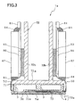
- FIG. 3 is a cross-sectional view along the line III-III of FIG. 2 .
- the ink jet head 1a is provided with a head main body 70a, a base block 71, etc.
- head main bodies of the ink jet heads 1b to 1d are shown by the numbers 70b to 70d.
- the head main body 70 has a rectangular shape that extends in a main scanning direction. As shown in FIG. 3 , the head main body 70 includes a flow channel unit 4 and an actuator unit 21. Although this is not shown, a plurality of ink flow channels is formed within the flow channel unit 4. Each ink flow channel is provided with a nozzle and a pressure chamber connected with the nozzle. The nozzles open onto a lower face in FIG. 3 . The pressure chambers are filled with ink. Ink is discharged from the nozzles by changing the capacity of the pressure chambers.
- the flow channel unit 4 is a structure in which a plurality of thin sheets is layered and is bonded together.
- a detailed configuration of the flow channel unit 4 is taught in, for example, US Patent Application Publication No. 2003/0156156A1 .
- the actuator unit 21 is bonded to an upper surface of the flow channel unit 4.
- the ink jet head 1a is provided with a plurality of these actuator units 21 (this is shown in FIG. 4 ).
- Each of the actuator units 21 has a plurality of piezoelectric elements (not shown).
- Each of the piezoelectric elements is located in the vicinity of one of each of the pressure chambers of the flow channel unit 4. Pressure is applied to the pressure chambers when the piezoelectric elements expand, thereby applying pressure to the ink within the pressure chambers. This ink is thus discharged from the nozzles.
- By selecting which of the piezoelectric elements will be deformed it is possible to cause the discharge of ink from desired nozzles.
- a detailed configuration of a piezoelectric actuator is taught in US Patent No. 2003/0156156A1 .
- the base block 71 is disposed above the head main bodies 70. From a plan view, the base block 71 has a rectangular shape that extends in the main scanning direction.
- the base block 71 has two ink stores 3 for storing ink. The ink within these ink stores 3 is supplied to the head main bodies 70.
- the base block 71 is formed from a metal material such as, for example, stainless steel.
- the ink stores 3 extend in a lengthways direction of the base block 71.
- An opening 3b is formed in a lower face 73 of the base block 71.
- the lower face 73 of the base block 71 has a portion 73a in the vicinity of the opening 3b. Only this portion 73a makes contact with the flow channel unit 4.
- the ink jet head 1a has a holder 72, a Flexible Printed Circuit (FPC) 50, a driver IC 80, a heat sink 82, etc.
- the holder 72 is disposed above the base block 71.
- the holder 72 has a holding member 72a and a pair of protrusions 72b.
- the base block 71 is fixed to the holding member 72a of the holder 72.
- the holding member 72a and the base block 71 are bonded by adhesive.
- the protrusions 72b extend upwards from an upper face of the holding member 72a.
- the FPC 50 makes contact with approximately the entirety of an upper face of the actuator unit 21. Current is supplied to each of the piezoelectric elements of the actuator unit 21 via the FPC 50.
- the FPC 50 extends upwards along the protrusions 72b of the holder 72.
- a resilient member 83 such as a sponge is disposed between the FPC 50 and the protrusions 72b of the holder 72.
- the driver IC 80 is disposed at an outer side of the FPC 50.
- the driver IC 80 is soldered to the FPC 50.
- the driver IC 80 supplies a driving signal (i.e. current) to the actuator unit 21 via the FPC 50.
- the heat sink 82 has an approximately rectangular parallelepiped shape.
- the heat sink 82 fits tightly with an outer side of the driver IC 80.
- the heat sink 82 absorbs and dissipates heat generated by the driver IC 80.
- a base plate 81 is disposed above the heat sink 82.
- the base plate 81 is connected with the FPC 50.
- a sealing member 84 is provided between the base plate 81 and an upper face of the heat sink 82.
- a sealing member 84 is also provided between the FPC 50 and a lower face of the heat sink 82.
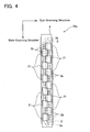
- FIG. 4 is a plan view of the head main body 70a.
- the ink stores 3 within the base block 71 are shown by a broken line.
- the pair of ink stores 3 extends in a parallel manner in an up-down direction.
- the ink store 3 at the left has an opening 3a at a lower side.
- the ink store 3 at the right has an opening 3a at an upper side.
- These openings 3a join with an ink tank (not shown).
- the ink stores 3 have a plurality of openings 3b. These openings 3b are also shown in FIG. 3 .
- the openings 3b join the ink stores 3 with the flow channel unit 4. These openings 3b are disposed so that pairs of openings 3b are adjacent.
- the pairs of mutually adjacent openings 3b of the left side ink store 3, and the pairs of mutually adjacent openings 3b of the right side ink store 3, are disposed in a staggered pattern.
- the adjacent pairs of openings 3b are disposed so as not to overlap, from a plan view, with the actuator units 21.
- the plurality of actuator units 21 is disposed in a staggered pattern.
- the actuator units 21 have a trapezoid shape from a plan view. There is a partial overlap in the left-right direction between the actuator units 21 that are disposed at the left side and the actuator units 21 that are disposed at the right side.
- a plurality of the nozzles (not shown) is disposed in a matrix shape on a lower face (an innermost face with respect to a vertical direction relative to the page of FIG. 4 ) of the flow channel unit 4. These nozzles are formed in regions that, from a plan view, overlap with the actuator units 21. Nozzles are not formed in regions that do not overlap with the actuator units 21.
- a plurality of manifolds (not shown) is formed within the flow channel unit 4. These manifolds join with the openings 3b of the ink stores 3. One of each of the manifolds joins with one of each the pressure chambers in the flow channel unit 4. The ink that has been filled into the ink stores 3 flows into the manifolds via the ink openings 3b.
- the ink is thus transported from the manifolds to each of the pressure chambers, thus filling the pressure chambers with ink.
- the piezoelectric element of the actuator unit 21 is expanded, thereby applying pressure to the pressure chamber, ink is discharged from the nozzle joining with that pressure chamber.
- the configuration of the ink jet head 1a was described in detail.
- the other ink jet heads 1b to 1d have the same configuration as the ink jet head 1a, and therefore a description thereof is omitted.
- the ink jet head 1a discharges cyan ink.
- the ink jet head 1b discharges magenta ink.
- the ink jet head 1c discharges yellow ink.
- the ink jet head 1d discharges black ink. Color images can therefore be printed as desired on the printing paper.
- the ink jet heads 1 extend in a vertical direction with respect to a direction of transportation of the printing paper (a vertical direction with respect to the page of FIG. 1 ).
- the transverse width of the ink jet heads 1 (the width in the vertical direction with respect to the page of FIG. 1 ) is greater than the transverse width of the printing paper.
- the printer 101 is a line type printer.
- the printing paper is transported towards the right, and therefore faces the ink discharging faces 2a to 2d in sequence. Ink is discharged from the ink discharging faces 2a to 2d onto the printing paper that is being transported. Letters or images are thus printed onto the printing paper.
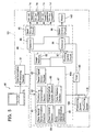
- FIG. 5 is a schematic block view of a control structure of the ink jet printer 101.
- the ink jet printer 101 has a communication processing section 91.
- the communication processing section 91 is connected with a PC (personal computer) 90.
- the communication processing section 91 receives print data files output from the PC 90.
- the ink jet printer 101 prints the printing paper in accordance with the content of the print data.
- the communication processing section 91 is connected with the controller 60.
- the controller 60 has a main control section 60a, an image memory 86, a flushing control circuit 87, selectors 88 and 89, a head driving circuit 95, a motor driving circuit 96, etc.
- the controller 60 is provided with a CPU (Central Processing Unit), a ROM (Read Only Memory), and a RAM (Random Access Memory) (these are not shown).
- the CPU executes various processes.
- the ROM stores control programs to be executed by the CPU, and stores data used in the execution of these control programs.
- the RAM temporarily stores data generated by various processes.
- the main control section 60a has a data amount determination section 61, a positioning determination section 62, a reset signal output section 63, a head control section 64, a transportation control section 65, a print termination determination section 66, and a data deletion section 67, these being constituted by the CPU, the ROM, and the RAM. The specific functions of these sections will be described later.
- the positioning sensors 109 and 110 and a timer 85 are connected with the main control section 60a.
- the positioning sensors 109 and 110 and the timer 85 are disposed to the exterior of the controller 60.
- the positioning sensors 109 and 110 output the detection signals to the main control section 60a while they are detecting the printing paper.
- the timer 85 starts, resets, or restarts based on signals output from the reset signal output section 63.
- the selectors 88 and 89 are connected with the timer 85. Time measured by the timer 85 is input to the selectors 88 and 89.
- the selector 88 outputs a signal to the head driving circuit 95 when the time measured by the timer 85 exceeds a predetermined time.
- the head driving circuit 95 drives the ink jet heads 1a to 1d.
- the selector 89 outputs a signal to the motor driving circuit 96 when the time measured by the timer 85 exceeds the predetermined time.
- the motor driving circuit 96 drives the motor 142.
- the main control section 60a is connected with the image memory 86 and the flushing control circuit 87.
- the image memory 86 and the flushing control circuit 87 are disposed within the controller 60.
- the image memory 86 stores the print data received by the communication processing section 91.
- the print data received by the communication processing section 91 is stored in the image memory 86 via the main control section 60a.
- the flushing control circuit 87 controls, via the selectors 88 and 89, the head driving circuit 95 and the motor driving circuit 96 to perform the flushing action (to be described).
- the image memory 86 and the flushing control circuit 87 are connected with the selectors 88 and 89.
- the selector 88 is set so that, in the case where the time measured by the timer 85 has not reached the predetermined time, the selector 88 outputs the print data stored in the image memory 86 to the head driving circuit 95.
- the head driving circuit 95 can thus drive the ink jet heads 1 to execute the printing action in accordance with this print data.
- the selector 88 is set so that, in the case where the time measured by the timer 85 has reached the predetermined time, the selector 88 outputs flushing data supplied from the flushing control circuit 87 to the head driving circuit 95.
- the head driving circuit 95 can thus drive the ink jet heads 1 to execute the flushing action.
- the selector 89 can output the print data stored in the image memory 86 to the motor driving circuit 96.
- the motor driving circuit 96 can thus drive the motor 142 to transport the printing paper in accordance with this print data.
- the selector 89 is set so that, in the case where the time measured by the timer 85 has reached the predetermined time, the selector 89 outputs the flushing data supplied from the flushing control circuit 87 to the motor driving circuit 96.
- the motor driving circuit 96 can thus drive the motor 142 to execute the flushing action.
- the data amount determination section 61 determines whether the print data received by the communication processing section 91 has reached an amount of data corresponding to ten lines of the printing paper.
- the positioning determination section 62 determines the position of the printing paper based on the results detected by the positioning sensors 109 and 110.
- the positioning determination section 62 determines whether the printing paper is in the first, second, or third position.
- the reset signal output section 63 outputs a signal to the timer 85.
- the reset signal output section 63 outputs, for example, a reset signal to the timer 85 every time that ten lines of printing have been completed. The value measured by the timer 85 is thus reset to zero, and the timer 85 restarts.
- the reset signal output section 63 may equally well output a signal to the selectors 88 and 89 to nullify the determination of these selectors 88 and 89 (i.e. the determination that the time measured by the timer 85 has exceeded the predetermined time).
- the head control section 64 controls the head driving circuit 95 via the selector 88.
- the head control section 64 controls the head driving circuit 95 when the ink jet heads 1 are being driven in conditions where the flushing action is not to be executed.
- the control for the flushing action is executed by the flushing control circuit 87.
- the transportation control section 65 controls the motor driving circuit 96 via the selector 89.
- the transportation control section 65 controls the motor driving circuit 96 when the printing paper is being transported in conditions where the flushing action is not to be executed.
- the control for the flushing action is executed by the flushing control circuit 87.
- the print termination determination section 66 determines whether printing that corresponds to one printing page has been completed. In the present representative embodiment, an amount of data corresponding to fifty lines has been adopted as the quantity of print data of one printing page.
- the data deletion section 67 deletes the print data corresponding to the fifty lines that is being stored in the image memory 86. Otherwise, the data deletion section 67 may delete all the print data include in the single print data file that is being stored in the image memory 86 in the case where all of the print data have been printed.
- the positioning sensors 109 and 110 are used in the present representative embodiment. However, it is instead possible to use an encoder that counts the number of rotations of the belt roller 106 or the motor 142. This encoder is disposed close to a rotary shaft of the belt roller 106 or the motor 142. The encoder counts the number of rotations of the belt roller 106 or the motor 142, and outputs this count number to the selectors 88 and 89. In this case, the selectors 88 and 89 are configured such that they use the count number from the encoder to determine whether the printing paper is in the first, second, or third position. With this configuration, the positioning sensors 109 and 110 are not required, and consequently the configuration of the ink jet printer can be simplified. Manufacturing costs can therefore be reduced.
- the ink jet printer 101 follows control programs so that the controller 60 controls hardware.
- the description is given using an example in which one print data file output from the PC 90 contains print data corresponding to one page of printing paper (i.e. fifty lines).
- each of the ink jet heads 1a to 1d has nozzles corresponding to ten lines.
- Each of the ink jet heads 1a to 1d is capable of simultaneously printing ten lines of print data.
- the ink jet printer 101 receives the print data file output from the PC 90 (S1).
- This print data file contains print data corresponding to fifty lines of printing.
- the communication processing section 91 outputs this received print data to the main control section 60a.
- the print data that has been output from the communication processing section 91 is input to the main control section 60a.
- the main control section 60a stores this print data in the image memory 86.
- the flushing control circuit 87 controls the motor driving circuit 96 via the selector 89.
- the motor driving circuit 96 thus causes the transportation belt 108 to rotate to a position where the recess 102 (see FIG. 1 ) is facing the ink discharging face 2a of the ink jet head 1a.
- the flushing control circuit 87 controls the head driving circuit 95 via the selector 88.
- the head driving circuit 95 thus drives the ink jet head 1a to discharge ink from all the nozzles.
- the recess 102 receives the ink that is discharged from the ink jet head 1a.
- the transportation belt 108 is rotated until the recess 102 is facing the ink discharging face 2b of the ink jet head 1b. Ink is discharged from all the nozzles of the ink jet head 1b. Similarly, the ink jet head 1c discharges ink towards the recess 102, and the ink jet head 1d also discharges ink towards the recess 102. In the present representative embodiment, flushing is performed of all the ink jet heads 1a to 1d. However, in the case where printing of a single color (black, for example) is executed, flushing may be performed of only the ink jet head that is being used. In the process of S3, the printing paper is fed along the transportation path 200 when the flushing action has been executed.
- This process is executed by means of the controller 60 driving a motor connected with the rollers 105a and 105b (see FIG. 1 ).
- the printing paper is thus positioned facing the ink discharging face 2a of the ink jet head 1a. In this state, the printing paper is not facing the ink discharging faces 2b to 2d.
- the timer 85 starts at the time when the flushing action terminates.
- This process is executed by the reset signal output section 63.
- the reset signal output section 63 outputs a signal to the timer 85. When the timer 85 receives the signal, the timer 85 starts.
- the printing action is executed in S6.
- the head control section 64 controls the head driving circuit 95 via the selector 88.
- the head driving circuit 95 drives the ink jet heads 1a to 1d. Ink is discharged from the ink jet heads 1a to 1d. In the case where, for example, the first ten lines (line 1 to line 10) of the printing paper are facing the ink discharging face 2a, cyan ink is discharged from the ink discharging face 2a towards the portion of the printing paper corresponding to the first ten lines.
- the reset signal output section 63 outputs the reset signal to the timer 85.
- the value measured by the timer 85 thus returns to zero, and the timer 85 is restarted.
- the ink discharging face 2a discharges cyan ink towards the portion of the printing paper corresponding to line 11 to line 20.
- the ink discharging face 2b discharges magenta ink towards the portion of the printing paper corresponding to the first ten lines.
- the ink discharging face 2a discharges cyan ink towards the portion of the printing paper corresponding to line 21 to line 30.
- the ink discharging face 2b discharges magenta ink towards the portion of the printing paper corresponding to line 11 to line 20.
- the ink discharging face 2c discharges yellow ink towards the portion of the printing paper corresponding to the first ten lines.
- the ink discharging face 2a discharges cyan ink towards the portion of the printing paper corresponding to line 31 to line 40.
- the ink discharging face 2b discharges magenta ink towards the portion of the printing paper corresponding to line 21 to line 30.
- the ink discharging face 2c discharges yellow ink towards the portion of the printing paper corresponding to line 11 to line 20.
- the ink discharging face 2d discharges black ink towards the portion of the printing paper corresponding to the first ten lines.
- Four color printing has thus been performed of the first ten lines of the printing paper.
- Color printing is performed on the fifty lines of the printing paper by executing the process of S6 with respect to the following groups often lines.
- S7 it is determined whether the printing of fifty lines (one page of printing paper) has been completed.
- the print termination determination section 66 is provided with a counter that counts, for example, the number of times that ten lines have been completed. It can be determined whether the printing of fifty lines has been completed by reading the count value of the counter.
- the process proceeds to S8.
- S8 the printing page is ejected to the paper ejection part 112. This process is executed by the transportation control section 65 controlling the motor driving circuit 96 via the selector 89.
- the print data is deleted that corresponds to fifty lines and is being stored in the image memory 86.
- This process is executed by the data deletion section 67. In the case where the printing of the fifty lines has not been completed (NO in S7), the process returns to S4. Thereupon, it is determined whether the print data of the next ten lines of print data has been received.
- FIG. 7 shows positional relationships between the ink jet head 1 and the printing paper P.
- the four ink jet heads 1a to 1d are not shown separately, but are instead shown jointly as a single member.
- FIG. 7 (a) shows a state where the anterior end of the printing paper P has passed the positioning sensor 109 and has not passed the positioning sensor 110 (i.e. the first position).
- FIG. 7 (b) shows a state where the printing paper P is facing the entirety of the ink discharging face 2 (i.e. the second position).
- FIG. 7 shows positional relationships between the ink jet head 1 and the printing paper P.
- the four ink jet heads 1a to 1d are not shown separately, but are instead shown jointly as a single member.
- FIG. 7 (a) shows a state where the anterior end of the printing paper P has passed the positioning sensor 109 and has not passed the positioning sensor 110 (i.e. the first position).
- FIG. 7 (b) shows a state where the printing paper P is facing the entirety of the ink
- FIG. 7 (c) shows a state where a posterior end of the printing paper P has passed the positioning sensor 109 and has not passed the positioning sensor 110 (i.e. the third position).
- the positioning determination section 62 determines, based on the results detected by the positioning sensors 109 and 110, whether the printing paper P is in the first, second, or third position (see FIGS. 7 (a) to (c) ). In the case where it is determined that the printing paper P is in the first position ( FIG. 7 (a) ), the process proceeds to S 12.
- the flushing control circuit 87 controls the motor driving circuit 96 via the selector 89. The printing paper P is thus transported to the second position.
- the recess 102 of the belt 108 can therefore be cleaned less frequently.
- the process proceeds to S 14.
- the printing paper that has received the flushed ink is ejected.
- the transportation control section 65 controls the motor driving circuit 96 via the selector 89.
- the motor 142 thus rotates, and the printing paper is ejected.
- the process proceeds to S15.
- the printing paper is ejected to the paper ejection part 112.
- the transportation control section 65 controls the motor driving circuit 96 via the selector 89.
- the motor 142 therefore rotates, and the printing paper is ejected.
- the head control section 64 controls the head driving circuit 95 via the selector 88, and the transportation control section 65 controls the motor driving circuit 96 via the selector 89.
- the reset signal output section 63 outputs the reset signal. The timer 85 is thus reset, and is restarted. The process proceeds to S7.
- FIG. 8 is an example of a time chart in the case where the flow chart of FIG. 6 is executed.
- FIG. 8 shows the following items: the print data input, printing action, transportation action, flushing, and time.
- the description is given for the case where one print data file contains print data corresponding to fifty lines (one page).
- the first ten lines of print data D1, out of the fifty lines of print data output from the PC 90, are received by the communication processing section 91.
- a control signal is output from the main control section 60a to the flushing control circuit 87.
- the flushing control circuit 87 drives the motor driving circuit 96.
- the motor driving circuit 96 causes the motor 142 to rotate.
- the transportation belt 108 executes a transportation action FM1 so that the recess 102 of the transportation belt 108 is sequentially located so as to face the ink discharging faces 2a to 2d of the ink jet heads 1a to 1d.
- the flushing control circuit 87 drives the head driving circuit 95.
- ink discharging face 2a is facing the recess 102
- ink is discharged from the ink discharging face 2a.
- ink is discharged sequentially from the ink discharging faces 2b to 2d when these are facing the recess 102.
- a flushing action F1 is thus executed.
- a transportation action M1 to supply the printing paper is performed within the transportation path 200.
- This transportation action M1 is executed by driving the motor connected with the rollers 105a and 105b.
- the timer 85 begins measurement (T0).
- the data amount determination section 61 determines that the first ten lines of print data D1 have been received. At this juncture, the measured time T0 is compared with the predetermined time T (see S5 of FIG. 6 ). In the present representative embodiment, T0 is smaller than T.
- the head control section 64 controls the head driving circuit 95, thus performing a printing action P1 in which the ink jet head 1a prints the print data D1.
- the transportation control section 65 controls the motor driving circuit 96 to cause the motor 142 to rotate.
- a transportation action M2 is thus performed in which the printing paper is moved by an amount corresponding to ten lines.
- the communication processing section 91 receives print data D2. This print data D2 is the print data corresponding to line 11 to line 20.
- the timer 85 measures time T1 from the completion of the printing action P1.
- the data amount determination section 61 determines that the print data D2 has been received.
- the measured time T1 is compared with the predetermined time T. In the present representative embodiment, T1 is smaller than T.
- the head control section 64 controls the head driving circuit 95, thus executing a printing action P2.
- the ink jet head 1a prints the portion of the printing paper corresponding to line 11 to line 20 based on the print data D2.
- the ink jet head 1b prints the portion of the printing paper corresponding to the first ten lines based on the print data D1.
- the transportation control section 65 controls the motor driving circuit 96, thus causing the transportation motor 142 to rotate.
- the transportation action M2 is thus performed in which the printing paper is moved by an amount corresponding to ten lines.
- the portion corresponding to line 21 to line 30 is thus transported to a position facing the ink discharging face 2a. Moreover, while P2 and M2 immediately after P2 are being executed, the communication processing section 91 receives print data D3. This print data D3 is the print data corresponding to line 21 to line 30. When the printing action P2 has been completed, the reset signal is output from the printing reset signal output section 63. The timer 85 is restarted. The timer 85 measures time T2.
- the positioning determination section 62 determines the position of the printing paper based on the results detected by the positioning sensors 109 and 110 (S11 in FIG. 5 ). At this juncture, the portion of the printing paper corresponding to line 21 to line 30 is facing the ink discharging face 2a. That is, the portion of the printing paper corresponding to the first ten lines is facing the ink discharging face 2c. The anterior end of the printing paper has thus not reached the positioning sensor 110, and the positioning determination section 62 determines that the printing paper is in the first position. The printing paper is then transported (see S12 of FIG. 5 ).
- This process is executed by the flushing control circuit 87 controlling the motor driving circuit 96.
- the printing paper is transported to the second position (transportation action FM2). While the transportation action FM2 is being performed, the communication processing section 91 receives print data D4.
- the print data D4 is the print data corresponding to line 31 to line 40.
- the flushing control circuit 87 controls the head driving circuit 95. Ink is thus discharged towards the printing paper from the ink jet heads 1a to 1d (flushing action F2).
- the transportation control section 65 controls the motor driving circuit 96. The transportation motor 142 therefore rotates. The printing paper onto which ink has been discharged is ejected to the paper ejection part 112 (transportation action M3).
- the transportation control section 65 controls the motor driving circuit 96 and a new printing paper is supplied (transportation action M1).
- the communication processing section 91 receives the print data D4 and D5 while FM2, F2, M3, and M1 are being executed. D5 is the print data corresponding to line 41 to line 50.
- the reception of the print data D1 to D4 is completed while the transportation action M1 immediately after the transportation action M3 is being executed.
- the print data D1 to D4 has been stored in the image memory 86.
- the printing of the print data D1 to D4 can thus be executed.
- the printing action P1 of the print data D1 is executed.
- the transportation action M2 is performed in which the printing paper is moved by an amount corresponding to ten lines.
- the printing action P2 in which the ink jet head 1a prints the portion of the printing paper corresponding to line 11 to line 20 based on the print data D2 is executed.
- the ink jet head 1b prints the portion of the printing paper corresponding to first ten lines based on the print data D1.
- the transportation action M2 is performed in which the printing paper is moved by an amount corresponding to ten lines.
- the printing action P3 is executed.
- the ink jet head 1a prints the portion of the printing paper corresponding to line 21 to line 30 based on the print data D3.
- the ink jet head 1b prints the portion of the printing paper corresponding to line 11 to line 20 based on the print data D2.
- the ink jet head 1c prints the portion of the printing paper corresponding to first ten lines based on the print data D1.
- the transportation action M2 is performed in which the printing paper is moved by an amount corresponding to ten lines.
- the printing action P4 is executed.
- the ink jet head 1a prints the portion of the printing paper corresponding to line 31 to line 40 based on the print data D4.
- the ink jet head 1b prints the portion of the printing paper corresponding to line 21 to line 30 based on the print data D3.
- the inkjet head 1c prints the portion of the printing paper corresponding to line 11 to line 20 based on the print data D2.
- the ink jet head 1d prints the portion of the printing paper corresponding to first ten lines based on the print data D1.
- the transportation action M2 is performed in which the printing paper is moved by an amount corresponding to ten lines. The determination whether the predetermined time has elapsed is not performed while these printing actions P1 to P4 are being performed. When the printing actions P1 to P4 has been completed, the portion of the printing paper corresponding to first ten lines has been full color printed.
- the ink jet head 1a prints the portion of the printing paper corresponding to line 41 to line 50 based on the print data D5.
- the ink jet head 1b prints the portion of the printing paper corresponding to line 31 to line 40 based on the print data D4.
- the ink jet head 1c prints the portion of the printing paper corresponding to line 21 to line 30 based on the print data D3.
- the ink jet head 1d prints the portion of the printing paper corresponding to line 11 to line 20 based on the print data D2.
- the ink jet head 1b prints the portion of the printing paper corresponding to line 41 to line 50 based on the print data D5.
- the ink jet head 1c prints the portion of the printing paper corresponding to line 31 to line 40 based on the print data D4.
- the ink jet head 1d prints the portion of the printing paper corresponding to line 21 to line 30 based on the print data D3.
- the printing action P7 is performed.
- the ink jet head 1c prints the portion of the printing paper corresponding to line 41 to line 50 based on the print data D5.
- the ink jet head 1d prints the portion of the printing paper corresponding to line 31 to line 40 based on the print data D4.
- the printing actions P7 has been completed, the portion of the printing paper corresponding to line 1 to line 40 has been full color printed.
- the transportation action M2 is performed.
- the printing action P8 is performed.
- the ink jet head 1d prints the portion of the printing paper corresponding to line 41 to line 50 based on the print data D5.
- the portion of the printing paper corresponding to line 1 to line 50 has been full color printed.
- the printing actions P5 to P9 are executed based on the print data D2 to D5 which had been already received. Therefore, the determination whether the time measured by the timer 85 is within the predetermined time is not performed while printing actions P5 to P9 are being performed.
- the print termination determination section 66 determines that the printing of fifty lines of print data has been completed.
- the transportation control section 65 controls the motor driving circuit 96, and the motor 142 therefore rotates.
- a transportation action M4 is performed in which the printing paper is transported to the paper ejection part 112. Printing by the ink jet printer 101 is thus completed.
- the ink jet printer 101 of the present representative embodiment has been described in detail.
- This ink jet printer 101 does not begin printing only after having received all the print data included in one print data file (this corresponding to fifty lines of printing in the present representative embodiment). Instead, the ink jet printer 101 begins printing after having received print data corresponding to ten lines of printing.
- the time required for printing can be reduced. In conditions such as those shown in FIG. 8 , for example, the flushing action is performed after printing has begun. It might seem that a longer time would be required for printing in this case. However, two rounds of the printing action P1 have been performed in FIG. 8 before all the print data D1 to D5 has been received. As a result, the time required for printing can be made shorter than in the case where printing begins only after all the print data D1 to D5 has been received.
- the printing action is not restarted of a partially printed printing paper in the case where a predetermined amount of print data cannot be received within the predetermined time period (T). Printing that has variations in printing quality can thus be prevented.
- the positioning determination section 62 determines the position of the printing paper based on the results detected by the positioning sensors 109 and 110. When the printing paper is in the first or the second position, the flushing action is performed in which ink is discharged toward the printing paper. It is thus possible to reduce the number of times that the flushing action is performed onto the recess 102 of the transportation belt 108, and the transportation belt 108 therefore requires less frequent cleaning.
- the partially printed printing paper is ejected.
- the ink is discharged toward the transportation belt 108.
- the flushing action prevents printing in which viscous ink is discharged. Furthermore, the flushing action prevents the ink from being discharged in an inadequate manner. A deterioration in printing quality can thus be prevented. Printing is performed on new printing paper when the flushing action has been completed. As a result, high quality printing can be executed.
Landscapes
- Ink Jet (AREA)
Claims (21)
- Tintenstrahldrucker (101) zum Ausführen einer Drucktätigkeit gegen ein Druckmedium auf der Grundlage von Druckdaten, die von einer externen Vorrichtung (90) ausgegeben werden, die mit dem Tintenstrahldrucker (101) kommunizieren kann, wobei der Tintenstrahldrucker (101) aufweist:einen Tintenstrahlkopf (1a, 1b, 1c, 1d) zum Ausführen der Drucktätigkeit, bei der Tinte zu dem Druckmedium ausgegeben wird;eine Transportvorrichtung (103) zum Transportieren des Druckmediums; undeine Steuerung (60), die aufgebaut ist zum Steuern des Tintenstrahlkopfs (1a, 1b, 1c, 1d) zum Ausführen der Drucktätigkeit, wenn der Tintenstrahldrucker (101) das Empfangen eines vorbestimmten Betrags von Druckdaten beendet hat;wobei die Steuerung (60) aufgebaut ist zum Verhindern, dass der Tintenstrahldrucker (1a, 1b, 1c, 1d) die Drucktätigkeit gegen ein teilweise bedrucktes Druckmedium ausführt, und zum Steuern der Transportvorrichtung (103) zum Ausstoßen des Druckmediums in einem Fall, in dem eine Zeit seit der letzten Drucktätigkeit eine vorbestimmte Zeit überschritten hat; undin einem Fall, in dem der Tintenstrahldrucker (101) das Empfangen des vorbestimmten Betrags von Druckdaten innerhalb der vorbestimmten Zeit seit der letzten Drucktätigkeit beendet hat, die Steuerung (60) weiter angepasst ist zum Steuern des Tintenstrahlkopfs (1a, 1b, 1c, 1d) zum Ausführen der Drucktätigkeit gegen das teilweise bedruckte Druckmedium.
- Tintenstrahldrucker (101) nach Anspruch 1,
bei dem der vorbestimmte Betrag der Druckdaten ein Teil von Druckdaten ist, die in einer Druckdatendatei enthalten sind. - Tintenstrahldrucker (101) nach Anspruch 2,
der so aufgebaut ist, dass der vorbestimmte Betrag von Druckdaten jedes Mal variiert wird, wenn der Tintenstrahldrucker (101) den vorbestimmten Betrag von Druckdaten empfängt. - Tintenstrahldrucker (101) nach Anspruch 2,
der so aufgebaut ist, dass der vorbestimmte Betrag von Druckdaten jedes Mal fixiert wird, wenn der Tintenstrahldrucker (101) den vorbestimmten Betrag von Druckdaten empfängt. - Tintenstrahldrucker nach einem der Ansprüche 1 bis 4, bei dem in dem Fall, in dem die Zeit seit der letzten Drucktätigkeit die vorbestimmte Zeit überschritten hat, die Steuerung (60) angepasst ist zum Steuern des Tintenstrahlkopfs (1a, 1b, 1c, 1d) zum Ausführen einer Spültätigkeit, bei der Tinte so ausgegeben wird, dass eine Tintenausgabefähigkeit des Tintenstrahlkopfs (1a, 1b, 1c, 1d) wiedergewonnen wird.
- Tintenstrahldrucker (101) nach Anspruch 5,
bei dem die Steuerung (60) aufgebaut ist zum Steuern des Tintenstrahlkopfs (1a, 1b, 1c, 1d) zum Ausführen der Spültätigkeit, bei der Tinte nicht auf der Grundlage von Druckdaten ausgegebenen wird. - Tintenstrahldrucker (101) nach Anspruch 5 oder 6,
bei dem die Steuerung (60) angepasst ist zum Steuern des Tintenstrahlkopfs (1a, 1b, 1c, 1d) zum Ausführen der Spültätigkeit, bei der Tinte zu dem teilweise bedruckten Druckmedium ausgegeben wird und
zum Steuern der Transportvorrichtung (103) zum Ausstoßen des Druckmediums nach der Spültätigkeit. - Tintenstrahldrucker (101) nach Anspruch 5 oder 6,
bei dem, nachdem das teilweise bedruckte Druckmedium ausgestoßen worden ist, die Steuerung (60) aufgebaut ist zum Steuern des Tintenstrahlkopfs (1a, 1b, 1c, 1d) zum Ausführen der Spültätigkeit, bei der Tinte zu der Transportvorrichtung (103) ausgegeben wird. - Tintenstrahldrucker (101) nach Anspruch 8,
bei dem die Transportvorrichtung (103) einen sich bewegenden Riemen (108) aufweist, der Kontakt mit dem Druckmedium herstellen kann, und
die Steuerung (60) angepasst ist zum Steuern des Tintenstrahlkopfs (1a, 1b, 1c, 1d) zum Ausführen der Spültätigkeit, bei der Tinte zu dem sich bewegenden Riemen (108) ausgegeben wird. - Tintenstrahldrucker (101) nach Anspruch 5 oder 6, weiter mit:einem Positionssensor (109, 110), der eine Position des teilweise bedruckten Druckmediums erfaßt,wobei die Steuerung (60) aufgebaut ist zum Steuern des Tintenstrahlkopfs (1a, 1b, 1c, 1d) zum Ausführen der Spültätigkeit, bei der Tinte zu dem teilweise bedruckten Druckmedium ausgegeben wird, und Steuern der Transportvorrichtung (103) zum Ausstoßen des Druckmediums nach der Spültätigkeit in einem Fall, in dem die Position des Druckmediums eine zugewandte Position ist, an der alle Tintenausgabedüsen des Tintenstrahlkopfs (1a, 1b, 1c, 1d) dem Druckmedium zugewandt sind, oder in einem Fall, in dem die Position des Druckmediums stromaufwärts von der zugewandten Position ist und nur einige des Tintenausgabedüsen dem Druckmedium zugewandt sind, unddie Steuerung (60) weiter aufgebaut ist zum Steuern des Tintenstrahlkopfs (1a, 1b, 1c, 1d) zum Ausführen der Spültätigkeit, bei der Tinte zu der Transportvorrichtung (103) ausgegeben wird, nachdem das teilweise bedruckte Druckmedium ausgestoßen worden ist in einem Fall, in dem die Position des Druckmediums stromabwärts von der zugewandten Position ist und nur einige der Tintenausgabedüsen dem Druckmedium zugewandt sind.
- Tintenstrahldrucker (101) nach einem der Ansprüche 2 bis 4, weiter mit:einem Speicher (86), der angepasst ist zum Speichern der Druckdaten, die von der externen Vorrichtung (90) ausgegeben sind,wobei die Steuerung (60) aufgebaut ist zum Löschen aus dem Speicher (86) all der Druckdaten, die in der Druckdatendatei enthalten sind, nachdem all die Druckdaten, die in der Druckdatendatei enthalten sind, gedruckt worden sind.
- Tintenstrahldrucker (101) nach Anspruch 11,
bei dem in dem Fall, in dem die Zeit seit der letzten Drucktätigkeit die vorbestimmte Zeit überschritten hat, die Steuerung (60) angepasst ist zum Steuern des Tintenstrahlkopfs (1a, 1b, 1c, 1d) zum Ausführen der Drucktätigkeit gegen ein neues Druckmedium, wobei die Drucktätigkeit auf den Druckdaten beruht, die in dem Speicher (86) gespeichert sind. - Tintenstrahldrucker (101) nach einem der Ansprüche 5 bis 10, bei dem der Tintenstrahldrucker (101) ein Liniendrucker ist.
- Verfahren des Steuerns eines Tintenstrahldruckers (101), der eine Drucktätigkeit gegen ein Druckmedium auf der Grundlage von Druckdaten ausführt, die von einer externen Vorrichtung (90) ausgegeben werden, die mit dem Tintenstrahldrucker (101) kommunizieren kann, wobei das Verfahren aufweist:einen Schritt des Steuerns des Tintenstrahldruckers (101) zum Ausführen der Drucktätigkeit, wenn der Tintenstrahldrucker (101) Empfangen eines vorbestimmten Betrags von Druckdaten beendet hat;einen Schritt des Verhinderns, dass der Tintenstrahldruckers (101) die Drucktätigkeit gegen ein teilweise bedrucktes Druckmedium in einem Fall ausführt, in dem eine Zeit seit der letzten Drucktätigkeit eine vorbestimmte Zeit überschritten hat;einen Schritt des Steuerns des Tintenstrahldruckers (101) zum Ausstoßen des teilweise bedruckten Druckmediums; undeinen Schritt des Steuerns des Tintenstrahlkopfs (1a, 1b, 1c, 1d) zum Ausführen der Drucktätigkeit gegen das teilweise bedruckte Druckmedium in einem Fall, in dem der Tintenstrahldrucker (101) Empfangen des vorbestimmten Betrags von Druckdaten innerhalb der vorbestimmten Zeit seit der letzten Drucktätigkeit beendet hat.
- Verfahren nach Anspruch 14, weiter mit:einem Schritt des Steuerns des Tintenstrahldruckers (101) zum Ausführen einer Spültätigkeit, bei der Tinte so ausgegeben wird, dass eine Tintenausgabefähigkeit wiedergewonnen wird in einem Fall, in dem die Zeit seit der letzten Drucktätigkeit die vorbestimmte Zeit überschritten hat.
- Verfahren nach Anspruch 14 oder 15,
bei dem der vorbestimmte Betrag von Druckdaten ein Teil von Druckdaten ist, die in einer Druckdatendatei enthalten sind, und
der vorbestimmte Betrag von Druckdaten jedes Mal variiert wird, wenn der Tintenstrahldrucker (101) den vorbestimmten Betrag von Druckdaten empfängt. - Verfahren nach Anspruch 14 oder 15, bei dem der vorbestimmte Betrag von Druckdaten ein Teil von Druckdaten ist, die in einer Druckdatendatei enthalten sind, und
der vorbestimmte Betrag von Druckdaten jedes Mal fixiert wird, wenn der Tintenstrahldrucker (101) den vorbestimmten Betrag von Druckdaten empfängt. - Computerprogrammprodukt, das durch eine Computervorrichtung (60) ausgeführt wird, die auf einem Tintenstrahldrucker (101) angebracht ist, der eine Drucktätigkeit gegen ein Druckmedium auf der Grundlage von Druckdaten ausführt, die von einer externen Vorrichtung (90) ausgegeben werden, die mit dem Tintenstrahldrucker (101) kommunizieren kann, wobei das Computerprogrammprodukt Instruktionen zum Bewirken enthält, dass die Computervorrichtung (60) ausführt:einen Schritt des Steuerns des Tintenstrahldruckers (101) zum Ausführen der Drucktätigkeit, wenn der Tintenstrahldrucker (101) Empfangen eines vorbestimmten Betrags von Druckdaten beendet hat;einen Schritt des Verhinderns des Tintenstrahldruckers (101), dass Drucktätigkeit gegen ein teilweise bedrucktes Druckmedium in einem Fall ausgeführt wird, in dem eine Zeit seit einer letzten Drucktätigkeit ein vorbestimmte Zeit überschritten hat;einen Schritt des Steuerns des Tintenstrahldruckers (101) zum Ausstoßen des teilweise bedruckten Druckmediums; und einen Schritt des Steuerns des Tintenstrahlkopfs (1a, 1b, 1c, 1d) zum Ausführen des Drucktätigkeit gegen das teilweise bedruckten Druckmedium in einem Fall, in dem der Tintenstrahldrucker (101) Empfangen des vorbestimmten Betrags von Druckdaten innerhalb der vorbestimmten Zeit seit der letzten Drucktätigkeit beendet hat.
- Computerprogrammprodukt nach Anspruch 18 mit Instruktionen zum Bewirken, dass die Computervorrichtung (60) weiter ausführt:einen Schritt des Steuerns des Tintenstrahldruckers (101) zum Ausführen einer Spültätigkeit, bei der Tinte so ausgegeben wird, dass eine Tintenausgabefähigkeit in einem Fall wiedergewonnen wird, in dem die Zeit seit der letzten Drucktätigkeit die vorbestimmte Zeit überschritten hat.
- Computerprogrammprodukt nach Anspruch 18 oder 19,
bei dem der vorbestimmte Betrag von Druckdaten ein Teil von Druckdaten ist, die in einer Druckdatendatei enthalten sind, und
der vorbestimmte Betrag von Druckdaten jedes Mal variiert wird, wenn der Tintenstrahldrucker (101) den vorbestimmten Betrag von Druckdaten empfängt. - Computerprogrammprodukt nach Anspruch 18 oder 19,
bei dem der vorbestimmte Betrag von Druckdaten ein Teil von Druckdaten ist, die in einer Druckdatendatei enthalten sind, und
der vorbestimmte Betrag von Druckdaten jedes Mal fixiert wird, wenn der Tintenstrahldrucker (101) den vorbestimmten Betrag von Druckdaten empfängt.
Applications Claiming Priority (1)
| Application Number | Priority Date | Filing Date | Title |
|---|---|---|---|
| JP2004189510A JP4140566B2 (ja) | 2004-06-28 | 2004-06-28 | プリンタ、プリンタの制御方法及びプリンタにおいて実行されるプログラム |
Publications (3)
| Publication Number | Publication Date |
|---|---|
| EP1632356A1 EP1632356A1 (de) | 2006-03-08 |
| EP1632356A3 EP1632356A3 (de) | 2006-07-19 |
| EP1632356B1 true EP1632356B1 (de) | 2010-09-01 |
Family
ID=35005828
Family Applications (1)
| Application Number | Title | Priority Date | Filing Date |
|---|---|---|---|
| EP05254026A Ceased EP1632356B1 (de) | 2004-06-28 | 2005-06-28 | Tintenstrahldrucker, Steuerungverfahren und Computerprogrammprodukt dafür |
Country Status (4)
| Country | Link |
|---|---|
| US (1) | US7677684B2 (de) |
| EP (1) | EP1632356B1 (de) |
| JP (1) | JP4140566B2 (de) |
| DE (1) | DE602005023245D1 (de) |
Families Citing this family (12)
| Publication number | Priority date | Publication date | Assignee | Title |
|---|---|---|---|---|
| US7360853B2 (en) * | 2004-03-04 | 2008-04-22 | Fujifilm Dimatix, Inc. | Morphology-corrected printing |
| JP5014599B2 (ja) * | 2005-06-23 | 2012-08-29 | 大日本スクリーン製造株式会社 | 印刷システム、印刷装置のコントローラ、印刷処理の実行方法、およびプログラム |
| JP4788280B2 (ja) * | 2005-10-19 | 2011-10-05 | 富士ゼロックス株式会社 | 液体吐出ヘッドの駆動装置及び液体吐出装置 |
| US20070206038A1 (en) * | 2006-03-03 | 2007-09-06 | Richard Baker | Ink jet printing with multiple conveyors |
| US7845790B2 (en) * | 2006-04-07 | 2010-12-07 | Fujifilm Dimatix, Inc. | Ink jet printing |
| US7524050B2 (en) * | 2006-04-11 | 2009-04-28 | Fujifilm Dimatix, Inc. | Ink jet printing |
| JP5061927B2 (ja) * | 2008-01-29 | 2012-10-31 | ブラザー工業株式会社 | 液体吐出装置 |
| JP2010208255A (ja) * | 2009-03-12 | 2010-09-24 | Seiko Epson Corp | 液体噴射装置および液体噴射装置の駆動制御方法 |
| US11241835B2 (en) * | 2013-09-27 | 2022-02-08 | The Western Union Company | System and method for remote production of financial instruments |
| US9676194B2 (en) | 2014-09-11 | 2017-06-13 | SCREEN Holdings Co., Ltd. | Inkjet printing method and inkjet printing apparatus |
| JP6575247B2 (ja) * | 2015-09-09 | 2019-09-18 | ブラザー工業株式会社 | 液体吐出装置 |
| JP6962005B2 (ja) * | 2017-05-26 | 2021-11-05 | 富士フイルムビジネスイノベーション株式会社 | 不吐出抑制装置、印刷指示装置、インクジェットヘッド駆動回路及びプログラム |
Family Cites Families (10)
| Publication number | Priority date | Publication date | Assignee | Title |
|---|---|---|---|---|
| JPH06101777B2 (ja) * | 1982-09-22 | 1994-12-12 | キヤノン株式会社 | 記録装置 |
| JPH01206058A (ja) * | 1988-02-15 | 1989-08-18 | Tokyo Electric Co Ltd | 印字装置 |
| EP0372810A3 (de) * | 1988-12-02 | 1991-07-10 | Spectra-Physics, Inc. | Farbstrahldrucker |
| JPH0596826A (ja) | 1991-10-11 | 1993-04-20 | Tokyo Electric Co Ltd | プリンタ |
| KR0122535B1 (ko) | 1993-10-20 | 1997-11-17 | 윤종용 | 전자사진 현상방식 프린터의 잼 제거방법 및 장치 |
| JP3671998B2 (ja) * | 1996-10-31 | 2005-07-13 | セイコーエプソン株式会社 | インクジェット式記録装置 |
| JP3507324B2 (ja) | 1997-12-29 | 2004-03-15 | キヤノンファインテック株式会社 | インクジェット記録装置および回復処理方法並びに回復処理制御プログラムを記憶した記憶媒体 |
| JP2001260370A (ja) | 2000-03-14 | 2001-09-25 | Canon Inc | 画像形成装置及び画像形成方法 |
| JP3774640B2 (ja) * | 2001-05-17 | 2006-05-17 | キヤノン株式会社 | インクジェット記録装置及びインクジェット記録方法 |
| EP1338421B1 (de) | 2002-02-21 | 2007-04-18 | Brother Kogyo Kabushiki Kaisha | Tintenstrahlkopf, Verfahren für dessen Herstellung, und Tintenstrahldrucker |
-
2004
- 2004-06-28 JP JP2004189510A patent/JP4140566B2/ja not_active Expired - Fee Related
-
2005
- 2005-06-28 DE DE602005023245T patent/DE602005023245D1/de not_active Expired - Lifetime
- 2005-06-28 US US11/167,282 patent/US7677684B2/en not_active Expired - Fee Related
- 2005-06-28 EP EP05254026A patent/EP1632356B1/de not_active Ceased
Also Published As
| Publication number | Publication date |
|---|---|
| EP1632356A3 (de) | 2006-07-19 |
| US7677684B2 (en) | 2010-03-16 |
| JP4140566B2 (ja) | 2008-08-27 |
| US20050285894A1 (en) | 2005-12-29 |
| EP1632356A1 (de) | 2006-03-08 |
| JP2006007641A (ja) | 2006-01-12 |
| DE602005023245D1 (de) | 2010-10-14 |
Similar Documents
| Publication | Publication Date | Title |
|---|---|---|
| JP4103668B2 (ja) | 印刷装置、印刷方法、プログラム及び印刷システム | |
| JP5454442B2 (ja) | 液体吐出装置 | |
| US7677684B2 (en) | Ink jet printer, method for controlling an ink jet printer, and computer program product for an ink jet printer | |
| JP4807203B2 (ja) | 両面記録装置及び記録方法 | |
| EP1952991B1 (de) | Tintenstrahldruckvorrichtung und Tintenstrahldruckverfahren | |
| CN101462422A (zh) | 打印装置以及打印装置的控制方法 | |
| US8480198B2 (en) | Image forming apparatus, control method therefor, and medium storing program | |
| US7240983B2 (en) | Inkjet recording apparatus and preliminary discharge control method | |
| EP1312479A1 (de) | Tintenstrahldrucker und reinigungsverfahren für wiederherstellungsverfahren | |
| JP5012650B2 (ja) | 記録装置 | |
| JP2009233891A (ja) | インクジェット記録装置及び方法 | |
| JP3757564B2 (ja) | 印字装置 | |
| JP3783357B2 (ja) | 印字装置 | |
| CN111469552A (zh) | 图像形成装置 | |
| JP2015221512A (ja) | インクジェット記録装置 | |
| JP7380054B2 (ja) | 廃液回収装置、インクジェット記録装置 | |
| JP5581895B2 (ja) | 画像形成装置及びプログラム | |
| US10144221B2 (en) | Printing apparatus and method for determining service life | |
| US20090161180A1 (en) | Printing apparatus and method of controlling printing apparatus | |
| JP2019198964A (ja) | 記録装置 | |
| JP4754933B2 (ja) | 画像形成装置及びプログラム | |
| JP2024143753A (ja) | 記録装置及び記録装置を備えた記録システム | |
| JP2007136769A (ja) | 画像形成装置 | |
| JP2025029233A (ja) | インクジェット記録装置、フラッシング条件決定方法 | |
| JP2025011552A (ja) | インクジェット記録装置、インクジェット記録方法 |
Legal Events
| Date | Code | Title | Description |
|---|---|---|---|
| PUAI | Public reference made under article 153(3) epc to a published international application that has entered the european phase |
Free format text: ORIGINAL CODE: 0009012 |
|
| AK | Designated contracting states |
Kind code of ref document: A1 Designated state(s): AT BE BG CH CY CZ DE DK EE ES FI FR GB GR HU IE IS IT LI LT LU MC NL PL PT RO SE SI SK TR |
|
| AX | Request for extension of the european patent |
Extension state: AL BA HR LV MK YU |
|
| PUAB | Information related to the publication of an a document modified or deleted |
Free format text: ORIGINAL CODE: 0009199EPPU |
|
| PUAF | Information related to the publication of a search report (a3 document) modified or deleted |
Free format text: ORIGINAL CODE: 0009199SEPU |
|
| D17D | Deferred search report published (deleted) | ||
| RA1 | Application published (corrected) |
Date of ref document: 20060308 Kind code of ref document: A2 |
|
| PUAL | Search report despatched |
Free format text: ORIGINAL CODE: 0009013 |
|
| AK | Designated contracting states |
Kind code of ref document: A3 Designated state(s): AT BE BG CH CY CZ DE DK EE ES FI FR GB GR HU IE IS IT LI LT LU MC NL PL PT RO SE SI SK TR |
|
| AX | Request for extension of the european patent |
Extension state: AL BA HR LV MK YU |
|
| 17P | Request for examination filed |
Effective date: 20060901 |
|
| AKX | Designation fees paid |
Designated state(s): DE FR GB |
|
| 17Q | First examination report despatched |
Effective date: 20071106 |
|
| GRAP | Despatch of communication of intention to grant a patent |
Free format text: ORIGINAL CODE: EPIDOSNIGR1 |
|
| GRAS | Grant fee paid |
Free format text: ORIGINAL CODE: EPIDOSNIGR3 |
|
| GRAA | (expected) grant |
Free format text: ORIGINAL CODE: 0009210 |
|
| AK | Designated contracting states |
Kind code of ref document: B1 Designated state(s): DE FR GB |
|
| REG | Reference to a national code |
Ref country code: GB Ref legal event code: FG4D |
|
| REF | Corresponds to: |
Ref document number: 602005023245 Country of ref document: DE Date of ref document: 20101014 Kind code of ref document: P |
|
| PLBE | No opposition filed within time limit |
Free format text: ORIGINAL CODE: 0009261 |
|
| STAA | Information on the status of an ep patent application or granted ep patent |
Free format text: STATUS: NO OPPOSITION FILED WITHIN TIME LIMIT |
|
| 26N | No opposition filed |
Effective date: 20110606 |
|
| REG | Reference to a national code |
Ref country code: DE Ref legal event code: R097 Ref document number: 602005023245 Country of ref document: DE Effective date: 20110606 |
|
| REG | Reference to a national code |
Ref country code: FR Ref legal event code: PLFP Year of fee payment: 12 |
|
| REG | Reference to a national code |
Ref country code: FR Ref legal event code: PLFP Year of fee payment: 13 |
|
| REG | Reference to a national code |
Ref country code: FR Ref legal event code: PLFP Year of fee payment: 14 |
|
| PGFP | Annual fee paid to national office [announced via postgrant information from national office to epo] |
Ref country code: DE Payment date: 20190515 Year of fee payment: 15 |
|
| PGFP | Annual fee paid to national office [announced via postgrant information from national office to epo] |
Ref country code: FR Payment date: 20190522 Year of fee payment: 15 |
|
| PGFP | Annual fee paid to national office [announced via postgrant information from national office to epo] |
Ref country code: GB Payment date: 20190524 Year of fee payment: 15 |
|
| REG | Reference to a national code |
Ref country code: DE Ref legal event code: R119 Ref document number: 602005023245 Country of ref document: DE |
|
| GBPC | Gb: european patent ceased through non-payment of renewal fee |
Effective date: 20200628 |
|
| PG25 | Lapsed in a contracting state [announced via postgrant information from national office to epo] |
Ref country code: GB Free format text: LAPSE BECAUSE OF NON-PAYMENT OF DUE FEES Effective date: 20200628 Ref country code: FR Free format text: LAPSE BECAUSE OF NON-PAYMENT OF DUE FEES Effective date: 20200630 |
|
| PG25 | Lapsed in a contracting state [announced via postgrant information from national office to epo] |
Ref country code: DE Free format text: LAPSE BECAUSE OF NON-PAYMENT OF DUE FEES Effective date: 20210101 |