EP1631097A2 - Installationssystem und Verfahren für ein tragbares Satellitenkommunikationsendgerät des zellularen Endgerätetrennungstyps - Google Patents
Installationssystem und Verfahren für ein tragbares Satellitenkommunikationsendgerät des zellularen Endgerätetrennungstyps Download PDFInfo
- Publication number
- EP1631097A2 EP1631097A2 EP05025713A EP05025713A EP1631097A2 EP 1631097 A2 EP1631097 A2 EP 1631097A2 EP 05025713 A EP05025713 A EP 05025713A EP 05025713 A EP05025713 A EP 05025713A EP 1631097 A2 EP1631097 A2 EP 1631097A2
- Authority
- EP
- European Patent Office
- Prior art keywords
- satellite
- terminal
- portable terminal
- satellite communication
- cellular terminal
- Prior art date
- Legal status (The legal status is an assumption and is not a legal conclusion. Google has not performed a legal analysis and makes no representation as to the accuracy of the status listed.)
- Withdrawn
Links
- 230000001413 cellular effect Effects 0.000 title claims abstract description 185
- 238000004891 communication Methods 0.000 title claims abstract description 177
- 238000000926 separation method Methods 0.000 title claims abstract description 53
- 238000009434 installation Methods 0.000 title claims abstract description 38
- 238000000034 method Methods 0.000 title claims description 27
- 230000005540 biological transmission Effects 0.000 claims abstract description 28
- 239000005357 flat glass Substances 0.000 claims description 41
- 230000004048 modification Effects 0.000 description 25
- 238000012986 modification Methods 0.000 description 25
- 230000006870 function Effects 0.000 description 6
- 239000011521 glass Substances 0.000 description 6
- PEDCQBHIVMGVHV-UHFFFAOYSA-N Glycerine Chemical compound OCC(O)CO PEDCQBHIVMGVHV-UHFFFAOYSA-N 0.000 description 4
- 239000000853 adhesive Substances 0.000 description 3
- 230000001070 adhesive effect Effects 0.000 description 3
- 239000002390 adhesive tape Substances 0.000 description 3
- 238000010586 diagram Methods 0.000 description 3
- 230000005236 sound signal Effects 0.000 description 3
- 230000000694 effects Effects 0.000 description 2
- 239000004973 liquid crystal related substance Substances 0.000 description 2
- IRLPACMLTUPBCL-KQYNXXCUSA-N 5'-adenylyl sulfate Chemical compound C1=NC=2C(N)=NC=NC=2N1[C@@H]1O[C@H](COP(O)(=O)OS(O)(=O)=O)[C@@H](O)[C@H]1O IRLPACMLTUPBCL-KQYNXXCUSA-N 0.000 description 1
- 230000009977 dual effect Effects 0.000 description 1
- 230000001747 exhibiting effect Effects 0.000 description 1
Images








Classifications
-
- H—ELECTRICITY
- H04—ELECTRIC COMMUNICATION TECHNIQUE
- H04W—WIRELESS COMMUNICATION NETWORKS
- H04W88/00—Devices specially adapted for wireless communication networks, e.g. terminals, base stations or access point devices
- H04W88/02—Terminal devices
- H04W88/06—Terminal devices adapted for operation in multiple networks or having at least two operational modes, e.g. multi-mode terminals
-
- H—ELECTRICITY
- H04—ELECTRIC COMMUNICATION TECHNIQUE
- H04B—TRANSMISSION
- H04B7/00—Radio transmission systems, i.e. using radiation field
- H04B7/14—Relay systems
- H04B7/15—Active relay systems
- H04B7/185—Space-based or airborne stations; Stations for satellite systems
- H04B7/1851—Systems using a satellite or space-based relay
- H04B7/18517—Transmission equipment in earth stations
-
- H—ELECTRICITY
- H04—ELECTRIC COMMUNICATION TECHNIQUE
- H04B—TRANSMISSION
- H04B7/00—Radio transmission systems, i.e. using radiation field
- H04B7/14—Relay systems
- H04B7/15—Active relay systems
- H04B7/185—Space-based or airborne stations; Stations for satellite systems
- H04B7/1853—Satellite systems for providing telephony service to a mobile station, i.e. mobile satellite service
- H04B7/18569—Arrangements for system physical machines management, i.e. for construction operations control, administration, maintenance
-
- H—ELECTRICITY
- H04—ELECTRIC COMMUNICATION TECHNIQUE
- H04B—TRANSMISSION
- H04B7/00—Radio transmission systems, i.e. using radiation field
- H04B7/14—Relay systems
- H04B7/15—Active relay systems
- H04B7/185—Space-based or airborne stations; Stations for satellite systems
- H04B7/1853—Satellite systems for providing telephony service to a mobile station, i.e. mobile satellite service
- H04B7/18569—Arrangements for system physical machines management, i.e. for construction operations control, administration, maintenance
- H04B7/18571—Arrangements for system physical machines management, i.e. for construction operations control, administration, maintenance for satellites; for fixed or mobile stations
Definitions
- the present invention relates to a cellular terminal separation type satellite communication portable terminal and, more particularly, to an installation system and method for a cellular terminal separation type satellite communication portable terminal, which facilitate communication within buildings and vehicles.
- satellite communication portable terminals include a type (single mode) that can perform only communication via a satellite, and a type called a dual mode (satellite + ground cellular terminal) or triple mode (satellite + two types of ground cellular terminals) that can receive services for ground cellular terminals as well.
- Terminals of the latter type serving also as ground cellular terminals can be classified into the following two types A and B from the viewpoint of physical form:
- the ground cellular (to be simply referred to cellular hereinafter) terminal is a portable communication terminal that can perform stand-alone communication and communicates signals without the mediacy of a satellite.
- the satellite unit is a unit mainly including a satellite antenna, an RF (Radio Frequency) device such as an amplifier (including a baseband unit in some case).
- the above cellular terminal is fitted to this unit to be housed.
- a general cellular terminal separation type satellite communication portable terminal is a type that is roughly constituted by a cellular terminal 11 and satellite unit 12 and allows the cellular terminal 11 to be fitted to the satellite unit 12 in performing communication via a satellite.
- the cellular terminal 11 is separated from the satellite unit 12, and the cellular terminal 11 can be used alone.
- the cellular terminal 11 is comprised of an antenna 10, receiver unit 41, liquid crystal display unit 42, key operation unit 43, transmitter unit 44, and the like. As described above, this terminal is a portable communication terminal that communicates signals without the mediacy of a satellite, i.e., communicates signals via a base station in a cell.
- the satellite unit 12 is a unit mainly including a satellite antenna 13 and an RF device such as an amplifier (including a baseband unit in some case). This unit performs communication via a satellite by using the functions of the cellular terminal 11, e.g., the receiver unit 41, liquid crystal display unit 42, key operation unit 43, transmitter unit 44, and the like.
- the cellular terminal 11 allows the satellite unit 12 to be fitted thereon.
- the satellite unit 12 has a system connector 14a.
- the cellular terminal 11 has a system connector 14b.
- the satellite unit 12 In communication via a satellite, the satellite unit 12 is fitted on the cellular terminal 11, and the system connector 14a of the satellite unit 12 is directly connected to the system connector 14b of the cellular terminal 11.
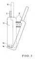
- the cellular terminal 11 is separated/fitted from/on the satellite unit 12. As shown in Fig. 3, the cellular terminal 11 and satellite unit 12 can be separated from each other. When communication via a satellite is not performed, the satellite unit 12 and cellular terminal 11 are separated from each other to disconnect the system connector 14a of the satellite unit 12 from the system connector 14b of the cellular terminal 11. In this case, the cellular terminal 11 can be used alone.
- the satellite unit 12 When communication via a satellite is performed, they cannot be used in a separated state. If they are separated from each other, the satellite unit 12 must be fitted on the cellular terminal 11.
- speech or data input from the cellular terminal 11 is transmitted to the satellite unit 12 via the system connector 14b and system connector 14a under the control of the cellular terminal 11. Finally, the speech or data is transmitted as a speech or data signal from the satellite antenna 13.
- the above procedure is reversed.
- the speech or data signal received by the satellite antenna 13 is sent to the satellite unit 12. This signal is then output as speech or data from the cellular terminal 11 via the system connector 14a and system connector 14b.
- the margin of the overall system with respect to radio wave transmission attenuation is smaller than that of a cellular.
- the indoor quality of transmission/reception via a satellite is much poorer than that with a cellular.
- a satellite communication terminal is required to perform transmission/reception in an outdoor place where a satellite can be directly seen or a similar environment, e.g., a place near a window, where radio wave transmission troubles are minimum between the satellite and the terminal.
- a special antenna may be provided for the cellular terminal separation type satellite communication portable terminal. This special antenna may be placed in a place near a window inside a building, vehicle, train, ship, or airplane, and signals transmitted via a satellite may be received inside via the special antenna.
- the above cellular terminal separation type satellite communication portable terminal already has the satellite antenna 13 as shown in Figs. 1 to 3, and hence two types of antenna, i.e., indoor and outdoor antennas, are used, resulting in an increase in cost.
- the first installation system for a cellular terminal separation type satellite communication portable terminal constituted by a ground cellular terminal capable of stand-alone communication and a satellite communication portable terminal which accommodates the ground cellular terminal, is electrically connected to the ground cellular terminal via predetermined connectors, and can communicate with a satellite under the control of the ground cellular terminal, comprising a fixing unit which is fixed to a place where radio wave transmission troubles are small and on which the separated satellite communication portable terminal is installed, and a connection unit which serves as an extension between the predetermined connectors and electrically connects the separated satellite communication portable terminal to the other separated ground cellular terminal so as to perform communication via a satellite.
- the second installation system for a cellular terminal separation type satellite communication portable terminal constituted by a ground cellular terminal capable of stand-alone communication and a satellite communication portable terminal which can be separated/fitted from/on the ground cellular terminal, comprising a fixing unit which is fixed to a fixed object in a place where radio wave transmission troubles are small and holds the separated satellite communication portable terminal, and means for electrically connecting the separated satellite communication portable terminal to the other separated ground cellular terminal.
- the third installation system for a cellular terminal separation type satellite communication portable terminal constituted by a ground cellular terminal capable of stand-alone communication and a satellite communication portable terminal which can be separated/fitted from/on the ground cellular terminal, comprising a fixing unit which is fixed to a fixed object in a place where radio wave transmission troubles are small and on which the separated satellite communication portable terminal is installed, and means for electrically connecting the separated satellite communication portable terminal to the other separated ground cellular terminal.
- the first installation method for a cellular terminal separation type satellite communication portable terminal constituted by a ground cellular terminal capable of stand-alone communication and a satellite communication portable terminal which accommodates the ground cellular terminal, is electrically connected to the ground cellular terminal via predetermined connectors, and can communicate with a satellite under the control of the ground cellular terminal, comprising the step of installing the separated satellite communication portable terminal in a place where radio wave transmission troubles are small, and the step of providing an extension between the predetermined connectors and electrically connecting the separated satellite communication portable terminal to the other separated ground cellular terminal so as to perform communication via a satellite.
- the second.installation method for a cellular terminal separation type satellite communication portable terminal constituted by a ground cellular terminal capable of stand-alone communication and a satellite communication portable terminal which can be separated/fitted from/on the ground cellular terminal, comprising the step of installing the separated satellite communication portable terminal in a place where radio wave transmission troubles are small, and the step of electrically connecting the separated satellite communication portable terminal to the other separated ground cellular terminal.
- the third installation method for a cellular terminal separation type satellite communication portable terminal constituted by a ground cellular terminal capable of stand-alone communication and a satellite communication portable terminal which can be separated/fitted from/on the ground cellular terminal, comprising the step of fixing the separated satellite communication portable terminal to a window glass, and the step of electrically connecting the separated satellite communication portable terminal to the other separated ground cellular terminal.
- the first method of using a cellular terminal separation type satellite communication portable terminal constituted by a ground cellular terminal capable of stand-alone communication and a satellite communication portable terminal which can be separated/fitted from/on the ground cellular terminal comprising the step of installing or holding the separated satellite communication portable terminal in a place where radio wave transmission troubles are small, and the step of electrically connecting the separated satellite communication portable terminal to the other separated ground cellular terminal.
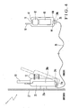
- Fig. 4 is a view showing the schematic arrangement of an installation system for a cellular terminal separation type satellite communication portable terminal according to the present invention.
- the cellular terminal separation type satellite communication portable terminal is of a type that allows a cellular terminal 11 capable of stand-alone communication to be separated from a satellite unit 12 in which the cellular terminal 11 is fitted/housed.
- the cellular terminal 11 and satellite unit 12 of the cellular terminal separation type satellite communication portable terminal are separated from each other, as shown in Fig. 4. In this state, communication is performed under the control of the cellular terminal 11. This makes it possible to make the cellular terminal separation type satellite communication portable terminal free from its unique problem, i.e., the restriction due to radio wave transmission troubles.
- the installation system for the cellular terminal separation type satellite communication portable terminal includes a fixing unit 25.
- the fixing unit 25 has a fixing portion 26a and fitting portion 26b.
- the fixing portion 26a of the fixing unit 25 is fixed at a portion near a window glass inside a building or of a moving object such as a vehicle, an airplane including a light airplane, a ship including a boat, or a train.
- a relatively good radio wave transmission condition is ensured at a window glass 27.
- the end face of the fixing portion 26a is formed by a suction cup, double-sided adhesive tape, or the like, and the fixing portion 26a is made to adhere to the window glass 27 by suction or fixed thereto with an adhesive in a simple manner.
- the satellite unit 12 is separated from the cellular terminal separation type satellite communication portable terminal.
- the satellite unit 12 then serves as a satellite communication portable terminal and fitted on the fitting portion 26b of the fixing unit 25 in place of the cellular terminal 11.
- the fixing unit 25 has a system connector 24a.
- the system connector 24a is directly connected to a system connector 14b of the satellite unit 12 when the satellite unit 12 is fitted on the fixing unit 25.
- a cable extension 28 is attached to the fixing unit 25.
- the cable extension 28 is connected to the system connector 24a.
- the other end portion of the cable extension 28 has a cable connector 29.
- the cable connector 29 has a system connector 24b.
- the system connector 24b is directly connected to the system connector 14b of the cellular terminal 11.
- the satellite unit 12 is fixed at a position where satellite radio wave reception condition is good.
- This makes it possible to move the cellular terminal 11 and perform communication via a satellite within the length of the cable extension 28.
- the user need not move to the outdoors or a window, together with the cellular terminal separation type satellite communication portable terminal. This increases the degree of freedom in indoor communication.
- the cellular terminal 11 is a terminal based on the cdmaOne system, which is the digital portable telephone system standardized in the U.S.A., Japan, and the like, the AMPS system, which is the analog portable telephone system standardized in the U.S.A., the GSM system, which is the digital portable telephone system standardized in Europe, or the PDC system, which is the digital portable telephone system standardized in Japan.
- the system connector 24a incorporated in the fixing unit 25 basically has the same function as that of the system connector 14b of the cellular terminal 11.
- system connector 24b incorporated in the cable connector 29 attached to the cable extension 28 has the same function as that of a system connector 14a incorporated in the satellite unit 12.
- speech or data from the cellular terminal 11 propagates through the cable extension 28 via the system connector 14b, system connector 24b, and cable connector 29, and is transmitted to the satellite unit 12 via the system connector 24a in the fixing unit 25 and the system connector 14a. Finally, the speech or data is transmitted as a speech or data signal from a satellite antenna 13.
- the speech or data signal received by the satellite antenna 13 is sent to the satellite unit 12 and propagates through the cable extension 28 via the system connector 14a and the system connector 24a in the fixing unit 25. This signal is further output as speech or data from the cellular terminal 11 via the cable connector 29, system connector 24b, and system connector 14b.
- the satellite unit 12 is of a fitting type, and hence can always be attached/detached.
- the user When, for example, the user is to go out, he/she detaches the satellite unit 12 from the fixing unit 25 and disconnects the cable connector 29 of the cellular terminal 11. Then, the cellular terminal 11 is fitted in the satellite unit 12 to allow the user to carry the satellite unit 12, as shown in Fig. 2.
- the cellular terminal 11 and satellite unit 12 are separated from each other to allow the user to use them in communication without the mediacy of a satellite or communication via a satellite inside buildings, vehicles, and the like.
- the fixing unit 25 since the fixing unit 25 has a cable connection point used for supply of power from the cellular terminal 11 or an external source, there is no need to perform cumbersome cable connection in attaching/detaching the satellite unit 12. This makes it easy to use the cellular terminal separation type satellite communication portable terminal.
- the cellular terminal 11 includes, for example, an RF unit 101 for performing radio signal processing, a CPU (Central Processing Unit) 102 for controlling the cellular terminal itself and controlling the satellite unit 12 to communicates with a satellite, and a memory 103 storing at least control programs for controlling the function of the cellular terminal and data.
- RF unit 101 for performing radio signal processing
- CPU Central Processing Unit
- the cellular terminal itself for controlling the cellular terminal itself and controlling the satellite unit 12 to communicates with a satellite
- a memory 103 storing at least control programs for controlling the function of the cellular terminal and data.
- the satellite unit 12 includes an RF section 104 for performing radio signal processing, a CPU 105 for controlling transmission/reception via a satellite, and a memory 106 which stores at least control programs for controlling the function of the satellite unit and data.
- the cellular terminal 11 and satellite unit 12 respectively have batteries.
- Control signals, audio signals, and charging currents are input/output between the cellular terminal 11 and the satellite unit 12.
- image signals and data signals can also be transmitted/received between the cellular terminal 11 and the satellite unit 12, as needed.
- the fitting portion 26b of the fixing unit 25 has the same shape as that of the portion of the cellular terminal 11 which is fitted on the fitting portion 26b.
- the satellite unit 12 is fitted on the fitting portion 26b.
- the fixing portion 26a is formed on the opposite side to the fitting portion 26b. As described above, the fixing portion 26a is made to adhere to the window glass 27 by suction or bonded thereto with an adhesive by using a suction cup, double-sided adhesive tape, or the like, and supports the weight of the satellite unit 12 and the like.
- the area of the fixing portion 26a fixed to the window glass 27 is determined by the weight of the satellite unit 12 and the like and suction force or adhesive force.
- a lock hole 26c is formed in the fitting portion 26b on the opposite side to the system connector 24a in the fixing unit 25.
- the lock hole 26c locks the pawl portion (not shown) of the satellite unit 12 to prevent the satellite unit 12 from being unfastened from the fitting portion 26b.
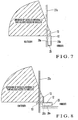
- Fig. 7 is a view showing a case where the satellite unit 12 and fixing unit 25 are installed inside a building.
- the fixing unit 25 is fixed to a window glass 27a inside the building or a portion around the window glass 27a, at which a relatively good radio wave transmission condition is ensured, with the fixing portion 26a of the fixing unit 25, and the satellite unit 12 is fitted on the fitting portion 26b of the fixing unit 25.
- the fixing unit 25 on which the satellite unit 12 is fitted can be easily detached from the window glass 27a when the window glass 27a is to be opened/closed. No trouble therefore arises when the window glass 27a is opened/closed.
- the satellite unit 12 and fixing unit 25 By attaching the satellite unit 12 and fixing unit 25 at a position near the lowermost portion of the window glass 27a, a wider coverage that allows access to the satellite can be ensured for the satellite antenna 13.
- the installation direction of the satellite antenna 13 of the satellite unit 12 must always be kept constant.
- the satellite antenna 13 can always be kept in a predetermined direction by attaching the satellite unit 12 to the fixing unit 25.
- Fig. 8 shows a modification of the arrangement in Fig. 7. If a flat portion such as a desk or table exists near the window glass 27a, the fixing portion 26a of the fixing unit 25 may be fixed on the flat portion. In this case, the satellite antenna 13 of the satellite unit 12 fitted on the fitting portion 26b of the fixing unit 25 is set vertical. This operation can be done if the antenna is designed to be pivotal vertically or horizontally.
- Fig. 9 is a view showing a modification of the arrangement in Fig. 7, in which the satellite unit 12 and fixing unit 25 are installed outdoors. As shown in Fig. 9, the fixing portion 26a of the fixing unit 25 may be fixed to an outer wall of a building.
- this system can also be applied to a telephone conference system.
- Fig. 10 is a view showing a case where the satellite unit 12 and fixing unit 25 are installed inside a vehicle.
- the fixing unit 25 is fixed to a window glass 27b of the vehicle or a door 32 near the window glass 27b, at which a relatively good radio wave transmission condition is ensured, with the fixing portion 26a of the fixing unit 25, and the satellite unit 12 is fitted on the fitting portion 26b of the fixing unit 25.
- the fixing unit 25 on which the satellite unit 12 is fitted can be easily detached from the window glass 27b as in the case of indoor use, no problem arises when the window glass 27b and door 32 are opened/closed.
- the satellite unit 12 and fixing unit 25 are attached to a portion near the lowermost portion of the window glass 27b, a wide coverage that allows access to the satellite can be ensured for the satellite antenna 13, as shown in Fig. 10, even in a vehicle as in the case of indoor installation.
- the use can communicate with the satellite by selecting the fixing unit 25 mounted on the window glass 27b located outside the shadow.
- Fig. 11 is a view showing a modification of the arrangement in Fig. 10, in which the satellite unit 12 and fixing unit 25 are installed on a front portion of a vehicle.
- the fixing portion 26a of the fixing unit 25 may be fixed to a flat portion near a front glass 27c of the vehicle.
- the satellite antenna 13 of the satellite unit 12 fitted on the fitting portion 26b of the fixing unit 25 pivots to become vertical.
- Fig. 12 is a view showing a modification of the arrangement in Fig. 10, in which the satellite unit 12 and fixing unit 25 are installed on a rear portion of the vehicle.
- the fixing portion 26a of the fixing unit 25 my be fixed to a flat portion near a rear glass 27d of the vehicle.
- the satellite antenna 13 of the satellite unit 12 fitted on the fitting portion 26b of the fixing unit 25 is set vertical.
- Fig. 13 is a view showing a modification of the arrangement in Fig. 10, in which the satellite unit 12 and fixing unit 25 are installed at a sun roof portion of the vehicle.
- a plate 34 exhibiting a radio wave transmission attenuation may be mounted on a glass 27e of a sun roof or moon roof 33a to be vertical, and the fixing portion 26a of the fixing unit 25 may be fixed to the plate 34.
- Fig. 14 is a view showing a modification of the arrangement in Fig. 13, in which the satellite unit 12 and fixing unit 25 are installed at a sun roof portion of the vehicle.
- the fixing portion 26a of the fixing unit 25 may be fixed to the glass 27e of the sun roof or moon roof 33a.
- the satellite antenna 13 of the satellite unit 12 fitted on the fitting portion 26b of the fixing unit 25 is set vertical.
- the vertical satellite antenna 13 protrudes outside from an opening portion 35 of the open sun roof 33a.
- Fig. 15 shows a modification of the fixing unit in Fig. 6.
- the fixing portion 26a of the fixing unit 25 is designed in the form of a drink holder to be hooked in a gap in a window glass housing portion of a vehicle door.
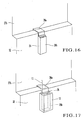
- Fig. 16 is a view showing how the fixing unit 25 is attached to a vehicle window. As shown in Fig. 16, the fixing unit 25 can be hooked and fixed in a gap of the window glass housing portion of the window glass 27b of the door 32 at the driver's seat, front passenger seat, or rear passenger seat of the vehicle.
- Fig. 17 is a view showing how the satellite unit 12 is fitted on the fixing unit 25 in Fig. 16. As shown in Fig. 17, the satellite unit 12 is fitted on the fitting portion 26b of the fixing unit 25. This eliminates the necessity to detach the fixing unit 25 when the window glass 27b is opened/closed.
- Fig. 18 is a view showing an example of how the fixing units 25 are arranged at a plurality of positions in the vehicle. As shown in Fig. 18, the fixing units 25 can be fixed at the driver's seat, front passenger seat, and the window glass housing portions of the window glasses 27b at the rear passenger seats. The fixing units 25 can also be fixed near the front glass 27c and rear glass 27d.
- the fixing units 25 can be fixed near window glasses 27e of the sun roof and moon roof 33a.
- Fig. 19 is a sectional view showing a modification of the fixing unit 25 in Fig. 6.
- a buffer circuit 51 is provided for the fixing unit 25 as needed.
- the buffer circuit 51 is connected between the system connector 24a and the cable extension 28 (Fig. 4) to correct a signal change due to a cable loss.
- Fig. 20 is a sectional view showing a modification of the fixing unit 25 in Fig. 6.
- a take-up/housing mechanism 52 is provided for the fixing unit 25.
- the take-up/housing mechanism 52 takes up the cable extension 28 and houses it.
- the take-up/housing mechanism 52 takes up the cable extension 28 of the fixing unit 25, which is not used, and houses it.
- Fig. 21 is a sectional view showing a modification of the fixing unit 25 in Fig. 20.
- a charging unit 53 is provided for the fixing unit 25.
- the charging unit 53 charges the batteries of the satellite unit 12 and cellular terminal 11.
- the charging unit 53 charges the cellular terminal 11 via the cable extension 28.
- FIG. 22 is a view showing a modification of the arrangement in Fig. 4, in which the cellular terminal 11 communicates with the satellite unit by radio. As shown in Fig. 22, as compared with the arrangement in Fig. 4, the cellular terminal 11 is connected to the satellite unit 12 by radio. The cellular terminal 11 communicates with a satellite by radio via the satellite unit 12.
- the cable extension 28 is not required, and hence need not be routed, thereby further increasing the degree of freedom of the movement of the user.
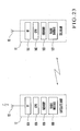
- Fig. 23 is a block diagram showing the schematic circuit arrangement of the cellular terminal 11 and satellite unit 12.
- the cellular terminal 11 and satellite unit 12 further include radio modules 107 and 108.
- the radio modules 107 and 108 for example, modules based on a radio scheme such as Bluetooth for short-distance communication of data and speech are used. The use of this scheme facilitates radio connection.
- the cellular terminal 11 In communicating with a satellite, the cellular terminal 11 transmits/receives control signals, audio signals, image signals, data signals, and the like to/from the satellite unit 12 by radio via the radio modules 107 and 108.
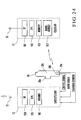
- Fig. 24 is a view showing a modification of the arrangement in Fig. 23.
- the radio module 108 of the satellite unit 12 is mounted in the fixing unit 25.
- the cellular terminal 11 transmits/receives control signals, audio signals, image signals, data signals, and the like via the radio module 107, the radio module 108 of the fixing unit 25, and the system connectors 24a and 14a. This reduces the load on the satellite unit 12.
- Fig. 25 is a side sectional view showing a fixing method using a double-sided suction cup type fixing unit (fixing member).
- one suction cup 60a of a double-sided suction cup type fixing unit (fixing member) 60 is fixed to the window glass 27 by suction.
- the other suction cup 60b sucks the inside outer surface of the satellite unit 12 to hold the satellite unit 12.
- Fig. 26 shows a case where the suction cup 60b of the double-sided suction cup type fixing unit (fixing member) sucks the outside outer surface of the satellite unit 12 to hold the satellite unit 12.
- the fixing method using the double-sided suction cup type fixing unit (fixing member) in Figs. 25 and 26 is very simple as well as allowing the fixing unit itself to have a very simple, low-cost structure.
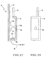
- Fig. 27 is a side sectional view showing a fixing method using a suction cup/projection type fixing unit (fixing member).
- a suction cup 61a of a suction cup/projection type fixing unit (fixing member) 61 is fixed to the window glass 27 by suction.
- a fitting hole 12a (Fig. 28) formed in the satellite unit 12 is fitted on a projection 61b of the suction cup/projection type fixing unit (fixing member) 61 and the satellite unit 12 is pushed downward, the projection 61b is sufficiently fitted in the fitting hole 12a, thereby fixing/holding the satellite unit 12.
- the fixing method using this suction cup/projection type fixing unit is a simple, low-cost fixing method like that shown in Figs. 25 and 26.
- the satellite communication portable terminal is set on the fixing unit fixed to a place where radio wave registration troubles are small, and the ground cellular terminal separated from the satellite communication portable terminal can communicate with the satellite communication portable terminal. Therefore, in performing communication via a satellite, the user need not move to the outdoors, a window, or the like, together with the terminal as in the prior art. This makes it possible increase the degree of freedom in communication in buildings and vehicles.
Landscapes
- Engineering & Computer Science (AREA)
- Computer Networks & Wireless Communication (AREA)
- Signal Processing (AREA)
- Physics & Mathematics (AREA)
- Astronomy & Astrophysics (AREA)
- Aviation & Aerospace Engineering (AREA)
- General Physics & Mathematics (AREA)
- Radio Relay Systems (AREA)
- Telephone Set Structure (AREA)
- Mobile Radio Communication Systems (AREA)
- Telephone Function (AREA)
Applications Claiming Priority (2)
| Application Number | Priority Date | Filing Date | Title |
|---|---|---|---|
| JP2000083203A JP3536972B2 (ja) | 2000-03-21 | 2000-03-21 | セルラー端末分離型衛星通信携帯端末の設置システム及び方法 |
| EP01912494A EP1267583A4 (de) | 2000-03-21 | 2001-03-19 | Installationssystem und verfahren für ein tragba-res satellitenkommunikationsendgerät des zellularen endgerätetrennungstyps |
Related Parent Applications (1)
| Application Number | Title | Priority Date | Filing Date |
|---|---|---|---|
| EP01912494A Division EP1267583A4 (de) | 2000-03-21 | 2001-03-19 | Installationssystem und verfahren für ein tragba-res satellitenkommunikationsendgerät des zellularen endgerätetrennungstyps |
Publications (1)
| Publication Number | Publication Date |
|---|---|
| EP1631097A2 true EP1631097A2 (de) | 2006-03-01 |
Family
ID=18599882
Family Applications (2)
| Application Number | Title | Priority Date | Filing Date |
|---|---|---|---|
| EP01912494A Withdrawn EP1267583A4 (de) | 2000-03-21 | 2001-03-19 | Installationssystem und verfahren für ein tragba-res satellitenkommunikationsendgerät des zellularen endgerätetrennungstyps |
| EP05025713A Withdrawn EP1631097A2 (de) | 2000-03-21 | 2001-03-19 | Installationssystem und Verfahren für ein tragbares Satellitenkommunikationsendgerät des zellularen Endgerätetrennungstyps |
Family Applications Before (1)
| Application Number | Title | Priority Date | Filing Date |
|---|---|---|---|
| EP01912494A Withdrawn EP1267583A4 (de) | 2000-03-21 | 2001-03-19 | Installationssystem und verfahren für ein tragba-res satellitenkommunikationsendgerät des zellularen endgerätetrennungstyps |
Country Status (6)
| Country | Link |
|---|---|
| US (1) | US20030171097A1 (de) |
| EP (2) | EP1267583A4 (de) |
| JP (1) | JP3536972B2 (de) |
| AU (1) | AU2001241200A1 (de) |
| TW (1) | TW516331B (de) |
| WO (1) | WO2001072066A1 (de) |
Families Citing this family (13)
| Publication number | Priority date | Publication date | Assignee | Title |
|---|---|---|---|---|
| EP1349289A1 (de) * | 2002-03-27 | 2003-10-01 | Agilent Technologies, Inc. (a Delaware corporation) | Kostengünstige S-UMTS Erweiterung für ein T-UMTS endgerät |
| JP2006166002A (ja) * | 2004-12-07 | 2006-06-22 | Itc Japan Kk | 航空機等において携帯電話機を使用して通信を行う方法及び携帯電話機並びにプログラム |
| KR100673406B1 (ko) | 2005-01-26 | 2007-01-24 | 아태위성산업 주식회사 | 지상 휴대전화기에 탑재되는 위성 통신 장치 및 방법 |
| US20110136428A1 (en) * | 2009-12-07 | 2011-06-09 | Douglas Ritter | Enhanced communication device having terrestrial and satellite communication capabilities |
| US8676122B2 (en) * | 2010-08-27 | 2014-03-18 | Gregory H. Piesinger | Secure satellite modem for personal digital assistant method and apparatus |
| KR101402885B1 (ko) * | 2012-04-13 | 2014-06-02 | 에이피위성통신주식회사 | 위성 통신을 위한 위성 단말기와 모바일 단말기의 결합 시스템 및 방법 |
| EP2874327B1 (de) * | 2012-06-20 | 2021-05-19 | Mitsubishi Electric Corporation | Aussenbatterie und satellitenkommunikationsendgerät |
| US20140128132A1 (en) * | 2012-10-12 | 2014-05-08 | James L. Cox, III | Case with interchangeable back plates |
| US9319087B1 (en) * | 2012-10-12 | 2016-04-19 | James L. Cox, III | Protective case for coupling communication devices to a mobile device |
| KR101446520B1 (ko) * | 2013-03-25 | 2014-10-06 | 에이피위성통신주식회사 | 휴대용 위성통신장치 |
| EP2938158B1 (de) * | 2014-04-24 | 2019-07-24 | Deutsche Telekom AG | Anordnung zur Bereitstellung von Breitband-Zugängen für ein Weitverkehrsnetz |
| US10251045B2 (en) * | 2015-10-05 | 2019-04-02 | Mcleanics Technology Corporation | Satlink convertor/communicator |
| CN111082854A (zh) * | 2018-10-18 | 2020-04-28 | 南京眼湖信息科技有限公司 | 天通小猫便携式卫星终端 |
Family Cites Families (26)
| Publication number | Priority date | Publication date | Assignee | Title |
|---|---|---|---|---|
| JP2698653B2 (ja) * | 1989-04-09 | 1998-01-19 | 松下電工株式会社 | 拡声通話式のインターホンシステム |
| JP2993087B2 (ja) * | 1990-09-19 | 1999-12-20 | 日本電気株式会社 | 携帯電話機 |
| JPH0580906U (ja) * | 1992-03-28 | 1993-11-02 | 昭 野口 | 吸盤式携帯電話機車載ホルダー |
| JPH0594009U (ja) * | 1992-05-28 | 1993-12-21 | 株式会社ホンダアクセス | 自動車用電話装置 |
| JPH0774693A (ja) * | 1993-09-02 | 1995-03-17 | Nippon Telegr & Teleph Corp <Ntt> | 携帯電話機 |
| US5828951A (en) * | 1994-08-29 | 1998-10-27 | Nec Corporation | Mobile satellite terminal equipment |
| WO1996008878A1 (en) * | 1994-09-14 | 1996-03-21 | Ericsson Inc. | Satellite communications adapter for cellular handset |
| NO960329L (no) * | 1995-01-27 | 1996-07-29 | Nec Corp | Mobil satelitt-komunikasjonsterminal |
| SE504065C2 (sv) * | 1995-03-15 | 1996-10-28 | Volvo Ab | Radiomottagare för användning i fordon |
| GB9525110D0 (en) * | 1995-12-08 | 1996-02-07 | Northern Telecom Ltd | An antenna assembly |
| JPH09261166A (ja) * | 1996-03-25 | 1997-10-03 | Nippon Eisei Denwa Kk | 移動体通信端末システム |
| JPH09261165A (ja) * | 1996-03-25 | 1997-10-03 | Nippon Eisei Denwa Kk | 移動体通信端末システム |
| JPH1079978A (ja) * | 1996-09-04 | 1998-03-24 | Tac:Kk | 無線通信機器の呼出装置 |
| US6002937A (en) * | 1996-10-31 | 1999-12-14 | Motorola, Inc. | Method of and apparatus for communicating information signals |
| AR011161A1 (es) * | 1997-02-28 | 2000-08-02 | Kyocera Corp | Unidad de comunicacion satelital movil de modalidad dual |
| US5937332A (en) * | 1997-03-21 | 1999-08-10 | Ericsson, Inc. | Satellite telecommunications repeaters and retransmission methods |
| JPH10276251A (ja) * | 1997-03-27 | 1998-10-13 | Car Mate Mfg Co Ltd | 通信機器保持装置 |
| JP3033707B2 (ja) * | 1997-04-02 | 2000-04-17 | 埼玉日本電気株式会社 | 携帯電話機の車載ホルダ構造 |
| JPH10336311A (ja) * | 1997-05-30 | 1998-12-18 | Calsonic Corp | ハンズフリー電話システム |
| US5901367A (en) * | 1997-06-10 | 1999-05-04 | Hughes Electronics Corporation | Low insertion loss connection of an antenna to a mobile radio |
| JPH1127351A (ja) * | 1997-07-01 | 1999-01-29 | Ii & S:Kk | 携帯無線機用ホルダー |
| JP3488819B2 (ja) * | 1997-12-24 | 2004-01-19 | 京セラ株式会社 | 充電器 |
| JPH11215022A (ja) * | 1998-01-27 | 1999-08-06 | Matsushita Electric Works Ltd | 移動体通信端末 |
| JPH11243362A (ja) * | 1998-12-25 | 1999-09-07 | Matsushita Electric Ind Co Ltd | 無線電話装置,無線電話中継装置および無線電話システム |
| US6914897B1 (en) * | 1999-09-27 | 2005-07-05 | 3 Com Corporation | System and method for accessing radio programs using a data network telephone in a network based telecommunication system |
| US6341218B1 (en) * | 1999-12-06 | 2002-01-22 | Cellport Systems, Inc. | Supporting and connecting a portable phone |
-
2000
- 2000-03-21 JP JP2000083203A patent/JP3536972B2/ja not_active Expired - Fee Related
-
2001
- 2001-03-15 TW TW090106039A patent/TW516331B/zh not_active IP Right Cessation
- 2001-03-19 US US10/239,076 patent/US20030171097A1/en not_active Abandoned
- 2001-03-19 AU AU2001241200A patent/AU2001241200A1/en not_active Abandoned
- 2001-03-19 EP EP01912494A patent/EP1267583A4/de not_active Withdrawn
- 2001-03-19 WO PCT/JP2001/002176 patent/WO2001072066A1/ja not_active Ceased
- 2001-03-19 EP EP05025713A patent/EP1631097A2/de not_active Withdrawn
Also Published As
| Publication number | Publication date |
|---|---|
| EP1267583A1 (de) | 2002-12-18 |
| EP1267583A4 (de) | 2004-04-07 |
| TW516331B (en) | 2003-01-01 |
| AU2001241200A1 (en) | 2001-10-03 |
| JP2001268652A (ja) | 2001-09-28 |
| US20030171097A1 (en) | 2003-09-11 |
| WO2001072066A1 (en) | 2001-09-27 |
| JP3536972B2 (ja) | 2004-06-14 |
Similar Documents
| Publication | Publication Date | Title |
|---|---|---|
| EP1631097A2 (de) | Installationssystem und Verfahren für ein tragbares Satellitenkommunikationsendgerät des zellularen Endgerätetrennungstyps | |
| US6021317A (en) | Dual antenna radiotelephone systems including an antenna-management matrix switch and associated methods of operation | |
| US8473018B2 (en) | Mobile device cradle having an integrated antenna or amplifier | |
| EP1428330B1 (de) | Telefonsteuerung im einem flugdeck | |
| JP2503906B2 (ja) | 携帯無線機 | |
| JPH08509331A (ja) | 無線周波信号を使用したデータ送信の方法及び装置 | |
| JPH01220919A (ja) | 無線電話装置 | |
| JPH11261468A (ja) | 航空機において無線通信手段の使用を可能にする装置 | |
| EP1384626A1 (de) | Spiegelvorrichtung mit eingebautem zwischenverstärker zur drahtlosen kommunikation | |
| US20020013138A1 (en) | Radio receiver | |
| JP3450219B2 (ja) | 携帯型移動無線電話装置 | |
| US20040104855A1 (en) | Radio communication apparatus | |
| EP2517449B1 (de) | System zum empfang von satellitendaten | |
| US7079074B2 (en) | Receiver for receiving satellite-based navigation signals, and navigation system | |
| JPH0722264B2 (ja) | 自動車電話用移動機 | |
| JPH06104826A (ja) | 無線電話装置 | |
| GB2314483A (en) | Mobile phone with additional plug-in communication module | |
| US20060128450A1 (en) | Portable terminal and portable terminal communication method | |
| JPH0714745U (ja) | 自動車電話システム | |
| FI84000C (fi) | Antennsystem foer fordon. | |
| KR200204941Y1 (ko) | Gps 수신장치를 내장한 휴대폰 핸드프리 킷트 | |
| US20070082665A1 (en) | Handsfree device for a mobile telephone | |
| KR200209079Y1 (ko) | 주파수 공용 무선전화기의 안테나 연결구조 | |
| JPH09261166A (ja) | 移動体通信端末システム | |
| EP1126634A2 (de) | Verbessertes Satellitendatenendgerät |
Legal Events
| Date | Code | Title | Description |
|---|---|---|---|
| PUAI | Public reference made under article 153(3) epc to a published international application that has entered the european phase |
Free format text: ORIGINAL CODE: 0009012 |
|
| AC | Divisional application: reference to earlier application |
Ref document number: 1267583 Country of ref document: EP Kind code of ref document: P |
|
| AK | Designated contracting states |
Kind code of ref document: A2 Designated state(s): AT BE CH CY DE DK ES FI FR GB GR IE IT LI LU MC NL PT SE TR |
|
| AX | Request for extension of the european patent |
Extension state: AL LT LV MK RO SI |
|
| STAA | Information on the status of an ep patent application or granted ep patent |
Free format text: STATUS: THE APPLICATION HAS BEEN WITHDRAWN |
|
| 18W | Application withdrawn |
Effective date: 20090723 |