EP1629265B1 - Automatische detektion wenigstens eines in einem flüssigen betriebsstoff enthaltenen fluoreszierenden und/oder lichtabsorbierenden indikators während des einfüllvorgangs des betriebsstoffs in eine maschine - Google Patents
Automatische detektion wenigstens eines in einem flüssigen betriebsstoff enthaltenen fluoreszierenden und/oder lichtabsorbierenden indikators während des einfüllvorgangs des betriebsstoffs in eine maschine Download PDFInfo
- Publication number
- EP1629265B1 EP1629265B1 EP04734681A EP04734681A EP1629265B1 EP 1629265 B1 EP1629265 B1 EP 1629265B1 EP 04734681 A EP04734681 A EP 04734681A EP 04734681 A EP04734681 A EP 04734681A EP 1629265 B1 EP1629265 B1 EP 1629265B1
- Authority
- EP
- European Patent Office
- Prior art keywords
- light
- operating material
- engine
- receiving device
- measuring
- Prior art date
- Legal status (The legal status is an assumption and is not a legal conclusion. Google has not performed a legal analysis and makes no representation as to the accuracy of the status listed.)
- Expired - Lifetime
Links
Images

Classifications
-
- G—PHYSICS
- G01—MEASURING; TESTING
- G01N—INVESTIGATING OR ANALYSING MATERIALS BY DETERMINING THEIR CHEMICAL OR PHYSICAL PROPERTIES
- G01N21/00—Investigating or analysing materials by the use of optical means, i.e. using sub-millimetre waves, infrared, visible or ultraviolet light
- G01N21/62—Systems in which the material investigated is excited whereby it emits light or causes a change in wavelength of the incident light
- G01N21/63—Systems in which the material investigated is excited whereby it emits light or causes a change in wavelength of the incident light optically excited
- G01N21/64—Fluorescence; Phosphorescence
- G01N21/6428—Measuring fluorescence of fluorescent products of reactions or of fluorochrome labelled reactive substances, e.g. measuring quenching effects, using measuring "optrodes"
- G01N2021/6439—Measuring fluorescence of fluorescent products of reactions or of fluorochrome labelled reactive substances, e.g. measuring quenching effects, using measuring "optrodes" with indicators, stains, dyes, tags, labels, marks
-
- G—PHYSICS
- G01—MEASURING; TESTING
- G01N—INVESTIGATING OR ANALYSING MATERIALS BY DETERMINING THEIR CHEMICAL OR PHYSICAL PROPERTIES
- G01N21/00—Investigating or analysing materials by the use of optical means, i.e. using sub-millimetre waves, infrared, visible or ultraviolet light
- G01N21/17—Systems in which incident light is modified in accordance with the properties of the material investigated
- G01N21/25—Colour; Spectral properties, i.e. comparison of effect of material on the light at two or more different wavelengths or wavelength bands
- G01N21/31—Investigating relative effect of material at wavelengths characteristic of specific elements or molecules, e.g. atomic absorption spectrometry
Definitions
- the present invention relates to a method for automatically detecting at least one fluorescent and / or light-absorbing indicator contained in a liquid fuel during the filling operation of the fuel into a machine, and to a machine having an apparatus integrated therein for carrying out the method.
- Liquid operating materials for the purposes of the present application are lubricating oil, engine oil and hydraulic oil.
- the quality of a fuel is crucial for the determination of the fuel change interval.
- modern motor vehicles already have on-board computers which calculate or adapt the oil change intervals as a function of various operating parameters.
- the quality of the filled lubricating oil can not be automatically taken into account.
- US Pat. No. 6,274,381 B1 proposes using two or more visible dyes in a fuel whose absorption maxima are at different wavelengths. If a sample of such a labeled fuel is placed in a suitable laboratory instrument, the indicator can be determined. According to US Pat. No. 6,274,381 B1, a light source is used for this purpose and the absorption caused by the indicators is determined.
- US 5,958,780 discloses a measuring device for detecting at least one in a fuel-containing fluorescent and / or light-absorbing indicator with a measuring path formed by a transparent material, which is traversed by the fuel, at least one light source which radiates onto the measuring path, a light receiving device, to the light which passes through the fuel flowing through the measurement path and / or emanates from the indicator due to a fluorescence effect and which generates a corresponding measurement signal dependent on the intensity of the incident light, and an evaluation unit for evaluating the measurement signal.
- the measuring device is arranged on a line leading away from a storage tank, wherein it is not specified in more detail, which is located at the other end of the line.
- No. 5,225,679 discloses a measuring device arranged in a line leading from a storage tank to a motor vehicle for determining the properties of the fuel by means of infrared absorption spectroscopy.
- the object of the present invention is to enable an automatic detection of the identity of a fuel contained in a machine.
- a machine in particular an engine of a vehicle, having an integrated device for automatically detecting at least one fluorescent and / or light-absorbing indicator contained in a liquid operating substance, namely lubricating oil, engine oil or hydraulic oil, during the filling process of the operating material into the vehicle Machine, wherein the device is a filler pipe for the fuel through which the fuel to be filled enters the fuel supply of the machine, formed by a transparent material measuring path, which is at least partially filled or traversed when filling the fuel into the filler pipe with the operating material, at least a light source which radiates onto the measuring path, a light receiving device, which is hit by light which passes through the operating medium when flowing through the measuring path and / or by the indicator due to a Fluorescence effect emanates, and at least one of the strength of the incident light on the light receiving device dependent measurement signal generated, and an evaluation unit, in which the at least one measurement signal of the light receiving device is evaluated comprises.
- a liquid operating substance namely lubricating oil, engine oil or hydraulic oil
- the design according to the invention makes it possible for the first time to automatically detect a liquid operating material, in particular its identity or quality, when it is filled into a machine.
- the invention has recognized that commonly used consumables have in their absorption spectrum areas with a significantly reduced absorption.
- it has been found that in the range of 500 to 1000 nm no or reduced absorption occurs, and therefore offer these areas especially for marking with indicators.
- 500 nm excitation of the fluorescence indicators is well possible because the exciting light is not or hardly absorbed by the fuel.
- the light emitted by the fluorescence indicator can be determined particularly well in the range above 500 nm, since the absorption of the working fluid does not or only slightly influences the measurement result.
- dyes in particular fluorescent dyes
- the apparatus has a measuring section formed by a transparent material which is at least partially filled or flowed through with the operating fluid when the operating fluid is introduced into the machine.
- the or the indicators and their concentration can be measured.
- the resulting measurement signal is then further processed by an evaluation unit. For example, it is possible to compare the measurement signals with data stored in advance in an evaluation matrix and in this way to obtain information about the filled-in substance in the machine. This information can then be further utilized automatically, for example, to calculate a fuel change interval adapted to the quality of the filled fuel.
- the light receiving device has at least two light sensors which have frequency ranges deviating from one another and in each case generate a measuring signal.
- a plurality of indicators can be measured by the device. If one also considers that different concentration thresholds of the indicators can be determined according to the invention, a large number of coding possibilities results.
- concentration thresholds of the indicators can be determined according to the invention, a large number of coding possibilities results.
- two indicators and four concentration levels there are already 16 coding possibilities. Using three dyes and four levels of concentration increases that number to 64 and increases to 256 encoding possibilities using four indicators.
- the light source and the light receiving device are aligned with the measuring path and arranged at an angle of 0 to 170 degrees around the measuring path.
- the light source and the light receiving device are arranged at an angle of 30 to 140, in particular 60 to 120 degrees.
- the filler pipe in the flow direction before the measuring section has a section opening into the measuring section with a cross-sectional reduction.
- This cross-sectional reduction is arranged in particular above the measuring section, wherein it is sufficient if only a partial flow of the filled fuel passes through the measuring section.
- the measuring section is designed as a measuring tube, which opens directly or indirectly in the fuel supply of the machine.
- a further improvement is achieved in that a plurality of light sources are provided which radiate in different frequency ranges, thereby facilitating the detection of different indicators.
- the signal resulting from the evaluation of the measurement signals can be further used in the machine.
- the identity or other information about the filled fuel can be automatically determined and automatically processed, for example, in the on-board computer.
- the start of the machine could be prevented or the operating range could be limited so that no damage to be feared.
- the fuel change interval is calculated or adjusted in dependence on the filled fuel.
- the at least one indicator is a fluorescent dye, which is excited by the light source in the measuring section to fluorescence radiation, wherein the fluorescent radiation forms at least part of the light collected by the light receiving device.
- the operating material contains at least two indicators acting in different frequency ranges and that the indicators, in particular their concentration, are detected by at least two sensors of the light receiving device that are sensitive in the different frequency ranges.
- the measurement signal or signals generated by the light receiving device correlate with the concentration of the at least one indicator in the operating substance.
- one of the indicators of the fuel forms a reference indicator, by means of which the light receiving device generates a reference signal. In this way, in particular the evaluation of the measurement signals can be facilitated.
- the evaluation unit evaluates the at least one measurement signal on the basis of the ratio of the strength of the at least one measurement signal to the strength of the reference signal. In this way, even under variable conditions, e.g. changing filling level of the measuring section with fuel, the concentrations of the indicators contained in the operating material are reliably determined. In this case, it is sufficient to determine the ratio of the indicators by putting the measurement signal (s) in relation to the reference signal.
- the evaluation is particularly simple if the reference indicator is always present in a constant concentration.
- the evaluation unit assigns a quality signal to the at least one measurement signal. This can be done, for example, by comparing the measurement signals determined concentration levels of the various indicators with a table or matrix of values are assigned in each of which combinations of the concentration levels of indicators certain qualities or other information about the fuel.
- the evaluation unit can be integrated, for example, in the on-board computer of a motor vehicle.
- FIG. 1 schematically shows a device for automatically detecting at least one liquid contained in a liquid Indicator displayed during the filling process of the fuel in a machine.
- the device has for filling the fuel to a filler pipe 1 for the fuel.
- each component that enables or facilitates the filling process of fuel into the machine should be considered a filler pipe, regardless of its cross-sectional shape or the ratio of diameter and length.
- the filler pipe may be formed in particular round or square.
- the elongate filler pipe 1 has a circular cross-section.
- the filler pipe of the device is designed and arranged such that filled fuel passes through the filler pipe 1 directly or indirectly into the fuel supply 12, for example, the oil pan of the machine.
- the device has a measuring section 2 formed by a light-transmissive material.
- a measuring section 2 formed by a light-transmissive material.
- this is formed by an existing example of clear plastic or glass pipe section.
- the measuring section 2 is at least partially filled or flowed through when filling the fuel into the filler pipe 1. It is sufficient if only part of the filled fuel flows through the measuring section 2 for measurement purposes.
- the device has a light source 3, which radiates onto the measuring section 2 and is directed onto it.
- the light emanating from the light source 3 may be a focused beam 4, which is focused in particular on the center of the measuring section 2.
- the device furthermore has a light receiving device 5. This is hit by light which passes through the fuel as it flows through the measuring section 2 and / or emits the fuel due to a fluorescence effect (light 14).
- the illustrated light receiving device 5 has two light sensors 6, 7. These have different frequency ranges.
- the maximum of the spectral sensitivity of the light sensors 6, 7 is different and adapted to the indicators used. In this way, the presence and / or the concentration of an indicator in the operating material can be determined by a respective light sensor 6,7.
- a single sensor may be sufficient.
- the light receiving device 5 generates by means of the light sensors 6, 7 in particular a plurality of measurement signals. Shown in FIG. 1 is a measuring signal 8 of the light sensor 6 and a measuring signal 9 of the light sensor 7. As sensors 6, 7 of the light receiving device 5, PIN diodes in particular can be used.
- the light receiving device 5 also has a beam splitter 11, is distributed by the incident light evenly to the light sensors 6,7.
- FIG. 1 also shows an evaluation unit 10 in which the at least one measurement signal 8, 9 of the light receiving device 5 is evaluated.
- the light source 3 and the light receiving device 5 are aligned with the measuring section 2 of the filling tube 1 of the machine and arranged at an angle ⁇ of 0 to 170 degrees around the measuring section 2 around.
- an angle ⁇ of 0 to 170 degrees around the measuring section 2 around an angle of 30 to 140 degrees, preferably 60 to 120 degrees particularly well proven. If the indicators and their concentration in the operating material are to be determined not by fluorescence measurement but by absorption measurement, the light receiving device 5 is placed directly opposite the light source 3, ie in particular at an angle ⁇ of 180 ° thereto.
- the filler pipe 1 has a section 15 with a cross-sectional reduction, which is arranged upstream of the measuring section 2 in the direction of flow. Due to the cross-sectional constriction, a complete filling of the measuring section with the operating material can be achieved.
- the light sources can be formed particularly simply by LEDs and / or laser diodes.
- the LED or laser diodes can have different wavelengths.
- the device shown in FIG. 1 is integrated into a machine, in particular an engine of a vehicle.
- one, preferably two or more different fluorescent dyes are added to the operating materials.
- a concentration in the range 10 -7 to 10 -9 moles is sufficient.
- higher concentrations in particular up to 10 -4 mol.
- Oil-soluble dyes from the group of coumarins, fluoresceins, rhodamines, oxazines and carbocyanines or their oil-soluble modifications can be used as fluorescent dyes. Due to the low concentration of indicators In the operating materials, the intended properties of the operating materials are not or only insignificantly influenced. The dye can not be seen by eye as it is added in very low concentrations.
- fluorescent dyes it is also possible to use non-fluorescent dyes, for example diazo dyes.
- oil-soluble dyes are used, in particular fluorescent dyes having emission maxima in the range from 500 nm to 1000 nm.
- the detection of the indicators used is carried out during the filling process by excitation by the light sources 3, for example LED or laser diodes, in different, matched to the dyes used wavelength ranges.
- the engine oils may be excited at, for example, 370, 490 and / or 570 to 590 nm.
- the light receiving device By the light receiving device then light is collected.
- fluorescent dyes light emitted by the indicator 14 due to the fluorescence effect is collected.
- non-fluorescent dyes the light passing through the fuel is used.
- the sensors 5, 6 of the light receiving device 5 each generate a measuring signal 8, 9, which reflect the intensity of the light 14 striking the light receiving device 5. Accordingly, the presence and the concentration of the indicators in the operating material can be determined by the evaluation unit 10 on the basis of the measurement signals 8, 9.
- a comparison is made with comparison values stored in a table.
- the identity of the filled fuel is determined and generates a quality signal. This makes it possible to automatically detect the identity of the filled fuel or other information about this and machine further processing the information thus obtained.
- the information about the filled fuel can be used to calculate oil change intervals.
- the operation of the machine can be prevented or the operating range can be restricted if a fuel with a lower than the recommended specification is filled.
- the evaluation is made possible by the fact that the measurement signals 8, 9 generated by the light receiving device 5 correlate with the concentration of the at least one indicator in the operating material.
- one of the indicators or dyes of the operating substance forms a reference indicator.
- the idea behind this is to provide the reference indicator either in an alternating or in an always constant concentration in the fuel. If, for example, the light sensor 6 detects the reference indicator, then the resulting measurement signal 8 forms the reference signal.
- the light sensor 7 detects a further indicator of the operating substance and generates a measuring signal 9 dependent on the concentration of this indicator in the operating fluid.
- the concentration of the indicator or the concentration ratio can always be reliably determined of the indicators. This can also be done with changing measuring conditions, for example, when the measuring section 2 is not completely filled with fuel. In this way, under difficult or changing conditions, for example, even without a section 15 with cross-sectional constriction, a good measurement result can be achieved.
- the detection of the indicators when filling fresh oil is performed in the machine, so that decomposition products, soiling or chemical changes of the oil can not affect the detection process.
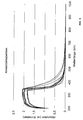
- Figure 2 shows the measured absorption spectra of a variety of different engine oils. The measurements clearly show that the absorption in the range between about 350 and 400 nm decreases very strongly in all products. From a wavelength range of about 500 nm, only a very small absorption is present, which is less than a quarter of that at 300 nm. For most engine oils, fluorescence is even lower. Therefore, it is in accordance with the invention to use fluorescent dyes which absorb and emit in the wavelength range 500 nm to 1000 nm.
- the fuel oil is provided with two fluorescent dyes in specified concentrations, one of which has an emission maximum at 550 nm and the other an emission maximum of 650 nm.
- the light source 3 is accordingly equipped with two LEDs which emit at 490 nm or 570 to 590 nm.
- the detection of the fluorescence caused by the indicators is performed spectrally separated by means of the beam splitter 11 and various filters by two sensors 6, 7, which are designed as semiconductor detectors.
- Various engine oils are marked by various dye mixture ratios of, for example, 1:10, 2:10, 3:10, etc., and 10: 1, 10: 2, etc. Accordingly, the engine oils can be clearly identified on the basis of the measured at the two detectors 6, 7 different measurement signal ratios of 0.1, 0.2, 0.3 to 10. In this example, this results in 19 coding options.
Landscapes
- Health & Medical Sciences (AREA)
- Nuclear Medicine, Radiotherapy & Molecular Imaging (AREA)
- Physics & Mathematics (AREA)
- Life Sciences & Earth Sciences (AREA)
- Chemical & Material Sciences (AREA)
- Analytical Chemistry (AREA)
- Biochemistry (AREA)
- General Health & Medical Sciences (AREA)
- General Physics & Mathematics (AREA)
- Immunology (AREA)
- Pathology (AREA)
- Investigating, Analyzing Materials By Fluorescence Or Luminescence (AREA)
- Investigating Or Analysing Materials By Optical Means (AREA)
Applications Claiming Priority (2)
| Application Number | Priority Date | Filing Date | Title |
|---|---|---|---|
| DE10325537A DE10325537B4 (de) | 2003-06-04 | 2003-06-04 | Vorrichtung und Verfahren zum automatischen Detektieren von wenigstens einem in einem flüssigen Betriebsstoff enthaltenen fluoreszierenden und/oder lichtabsorbierenden Indikator während des Einfüllvorgangs des Betriebsstoffs in eine Maschine |
| PCT/EP2004/005603 WO2004109265A1 (de) | 2003-06-04 | 2004-05-25 | Vorrichtung und verfahren zum automatischen detektieren von wenigstens einem in einem flüssigen betriebsstoff enthaltenen fluoreszierenden und/oder lichtabsorbierenden indikator während des einfüllvorgangs des betriebsstoffs in eine maschine |
Publications (2)
| Publication Number | Publication Date |
|---|---|
| EP1629265A1 EP1629265A1 (de) | 2006-03-01 |
| EP1629265B1 true EP1629265B1 (de) | 2007-01-10 |
Family
ID=33494854
Family Applications (1)
| Application Number | Title | Priority Date | Filing Date |
|---|---|---|---|
| EP04734681A Expired - Lifetime EP1629265B1 (de) | 2003-06-04 | 2004-05-25 | Automatische detektion wenigstens eines in einem flüssigen betriebsstoff enthaltenen fluoreszierenden und/oder lichtabsorbierenden indikators während des einfüllvorgangs des betriebsstoffs in eine maschine |
Country Status (5)
| Country | Link |
|---|---|
| US (1) | US7466400B2 (enExample) |
| EP (1) | EP1629265B1 (enExample) |
| JP (1) | JP4794434B2 (enExample) |
| DE (2) | DE10325537B4 (enExample) |
| WO (1) | WO2004109265A1 (enExample) |
Cited By (1)
| Publication number | Priority date | Publication date | Assignee | Title |
|---|---|---|---|---|
| DE102012020913A1 (de) * | 2012-10-24 | 2014-05-08 | Hochschule Für Angewandte Wissenschaften Coburg | Anordnung und Verfahren für ein Kraftfahrzeug zum Erfassen einer Kraftstoffsorte und/oder Kraftstoffcharakteristik |
Families Citing this family (12)
| Publication number | Priority date | Publication date | Assignee | Title |
|---|---|---|---|---|
| GB0326928D0 (en) * | 2003-11-19 | 2003-12-24 | Johnson Matthey Plc | Apparatus and method for identifying a liquid product |
| US20080160620A1 (en) | 2006-12-28 | 2008-07-03 | United Technologies Corporation | Method for quantitatively determining the dye content in dyed oils |
| GB0819094D0 (en) * | 2008-10-20 | 2008-11-26 | Johnson Matthey Plc | Catalyst containment unit |
| GB0901658D0 (en) * | 2009-02-03 | 2009-03-11 | Johnson Matthey Plc | Methods of measuring fluorescence in liquids |
| JP5646957B2 (ja) * | 2010-11-08 | 2014-12-24 | 三井造船株式会社 | 流体流れの可視化装置および可視化方法 |
| WO2014063725A1 (en) | 2012-10-23 | 2014-05-01 | Opet A.S. | A method and an apparatus for the detection of a tagging material in fluids |
| JP5555870B1 (ja) * | 2014-01-24 | 2014-07-23 | 三晃精機株式会社 | 不正燃料の判別方法及び判別装置 |
| WO2016010494A1 (en) | 2014-07-17 | 2016-01-21 | Kuantag Nanoteknolojiler Geliştirme Ve Üretim A.Ş. | A fluorescent substance detection system |
| US20160371704A1 (en) | 2015-06-18 | 2016-12-22 | Kuantag Nanoteknolojiler Gelistirme Ve Uretim A.S. | Integrated fuel tracking system |
| US11262298B2 (en) * | 2018-08-30 | 2022-03-01 | Caterpillar Inc. | System and method for determining fluid origin |
| KR102180083B1 (ko) * | 2018-11-19 | 2020-11-17 | 주식회사 마하테크 | 엔진오일 산화도 측정장치 |
| FR3105427B1 (fr) * | 2019-12-18 | 2022-04-22 | Renault Sas | Système de détection en temps réel de carburant injecté dans un réservoir à carburant d’un véhicule automobile |
Family Cites Families (22)
| Publication number | Priority date | Publication date | Assignee | Title |
|---|---|---|---|---|
| DE19818176A1 (de) * | 1998-04-23 | 1999-10-28 | Basf Ag | Verfahren zur Markierung von Flüssigkeiten mit mindestens zwei Markierstoffen und Verfahren zu deren Detektion |
| JPS62192634A (ja) * | 1986-02-20 | 1987-08-24 | Tokyu Car Corp | タンクローリ車の油種検出方法 |
| JPS6431037A (en) * | 1987-07-28 | 1989-02-01 | Mitsui Constr | Apparatus for discriminating kind of oil feed through oil feed pipe |
| JPH0538558U (ja) * | 1991-08-02 | 1993-05-25 | カルソニツク株式会社 | オイル劣化検出装置 |
| US5225679A (en) * | 1992-01-24 | 1993-07-06 | Boston Advanced Technologies, Inc. | Methods and apparatus for determining hydrocarbon fuel properties |
| JP2810598B2 (ja) * | 1992-09-09 | 1998-10-15 | 株式会社富永製作所 | 貯留タンクへの混油判定装置 |
| JPH0712723A (ja) * | 1992-09-30 | 1995-01-17 | Mitsubishi Heavy Ind Ltd | 潤滑油劣化度測定装置 |
| WO1994012874A1 (en) * | 1992-11-27 | 1994-06-09 | Bp Oil International Limited | Method of identifying liquid petroleum products |
| JP2963346B2 (ja) * | 1994-08-22 | 1999-10-18 | 株式会社ジャパンエナジー | 潤滑油の劣化検知方法 |
| US5723338A (en) | 1994-11-04 | 1998-03-03 | Amoco Corporation | Tagging hydrocarbons for subsequent identification |
| DE19536836C2 (de) | 1995-10-02 | 2003-11-13 | Alstom | Verfahren zum Betrieb einer Kraftwerksanlage |
| JPH09304281A (ja) * | 1996-05-09 | 1997-11-28 | Tokyo Electric Power Co Inc:The | 油検知装置 |
| DE69712218T2 (de) * | 1996-11-01 | 2002-10-17 | Bp Oil International Ltd., London | Testvorrichtung und verfahren zu deren gebrauch |
| US5958780A (en) | 1997-06-30 | 1999-09-28 | Boston Advanced Technologies, Inc. | Method for marking and identifying liquids |
| EP1054251A4 (en) * | 1998-02-02 | 2001-05-02 | Hitachi Ltd | METHOD AND DEVICE FOR DETERMINING THE AGING OF OIL |
| US6193710B1 (en) | 1998-07-16 | 2001-02-27 | Visx, Incorporated | Method for scanning non-overlapping patterns of laser energy with diffractive optics |
| JP2000130240A (ja) * | 1998-10-26 | 2000-05-09 | Hitachi Ltd | オイル劣化診断装置を具備した自動車 |
| US6274381B1 (en) | 1998-11-09 | 2001-08-14 | Rohm And Haas Company | Method for invisibly tagging petroleum products using visible dyes |
| JP3476124B2 (ja) * | 1998-11-27 | 2003-12-10 | トヨタ自動車株式会社 | 摩擦材の品質評価方法 |
| WO2001036966A2 (en) * | 1999-11-19 | 2001-05-25 | Battelle Memorial Institute | An apparatus for machine fluid analysis |
| DE10053069A1 (de) * | 2000-10-26 | 2002-05-08 | Deutz Ag | Verfahren zur Bestimmung der Schmierölqualität einer Brennkraftmaschine |
| US6836332B2 (en) * | 2001-09-25 | 2004-12-28 | Tennessee Scientific, Inc. | Instrument and method for testing fluid characteristics |
-
2003
- 2003-06-04 DE DE10325537A patent/DE10325537B4/de not_active Expired - Lifetime
-
2004
- 2004-05-25 US US10/559,552 patent/US7466400B2/en not_active Expired - Lifetime
- 2004-05-25 JP JP2006508200A patent/JP4794434B2/ja not_active Expired - Lifetime
- 2004-05-25 WO PCT/EP2004/005603 patent/WO2004109265A1/de not_active Ceased
- 2004-05-25 EP EP04734681A patent/EP1629265B1/de not_active Expired - Lifetime
- 2004-05-25 DE DE502004002631T patent/DE502004002631D1/de not_active Expired - Lifetime
Cited By (2)
| Publication number | Priority date | Publication date | Assignee | Title |
|---|---|---|---|---|
| DE102012020913A1 (de) * | 2012-10-24 | 2014-05-08 | Hochschule Für Angewandte Wissenschaften Coburg | Anordnung und Verfahren für ein Kraftfahrzeug zum Erfassen einer Kraftstoffsorte und/oder Kraftstoffcharakteristik |
| EP2912439B1 (de) * | 2012-10-24 | 2018-08-01 | Hochschule für angewandte Wissenschaften Fachhochschule Coburg | Anordnung und verfahren für ein kraftfahrzeug zum erfassen einer kraftstoffsorte und/oder kraftstoffcharakteristik |
Also Published As
| Publication number | Publication date |
|---|---|
| JP4794434B2 (ja) | 2011-10-19 |
| EP1629265A1 (de) | 2006-03-01 |
| JP2006526771A (ja) | 2006-11-24 |
| US7466400B2 (en) | 2008-12-16 |
| US20070064323A1 (en) | 2007-03-22 |
| DE10325537B4 (de) | 2006-08-17 |
| DE502004002631D1 (de) | 2007-02-22 |
| DE10325537A1 (de) | 2005-01-05 |
| WO2004109265A1 (de) | 2004-12-16 |
Similar Documents
| Publication | Publication Date | Title |
|---|---|---|
| EP1629265B1 (de) | Automatische detektion wenigstens eines in einem flüssigen betriebsstoff enthaltenen fluoreszierenden und/oder lichtabsorbierenden indikators während des einfüllvorgangs des betriebsstoffs in eine maschine | |
| EP2912439B1 (de) | Anordnung und verfahren für ein kraftfahrzeug zum erfassen einer kraftstoffsorte und/oder kraftstoffcharakteristik | |
| DE19826265C2 (de) | Bohrlochsonde zur Untersuchung von Böden | |
| DE69627328T2 (de) | Verfahren und vorrichtungen zur prüfung von beschichtungen | |
| EP1112555B1 (de) | Verfahren und Vorrichtung zur Zustandsprüfung von Wertpapieren mittels einer Dunkelfeldmessung als auch einer Hellfeldmessung. | |
| DE102011055272A1 (de) | Verfahren zur Bestimmung eines relaxationszeitabhängigen Parameters zu einem System | |
| DE1939982A1 (de) | Verfahren und Geraet zur Bestimmung der von einem Material bei Erregung durch Sonnenlicht emittierten Fluoreszenzstrahlung | |
| DE19507119C2 (de) | Vorrichtung zur Bestimmung von Verunreinigungen | |
| DE102014222331B4 (de) | Verfahren zur Quantifizierung der Oxidationsstabilität und/oder des Alterungsgrades eines Kraftstoffes | |
| DE102007025585A1 (de) | Verfahren zum Betreiben eines Verbrennungsmotors und Vorrichtung zur Bestimmung eines Betriebsparameters dessen | |
| DE102018131128A1 (de) | Optischer Sensor | |
| DE102011002080A1 (de) | Vorrichtung und Verfahren zur Bestimmung der Konzentration von Fluorophoren in einer Probe | |
| EP3561487B1 (de) | Messvorrichtung zur analyse einer zusammensetzung eines brenngases mit einer vor einem detektor angeordneten filterkammer | |
| DE102018221700A1 (de) | Verfahren zur Detektion von Partikeln oder Aerosol in einem strömenden Fluid, Computerprogramm sowie elektrisches Speichermedium | |
| DE102016223424A1 (de) | Partikelmessvorrichtung und Verfahren zur Bestimmung einer Partikelgröße | |
| DE102010016801A1 (de) | Fluoreszenz-Detektionseinheit für eine Flüssigchromatographie-Einrichtung | |
| DE102006010100B4 (de) | Vorrichtung und Verfahren zur spektroskopischen Messung | |
| EP1595137A1 (de) | Verfahren und vorrichtungen zur bestimmung und überwachung von verunreinigungszuständen unterschiedlicher flüssigkeiten | |
| WO2002068926A2 (de) | Leckage-suche mit farbstoff | |
| EP1256796B1 (de) | Vorrichtung zur Erfassung der Konzentration einer fluoreszierenden Substanz in einem Fluid, insbesondere in einem Kraftstoff | |
| DE102019101681B3 (de) | Verfahren zum Bestimmen des Einspritzverhaltens einer Wasser-Kraftstoff-Mischung und Teststand | |
| DE8907431U1 (de) | Vorrichtung zur Bestimmung wenigstens einer in Wasser gelösten oder dispergierten fluoreszierenden Substanz | |
| DE102008041609A1 (de) | Verfahren und Vorrichtung zur Bestimmung der Zusammensetzung eines Kraftstoffgemischs | |
| WO2003058219A1 (de) | Verfahren und vorrichtung zur bestimmung von ölkonzentration in wasser | |
| DE102019130589A1 (de) | Behälter zur Füllstandsmessung und Detektion von Füllmedien, Verwendung und Verfahren zur Füllstandsmessung und Detektion von Füllmedien mittels des Behälters |
Legal Events
| Date | Code | Title | Description |
|---|---|---|---|
| PUAI | Public reference made under article 153(3) epc to a published international application that has entered the european phase |
Free format text: ORIGINAL CODE: 0009012 |
|
| 17P | Request for examination filed |
Effective date: 20051221 |
|
| AK | Designated contracting states |
Kind code of ref document: A1 Designated state(s): AT BE BG CH CY CZ DE DK EE ES FI FR GB GR HU IE IT LI LU MC NL PL PT RO SE SI SK TR |
|
| RTI1 | Title (correction) |
Free format text: AUTOMATIC DETECTION OF AT LEAST ONE FLUORESCENT AND/OR LIGHT-ABSORBING INDICATOR CONTAINED IN A LIQUID SERVICE FLUID DURING THE FILLING OF A MACHINE WITH SAID SERVICE FLUID |
|
| GRAP | Despatch of communication of intention to grant a patent |
Free format text: ORIGINAL CODE: EPIDOSNIGR1 |
|
| DAX | Request for extension of the european patent (deleted) | ||
| GRAS | Grant fee paid |
Free format text: ORIGINAL CODE: EPIDOSNIGR3 |
|
| GRAA | (expected) grant |
Free format text: ORIGINAL CODE: 0009210 |
|
| AK | Designated contracting states |
Kind code of ref document: B1 Designated state(s): AT BE BG CH CY CZ DE DK EE ES FI FR GB GR HU IE IT LI LU MC NL PL PT RO SE SI SK TR |
|
| PG25 | Lapsed in a contracting state [announced via postgrant information from national office to epo] |
Ref country code: NL Free format text: LAPSE BECAUSE OF FAILURE TO SUBMIT A TRANSLATION OF THE DESCRIPTION OR TO PAY THE FEE WITHIN THE PRESCRIBED TIME-LIMIT Effective date: 20070110 Ref country code: FI Free format text: LAPSE BECAUSE OF FAILURE TO SUBMIT A TRANSLATION OF THE DESCRIPTION OR TO PAY THE FEE WITHIN THE PRESCRIBED TIME-LIMIT Effective date: 20070110 Ref country code: DK Free format text: LAPSE BECAUSE OF FAILURE TO SUBMIT A TRANSLATION OF THE DESCRIPTION OR TO PAY THE FEE WITHIN THE PRESCRIBED TIME-LIMIT Effective date: 20070110 Ref country code: PL Free format text: LAPSE BECAUSE OF FAILURE TO SUBMIT A TRANSLATION OF THE DESCRIPTION OR TO PAY THE FEE WITHIN THE PRESCRIBED TIME-LIMIT Effective date: 20070110 Ref country code: SI Free format text: LAPSE BECAUSE OF FAILURE TO SUBMIT A TRANSLATION OF THE DESCRIPTION OR TO PAY THE FEE WITHIN THE PRESCRIBED TIME-LIMIT Effective date: 20070110 Ref country code: IE Free format text: LAPSE BECAUSE OF FAILURE TO SUBMIT A TRANSLATION OF THE DESCRIPTION OR TO PAY THE FEE WITHIN THE PRESCRIBED TIME-LIMIT Effective date: 20070110 |
|
| REG | Reference to a national code |
Ref country code: GB Ref legal event code: FG4D Free format text: NOT ENGLISH |
|
| REG | Reference to a national code |
Ref country code: IE Ref legal event code: FG4D Free format text: LANGUAGE OF EP DOCUMENT: GERMAN |
|
| REF | Corresponds to: |
Ref document number: 502004002631 Country of ref document: DE Date of ref document: 20070222 Kind code of ref document: P |
|
| PG25 | Lapsed in a contracting state [announced via postgrant information from national office to epo] |
Ref country code: SE Free format text: LAPSE BECAUSE OF FAILURE TO SUBMIT A TRANSLATION OF THE DESCRIPTION OR TO PAY THE FEE WITHIN THE PRESCRIBED TIME-LIMIT Effective date: 20070410 Ref country code: BG Free format text: LAPSE BECAUSE OF FAILURE TO SUBMIT A TRANSLATION OF THE DESCRIPTION OR TO PAY THE FEE WITHIN THE PRESCRIBED TIME-LIMIT Effective date: 20070410 |
|
| PG25 | Lapsed in a contracting state [announced via postgrant information from national office to epo] |
Ref country code: ES Free format text: LAPSE BECAUSE OF FAILURE TO SUBMIT A TRANSLATION OF THE DESCRIPTION OR TO PAY THE FEE WITHIN THE PRESCRIBED TIME-LIMIT Effective date: 20070421 |
|
| PG25 | Lapsed in a contracting state [announced via postgrant information from national office to epo] |
Ref country code: PT Free format text: LAPSE BECAUSE OF FAILURE TO SUBMIT A TRANSLATION OF THE DESCRIPTION OR TO PAY THE FEE WITHIN THE PRESCRIBED TIME-LIMIT Effective date: 20070611 |
|
| NLV1 | Nl: lapsed or annulled due to failure to fulfill the requirements of art. 29p and 29m of the patents act | ||
| ET | Fr: translation filed | ||
| GBV | Gb: ep patent (uk) treated as always having been void in accordance with gb section 77(7)/1977 [no translation filed] |
Effective date: 20070110 |
|
| REG | Reference to a national code |
Ref country code: IE Ref legal event code: FD4D |
|
| PLBE | No opposition filed within time limit |
Free format text: ORIGINAL CODE: 0009261 |
|
| STAA | Information on the status of an ep patent application or granted ep patent |
Free format text: STATUS: NO OPPOSITION FILED WITHIN TIME LIMIT |
|
| PG25 | Lapsed in a contracting state [announced via postgrant information from national office to epo] |
Ref country code: SK Free format text: LAPSE BECAUSE OF FAILURE TO SUBMIT A TRANSLATION OF THE DESCRIPTION OR TO PAY THE FEE WITHIN THE PRESCRIBED TIME-LIMIT Effective date: 20070110 Ref country code: GB Free format text: LAPSE BECAUSE OF FAILURE TO SUBMIT A TRANSLATION OF THE DESCRIPTION OR TO PAY THE FEE WITHIN THE PRESCRIBED TIME-LIMIT Effective date: 20070110 |
|
| 26N | No opposition filed |
Effective date: 20071011 |
|
| BERE | Be: lapsed |
Owner name: FUCHS PETROLUB A.G. Effective date: 20070531 |
|
| PG25 | Lapsed in a contracting state [announced via postgrant information from national office to epo] |
Ref country code: CZ Free format text: LAPSE BECAUSE OF FAILURE TO SUBMIT A TRANSLATION OF THE DESCRIPTION OR TO PAY THE FEE WITHIN THE PRESCRIBED TIME-LIMIT Effective date: 20070110 Ref country code: RO Free format text: LAPSE BECAUSE OF FAILURE TO SUBMIT A TRANSLATION OF THE DESCRIPTION OR TO PAY THE FEE WITHIN THE PRESCRIBED TIME-LIMIT Effective date: 20070110 |
|
| PG25 | Lapsed in a contracting state [announced via postgrant information from national office to epo] |
Ref country code: MC Free format text: LAPSE BECAUSE OF NON-PAYMENT OF DUE FEES Effective date: 20070531 |
|
| PG25 | Lapsed in a contracting state [announced via postgrant information from national office to epo] |
Ref country code: BE Free format text: LAPSE BECAUSE OF NON-PAYMENT OF DUE FEES Effective date: 20070531 |
|
| PG25 | Lapsed in a contracting state [announced via postgrant information from national office to epo] |
Ref country code: GR Free format text: LAPSE BECAUSE OF FAILURE TO SUBMIT A TRANSLATION OF THE DESCRIPTION OR TO PAY THE FEE WITHIN THE PRESCRIBED TIME-LIMIT Effective date: 20070411 |
|
| PG25 | Lapsed in a contracting state [announced via postgrant information from national office to epo] |
Ref country code: AT Free format text: LAPSE BECAUSE OF NON-PAYMENT OF DUE FEES Effective date: 20070525 |
|
| REG | Reference to a national code |
Ref country code: CH Ref legal event code: PL |
|
| PG25 | Lapsed in a contracting state [announced via postgrant information from national office to epo] |
Ref country code: CH Free format text: LAPSE BECAUSE OF NON-PAYMENT OF DUE FEES Effective date: 20080531 Ref country code: LI Free format text: LAPSE BECAUSE OF NON-PAYMENT OF DUE FEES Effective date: 20080531 Ref country code: EE Free format text: LAPSE BECAUSE OF FAILURE TO SUBMIT A TRANSLATION OF THE DESCRIPTION OR TO PAY THE FEE WITHIN THE PRESCRIBED TIME-LIMIT Effective date: 20070110 |
|
| PG25 | Lapsed in a contracting state [announced via postgrant information from national office to epo] |
Ref country code: CY Free format text: LAPSE BECAUSE OF FAILURE TO SUBMIT A TRANSLATION OF THE DESCRIPTION OR TO PAY THE FEE WITHIN THE PRESCRIBED TIME-LIMIT Effective date: 20070110 |
|
| PG25 | Lapsed in a contracting state [announced via postgrant information from national office to epo] |
Ref country code: LU Free format text: LAPSE BECAUSE OF NON-PAYMENT OF DUE FEES Effective date: 20070525 |
|
| PG25 | Lapsed in a contracting state [announced via postgrant information from national office to epo] |
Ref country code: HU Free format text: LAPSE BECAUSE OF FAILURE TO SUBMIT A TRANSLATION OF THE DESCRIPTION OR TO PAY THE FEE WITHIN THE PRESCRIBED TIME-LIMIT Effective date: 20070711 Ref country code: TR Free format text: LAPSE BECAUSE OF FAILURE TO SUBMIT A TRANSLATION OF THE DESCRIPTION OR TO PAY THE FEE WITHIN THE PRESCRIBED TIME-LIMIT Effective date: 20070110 |
|
| REG | Reference to a national code |
Ref country code: DE Ref legal event code: R082 Ref document number: 502004002631 Country of ref document: DE Representative=s name: REISER & PARTNER PATENTANWAELTE, DE |
|
| REG | Reference to a national code |
Ref country code: DE Ref legal event code: R082 Ref document number: 502004002631 Country of ref document: DE Representative=s name: REISER & PARTNER PATENTANWAELTE MBB, DE Effective date: 20121007 Ref country code: DE Ref legal event code: R082 Ref document number: 502004002631 Country of ref document: DE Representative=s name: REISER & PARTNER PATENTANWAELTE MBB, DE Effective date: 20131002 Ref country code: DE Ref legal event code: R082 Ref document number: 502004002631 Country of ref document: DE Representative=s name: REISER & PARTNER PATENTANWAELTE, DE Effective date: 20121007 Ref country code: DE Ref legal event code: R082 Ref document number: 502004002631 Country of ref document: DE Representative=s name: REISER & PARTNER PATENTANWAELTE, DE Effective date: 20131002 Ref country code: DE Ref legal event code: R081 Ref document number: 502004002631 Country of ref document: DE Owner name: FUCHS PETROLUB SE, DE Free format text: FORMER OWNER: FUCHS PETROLUB AG, 68169 MANNHEIM, DE Effective date: 20131002 |
|
| REG | Reference to a national code |
Ref country code: FR Ref legal event code: CJ Effective date: 20140317 |
|
| REG | Reference to a national code |
Ref country code: FR Ref legal event code: PLFP Year of fee payment: 13 |
|
| REG | Reference to a national code |
Ref country code: FR Ref legal event code: PLFP Year of fee payment: 14 |
|
| REG | Reference to a national code |
Ref country code: FR Ref legal event code: PLFP Year of fee payment: 15 |
|
| P01 | Opt-out of the competence of the unified patent court (upc) registered |
Effective date: 20230505 |
|
| PGFP | Annual fee paid to national office [announced via postgrant information from national office to epo] |
Ref country code: IT Payment date: 20230531 Year of fee payment: 20 Ref country code: FR Payment date: 20230517 Year of fee payment: 20 Ref country code: DE Payment date: 20230519 Year of fee payment: 20 |
|
| REG | Reference to a national code |
Ref country code: DE Ref legal event code: R071 Ref document number: 502004002631 Country of ref document: DE |