EP1629265B1 - Automatic detection of at least one fluorescent and/or light-absorbing indicator contained in a liquid service fluid during the filling of a machine with said service fluid - Google Patents
Automatic detection of at least one fluorescent and/or light-absorbing indicator contained in a liquid service fluid during the filling of a machine with said service fluid Download PDFInfo
- Publication number
- EP1629265B1 EP1629265B1 EP04734681A EP04734681A EP1629265B1 EP 1629265 B1 EP1629265 B1 EP 1629265B1 EP 04734681 A EP04734681 A EP 04734681A EP 04734681 A EP04734681 A EP 04734681A EP 1629265 B1 EP1629265 B1 EP 1629265B1
- Authority
- EP
- European Patent Office
- Prior art keywords
- light
- operating material
- engine
- receiving device
- measuring
- Prior art date
- Legal status (The legal status is an assumption and is not a legal conclusion. Google has not performed a legal analysis and makes no representation as to the accuracy of the status listed.)
- Active
Links
Images

Classifications
-
- G—PHYSICS
- G01—MEASURING; TESTING
- G01N—INVESTIGATING OR ANALYSING MATERIALS BY DETERMINING THEIR CHEMICAL OR PHYSICAL PROPERTIES
- G01N21/00—Investigating or analysing materials by the use of optical means, i.e. using sub-millimetre waves, infrared, visible or ultraviolet light
- G01N21/62—Systems in which the material investigated is excited whereby it emits light or causes a change in wavelength of the incident light
- G01N21/63—Systems in which the material investigated is excited whereby it emits light or causes a change in wavelength of the incident light optically excited
- G01N21/64—Fluorescence; Phosphorescence
- G01N21/6428—Measuring fluorescence of fluorescent products of reactions or of fluorochrome labelled reactive substances, e.g. measuring quenching effects, using measuring "optrodes"
- G01N2021/6439—Measuring fluorescence of fluorescent products of reactions or of fluorochrome labelled reactive substances, e.g. measuring quenching effects, using measuring "optrodes" with indicators, stains, dyes, tags, labels, marks
-
- G—PHYSICS
- G01—MEASURING; TESTING
- G01N—INVESTIGATING OR ANALYSING MATERIALS BY DETERMINING THEIR CHEMICAL OR PHYSICAL PROPERTIES
- G01N21/00—Investigating or analysing materials by the use of optical means, i.e. using sub-millimetre waves, infrared, visible or ultraviolet light
- G01N21/17—Systems in which incident light is modified in accordance with the properties of the material investigated
- G01N21/25—Colour; Spectral properties, i.e. comparison of effect of material on the light at two or more different wavelengths or wavelength bands
- G01N21/31—Investigating relative effect of material at wavelengths characteristic of specific elements or molecules, e.g. atomic absorption spectrometry
Definitions
- the present invention relates to a method for automatically detecting at least one fluorescent and / or light-absorbing indicator contained in a liquid fuel during the filling operation of the fuel into a machine, and to a machine having an apparatus integrated therein for carrying out the method.
- Liquid operating materials for the purposes of the present application are lubricating oil, engine oil and hydraulic oil.
- the quality of a fuel is crucial for the determination of the fuel change interval.
- modern motor vehicles already have on-board computers which calculate or adapt the oil change intervals as a function of various operating parameters.
- the quality of the filled lubricating oil can not be automatically taken into account.
- US Pat. No. 6,274,381 B1 proposes using two or more visible dyes in a fuel whose absorption maxima are at different wavelengths. If a sample of such a labeled fuel is placed in a suitable laboratory instrument, the indicator can be determined. According to US Pat. No. 6,274,381 B1, a light source is used for this purpose and the absorption caused by the indicators is determined.
- US 5,958,780 discloses a measuring device for detecting at least one in a fuel-containing fluorescent and / or light-absorbing indicator with a measuring path formed by a transparent material, which is traversed by the fuel, at least one light source which radiates onto the measuring path, a light receiving device, to the light which passes through the fuel flowing through the measurement path and / or emanates from the indicator due to a fluorescence effect and which generates a corresponding measurement signal dependent on the intensity of the incident light, and an evaluation unit for evaluating the measurement signal.
- the measuring device is arranged on a line leading away from a storage tank, wherein it is not specified in more detail, which is located at the other end of the line.
- No. 5,225,679 discloses a measuring device arranged in a line leading from a storage tank to a motor vehicle for determining the properties of the fuel by means of infrared absorption spectroscopy.
- the object of the present invention is to enable an automatic detection of the identity of a fuel contained in a machine.
- a machine in particular an engine of a vehicle, having an integrated device for automatically detecting at least one fluorescent and / or light-absorbing indicator contained in a liquid operating substance, namely lubricating oil, engine oil or hydraulic oil, during the filling process of the operating material into the vehicle Machine, wherein the device is a filler pipe for the fuel through which the fuel to be filled enters the fuel supply of the machine, formed by a transparent material measuring path, which is at least partially filled or traversed when filling the fuel into the filler pipe with the operating material, at least a light source which radiates onto the measuring path, a light receiving device, which is hit by light which passes through the operating medium when flowing through the measuring path and / or by the indicator due to a Fluorescence effect emanates, and at least one of the strength of the incident light on the light receiving device dependent measurement signal generated, and an evaluation unit, in which the at least one measurement signal of the light receiving device is evaluated comprises.
- a liquid operating substance namely lubricating oil, engine oil or hydraulic oil
- the design according to the invention makes it possible for the first time to automatically detect a liquid operating material, in particular its identity or quality, when it is filled into a machine.
- the invention has recognized that commonly used consumables have in their absorption spectrum areas with a significantly reduced absorption.
- it has been found that in the range of 500 to 1000 nm no or reduced absorption occurs, and therefore offer these areas especially for marking with indicators.
- 500 nm excitation of the fluorescence indicators is well possible because the exciting light is not or hardly absorbed by the fuel.
- the light emitted by the fluorescence indicator can be determined particularly well in the range above 500 nm, since the absorption of the working fluid does not or only slightly influences the measurement result.
- dyes in particular fluorescent dyes
- the apparatus has a measuring section formed by a transparent material which is at least partially filled or flowed through with the operating fluid when the operating fluid is introduced into the machine.
- the or the indicators and their concentration can be measured.
- the resulting measurement signal is then further processed by an evaluation unit. For example, it is possible to compare the measurement signals with data stored in advance in an evaluation matrix and in this way to obtain information about the filled-in substance in the machine. This information can then be further utilized automatically, for example, to calculate a fuel change interval adapted to the quality of the filled fuel.
- the light receiving device has at least two light sensors which have frequency ranges deviating from one another and in each case generate a measuring signal.
- a plurality of indicators can be measured by the device. If one also considers that different concentration thresholds of the indicators can be determined according to the invention, a large number of coding possibilities results.
- concentration thresholds of the indicators can be determined according to the invention, a large number of coding possibilities results.
- two indicators and four concentration levels there are already 16 coding possibilities. Using three dyes and four levels of concentration increases that number to 64 and increases to 256 encoding possibilities using four indicators.
- the light source and the light receiving device are aligned with the measuring path and arranged at an angle of 0 to 170 degrees around the measuring path.
- the light source and the light receiving device are arranged at an angle of 30 to 140, in particular 60 to 120 degrees.
- the filler pipe in the flow direction before the measuring section has a section opening into the measuring section with a cross-sectional reduction.
- This cross-sectional reduction is arranged in particular above the measuring section, wherein it is sufficient if only a partial flow of the filled fuel passes through the measuring section.
- the measuring section is designed as a measuring tube, which opens directly or indirectly in the fuel supply of the machine.
- a further improvement is achieved in that a plurality of light sources are provided which radiate in different frequency ranges, thereby facilitating the detection of different indicators.
- the signal resulting from the evaluation of the measurement signals can be further used in the machine.
- the identity or other information about the filled fuel can be automatically determined and automatically processed, for example, in the on-board computer.
- the start of the machine could be prevented or the operating range could be limited so that no damage to be feared.
- the fuel change interval is calculated or adjusted in dependence on the filled fuel.
- the at least one indicator is a fluorescent dye, which is excited by the light source in the measuring section to fluorescence radiation, wherein the fluorescent radiation forms at least part of the light collected by the light receiving device.
- the operating material contains at least two indicators acting in different frequency ranges and that the indicators, in particular their concentration, are detected by at least two sensors of the light receiving device that are sensitive in the different frequency ranges.
- the measurement signal or signals generated by the light receiving device correlate with the concentration of the at least one indicator in the operating substance.
- one of the indicators of the fuel forms a reference indicator, by means of which the light receiving device generates a reference signal. In this way, in particular the evaluation of the measurement signals can be facilitated.
- the evaluation unit evaluates the at least one measurement signal on the basis of the ratio of the strength of the at least one measurement signal to the strength of the reference signal. In this way, even under variable conditions, e.g. changing filling level of the measuring section with fuel, the concentrations of the indicators contained in the operating material are reliably determined. In this case, it is sufficient to determine the ratio of the indicators by putting the measurement signal (s) in relation to the reference signal.
- the evaluation is particularly simple if the reference indicator is always present in a constant concentration.
- the evaluation unit assigns a quality signal to the at least one measurement signal. This can be done, for example, by comparing the measurement signals determined concentration levels of the various indicators with a table or matrix of values are assigned in each of which combinations of the concentration levels of indicators certain qualities or other information about the fuel.
- the evaluation unit can be integrated, for example, in the on-board computer of a motor vehicle.
- FIG. 1 schematically shows a device for automatically detecting at least one liquid contained in a liquid Indicator displayed during the filling process of the fuel in a machine.
- the device has for filling the fuel to a filler pipe 1 for the fuel.
- each component that enables or facilitates the filling process of fuel into the machine should be considered a filler pipe, regardless of its cross-sectional shape or the ratio of diameter and length.
- the filler pipe may be formed in particular round or square.
- the elongate filler pipe 1 has a circular cross-section.
- the filler pipe of the device is designed and arranged such that filled fuel passes through the filler pipe 1 directly or indirectly into the fuel supply 12, for example, the oil pan of the machine.
- the device has a measuring section 2 formed by a light-transmissive material.
- a measuring section 2 formed by a light-transmissive material.
- this is formed by an existing example of clear plastic or glass pipe section.
- the measuring section 2 is at least partially filled or flowed through when filling the fuel into the filler pipe 1. It is sufficient if only part of the filled fuel flows through the measuring section 2 for measurement purposes.
- the device has a light source 3, which radiates onto the measuring section 2 and is directed onto it.
- the light emanating from the light source 3 may be a focused beam 4, which is focused in particular on the center of the measuring section 2.
- the device furthermore has a light receiving device 5. This is hit by light which passes through the fuel as it flows through the measuring section 2 and / or emits the fuel due to a fluorescence effect (light 14).
- the illustrated light receiving device 5 has two light sensors 6, 7. These have different frequency ranges.
- the maximum of the spectral sensitivity of the light sensors 6, 7 is different and adapted to the indicators used. In this way, the presence and / or the concentration of an indicator in the operating material can be determined by a respective light sensor 6,7.
- a single sensor may be sufficient.
- the light receiving device 5 generates by means of the light sensors 6, 7 in particular a plurality of measurement signals. Shown in FIG. 1 is a measuring signal 8 of the light sensor 6 and a measuring signal 9 of the light sensor 7. As sensors 6, 7 of the light receiving device 5, PIN diodes in particular can be used.
- the light receiving device 5 also has a beam splitter 11, is distributed by the incident light evenly to the light sensors 6,7.
- FIG. 1 also shows an evaluation unit 10 in which the at least one measurement signal 8, 9 of the light receiving device 5 is evaluated.
- the light source 3 and the light receiving device 5 are aligned with the measuring section 2 of the filling tube 1 of the machine and arranged at an angle ⁇ of 0 to 170 degrees around the measuring section 2 around.
- an angle ⁇ of 0 to 170 degrees around the measuring section 2 around an angle of 30 to 140 degrees, preferably 60 to 120 degrees particularly well proven. If the indicators and their concentration in the operating material are to be determined not by fluorescence measurement but by absorption measurement, the light receiving device 5 is placed directly opposite the light source 3, ie in particular at an angle ⁇ of 180 ° thereto.
- the filler pipe 1 has a section 15 with a cross-sectional reduction, which is arranged upstream of the measuring section 2 in the direction of flow. Due to the cross-sectional constriction, a complete filling of the measuring section with the operating material can be achieved.
- the light sources can be formed particularly simply by LEDs and / or laser diodes.
- the LED or laser diodes can have different wavelengths.
- the device shown in FIG. 1 is integrated into a machine, in particular an engine of a vehicle.
- one, preferably two or more different fluorescent dyes are added to the operating materials.
- a concentration in the range 10 -7 to 10 -9 moles is sufficient.
- higher concentrations in particular up to 10 -4 mol.
- Oil-soluble dyes from the group of coumarins, fluoresceins, rhodamines, oxazines and carbocyanines or their oil-soluble modifications can be used as fluorescent dyes. Due to the low concentration of indicators In the operating materials, the intended properties of the operating materials are not or only insignificantly influenced. The dye can not be seen by eye as it is added in very low concentrations.
- fluorescent dyes it is also possible to use non-fluorescent dyes, for example diazo dyes.
- oil-soluble dyes are used, in particular fluorescent dyes having emission maxima in the range from 500 nm to 1000 nm.
- the detection of the indicators used is carried out during the filling process by excitation by the light sources 3, for example LED or laser diodes, in different, matched to the dyes used wavelength ranges.
- the engine oils may be excited at, for example, 370, 490 and / or 570 to 590 nm.
- the light receiving device By the light receiving device then light is collected.
- fluorescent dyes light emitted by the indicator 14 due to the fluorescence effect is collected.
- non-fluorescent dyes the light passing through the fuel is used.
- the sensors 5, 6 of the light receiving device 5 each generate a measuring signal 8, 9, which reflect the intensity of the light 14 striking the light receiving device 5. Accordingly, the presence and the concentration of the indicators in the operating material can be determined by the evaluation unit 10 on the basis of the measurement signals 8, 9.
- a comparison is made with comparison values stored in a table.
- the identity of the filled fuel is determined and generates a quality signal. This makes it possible to automatically detect the identity of the filled fuel or other information about this and machine further processing the information thus obtained.
- the information about the filled fuel can be used to calculate oil change intervals.
- the operation of the machine can be prevented or the operating range can be restricted if a fuel with a lower than the recommended specification is filled.
- the evaluation is made possible by the fact that the measurement signals 8, 9 generated by the light receiving device 5 correlate with the concentration of the at least one indicator in the operating material.
- one of the indicators or dyes of the operating substance forms a reference indicator.
- the idea behind this is to provide the reference indicator either in an alternating or in an always constant concentration in the fuel. If, for example, the light sensor 6 detects the reference indicator, then the resulting measurement signal 8 forms the reference signal.
- the light sensor 7 detects a further indicator of the operating substance and generates a measuring signal 9 dependent on the concentration of this indicator in the operating fluid.
- the concentration of the indicator or the concentration ratio can always be reliably determined of the indicators. This can also be done with changing measuring conditions, for example, when the measuring section 2 is not completely filled with fuel. In this way, under difficult or changing conditions, for example, even without a section 15 with cross-sectional constriction, a good measurement result can be achieved.
- the detection of the indicators when filling fresh oil is performed in the machine, so that decomposition products, soiling or chemical changes of the oil can not affect the detection process.
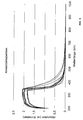
- Figure 2 shows the measured absorption spectra of a variety of different engine oils. The measurements clearly show that the absorption in the range between about 350 and 400 nm decreases very strongly in all products. From a wavelength range of about 500 nm, only a very small absorption is present, which is less than a quarter of that at 300 nm. For most engine oils, fluorescence is even lower. Therefore, it is in accordance with the invention to use fluorescent dyes which absorb and emit in the wavelength range 500 nm to 1000 nm.
- the fuel oil is provided with two fluorescent dyes in specified concentrations, one of which has an emission maximum at 550 nm and the other an emission maximum of 650 nm.
- the light source 3 is accordingly equipped with two LEDs which emit at 490 nm or 570 to 590 nm.
- the detection of the fluorescence caused by the indicators is performed spectrally separated by means of the beam splitter 11 and various filters by two sensors 6, 7, which are designed as semiconductor detectors.
- Various engine oils are marked by various dye mixture ratios of, for example, 1:10, 2:10, 3:10, etc., and 10: 1, 10: 2, etc. Accordingly, the engine oils can be clearly identified on the basis of the measured at the two detectors 6, 7 different measurement signal ratios of 0.1, 0.2, 0.3 to 10. In this example, this results in 19 coding options.
Abstract
Description
Die vorliegende Erfindung betrifft ein Verfahren zum automatischen Detektieren von wenigstens einem in einem flüssigen Betriebsstoff enthaltenen fluoreszierenden und/oder lichtabsorbierenden Indikator während des Einfüllvorgangs des Betriebsstoffs in eine Maschine sowie eine Maschine mit einer darin integrierten Vorrichtung zur Durchführung des Verfahrens.The present invention relates to a method for automatically detecting at least one fluorescent and / or light-absorbing indicator contained in a liquid fuel during the filling operation of the fuel into a machine, and to a machine having an apparatus integrated therein for carrying out the method.
Flüssige Betriebsstoffe im Sinne der vorliegenden Anmeldung sind Schmieröl, Motoröl und Hydrauliköl.Liquid operating materials for the purposes of the present application are lubricating oil, engine oil and hydraulic oil.
Die Auswahl der Betriebsstoffe von Maschinen, insbesondere des Schmieröls bei Verbrennungskraftmaschinen, ist von zunehmender Bedeutung für die Lebensdauer der Maschine. Ein ungeeignetes Öl kann unter Umständen zum sofortigen Ausfall der Maschine führen, während ein besonders hochwertiges Schmieröl eine überdurchschnittliche Einsatzdauer gewährleistet. Beim manuellen Einfüllgang beim Ölwechsel oder beim Nachfüllen können Irrtümer durch die versehentliche Wahl eines ungeeigneten Schmieröls nicht ausgeschlossen werden. Dies ist von zunehmender Bedeutung, da z.B. Kraftfahrzeugmotoren vermehrt auf den jeweiligen Motortyp zugeschnittene und abgestimmte Schmieröle benötigen. Sofern das Einfüllen eines ungeeigneten Betriebsstoffes nicht rechtzeitig erkannt wird, kann es zu erheblichen nachteiligen Auswirkungen, wie z.B. einen vorzeitigen Ausfall der Maschine kommen.The selection of the operating materials of machines, in particular the lubricating oil in internal combustion engines, is of increasing importance for the life of the machine. An unsuitable oil can lead to the immediate failure of the machine under certain circumstances, while a particularly high-quality lubricating oil ensures an above-average service life. During manual oil filling or refilling, errors can not be excluded by accidentally selecting an unsuitable lubricating oil become. This is of increasing importance since, for example, motor vehicle engines increasingly require customized and coordinated lubricating oils for the respective engine type. If the filling of an inappropriate fuel is not detected in time, it can lead to significant adverse effects, such as a premature failure of the machine.
Weiterhin ist die Qualität eines Betriebsstoffs entscheidend für die Bestimmung des Betriebsstoffwechselintervalls. Moderne Kraftfahrzeuge verfügen zwar bereits über Bordrechner, welche die Ölwechselintervalle in Abhängigkeit von verschiedenen Betriebsparametern berechnen bzw. anpassen. Hierbei kann jedoch die Qualität des eingefüllten Schmieröls nicht automatisch berücksichtigt werden.Furthermore, the quality of a fuel is crucial for the determination of the fuel change interval. Although modern motor vehicles already have on-board computers which calculate or adapt the oil change intervals as a function of various operating parameters. However, the quality of the filled lubricating oil can not be automatically taken into account.
In der Patentliteratur sind bereits Farbstoffe zum Markieren von Kraftstoffen bekannt geworden. So schlägt die US 6,274,381 B1 vor in einem Kraftstoff zwei oder mehr sichtbare Farbstoffe einzusetzen, deren Absorptionsmaxima bei unterschiedlichen Wellenlängen liegen. Wird eine Probe eines solchen markierten Kraftstoffes in ein geeignetes Laborgerät gegeben, so kann der Indikator bestimmt werden. Gemäß der US 6,274,381 B1 wird hierzu eine Lichtquelle eingesetzt und die durch die Indikatoren bedingte Absorption ermittelt.Dyes for marking fuels have already become known in the patent literature. Thus, US Pat. No. 6,274,381 B1 proposes using two or more visible dyes in a fuel whose absorption maxima are at different wavelengths. If a sample of such a labeled fuel is placed in a suitable laboratory instrument, the indicator can be determined. According to US Pat. No. 6,274,381 B1, a light source is used for this purpose and the absorption caused by the indicators is determined.
Ein anderes Verfahren ist aus der US 5,928,954 bekannt. In dieser Schrift wird vorgeschlagen, in der zu markierenden Flüssigkeit fluoreszierenden Farbstoff einzusetzen. Die Detektierung des Indikators erfolgt in einem Laborgerät, welches eine Probenaufnahme aufweist, in die eine kleine Menge des zu untersuchenden Stoffes eingebracht wird. Die Probe wird dann mittels Laserdioden bestrahlt und die auftretende, durch den fluoreszierenden Farbstoff bedingte Fluoreszenz gemessen.Another method is known from US 5,928,954. In this document, it is proposed to use fluorescent dye in the liquid to be marked. The indicator is detected in a laboratory device which has a sample receptacle into which a small amount of the substance to be investigated is introduced. The sample is then irradiated by means of laser diodes and the occurring fluorescence caused by the fluorescent dye is measured.
Ein weiterer fluoreszierender Farbstoff für Kraftstoffe ist aus der US 5,729,967 bekannt.Another fluorescent dye for fuels is known from US 5,729,967.
US 5,958,780 offenbart eine Messvorrichtung zur Detektion wenigstens eines in einem Kraftstoff enthaltenden fluoreszierenden und/oder lichtabsorbierenden Indikators miteiner durch ein lichtdurchlässiges Material gebildeten Meßstrecke, die von dem Kraftstoff durchflossen wird, wenigstens einer Lichtquelle, die auf die Meßstrecke strahlt, einem Lichtempfangsgerät, auf das Licht trifft, das durch den durch die Meßstrecke strömenden Kraftstoff hindurchtritt und/oder von dem Indikator aufgrund eines Fluoreszenzeffekts ausgeht und das ein entsprechendes von der Stärke des auftreffenden Lichts abhängiges Meßsignal erzeugt, und einer Auswerteeinheit zur Auswertung des Meßsignals. Die Messvorrichtung ist an einer von einem Vorratstank wegführenden Leitung angeordnet, wobei nicht näher spezifiziert wird, was sich am anderen Ende der Leitung befindet.US 5,958,780 discloses a measuring device for detecting at least one in a fuel-containing fluorescent and / or light-absorbing indicator with a measuring path formed by a transparent material, which is traversed by the fuel, at least one light source which radiates onto the measuring path, a light receiving device, to the light which passes through the fuel flowing through the measurement path and / or emanates from the indicator due to a fluorescence effect and which generates a corresponding measurement signal dependent on the intensity of the incident light, and an evaluation unit for evaluating the measurement signal. The measuring device is arranged on a line leading away from a storage tank, wherein it is not specified in more detail, which is located at the other end of the line.
US 5,225,679 offenbart eine in einer von einem Vorratstank zu einem Kraftfahrzeug führenden Leitung angeordnete Messvorrichtung zur Bestimmung der Eigenschaften des Kraftstoffs mittels Infrarotabsorptionsspektroskopie.No. 5,225,679 discloses a measuring device arranged in a line leading from a storage tank to a motor vehicle for determining the properties of the fuel by means of infrared absorption spectroscopy.
Die vorliegende Erfindung stellt sich die Aufgabe, eine automatische Detektierung der Identität eines in einer Maschine enthaltenen Betriebsstoffes zu ermöglichen.The object of the present invention is to enable an automatic detection of the identity of a fuel contained in a machine.
Diese Aufgabe wird gelöst durch eine Maschine, insbesondere Kraftmaschine eines Fahrzeugs, mit einer darin integrierten Vorrichtung zum automatischen Detektieren von wenigstens einem in einem flüssigen Betriebsstoff, nämlich Schmieröl, Motoröl oder Hydrauliköl, enthaltenen fluoreszierenden und/oder lichtabsorbierenden Indikator während des Einfüllvorgangs des Betriebsstoffs in die Maschine, wobei die Vorrichtung eine Einfüllrohr für den Betriebsstoff, durch welches der einzufüllende Betriebsstoff in den Betriebsstoffvorrat der Maschine gelangt, eine durch ein lichtdurchlässiges Material gebildete Messstrecke, welche beim Einfüllen des Betriebsstoffs in das Einfüllrohr mit dem Betriebsstoff zumindest teilweise gefüllt oder durchflossen wird, wenigstens eine Lichtquelle, welche auf die Messstrecke strahlt, ein Lichtempfangsgerät, auf das Licht trifft, welches beim Durchströmen der Messstrecke durch den Betriebsstoff hindurchtritt und/oder von dem Indikator aufgrund eines Fluoreszenzeffektes ausgeht, und das wenigstens ein von der Stärke des auf das Lichtempfangsgerät auftreffenden Lichts abhängiges Messsignal erzeugt, und eine Auswerteeinheit, in welcher das wenigstens eine Messsignal des Lichtempfangsgeräts ausgewertet wird, aufweist.This object is achieved by a machine, in particular an engine of a vehicle, having an integrated device for automatically detecting at least one fluorescent and / or light-absorbing indicator contained in a liquid operating substance, namely lubricating oil, engine oil or hydraulic oil, during the filling process of the operating material into the vehicle Machine, wherein the device is a filler pipe for the fuel through which the fuel to be filled enters the fuel supply of the machine, formed by a transparent material measuring path, which is at least partially filled or traversed when filling the fuel into the filler pipe with the operating material, at least a light source which radiates onto the measuring path, a light receiving device, which is hit by light which passes through the operating medium when flowing through the measuring path and / or by the indicator due to a Fluorescence effect emanates, and at least one of the strength of the incident light on the light receiving device dependent measurement signal generated, and an evaluation unit, in which the at least one measurement signal of the light receiving device is evaluated comprises.
Durch die erfindungsgemäße Gestaltung ist es erstmals möglich, einen flüssigen Betriebsstoff, insbesondere dessen Identität oder Qualität, automatisch festzustellen, wenn dieser in eine Maschine eingefüllt wird.The design according to the invention makes it possible for the first time to automatically detect a liquid operating material, in particular its identity or quality, when it is filled into a machine.
Die Erfindung hat erkannt, dass üblicherweise verwendete Betriebsstoffe in ihrem Absorptionsspektrum Bereiche mit einer deutlich verringerten Absorption aufweisen. Für Schmieröle hat sich ergeben, dass im Bereich von 500 bis 1000 nm keine oder eine verminderte Absorption auftritt, und sich mithin diese Bereiche zur Markierung mit Indikatoren besonders anbieten. Im Bereich oberhalb 500 nm ist eine Anregung der Fluoreszenzindikatoren gut möglich, da das anregende Licht nicht oder kaum durch den Betriebsstoff absorbiert wird. Gleichermaßen kann auch das vom Fluoreszenzindikator emittierte Licht in dem Bereich über 500 nm besonders gut bestimmt werden, da die Absorption des Betriebsstoffs das Messergebnis nicht oder nur wenig beeinflusst.The invention has recognized that commonly used consumables have in their absorption spectrum areas with a significantly reduced absorption. For lubricating oils, it has been found that in the range of 500 to 1000 nm no or reduced absorption occurs, and therefore offer these areas especially for marking with indicators. In the range above 500 nm excitation of the fluorescence indicators is well possible because the exciting light is not or hardly absorbed by the fuel. Equally, the light emitted by the fluorescence indicator can be determined particularly well in the range above 500 nm, since the absorption of the working fluid does not or only slightly influences the measurement result.
Erfindungsgemäß können Farbstoffe, insbesondere fluoreszierende Farbstoffe als Indikatoren dem Betriebsstoff zugesetzt werden. Diese können durch die in die erfindungsgemäße Maschine integrierte Vorrichtung beim Einfüllen des Betriebsstoff in die Maschine automatisch detektiert werden. Dementsprechend weist die Vorrichtung neben einem Einfüllrohr für den Betriebsstoff eine durch ein lichtdurchlässiges Material gebildete Messstrecke auf, welche beim Einfüllen des Betriebsstoffs in die Maschine mit dem Betriebsstoff zumindest teilweise gefüllt oder durchflossen wird. Mit Hilfe der Lichtquelle und des Lichtempfangsgeräts können der bzw. die Indikatoren und deren Konzentration gemessen werden. Das hieraus resultierende Messsignal wird dann durch eine Auswerteeinheit weiter verarbeitet. Zum Beispiel ist es möglich die Messsignale mit vorab in einer Auswertungsmatrix gespeicherten Daten zu vergleichen und auf diese Weise eine Information über den eingefüllten Betriebsstoff in der Maschine zu erhalten. Diese Information kann dann automatisch weiter verwertet werden, beispielsweise zur Berechnung eines an die Qualität des eingefüllten Betriebsstoffs angepassten Betriebsstoffwechselintervalls.According to the invention, dyes, in particular fluorescent dyes, can be added as indicators to the operating substance. These can be automatically detected by the device integrated in the machine according to the invention when filling the operating material into the machine. Accordingly, in addition to a filler pipe for the operating material, the apparatus has a measuring section formed by a transparent material which is at least partially filled or flowed through with the operating fluid when the operating fluid is introduced into the machine. With the help of the light source and the light receiving device, the or the indicators and their concentration can be measured. The resulting measurement signal is then further processed by an evaluation unit. For example, it is possible to compare the measurement signals with data stored in advance in an evaluation matrix and in this way to obtain information about the filled-in substance in the machine. This information can then be further utilized automatically, for example, to calculate a fuel change interval adapted to the quality of the filled fuel.
Gemäß einer vorteilhaften Ausgestaltung ist vorgesehen, dass das Lichtempfangsgerät wenigstens zwei Lichtsensoren aufweist, welche von einander abweichende Frequenzbereiche aufweisen und jeweils ein Messsignal erzeugen. Auf diese Weise können von der Vorrichtung eine Mehrzahl von Indikatoren gemessen werden. Berücksichtigt man zudem, dass erfindungsgemäß unterschiedliche Konzentrationsschwellen der Indikatoren bestimmt werden können, so ergibt sich eine Vielzahl von Kodierungsmöglichkeiten. Bei der Verwendung von zwei Indikatoren und vier Konzentrationsstufen ergeben sich bereits 16 Kodierungsmöglichkeiten. Bei der Verwendung von drei Farbstoffen und vier Konzentrationsstufen erhöht sich diese Anzahl auf 64 und steigt bei der Verwendung von vier Indikatoren auf 256 Codierungsmöglichkeiten.According to an advantageous embodiment, it is provided that the light receiving device has at least two light sensors which have frequency ranges deviating from one another and in each case generate a measuring signal. In this way, a plurality of indicators can be measured by the device. If one also considers that different concentration thresholds of the indicators can be determined according to the invention, a large number of coding possibilities results. When using two indicators and four concentration levels, there are already 16 coding possibilities. Using three dyes and four levels of concentration increases that number to 64 and increases to 256 encoding possibilities using four indicators.
Gemäß einer vorteilhaften Ausgestaltung der Erfindung ist vorgesehen, dass die Lichtquelle und das Lichtempfangsgerät auf die Messstrecke ausgerichtet und in einem Winkel von 0 bis 170 Grad um die Messstrecke angeordnet sind. Besonders vorteilhafterweise sind Lichtquelle und Lichtempfangsgerät in einem Winkel von 30 bis 140, insbesondere 60 bis 120 Grad angeordnet. Hierdurch wird bei der Verwendung von fluoreszierenden Farbstoffen ein besonders gutes Messsignal erreicht.According to an advantageous embodiment of the invention, it is provided that the light source and the light receiving device are aligned with the measuring path and arranged at an angle of 0 to 170 degrees around the measuring path. Particularly advantageously, the light source and the light receiving device are arranged at an angle of 30 to 140, in particular 60 to 120 degrees. As a result, a particularly good measurement signal is achieved when using fluorescent dyes.
Gemäß einer vorteilhaften Ausgestaltung der Erfindung ist vorgesehen, dass das Einfüllrohr in Durchflussrichtung vor der Messstrecke einen in die Messstrecke mündenden Abschnitt mit einer Querschnittsverringerung aufweist. Diese Querschnittsverringerung ist insbesondere oberhalb der Messstrecke angeordnet, wobei es genügt, wenn nur ein Teilstrom des eingefüllten Betriebsstoffes durch die Messstrecke hindurchtritt. Vorteil dieser Gestaltung ist, dass aufgrund der Querschnittsverringerung eine vollständige Füllung der Messstrecke und damit konstante und bekannte Messbedingungen erreicht werden können.According to an advantageous embodiment of the invention it is provided that the filler pipe in the flow direction before the measuring section has a section opening into the measuring section with a cross-sectional reduction. This cross-sectional reduction is arranged in particular above the measuring section, wherein it is sufficient if only a partial flow of the filled fuel passes through the measuring section. Advantage of this design is that due to the reduction in cross-sectional area a full filling of the Measuring section and thus constant and known measurement conditions can be achieved.
Erfindungsgemäß ist weiterhin vorgesehen, dass die Messstrecke als Messrohr ausgebildet ist, das direkt oder indirekt in den Betriebsstoffvorrat der Maschine mündet.According to the invention it is further provided that the measuring section is designed as a measuring tube, which opens directly or indirectly in the fuel supply of the machine.
Eine weitere Verbesserung wird dadurch erreicht, dass mehrere Lichtquellen vorgesehen sind, welche in voneinander abweichenden Frequenzbereichen strahlen, hierdurch wird die Detektierung von verschiedenen Indikatoren erleichtert.A further improvement is achieved in that a plurality of light sources are provided which radiate in different frequency ranges, thereby facilitating the detection of different indicators.
Gemäß einer vorteilhaften Ausgestaltung der Erfindung ist vorgesehen, dass die Lichtquellen durch LED und/ oder Laserdioden mit unterschiedlichen Wellenlängen gebildet werden. Die vorliegende Erfindung sieht darüber hinaus ein Verfahren vor, zum automatischen Detektieren von wenigstens einem in einem flüssigen Betriebsstoff, nämlich Schmieröl, Motoröl oder Hydrauliköl, enthaltenen fluoreszierenden oder lichtabsorbierenden Indikator während des Einfüllvorgangs des Betriebsstoffs in eine Maschine, insb. eine Kraftmaschine eines Fahrzeugs, mit folgenden Schritten:
- Einfüllen des zu detektierenden Betriebsstoffs in ein Einfüllhrohr, durch das der Betriebsstoff in den Betriebsstoffvorrat der Maschine gelangt und wobei der flüssige Betriebsstoff eine Meßstrecke wenigstens teilweise füllt oder durchfließt,
- Bestrahlung des zu detektierenden Betriebsstoffes in des Meßstrecke mit wenigstens einer Lichtquelle,
- Auffangen von Licht, welches den Betriebsstoff in der Messstrecke durchtritt und/oder von dem in diesem enthaltenen Indikator aufgrund eines Fluoreszenzeffektes ausgeht, durch ein Lichtempfangsgerät, wobei die Intensität des Lichts von dem wenigstens einen Indikator oder dessen Konzentration beeinflusst wird,
- Erzeugen wenigstens eines die Intensität des auf das Lichtempfangsgeräts treffenden Lichts widergebenden Messsignals,
- Auswertung des wenigstens einen Messsignals in einer Auswerteeinheit und Vergleich mit gespeicherten Werten.
- Filling the fuel to be detected in a Einfüllhrohr through which the fuel enters the fuel supply of the machine and wherein the liquid fuel at least partially fills or flows through a measuring path,
- Irradiation of the fuel to be detected in the test section with at least one light source,
- Collecting light which passes through the fuel in the measurement path and / or emanates from the indicator contained therein due to a fluorescence effect, by a light receiving device, wherein the intensity of the light is influenced by the at least one indicator or its concentration,
- Generating at least one measurement signal that reflects the intensity of the light striking the light receiving device,
- Evaluation of the at least one measurement signal in an evaluation unit and comparison with stored values.
Vorteilhaft ist hierbei, dass das sich aus der Auswertung der Messsignale ergebende Signal in der Maschine weiter verwendet werden kann. Beispielsweise kann die Identität oder eine andere Information über den eingefüllten Betriebsstoffs automatisch bestimmt und automatisch, beispielsweise im Bordcomputer weiter verarbeitet werden. So könnte für den Fall, dass ein ungeeigneter Betriebsstoff eingefüllt wird, das Starten der Maschine verhindert oder der Betriebsbereich so beschränkt werden, dass keine Schäden zu befürchten sind. Zudem ist es möglich, dass aufgrund der erzeugten Signale der Betriebsstoffwechselintervall in Abhängigkeit vom eingefüllten Betriebsstoff berechnet oder angepasst wird.It is advantageous here that the signal resulting from the evaluation of the measurement signals can be further used in the machine. For example, the identity or other information about the filled fuel can be automatically determined and automatically processed, for example, in the on-board computer. Thus, in the event that an unsuitable fuel is filled, the start of the machine could be prevented or the operating range could be limited so that no damage to be feared. In addition, it is possible that due to the signals generated, the fuel change interval is calculated or adjusted in dependence on the filled fuel.
Vorteilhafterweise ist der wenigstens eine Indikator ein fluoreszierender Farbstoff, der durch die Lichtquelle in der Messstrecke zu einer Fluoreszenzstrahlung angeregt wird, wobei die Fluoreszenzstrahlung wenigstens einen Teil des durch das Lichtempfangsgerät aufgefangenen Lichts bildet.Advantageously, the at least one indicator is a fluorescent dye, which is excited by the light source in the measuring section to fluorescence radiation, wherein the fluorescent radiation forms at least part of the light collected by the light receiving device.
Eine weitere Verbesserung wird dadurch erzielt, dass der Betriebsstoff wenigstens zwei in verschiedenen Frequenzbereichen wirkende Indikatoren enthält und das durch wenigstens zwei in den unterschiedlichen Frequenzbereichen sensible Sensoren des Lichtempfangsgeräts die Indikatoren, insbesondere deren Konzentration, detektiert werden.A further improvement is achieved in that the operating material contains at least two indicators acting in different frequency ranges and that the indicators, in particular their concentration, are detected by at least two sensors of the light receiving device that are sensitive in the different frequency ranges.
Erfindungsgemäß ist weiterhin vorgesehen, dass das oder die von dem Lichtempfangsgerät erzeugten Messsignale mit der Konzentration des wenigstens einen Indikators in den Betriebsstoff korrelieren.According to the invention, it is further provided that the measurement signal or signals generated by the light receiving device correlate with the concentration of the at least one indicator in the operating substance.
Besonders vorteilhafterweise bildet einer der Indikatoren des Betriebsstoffes einen Referenzindikator, anhand dessen das Lichtempfangsgerät ein Referenzsignal generiert. Auf diese Weise kann insbesondere die Auswertung der Messsignale erleichtert werden.Particularly advantageously, one of the indicators of the fuel forms a reference indicator, by means of which the light receiving device generates a reference signal. In this way, in particular the evaluation of the measurement signals can be facilitated.
Gemäß einer Weiterbildung dieses Erfindungsgedankens ist vorgesehen, dass die Auswerteeinheit anhand des Verhältnisses der Stärke des wenigstens einen Messsignals zu der Stärke des Referenzsignals das wenigstens eine Messsignal auswertet. Auf diese Weise kann, auch unter veränderlichen Bedingungen, wie z.B. wechselndem Füllungsgrad der Messstrecke mit Betriebsstoff, die Konzentrationen der in dem Betriebsstoff enthaltenen Indikatoren zuverlässig bestimmt werden. Hierbei genügt es, das Verhältnis der Indikatoren zu bestimmen, indem das bzw. die Messsignale mit dem Referenzsignal ins Verhältnis gesetzt werden. Besonders einfach ist die Auswertung dann, wenn der Referenzindikator in stets gleichbleibender Konzentration vorhanden ist.According to one development of this inventive concept, it is provided that the evaluation unit evaluates the at least one measurement signal on the basis of the ratio of the strength of the at least one measurement signal to the strength of the reference signal. In this way, even under variable conditions, e.g. changing filling level of the measuring section with fuel, the concentrations of the indicators contained in the operating material are reliably determined. In this case, it is sufficient to determine the ratio of the indicators by putting the measurement signal (s) in relation to the reference signal. The evaluation is particularly simple if the reference indicator is always present in a constant concentration.
Eine weitere Verbesserung wird dadurch erreicht, dass die Auswerteeinheit dem wenigstens einen Messsignal ein Qualitätssignal zuordnet. Dies kann beispielsweise durch Vergleich der durch die Messsignale bestimmten Konzentrationsstufen der verschiedenen Indikatoren mit einer Tabelle oder Wertematrix erfolgen, in der jeweils Kombinationen der Konzentrationsstufen von Indikatoren bestimmte Qualitäten oder andere Informationen über den Betriebsstoff zugeordnet werden. Die Auswerteeinheit kann dabei z.B. in den Bordcomputer eines Kraftfahrzeuges integriert sein.A further improvement is achieved in that the evaluation unit assigns a quality signal to the at least one measurement signal. This can be done, for example, by comparing the measurement signals determined concentration levels of the various indicators with a table or matrix of values are assigned in each of which combinations of the concentration levels of indicators certain qualities or other information about the fuel. The evaluation unit can be integrated, for example, in the on-board computer of a motor vehicle.
Eine weitere Verbesserung wird dann erreicht, wenn das Qualitätssignal für die automatische Bestimmung des Zeitpunkts für den nächsten Betriebsstoffwechsel verwendet wird. Auf diese Weise kann erstmals in die Berechnung oder Anpassung des Service-Intervalls bzw. Betriebsstoffwechsels die Qualität und Herkunft des eingefüllten Betriebsstoffes berücksichtigt werden.Further improvement is achieved when the quality signal is used to automatically determine the time for the next fuel change. In this way, the quality and origin of the filled fuel can be considered for the first time in the calculation or adjustment of the service interval or fuel change.
Weitere Ziele, Merkmale, Vorteile und Anwendungsmöglichkeiten der vorliegenden Erfindung ergeben sich aus der nachfolgenden Beschreibung von Ausführungsbeispielen anhand der Zeichnung.Other objects, features, advantages and applications of the present invention will become apparent from the following description of embodiments with reference to the drawings.
Es zeigen
- Figur 1: Eine schematische Darstellung einer in einer erfindungsgemäßen Vorrichtung;
- Figur 2: Die Absorptionsspektren verschiedener Schmieröle.
- FIG. 1: a schematic representation of a device according to the invention;
- Figure 2: The absorption spectra of various lubricating oils.
In Figur 1 ist schematisch eine Vorrichtung zum automatischen Detektieren von wenigstens einem in einem flüssigen Betriebsstoff ent-haltenen Indikator während des Einfüllvorgangs des Betriebsstoffs in eine Maschine dargestellt.FIG. 1 schematically shows a device for automatically detecting at least one liquid contained in a liquid Indicator displayed during the filling process of the fuel in a machine.
Die Vorrichtung weist zum Einfüllen des Betriebsstoffs ein Einfüllrohr 1 für den Betriebsstoff auf. In der vorliegenden Anmeldung soll jedes den Einfüllvorgang von Betriebsstoff in die Maschine ermöglichende bzw. erleichternde Bauteil als Einfüllrohr gelten, unabhängig von dessen Querschnittsform oder dem Verhältnis von Durchmesser und Länge. Das Einfüllrohr kann insbesondere rund oder eckig ausgebildet sein. Bei der dargestellten Ausführungsform weist das längliche Einfüllrohr 1 einen kreisförmigen Querschnitt auf. Dabei ist das Einfüllrohr der Vorrichtung derart ausgebildet und angeordnet, dass eingefüllter Betriebsstoff durch das Einfüllrohr 1 unmittelbar oder mittelbar in den Betriebsstoffvorrat 12, beispielsweise die Ölwanne der Maschine gelangt.The device has for filling the fuel to a
Die Vorrichtung weist darüber hinaus eine durch ein lichtdurchlässiges Material gebildete Messstrecke 2 auf. Bei der in Figur 1 dargestellten Ausführungsform wird diese durch ein beispielsweise aus klarem Kunststoff oder Glas bestehendem Rohrabschnitt gebildet. Die Messstrecke 2 wird beim Einfüllen des Betriebsstoffs in das Einfüllrohr 1 zumindest teilweise gefüllt oder durchflossen. Dabei ist es ausreichend, wenn nur ein Teil des eingefüllten Betriebsstoffs zu Messzwecken durch die Messstrecke 2 fließt.In addition, the device has a
Weiterhin weist die Vorrichtung eine Lichtquelle 3 auf, welche auf die Messstrecke 2 strahlt und auf diese gerichtet ist. Bei dem von der Lichtquelle 3 ausgehenden Licht kann es sich um einen gebündelten Strahl 4 handeln, welcher insbesondere auf die Mitte der Messstrecke 2 fokussiert ist.Furthermore, the device has a
Die Vorrichtung weist darüber hinaus ein Lichtempfangsgerät 5 auf. Auf dieses trifft Licht welches durch den Betriebsstoff beim Durchströmen der Messstrecke 2 hindurch tritt und/oder dem Betriebsstoff aufgrund eines Fluoreszenzeffektes ausgeht (Licht 14).The device furthermore has a
Das dargestellte Lichtempfangsgerät 5 weist zwei Lichtsensoren 6, 7 auf. Diese haben von einander abweichende Frequenzbereiche. Die Maxima der spektralen Empfindlichkeit der Lichtsensoren 6, 7 ist verschieden und an die eingesetzten Indikatoren angepasst. Auf diese Weise kann durch je einen Lichtsensor 6,7 das Vorhandensein und/oder die Konzentration eines Indikators in dem Betriebsstoff bestimmt werden. Zusätzlich zu den dargestellten zwei Sensoren können auch weitere Sensoren vorgesehen werden, wobei erfindungsgemäß auch ein einziger Sensor ausreichend sein kann.The illustrated
Das Lichtempfangsgerät 5 erzeugt mittels der Lichtsensoren 6, 7 insbesondere mehrere Messsignale. Dargestellt in Figur 1 ist ein Messsignal 8 des Lichtsensors 6 und ein Messsignal 9 des Lichtsensors 7. Als Sensoren 6, 7 des Lichtempfangsgeräts 5 können insbesondere PIN-Dioden eingesetzt werden. Das Lichtempfangsgerät 5 weist zudem einen Strahlteiler 11 auf, durch den eintreffendes Licht gleichmäßig auf die Lichtsensoren 6,7 verteilt wird.The
Figur 1 zeigt darüber hinaus eine Auswerteeinheit 10 in welcher das wenigstens eine Messsignal 8, 9 des Lichtempfangsgeräts 5 ausgewertet wird.FIG. 1 also shows an
Die Lichtquelle 3 und das Lichtempfangsgerät 5 sind auf die Messstrecke 2 des Einfüllrohres 1 der Maschine ausgerichtet und in einem Winkel α von 0 bis 170 Grad um die Messstrecke 2 herum angeordnet. Hierbei hat sich ein Winkel von 30 bis 140 Grad, vorzugsweise 60 bis 120 Grad besonders bewährt. Sofern die Indikatoren und ihre Konzentration in dem Betriebsstoff nicht durch Fluoreszenzmessung sondern durch Absorptionsmessung bestimmt werden sollen, wird das Lichtempfangsgerät 5 direkt gegenüber der Lichtquelle 3, also insbesondere in einem Winkel α von 180° zu dieser angeordnet.The
Bei der in Figur 1 dargestellten Ausführungsform der Vorrichtung weist das Einfüllrohr 1 einen Abschnitt 15 mit einer Querschnittsverringerung auf, der in Durchflussrichtung vor der Messstrecke 2 angeordnet ist. Aufgrund der Querschnittsverengung kann eine vollständige Füllung der Messstrecke mit dem Betriebsstoff erreicht werden.In the embodiment of the device shown in FIG. 1, the
Weiterhin kann vorgesehen sein, dass zusätzlich zur dargestellten Lichtquelle 3 weitere Lichtquellen vorgesehen sind, die in einem von der Lichtquelle 3 abweichenden Frequenzbereich strahlen.Furthermore, it can be provided that in addition to the illustrated
Die Lichtquellen können erfindungsgemäß besonders einfach durch LED und/oder Laserdioden gebildet werden. Die LED bzw. Laserdioden können unterschiedliche Wellenlängen haben.According to the invention, the light sources can be formed particularly simply by LEDs and / or laser diodes. The LED or laser diodes can have different wavelengths.
Erfindungsgemäß ist die in Figur 1 dargestellte Vorrichtung in eine Maschine, insbesondere eine Kraftmaschine eines Fahrzeugs integriert.According to the invention, the device shown in FIG. 1 is integrated into a machine, in particular an engine of a vehicle.
Als Indikatoren werden den Betriebsstoffen einer, vorzugsweise zwei oder mehr verschiedene Fluoreszenzfarbstoffe hinzugefügt. Hierfür ist bereits eine Konzentration im Bereich 10-7 bis 10-9 Mol ausreichend. Es können jedoch auch höhere Konzentrationen, insb. bis 10-4 Mol verwendet werden. Als Fluoreszenzfarbstoffe können öllösliche Farbstoffe aus der Gruppe der Coumarine, Fluoresceine, Rhodamine, Oxazine und Carbocyanine oder deren öllösliche Modifikationen eingesetzt werden. Aufgrund der niedrigen Konzentration der Indikatoren in den Betriebsstoffen werden die bestimmungsgemäßen Eigenschaften der Betriebsstoffe nicht oder nur unwesentlich beeinflusst. Der Farbstoff kann mit dem Auge nicht gesehen werden, da er in sehr niedrigen Konzentrationen zugegeben wird. Alternativ oder zusätzlich zu Fluoreszenzfarbstoffen können auch nicht fluoreszierende Farbstoffe, z.B. Diazofarbstoffe eingesetzt werden. Erfindungsgemäß werden öllösliche Farbstoffe eingesetzt, insbesondere Fluoreszenzfarbstoffe mit Emissionsmaxima in dem Bereich 500 nm bis 1000 nm.As indicators, one, preferably two or more different fluorescent dyes are added to the operating materials. For this purpose, a concentration in the
Die Detektierung der eingesetzten Indikatoren erfolgt beim Einfüllvorgang durch Anregung durch die Lichtquellen 3, beispielsweise LED oder Laserdioden, in unterschiedlichen, auf die eingesetzten Farbstoffe abgestimmten Wellenlängenbereichen. In Abhängigkeit von den Fluoreszenzfarbstoffen können die Motoröle beispielsweise bei 370, 490 und/oder 570 bis 590 nm angeregt werden.The detection of the indicators used is carried out during the filling process by excitation by the
Durch das Lichtempfangsgerät wird sodann Licht aufgefangen. Bei der Verwendung von Fluoreszenzfarbstoffen wird von dem Indikator aufgrund des Fluoreszenzeffektes emittiertes Licht 14 aufgefangen. Bei Verwendung nicht fluoreszierender Farbstoffe wird das Licht verwendet, welches durch den Betriebsstoff hindurchtritt.By the light receiving device then light is collected. When using fluorescent dyes light emitted by the
Die Sensoren 5, 6 des Lichtempfangsgeräts 5 erzeugen jeweils ein Messsignal 8, 9, welches die Intensität des auf das Lichtempfangsgerät 5 treffenden Lichts 14 wiedergeben. Dementsprechend kann durch die Auswerteeinheit 10 anhand der Messsignale 8, 9 das Vorhandensein sowie die Konzentration der Indikatoren in dem Betriebsstoff ermittelt werden.The
Anhand eines Vergleichs der so ermittelten Konzentrationen bzw. Konzentrationsstufen der verschiedenen Indikatoren erfolgt ein Vergleich mit in einer Tabelle abgelegten Vergleichswerten. In Abhängigkeit hiervon wird die Identität des eingefüllten Betriebsstoffs ermittelt und ein Qualitätssignal erzeugt. Hierdurch ist es möglich, automatisch die Identität des eingefüllten Betriebsstoffes oder eine andere Information über diesen zu detektieren und die so erhalten Information maschinell weiterzuverarbeiten. Die Information über den eingefüllten Betriebsstoff kann zur Berechnung von Ölwechselintervallen verwendet werden. Zudem kann der Betrieb der Maschine unterbunden bzw. der Betriebsbereich eingeschränkt werden, sofern ein Betriebsstoff mit einer geringeren als der empfohlenen Spezifikation eingefüllt wird.On the basis of a comparison of the concentrations or concentration levels of the various indicators thus determined, a comparison is made with comparison values stored in a table. Dependent on From this, the identity of the filled fuel is determined and generates a quality signal. This makes it possible to automatically detect the identity of the filled fuel or other information about this and machine further processing the information thus obtained. The information about the filled fuel can be used to calculate oil change intervals. In addition, the operation of the machine can be prevented or the operating range can be restricted if a fuel with a lower than the recommended specification is filled.
Die Auswertung wird dabei dadurch ermöglicht, dass die von dem Lichtempfangsgerät 5 erzeugten Messsignale 8, 9 mit der Konzentration des wenigstens einen Indikators in dem Betriebsstoff korrelieren.The evaluation is made possible by the fact that the measurement signals 8, 9 generated by the
Erfindungsgemäß kann zudem vorgesehen sein, dass einer der Indikatoren bzw. Farbstoffe des Betriebsstoffes ein Referenzindikator bildet. Dahinter steckt die Idee, den Referenzindikator entweder in einer wechselnden oder einer stets gleichbleibenden Konzentration in dem Betriebsstoff vorzusehen. Wenn beispielsweise der Lichtsensor 6 den Referenzindikator detektiert, so bildet das hieraus resultierende Messsignal 8 das Referenzsignal. Der Lichtsensor 7 detektiert hingegen einen weiteren Indikator des Betriebsstoffes und erzeugt ein von der Konzentration dieses Indikators in dem Betriebsstoff abhängiges Messsignal 9. In dem nun das Messsignal 9 mit dem Referenzsignal 8 ins Verhältnis gesetzt wird, kann stets zuverlässig die Konzentration des Indikators oder das Konzentrationsverhältnis der Indikatoren ermittelt werden. Dies kann auch bei wechselnden Messbedingungen erfolgen, z.B. dann, wenn die Messstrecke 2 nicht vollständig mit Betriebsstoff gefüllt ist. Auf diese Weise kann unter schwierigen oder wechselnden Bedingungen, z.B. auch ohne einen Abschnitt 15 mit Querschnittverengung, ein gutes Messergebnis erzielt werden.According to the invention, it can also be provided that one of the indicators or dyes of the operating substance forms a reference indicator. The idea behind this is to provide the reference indicator either in an alternating or in an always constant concentration in the fuel. If, for example, the light sensor 6 detects the reference indicator, then the resulting
Erfindungsgemäß wird die Detektierung der Indikatoren beim Einfüllen von Frischöl in die Maschine durchgeführt, so dass Zersetzungsprodukte, Verschmutzungen oder chemische Änderungen des Öls den Detektierungsvorgang nicht beeinflussen können.According to the invention, the detection of the indicators when filling fresh oil is performed in the machine, so that decomposition products, soiling or chemical changes of the oil can not affect the detection process.
Figur 2 zeigt die gemessenen Absorptionsspektren einer Vielzahl von verschiedenen Motorenölen. Die Messungen zeigen deutlich, dass die Absorption in dem Bereich zwischen etwa 350 und 400 nm bei sämtlichen Produkten sehr stark abnimmt. Ab einem Wellenlängenbereich von etwa 500 nm liegt eine nur noch sehr geringe Absorption vor, welche weniger als ein Viertel derjenigen bei 300 nm beträgt. Für die meisten Motorenöle liegt die Fluoreszenz sogar noch wesentlich darunter. Daher bietet es sich erfindungsgemäß an, Fluoreszenzfarbstoffe zu verwenden, welche in dem Wellenlängenbereich 500 nm bis 1000 nm absorbieren und emittieren.Figure 2 shows the measured absorption spectra of a variety of different engine oils. The measurements clearly show that the absorption in the range between about 350 and 400 nm decreases very strongly in all products. From a wavelength range of about 500 nm, only a very small absorption is present, which is less than a quarter of that at 300 nm. For most engine oils, fluorescence is even lower. Therefore, it is in accordance with the invention to use fluorescent dyes which absorb and emit in the
Beispiel: Der Betriebsstoff Motoröl wird mit zwei Fluoreszenzfarbstoffen in vorgegebenen Konzentrationen versehen, von denen der eine ein Emissionsmaximum bei 550 nm und der andere ein Emissionsmaximum von 650 nm aufweist. Die Lichtquelle 3 wird dementsprechend mit zwei LED's bestückt, die bei 490 nm oder 570 bis 590 nm emittieren. Die Detektierung der durch die Indikatoren hervorgerufenen Fluoreszenz erfolgt spektral separiert mit Hilfe des Strahlteilers 11 und verschiedenen Filtern durch zwei Sensoren 6, 7, welche als Halbleiterdetektoren ausgebildet sind. Verschiedene Motoröle werden durch verschiedene Farbstoffmischungsverhältnisse von beispielsweise 1:10, 2:10, 3:10 etc. bzw. 10:1, 10:2 etc. markiert. Dementsprechend können die Motoröle eindeutig aufgrund der an den beiden Detektoren 6, 7 gemessenen verschiedenen Messsignalverhältnisse von 0,1, 0,2, 0,3 bis 10 eindeutig identifiziert werden. In diesem Beispiel ergeben sich somit 19 Kodierungsmöglichkeiten.Example: The fuel oil is provided with two fluorescent dyes in specified concentrations, one of which has an emission maximum at 550 nm and the other an emission maximum of 650 nm. The
Claims (16)
- Engine, in particular internal combustion engine of a vehicle, having a device which is integrated therein for automatically detecting at least one fluorescent and/or light-absorbing indicator contained in a liquid operating material, specifically lubricating oil, engine oil or hydraulic oil, during the process of filling the operating material into the machine, the device having a filling tube (1) for the operating material through which the operating material to be fed in passes into the operating material reservoir (12) of the engine, a measuring section (2) which is formed by a light-permeable material and which the liquid operating material at least partially fills or flows through as the operating material is fed into the filling tube (1), at least one light source (3) which irradiates onto the measuring section (2), a light-receiving device (5), on which the light (14) impinges and which passes through the operating material as the measuring section (2) is flowed through and/or light leaves the indicator owing to a fluorescent effect and which generates at least one measuring signal (8, 9) which is dependent on the strength of the light (14) which impinges on the light-receiving device (5), and an evaluation unit (10) in which the at least one measuring signal (8, 9) of the light-receiving device (5) is evaluated.
- Engine according to Claim 1, characterized in that the light-receiving device (5) has at least two light sensors (6, 7) which have frequency ranges which differ from one another and each generate a measuring signal (8, 9).
- Engine according to Claim 1 or 2, characterized in that the light source (3) and the light-receiving device (5) are aligned with the measuring section (2) and arranged at an angle of 0° to 170° around the measuring section.
- Engine according to one of Claims 1 to 3, characterized in that the filling tube (1) has, upstream of the measuring section (2) in the direction of flow, a section (15) which opens into the measuring section (2) and has a constriction in its cross section.
- Engine according to one of Claims 1 to 4, characterized in that the measuring section (2) is embodied as a measuring tube which opens directly or indirectly into the operating material reservoir (12) of the engine.
- Engine according to one of Claims 1 to 5, characterized in that a plurality of light sources (3) are provided which irradiate in different frequency ranges.
- Engine according to Claim 6, characterized in that the light sources (3) are formed by LEDs and/or laser diodes with different wavelengths.
- Engine according to one of Claims 1 to 7, characterized in that the filling tube (1) opens into the measuring section (2).
- Method for automatically detecting at least one fluorescent and/or light-absorbing indicator contained in a liquid operating material, specifically lubricating oil, engine oil or hydraulic oil, during the process of filling the operating material into an engine, in particular an internal combustion engine of a vehicle, by means of a device which is integrated into the engine, the method having the following steps:- the liquid operating material to be detected is fed into a filling tube (13) through which the operating material passes into the operating material reservoir of the engine, the liquid operating material at least partially filling or flowing through a measuring section (2),- at least one light source (3) irradiates the liquid operating material in the measuring section (2),- light (14) which passes through the operating material in the measuring section (2) and/or leaves the indicator contained therein owing to a fluorescent effect is received by a light-receiving device (5), with the intensity of the light being influenced by the at least one indicator or its concentration,- at least one measuring signal (8, 9) which represents the intensity of the light impinging on the light-receiving device is generated,- the at least one measuring signal (8, 9) is evaluated in an evaluation unit (10) and compared with stored values.
- Method according to Claim 9, characterized in that the at least one indicator is a fluorescent colorant which is excited by the light source (3) in the measuring section (2) to emit fluorescent radiation, and in that the fluorescent radiation forms at least part of the light received by the light-receiving device (5).
- Method according to Claim 9 or 10, characterized in that the operating material contains at least two indicators which act in different frequency ranges, and in that at least two sensors of the light-receiving device (5) which are sensitive in the different frequency ranges detect the indicators, in particular their concentration.
- Method according to one of Claims 9 to 11, characterized in that the measuring signal or signals (8, 9) which are generated by the light-receiving device (5) correlate with the concentration of the at least one indicator in the operating material.
- Method according to one of Claims 9 to 12, characterized in that one of the indicators of the operating material forms a reference indicator by means of which the light-receiving device (5) generates a reference signal (8).
- Method according to Claim 13, characterized in that the evaluation unit (10) evaluates the at least one measuring signal (9) by means of the ratio of the strength of the at least one measuring signal (9) to the strength of the reference signal (8).
- Method according to one of Claims 9 to 14, characterized in that the evaluation unit (10) assigns a quality signal to the at least one measuring signal (8, 9).
- Method according to Claim 15, characterized in that the quality signal is used for automatically determining the time for the next change of operating material.
Applications Claiming Priority (2)
| Application Number | Priority Date | Filing Date | Title |
|---|---|---|---|
| DE10325537A DE10325537B4 (en) | 2003-06-04 | 2003-06-04 | Apparatus and method for automatically detecting at least one fluorescent and / or light-absorbing indicator contained in a liquid fuel during the filling process of the fuel into a machine |
| PCT/EP2004/005603 WO2004109265A1 (en) | 2003-06-04 | 2004-05-25 | Device and method for the automatic detection of at least one fluorescent and/or light-absorbent indicator contained in a liquid service fluid during the filling of a machine with said service fluid |
Publications (2)
| Publication Number | Publication Date |
|---|---|
| EP1629265A1 EP1629265A1 (en) | 2006-03-01 |
| EP1629265B1 true EP1629265B1 (en) | 2007-01-10 |
Family
ID=33494854
Family Applications (1)
| Application Number | Title | Priority Date | Filing Date |
|---|---|---|---|
| EP04734681A Active EP1629265B1 (en) | 2003-06-04 | 2004-05-25 | Automatic detection of at least one fluorescent and/or light-absorbing indicator contained in a liquid service fluid during the filling of a machine with said service fluid |
Country Status (5)
| Country | Link |
|---|---|
| US (1) | US7466400B2 (en) |
| EP (1) | EP1629265B1 (en) |
| JP (1) | JP4794434B2 (en) |
| DE (2) | DE10325537B4 (en) |
| WO (1) | WO2004109265A1 (en) |
Cited By (1)
| Publication number | Priority date | Publication date | Assignee | Title |
|---|---|---|---|---|
| DE102012020913A1 (en) * | 2012-10-24 | 2014-05-08 | Hochschule Für Angewandte Wissenschaften Coburg | Arrangement and method for a motor vehicle for detecting a fuel grade and / or fuel characteristic |
Families Citing this family (12)
| Publication number | Priority date | Publication date | Assignee | Title |
|---|---|---|---|---|
| GB0326928D0 (en) * | 2003-11-19 | 2003-12-24 | Johnson Matthey Plc | Apparatus and method for identifying a liquid product |
| US20080160620A1 (en) * | 2006-12-28 | 2008-07-03 | United Technologies Corporation | Method for quantitatively determining the dye content in dyed oils |
| GB0819094D0 (en) * | 2008-10-20 | 2008-11-26 | Johnson Matthey Plc | Catalyst containment unit |
| GB0901658D0 (en) * | 2009-02-03 | 2009-03-11 | Johnson Matthey Plc | Methods of measuring fluorescence in liquids |
| JP5646957B2 (en) * | 2010-11-08 | 2014-12-24 | 三井造船株式会社 | Fluid flow visualization device and visualization method |
| WO2014063725A1 (en) | 2012-10-23 | 2014-05-01 | Opet A.S. | A method and an apparatus for the detection of a tagging material in fluids |
| JP5555870B1 (en) * | 2014-01-24 | 2014-07-23 | 三晃精機株式会社 | Discriminating fuel discrimination method and discrimination device |
| WO2016010494A1 (en) | 2014-07-17 | 2016-01-21 | Kuantag Nanoteknolojiler Geliştirme Ve Üretim A.Ş. | A fluorescent substance detection system |
| US20160371704A1 (en) | 2015-06-18 | 2016-12-22 | Kuantag Nanoteknolojiler Gelistirme Ve Uretim A.S. | Integrated fuel tracking system |
| US11262298B2 (en) * | 2018-08-30 | 2022-03-01 | Caterpillar Inc. | System and method for determining fluid origin |
| KR102180083B1 (en) * | 2018-11-19 | 2020-11-17 | 주식회사 마하테크 | engine oil oxidation measuring apparatus |
| FR3105427B1 (en) * | 2019-12-18 | 2022-04-22 | Renault Sas | System for the real-time detection of fuel injected into a fuel tank of a motor vehicle |
Family Cites Families (22)
| Publication number | Priority date | Publication date | Assignee | Title |
|---|---|---|---|---|
| DE19818176A1 (en) * | 1998-04-23 | 1999-10-28 | Basf Ag | Process for marking liquids, e.g. fuels |
| JPS62192634A (en) * | 1986-02-20 | 1987-08-24 | Tokyu Car Corp | Oil kind detecting device for tank lorry |
| JPS6431037A (en) * | 1987-07-28 | 1989-02-01 | Mitsui Constr | Apparatus for discriminating kind of oil feed through oil feed pipe |
| JPH0538558U (en) * | 1991-08-02 | 1993-05-25 | カルソニツク株式会社 | Oil deterioration detector |
| US5225679A (en) * | 1992-01-24 | 1993-07-06 | Boston Advanced Technologies, Inc. | Methods and apparatus for determining hydrocarbon fuel properties |
| JP2810598B2 (en) * | 1992-09-09 | 1998-10-15 | 株式会社富永製作所 | Device for judging oil mixture to storage tank |
| JPH0712723A (en) * | 1992-09-30 | 1995-01-17 | Mitsubishi Heavy Ind Ltd | Device for measuring degradation degree of lubrication oil |
| AU5568594A (en) * | 1992-11-27 | 1994-06-22 | Bp Oil International Limited | Method of identifying liquid petroleum products |
| JP2963346B2 (en) * | 1994-08-22 | 1999-10-18 | 株式会社ジャパンエナジー | Lubricating oil deterioration detection method |
| US5723338A (en) | 1994-11-04 | 1998-03-03 | Amoco Corporation | Tagging hydrocarbons for subsequent identification |
| DE19536836C2 (en) | 1995-10-02 | 2003-11-13 | Alstom | Process for operating a power plant |
| JPH09304281A (en) * | 1996-05-09 | 1997-11-28 | Tokyo Electric Power Co Inc:The | Oil detector |
| GB2333509B (en) * | 1996-11-01 | 2000-11-15 | Bp Oil Int | Testing device and method of use |
| US5958780A (en) | 1997-06-30 | 1999-09-28 | Boston Advanced Technologies, Inc. | Method for marking and identifying liquids |
| CN1239546A (en) * | 1998-02-02 | 1999-12-22 | 株式会社日立制作所 | Diagnostic method and device for degenerated oil |
| US6193710B1 (en) | 1998-07-16 | 2001-02-27 | Visx, Incorporated | Method for scanning non-overlapping patterns of laser energy with diffractive optics |
| JP2000130240A (en) * | 1998-10-26 | 2000-05-09 | Hitachi Ltd | Automobile provided with oil deterioration diagnostic device |
| US6274381B1 (en) | 1998-11-09 | 2001-08-14 | Rohm And Haas Company | Method for invisibly tagging petroleum products using visible dyes |
| JP3476124B2 (en) * | 1998-11-27 | 2003-12-10 | トヨタ自動車株式会社 | Quality evaluation method for friction material |
| AU779313B2 (en) * | 1999-11-19 | 2005-01-13 | Battelle Memorial Institute | An apparatus for machine fluid analysis |
| DE10053069A1 (en) * | 2000-10-26 | 2002-05-08 | Deutz Ag | Determining quality of lubricating oil used in IC engine comprises acquiring parameters which give feedback on quality of oil, and testing oil using spectrometry |
| US6836332B2 (en) * | 2001-09-25 | 2004-12-28 | Tennessee Scientific, Inc. | Instrument and method for testing fluid characteristics |
-
2003
- 2003-06-04 DE DE10325537A patent/DE10325537B4/en not_active Expired - Lifetime
-
2004
- 2004-05-25 US US10/559,552 patent/US7466400B2/en active Active
- 2004-05-25 DE DE502004002631T patent/DE502004002631D1/en active Active
- 2004-05-25 JP JP2006508200A patent/JP4794434B2/en active Active
- 2004-05-25 WO PCT/EP2004/005603 patent/WO2004109265A1/en active IP Right Grant
- 2004-05-25 EP EP04734681A patent/EP1629265B1/en active Active
Cited By (2)
| Publication number | Priority date | Publication date | Assignee | Title |
|---|---|---|---|---|
| DE102012020913A1 (en) * | 2012-10-24 | 2014-05-08 | Hochschule Für Angewandte Wissenschaften Coburg | Arrangement and method for a motor vehicle for detecting a fuel grade and / or fuel characteristic |
| EP2912439B1 (en) * | 2012-10-24 | 2018-08-01 | Hochschule für angewandte Wissenschaften Fachhochschule Coburg | Array and method for a motor vehicle for detecting a fuel type and/or a fuel characteristic |
Also Published As
| Publication number | Publication date |
|---|---|
| US7466400B2 (en) | 2008-12-16 |
| DE502004002631D1 (en) | 2007-02-22 |
| US20070064323A1 (en) | 2007-03-22 |
| WO2004109265A1 (en) | 2004-12-16 |
| DE10325537A1 (en) | 2005-01-05 |
| EP1629265A1 (en) | 2006-03-01 |
| JP4794434B2 (en) | 2011-10-19 |
| JP2006526771A (en) | 2006-11-24 |
| DE10325537B4 (en) | 2006-08-17 |
Similar Documents
| Publication | Publication Date | Title |
|---|---|---|
| EP1629265B1 (en) | Automatic detection of at least one fluorescent and/or light-absorbing indicator contained in a liquid service fluid during the filling of a machine with said service fluid | |
| DE19826265C2 (en) | Borehole probe for the investigation of soils | |
| EP2912439B1 (en) | Array and method for a motor vehicle for detecting a fuel type and/or a fuel characteristic | |
| DE69627328T2 (en) | METHOD AND DEVICES FOR TESTING COATINGS | |
| DE102011108180B4 (en) | Method and apparatus for identifying a photoluminescent material | |
| EP1112555B1 (en) | Method and device for controlling the state of securities using a dark-field and a bright-field measurement. | |
| DE1939982A1 (en) | Method and device for determining the fluorescence radiation emitted by a material when excited by sunlight | |
| AT513863B1 (en) | Method and device for determining a concentration of a fluorescent substance in a medium | |
| EP1890132A1 (en) | Method for analysing a sample of a liquid | |
| DE19507119C2 (en) | Device for determining impurities | |
| DE102014222331B4 (en) | Method for quantifying the oxidation stability and / or the degree of aging of a fuel | |
| DE102018131128A1 (en) | Optical sensor | |
| DE3908548A1 (en) | Method for measuring the liquid level in a container and measuring sensor for carrying out the method | |
| DE102010016801A1 (en) | Fluorescence detection device for high performance liquid chromatography device, has evaluation unit determining lifetime of excited state of analytes by pulsed time-correlated individual photon count or by modulation fluorometry | |
| DE102011002080A1 (en) | Apparatus and method for determining the concentration of fluorophores in a sample | |
| EP3561487B1 (en) | Measuring device for analysis of a composition of a combustible gas with a filter chamber arranged in front of a detector | |
| WO2004070369A1 (en) | Method and devices for determining and monitoring impurity states in different fluids | |
| WO2002068926A2 (en) | Leakage search using a colorant | |
| AT518433B1 (en) | Spectrometer and method for assaying the ingredients of a fluid | |
| DE102018221700A1 (en) | Method for the detection of particles or aerosol in a flowing fluid, computer program and electrical storage medium | |
| DE102016223424A1 (en) | Particle measuring apparatus and method for determining a particle size | |
| DE102019101681B3 (en) | Method for determining the injection behavior of a water-fuel mixture and test stand | |
| DE102019130589A1 (en) | Containers for level measurement and detection of filling media, use and method for level measurement and detection of filling media by means of the container | |
| DE102006016101A1 (en) | Transparent organic layer thickness measuring method for e.g. sheet metal strap, involves determining respective absorption of light in different wavelength ranges by measurement of reflected light | |
| WO2003058219A1 (en) | Method and device for determining concentrations of oil in water |
Legal Events
| Date | Code | Title | Description |
|---|---|---|---|
| PUAI | Public reference made under article 153(3) epc to a published international application that has entered the european phase |
Free format text: ORIGINAL CODE: 0009012 |
|
| 17P | Request for examination filed |
Effective date: 20051221 |
|
| AK | Designated contracting states |
Kind code of ref document: A1 Designated state(s): AT BE BG CH CY CZ DE DK EE ES FI FR GB GR HU IE IT LI LU MC NL PL PT RO SE SI SK TR |
|
| RTI1 | Title (correction) |
Free format text: AUTOMATIC DETECTION OF AT LEAST ONE FLUORESCENT AND/OR LIGHT-ABSORBING INDICATOR CONTAINED IN A LIQUID SERVICE FLUID DURING THE FILLING OF A MACHINE WITH SAID SERVICE FLUID |
|
| GRAP | Despatch of communication of intention to grant a patent |
Free format text: ORIGINAL CODE: EPIDOSNIGR1 |
|
| DAX | Request for extension of the european patent (deleted) | ||
| GRAS | Grant fee paid |
Free format text: ORIGINAL CODE: EPIDOSNIGR3 |
|
| GRAA | (expected) grant |
Free format text: ORIGINAL CODE: 0009210 |
|
| AK | Designated contracting states |
Kind code of ref document: B1 Designated state(s): AT BE BG CH CY CZ DE DK EE ES FI FR GB GR HU IE IT LI LU MC NL PL PT RO SE SI SK TR |
|
| PG25 | Lapsed in a contracting state [announced via postgrant information from national office to epo] |
Ref country code: NL Free format text: LAPSE BECAUSE OF FAILURE TO SUBMIT A TRANSLATION OF THE DESCRIPTION OR TO PAY THE FEE WITHIN THE PRESCRIBED TIME-LIMIT Effective date: 20070110 Ref country code: FI Free format text: LAPSE BECAUSE OF FAILURE TO SUBMIT A TRANSLATION OF THE DESCRIPTION OR TO PAY THE FEE WITHIN THE PRESCRIBED TIME-LIMIT Effective date: 20070110 Ref country code: DK Free format text: LAPSE BECAUSE OF FAILURE TO SUBMIT A TRANSLATION OF THE DESCRIPTION OR TO PAY THE FEE WITHIN THE PRESCRIBED TIME-LIMIT Effective date: 20070110 Ref country code: PL Free format text: LAPSE BECAUSE OF FAILURE TO SUBMIT A TRANSLATION OF THE DESCRIPTION OR TO PAY THE FEE WITHIN THE PRESCRIBED TIME-LIMIT Effective date: 20070110 Ref country code: SI Free format text: LAPSE BECAUSE OF FAILURE TO SUBMIT A TRANSLATION OF THE DESCRIPTION OR TO PAY THE FEE WITHIN THE PRESCRIBED TIME-LIMIT Effective date: 20070110 Ref country code: IE Free format text: LAPSE BECAUSE OF FAILURE TO SUBMIT A TRANSLATION OF THE DESCRIPTION OR TO PAY THE FEE WITHIN THE PRESCRIBED TIME-LIMIT Effective date: 20070110 |
|
| REG | Reference to a national code |
Ref country code: GB Ref legal event code: FG4D Free format text: NOT ENGLISH |
|
| REG | Reference to a national code |
Ref country code: IE Ref legal event code: FG4D Free format text: LANGUAGE OF EP DOCUMENT: GERMAN |
|
| REF | Corresponds to: |
Ref document number: 502004002631 Country of ref document: DE Date of ref document: 20070222 Kind code of ref document: P |
|
| PG25 | Lapsed in a contracting state [announced via postgrant information from national office to epo] |
Ref country code: SE Free format text: LAPSE BECAUSE OF FAILURE TO SUBMIT A TRANSLATION OF THE DESCRIPTION OR TO PAY THE FEE WITHIN THE PRESCRIBED TIME-LIMIT Effective date: 20070410 Ref country code: BG Free format text: LAPSE BECAUSE OF FAILURE TO SUBMIT A TRANSLATION OF THE DESCRIPTION OR TO PAY THE FEE WITHIN THE PRESCRIBED TIME-LIMIT Effective date: 20070410 |
|
| PG25 | Lapsed in a contracting state [announced via postgrant information from national office to epo] |
Ref country code: ES Free format text: LAPSE BECAUSE OF FAILURE TO SUBMIT A TRANSLATION OF THE DESCRIPTION OR TO PAY THE FEE WITHIN THE PRESCRIBED TIME-LIMIT Effective date: 20070421 |
|
| PG25 | Lapsed in a contracting state [announced via postgrant information from national office to epo] |
Ref country code: PT Free format text: LAPSE BECAUSE OF FAILURE TO SUBMIT A TRANSLATION OF THE DESCRIPTION OR TO PAY THE FEE WITHIN THE PRESCRIBED TIME-LIMIT Effective date: 20070611 |
|
| NLV1 | Nl: lapsed or annulled due to failure to fulfill the requirements of art. 29p and 29m of the patents act | ||
| ET | Fr: translation filed | ||
| GBV | Gb: ep patent (uk) treated as always having been void in accordance with gb section 77(7)/1977 [no translation filed] |
Effective date: 20070110 |
|
| REG | Reference to a national code |
Ref country code: IE Ref legal event code: FD4D |
|
| PLBE | No opposition filed within time limit |
Free format text: ORIGINAL CODE: 0009261 |
|
| STAA | Information on the status of an ep patent application or granted ep patent |
Free format text: STATUS: NO OPPOSITION FILED WITHIN TIME LIMIT |
|
| PG25 | Lapsed in a contracting state [announced via postgrant information from national office to epo] |
Ref country code: SK Free format text: LAPSE BECAUSE OF FAILURE TO SUBMIT A TRANSLATION OF THE DESCRIPTION OR TO PAY THE FEE WITHIN THE PRESCRIBED TIME-LIMIT Effective date: 20070110 Ref country code: GB Free format text: LAPSE BECAUSE OF FAILURE TO SUBMIT A TRANSLATION OF THE DESCRIPTION OR TO PAY THE FEE WITHIN THE PRESCRIBED TIME-LIMIT Effective date: 20070110 |
|
| 26N | No opposition filed |
Effective date: 20071011 |
|
| BERE | Be: lapsed |
Owner name: FUCHS PETROLUB A.G. Effective date: 20070531 |
|
| PG25 | Lapsed in a contracting state [announced via postgrant information from national office to epo] |
Ref country code: CZ Free format text: LAPSE BECAUSE OF FAILURE TO SUBMIT A TRANSLATION OF THE DESCRIPTION OR TO PAY THE FEE WITHIN THE PRESCRIBED TIME-LIMIT Effective date: 20070110 Ref country code: RO Free format text: LAPSE BECAUSE OF FAILURE TO SUBMIT A TRANSLATION OF THE DESCRIPTION OR TO PAY THE FEE WITHIN THE PRESCRIBED TIME-LIMIT Effective date: 20070110 |
|
| PG25 | Lapsed in a contracting state [announced via postgrant information from national office to epo] |
Ref country code: MC Free format text: LAPSE BECAUSE OF NON-PAYMENT OF DUE FEES Effective date: 20070531 |
|
| PG25 | Lapsed in a contracting state [announced via postgrant information from national office to epo] |
Ref country code: BE Free format text: LAPSE BECAUSE OF NON-PAYMENT OF DUE FEES Effective date: 20070531 |
|
| PG25 | Lapsed in a contracting state [announced via postgrant information from national office to epo] |
Ref country code: GR Free format text: LAPSE BECAUSE OF FAILURE TO SUBMIT A TRANSLATION OF THE DESCRIPTION OR TO PAY THE FEE WITHIN THE PRESCRIBED TIME-LIMIT Effective date: 20070411 |
|
| PG25 | Lapsed in a contracting state [announced via postgrant information from national office to epo] |
Ref country code: AT Free format text: LAPSE BECAUSE OF NON-PAYMENT OF DUE FEES Effective date: 20070525 |
|
| REG | Reference to a national code |
Ref country code: CH Ref legal event code: PL |
|
| PG25 | Lapsed in a contracting state [announced via postgrant information from national office to epo] |
Ref country code: CH Free format text: LAPSE BECAUSE OF NON-PAYMENT OF DUE FEES Effective date: 20080531 Ref country code: LI Free format text: LAPSE BECAUSE OF NON-PAYMENT OF DUE FEES Effective date: 20080531 Ref country code: EE Free format text: LAPSE BECAUSE OF FAILURE TO SUBMIT A TRANSLATION OF THE DESCRIPTION OR TO PAY THE FEE WITHIN THE PRESCRIBED TIME-LIMIT Effective date: 20070110 |
|
| PG25 | Lapsed in a contracting state [announced via postgrant information from national office to epo] |
Ref country code: CY Free format text: LAPSE BECAUSE OF FAILURE TO SUBMIT A TRANSLATION OF THE DESCRIPTION OR TO PAY THE FEE WITHIN THE PRESCRIBED TIME-LIMIT Effective date: 20070110 |
|
| PG25 | Lapsed in a contracting state [announced via postgrant information from national office to epo] |
Ref country code: LU Free format text: LAPSE BECAUSE OF NON-PAYMENT OF DUE FEES Effective date: 20070525 |
|
| PG25 | Lapsed in a contracting state [announced via postgrant information from national office to epo] |
Ref country code: HU Free format text: LAPSE BECAUSE OF FAILURE TO SUBMIT A TRANSLATION OF THE DESCRIPTION OR TO PAY THE FEE WITHIN THE PRESCRIBED TIME-LIMIT Effective date: 20070711 Ref country code: TR Free format text: LAPSE BECAUSE OF FAILURE TO SUBMIT A TRANSLATION OF THE DESCRIPTION OR TO PAY THE FEE WITHIN THE PRESCRIBED TIME-LIMIT Effective date: 20070110 |
|
| REG | Reference to a national code |
Ref country code: DE Ref legal event code: R082 Ref document number: 502004002631 Country of ref document: DE Representative=s name: REISER & PARTNER PATENTANWAELTE, DE |
|
| REG | Reference to a national code |
Ref country code: DE Ref legal event code: R082 Ref document number: 502004002631 Country of ref document: DE Representative=s name: REISER & PARTNER PATENTANWAELTE MBB, DE Effective date: 20121007 Ref country code: DE Ref legal event code: R082 Ref document number: 502004002631 Country of ref document: DE Representative=s name: REISER & PARTNER PATENTANWAELTE MBB, DE Effective date: 20131002 Ref country code: DE Ref legal event code: R082 Ref document number: 502004002631 Country of ref document: DE Representative=s name: REISER & PARTNER PATENTANWAELTE, DE Effective date: 20121007 Ref country code: DE Ref legal event code: R082 Ref document number: 502004002631 Country of ref document: DE Representative=s name: REISER & PARTNER PATENTANWAELTE, DE Effective date: 20131002 Ref country code: DE Ref legal event code: R081 Ref document number: 502004002631 Country of ref document: DE Owner name: FUCHS PETROLUB SE, DE Free format text: FORMER OWNER: FUCHS PETROLUB AG, 68169 MANNHEIM, DE Effective date: 20131002 |
|
| REG | Reference to a national code |
Ref country code: FR Ref legal event code: CJ Effective date: 20140317 |
|
| REG | Reference to a national code |
Ref country code: FR Ref legal event code: PLFP Year of fee payment: 13 |
|
| REG | Reference to a national code |
Ref country code: FR Ref legal event code: PLFP Year of fee payment: 14 |
|
| REG | Reference to a national code |
Ref country code: FR Ref legal event code: PLFP Year of fee payment: 15 |
|
| P01 | Opt-out of the competence of the unified patent court (upc) registered |
Effective date: 20230505 |
|
| PGFP | Annual fee paid to national office [announced via postgrant information from national office to epo] |
Ref country code: IT Payment date: 20230531 Year of fee payment: 20 Ref country code: FR Payment date: 20230517 Year of fee payment: 20 Ref country code: DE Payment date: 20230519 Year of fee payment: 20 |