EP1628839B1 - Floor panel and method for manufacturing such floor panel - Google Patents
Floor panel and method for manufacturing such floor panel Download PDFInfo
- Publication number
- EP1628839B1 EP1628839B1 EP04735744A EP04735744A EP1628839B1 EP 1628839 B1 EP1628839 B1 EP 1628839B1 EP 04735744 A EP04735744 A EP 04735744A EP 04735744 A EP04735744 A EP 04735744A EP 1628839 B1 EP1628839 B1 EP 1628839B1
- Authority
- EP
- European Patent Office
- Prior art keywords
- indentations
- floor panel
- component
- floor
- coloured
- Prior art date
- Legal status (The legal status is an assumption and is not a legal conclusion. Google has not performed a legal analysis and makes no representation as to the accuracy of the status listed.)
- Not-in-force
Links
- 238000000034 method Methods 0.000 title claims description 42
- 238000004519 manufacturing process Methods 0.000 title claims description 13
- 229920005989 resin Polymers 0.000 claims abstract description 31
- 239000011347 resin Substances 0.000 claims abstract description 31
- 239000013543 active substance Substances 0.000 claims abstract description 12
- 230000000844 anti-bacterial effect Effects 0.000 claims abstract description 5
- 239000005871 repellent Substances 0.000 claims abstract description 5
- 238000007373 indentation Methods 0.000 claims description 115
- 239000002023 wood Substances 0.000 claims description 24
- 230000000694 effects Effects 0.000 claims description 15
- 239000000463 material Substances 0.000 claims description 13
- 238000004040 coloring Methods 0.000 claims description 12
- 239000003973 paint Substances 0.000 claims description 10
- 229920001187 thermosetting polymer Polymers 0.000 claims description 9
- 238000003825 pressing Methods 0.000 claims description 8
- 235000008733 Citrus aurantifolia Nutrition 0.000 claims description 7
- 235000011941 Tilia x europaea Nutrition 0.000 claims description 7
- 239000004571 lime Substances 0.000 claims description 7
- 238000005520 cutting process Methods 0.000 claims description 4
- 229920002994 synthetic fiber Polymers 0.000 claims description 4
- 229920000877 Melamine resin Polymers 0.000 claims description 3
- 239000004640 Melamine resin Substances 0.000 claims description 3
- 239000011148 porous material Substances 0.000 claims description 3
- 238000009998 heat setting Methods 0.000 abstract 2
- 230000002940 repellent Effects 0.000 abstract 1
- 239000010410 layer Substances 0.000 description 109
- 239000000047 product Substances 0.000 description 44
- 239000002245 particle Substances 0.000 description 12
- 230000008878 coupling Effects 0.000 description 11
- 238000010168 coupling process Methods 0.000 description 11
- 238000005859 coupling reaction Methods 0.000 description 11
- 239000003795 chemical substances by application Substances 0.000 description 9
- 238000007639 printing Methods 0.000 description 9
- 230000008901 benefit Effects 0.000 description 7
- 238000001035 drying Methods 0.000 description 5
- 238000003801 milling Methods 0.000 description 5
- 239000000126 substance Substances 0.000 description 5
- 238000011282 treatment Methods 0.000 description 4
- 230000015572 biosynthetic process Effects 0.000 description 3
- 230000001680 brushing effect Effects 0.000 description 3
- 238000000576 coating method Methods 0.000 description 3
- -1 for example Substances 0.000 description 3
- 230000008569 process Effects 0.000 description 3
- 238000010023 transfer printing Methods 0.000 description 3
- 239000007795 chemical reaction product Substances 0.000 description 2
- 238000004140 cleaning Methods 0.000 description 2
- 239000011248 coating agent Substances 0.000 description 2
- 239000002131 composite material Substances 0.000 description 2
- 229910052593 corundum Inorganic materials 0.000 description 2
- 239000010431 corundum Substances 0.000 description 2
- 238000005470 impregnation Methods 0.000 description 2
- 239000007788 liquid Substances 0.000 description 2
- 230000005855 radiation Effects 0.000 description 2
- 239000002904 solvent Substances 0.000 description 2
- 239000010875 treated wood Substances 0.000 description 2
- 239000002966 varnish Substances 0.000 description 2
- 244000043261 Hevea brasiliensis Species 0.000 description 1
- 230000009471 action Effects 0.000 description 1
- 239000004480 active ingredient Substances 0.000 description 1
- 239000000969 carrier Substances 0.000 description 1
- 239000000919 ceramic Substances 0.000 description 1
- 238000000151 deposition Methods 0.000 description 1
- 238000002845 discoloration Methods 0.000 description 1
- 239000003292 glue Substances 0.000 description 1
- 238000010438 heat treatment Methods 0.000 description 1
- 230000006872 improvement Effects 0.000 description 1
- 239000004922 lacquer Substances 0.000 description 1
- 239000002184 metal Substances 0.000 description 1
- 239000000203 mixture Substances 0.000 description 1
- 229920003052 natural elastomer Polymers 0.000 description 1
- 229920001194 natural rubber Polymers 0.000 description 1
- 210000005036 nerve Anatomy 0.000 description 1
- 230000003287 optical effect Effects 0.000 description 1
- 239000011241 protective layer Substances 0.000 description 1
- 238000005096 rolling process Methods 0.000 description 1
- 238000007790 scraping Methods 0.000 description 1
- 238000005507 spraying Methods 0.000 description 1
- 238000004544 sputter deposition Methods 0.000 description 1
- 238000004381 surface treatment Methods 0.000 description 1
- 229920003002 synthetic resin Polymers 0.000 description 1
- 239000000057 synthetic resin Substances 0.000 description 1
- 238000005406 washing Methods 0.000 description 1
- XLYOFNOQVPJJNP-UHFFFAOYSA-N water Substances O XLYOFNOQVPJJNP-UHFFFAOYSA-N 0.000 description 1
Images


Classifications
-
- B—PERFORMING OPERATIONS; TRANSPORTING
- B32—LAYERED PRODUCTS
- B32B—LAYERED PRODUCTS, i.e. PRODUCTS BUILT-UP OF STRATA OF FLAT OR NON-FLAT, e.g. CELLULAR OR HONEYCOMB, FORM
- B32B3/00—Layered products comprising a layer with external or internal discontinuities or unevennesses, or a layer of non-planar form; Layered products having particular features of form
- B32B3/26—Layered products comprising a layer with external or internal discontinuities or unevennesses, or a layer of non-planar form; Layered products having particular features of form characterised by a particular shape of the outline of the cross-section of a continuous layer; characterised by a layer with cavities or internal voids ; characterised by an apertured layer
- B32B3/30—Layered products comprising a layer with external or internal discontinuities or unevennesses, or a layer of non-planar form; Layered products having particular features of form characterised by a particular shape of the outline of the cross-section of a continuous layer; characterised by a layer with cavities or internal voids ; characterised by an apertured layer characterised by a layer formed with recesses or projections, e.g. hollows, grooves, protuberances, ribs
-
- B—PERFORMING OPERATIONS; TRANSPORTING
- B32—LAYERED PRODUCTS
- B32B—LAYERED PRODUCTS, i.e. PRODUCTS BUILT-UP OF STRATA OF FLAT OR NON-FLAT, e.g. CELLULAR OR HONEYCOMB, FORM
- B32B27/00—Layered products comprising a layer of synthetic resin
- B32B27/04—Layered products comprising a layer of synthetic resin as impregnant, bonding, or embedding substance
-
- B—PERFORMING OPERATIONS; TRANSPORTING
- B32—LAYERED PRODUCTS
- B32B—LAYERED PRODUCTS, i.e. PRODUCTS BUILT-UP OF STRATA OF FLAT OR NON-FLAT, e.g. CELLULAR OR HONEYCOMB, FORM
- B32B27/00—Layered products comprising a layer of synthetic resin
- B32B27/06—Layered products comprising a layer of synthetic resin as the main or only constituent of a layer, which is next to another layer of the same or of a different material
-
- B—PERFORMING OPERATIONS; TRANSPORTING
- B44—DECORATIVE ARTS
- B44C—PRODUCING DECORATIVE EFFECTS; MOSAICS; TARSIA WORK; PAPERHANGING
- B44C1/00—Processes, not specifically provided for elsewhere, for producing decorative surface effects
- B44C1/20—Applying plastic materials and superficially modelling the surface of these materials
-
- B—PERFORMING OPERATIONS; TRANSPORTING
- B44—DECORATIVE ARTS
- B44C—PRODUCING DECORATIVE EFFECTS; MOSAICS; TARSIA WORK; PAPERHANGING
- B44C1/00—Processes, not specifically provided for elsewhere, for producing decorative surface effects
- B44C1/24—Pressing or stamping ornamental designs on surfaces
-
- B—PERFORMING OPERATIONS; TRANSPORTING
- B44—DECORATIVE ARTS
- B44C—PRODUCING DECORATIVE EFFECTS; MOSAICS; TARSIA WORK; PAPERHANGING
- B44C5/00—Processes for producing special ornamental bodies
- B44C5/04—Ornamental plaques, e.g. decorative panels, decorative veneers
- B44C5/0469—Ornamental plaques, e.g. decorative panels, decorative veneers comprising a decorative sheet and a core formed by one or more resin impregnated sheets of paper
-
- B—PERFORMING OPERATIONS; TRANSPORTING
- B44—DECORATIVE ARTS
- B44F—SPECIAL DESIGNS OR PICTURES
- B44F9/00—Designs imitating natural patterns
- B44F9/02—Designs imitating natural patterns wood grain effects
-
- B—PERFORMING OPERATIONS; TRANSPORTING
- B44—DECORATIVE ARTS
- B44F—SPECIAL DESIGNS OR PICTURES
- B44F9/00—Designs imitating natural patterns
- B44F9/04—Designs imitating natural patterns of stone surfaces, e.g. marble
-
- E—FIXED CONSTRUCTIONS
- E04—BUILDING
- E04F—FINISHING WORK ON BUILDINGS, e.g. STAIRS, FLOORS
- E04F15/00—Flooring
- E04F15/02—Flooring or floor layers composed of a number of similar elements
-
- E—FIXED CONSTRUCTIONS
- E04—BUILDING
- E04F—FINISHING WORK ON BUILDINGS, e.g. STAIRS, FLOORS
- E04F15/00—Flooring
- E04F15/02—Flooring or floor layers composed of a number of similar elements
- E04F15/02005—Construction of joints, e.g. dividing strips
- E04F15/02011—Construction of joints, e.g. dividing strips with joint fillings integrated in the flooring elements
-
- E—FIXED CONSTRUCTIONS
- E04—BUILDING
- E04F—FINISHING WORK ON BUILDINGS, e.g. STAIRS, FLOORS
- E04F15/00—Flooring
- E04F15/02—Flooring or floor layers composed of a number of similar elements
- E04F15/02005—Construction of joints, e.g. dividing strips
- E04F15/02016—Construction of joints, e.g. dividing strips with sealing elements between flooring elements
-
- E—FIXED CONSTRUCTIONS
- E04—BUILDING
- E04F—FINISHING WORK ON BUILDINGS, e.g. STAIRS, FLOORS
- E04F15/00—Flooring
- E04F15/02—Flooring or floor layers composed of a number of similar elements
- E04F15/02005—Construction of joints, e.g. dividing strips
- E04F15/02033—Joints with beveled or recessed upper edges
-
- B—PERFORMING OPERATIONS; TRANSPORTING
- B32—LAYERED PRODUCTS
- B32B—LAYERED PRODUCTS, i.e. PRODUCTS BUILT-UP OF STRATA OF FLAT OR NON-FLAT, e.g. CELLULAR OR HONEYCOMB, FORM
- B32B2260/00—Layered product comprising an impregnated, embedded, or bonded layer wherein the layer comprises an impregnation, embedding, or binder material
- B32B2260/02—Composition of the impregnated, bonded or embedded layer
- B32B2260/028—Paper layer
-
- B—PERFORMING OPERATIONS; TRANSPORTING
- B32—LAYERED PRODUCTS
- B32B—LAYERED PRODUCTS, i.e. PRODUCTS BUILT-UP OF STRATA OF FLAT OR NON-FLAT, e.g. CELLULAR OR HONEYCOMB, FORM
- B32B2260/00—Layered product comprising an impregnated, embedded, or bonded layer wherein the layer comprises an impregnation, embedding, or binder material
- B32B2260/04—Impregnation, embedding, or binder material
- B32B2260/046—Synthetic resin
-
- B—PERFORMING OPERATIONS; TRANSPORTING
- B32—LAYERED PRODUCTS
- B32B—LAYERED PRODUCTS, i.e. PRODUCTS BUILT-UP OF STRATA OF FLAT OR NON-FLAT, e.g. CELLULAR OR HONEYCOMB, FORM
- B32B2307/00—Properties of the layers or laminate
- B32B2307/50—Properties of the layers or laminate having particular mechanical properties
- B32B2307/554—Wear resistance
-
- B—PERFORMING OPERATIONS; TRANSPORTING
- B32—LAYERED PRODUCTS
- B32B—LAYERED PRODUCTS, i.e. PRODUCTS BUILT-UP OF STRATA OF FLAT OR NON-FLAT, e.g. CELLULAR OR HONEYCOMB, FORM
- B32B2419/00—Buildings or parts thereof
- B32B2419/04—Tiles for floors or walls
-
- E—FIXED CONSTRUCTIONS
- E04—BUILDING
- E04F—FINISHING WORK ON BUILDINGS, e.g. STAIRS, FLOORS
- E04F15/00—Flooring
- E04F15/02—Flooring or floor layers composed of a number of similar elements
- E04F15/04—Flooring or floor layers composed of a number of similar elements only of wood or with a top layer of wood, e.g. with wooden or metal connecting members
-
- E—FIXED CONSTRUCTIONS
- E04—BUILDING
- E04F—FINISHING WORK ON BUILDINGS, e.g. STAIRS, FLOORS
- E04F2201/00—Joining sheets or plates or panels
- E04F2201/01—Joining sheets, plates or panels with edges in abutting relationship
- E04F2201/0107—Joining sheets, plates or panels with edges in abutting relationship by moving the sheets, plates or panels substantially in their own plane, perpendicular to the abutting edges
- E04F2201/0115—Joining sheets, plates or panels with edges in abutting relationship by moving the sheets, plates or panels substantially in their own plane, perpendicular to the abutting edges with snap action of the edge connectors
-
- E—FIXED CONSTRUCTIONS
- E04—BUILDING
- E04F—FINISHING WORK ON BUILDINGS, e.g. STAIRS, FLOORS
- E04F2201/00—Joining sheets or plates or panels
- E04F2201/01—Joining sheets, plates or panels with edges in abutting relationship
- E04F2201/0153—Joining sheets, plates or panels with edges in abutting relationship by rotating the sheets, plates or panels around an axis which is parallel to the abutting edges, possibly combined with a sliding movement
Definitions
- This invention relates to a floor panel, as well as to a method for manufacturing such floor panel.
- the invention relates to so-called laminate panels for forming a floor covering.
- the.printed decorative layer consists of printed paper
- the clear synthetic layer normally consists of a synthetic resin or one or more transparent or clear resin-impregnated material layers, for example, paper layers, in which possibly also products can be incorporated in order to enlarge, for example, the wear and tear resistance of the final upper surface.
- said synthetic layer at least when it also forms the top layer or, thus, uppermost layer of the floor panel, is named "overlay”.
- This technique has the disadvantage that it is complex and, consequently, time-consuming and that it must be performed rather precisely, in consideration of the fact that two layers must be provided on top of each other and care must be taken in particular that the intermediate hardening is performed to a proper degree.
- Another disadvantage consists in that one always has to work with at least two top layers, which can exert a disadvantageous influence on the clearness with which the pattern of the printed decorative layer finally is visible, and by which the pattern, formed by the paint in the indentations, is softened.
- Another known technique which, amongst others, is described in GB 2,054,458 , consists in that, during the formation of the indentations, also an amount of colour product, more particularly; ink, is printed onto the laminate, possibly into the indentations, by means of the press with which the indentations are formed.
- This known technique requires particularly expensive equipment for, during pressing the laminate panels, simultaneously performing a printing action, which renders this technique thus little suitable for the production of floor panels.
- the colour product is provided during the formation of the indentations, as well as is formed by means of a printing process, moreover an appearance similar to printed matter is obtained, which renders the imitation effect less than optimum, at least for certain applications.
- the ink is provided in the indentations during pressing, only very thin coatings can be obtained. Also, this technique is exclusively suitable for printing of larger deepened parts.
- the present invention aims at a floor panel whereby, on one hand, the advantages of classical laminate panels for floors are maintained, however, on the other hand, additional components can also be incorporated in the surface in an optimum manner. Furthermore, the invention aims at a floor panel which can be realized smoothly, with minimum production costs.
- the invention aims at a laminate panel which allows a good imitation of a patinated or coloured wooden floor.
- the invention relates to a floor panel as defined in claim 1.
- the invention also aims at a laminate panel, whereby one or more of the disadvantages of the above-discussed prior art are excluded.
- the invention allows that particularly good imitations of post-treated, in particular coloured, for example, lime-treated, wooden floor parts or parquetry parts, sometimes also called “patinated” or “cerused” floor parts or parquetry, often in short denominated with the French term “cerusé”, can be realized.
- the floor panels in accordance with the present invention, on one hand, with a decorative layer printed with a wood pattern, and, on the other hand, with indentations in which a colour product is provided, a considerably better imitation can be realized.
- the printed wood pattern either may consist of a traditional print, as the one applied for imitating a non-coloured floor, whereby the imitation effect of the coloration then is exclusively obtained by the colour product in the indentations, as well as of a particular print which indeed represents certain aspects of the coloration, whereby the imitation effect of the coloration then is obtained by the combination of the special print and the colour product in the indentations.
- said component in order to imitate coloured, "patinated” or lime-treated wood, said component will consist of a colour product with a light colour, in particular white.
- colour products of another colour are not excluded. These colour products as such preferably are little or not at all transparent.
- said indentations are provided in function of the wood pattern, and even better follow the lines of the wood pattern. Thereby it is obtained that the pattern created by the colour product is optimally adapted to the underlying printed pattern of the decorative layer.
- the floor panel is characterized in that said component is obtained in that it has been provided in those indentations after the provision of the indentations.
- the panel comprises a top layer forming the upper surface of the floor panel, more particularly a so-called overlay, whereby this top layer, or thus, overlay is realized on the basis of a thermosetting resin, wherein said indentations are formed in said upper surface.
- the floor panels will keep their classical advantages in respect to wear resistance, cleaning features and the like at their surface which is walked upon.
- the former is little or not at all subject to wear and tear, in particular when said indentations are realized with relatively small dimensions. Due to the fact that said component is no longer covered by an additional overlay, the clarity of the pattern or such formed by said component is not affected by an overlay.
- the invention is applied in combination with floor panels having a top layer based on melamine resin, because such top layer as such , as is known, is very suitable for floor panels.
- the floor panels according to the invention can be provided at one or more of their upper edges with a cut-away material part in order to create a particular profile at those edges.
- a so-called “chamfer” can be formed, or simply a rectangular recess, which, when laying several floor panels adjacent to each other, forms a groove.
- the surface created by cutting away said material part is provided, at least partially, with a finish, such that the appearance of the surface is adapted to the effect obtained by the colour product in said indentations.
- Adapting the colour of the surface at the location where a part has been cut away to the colour of the applied component can be performed in any manner.
- a covering layer can be provided on this surface, said covering layer showing a matching colour or a matching pattern.
- transfer printing as described, amongst others, in the international patent application WO 01/96688 .
- said surface will be coloured at least partially with a colour product having the same tint or almost the same tint as the colour product used for said component.
- a colour product having the same tint or almost the same tint as the colour product used for said component.
- even the same agent, for example, the same paint shall be applied to this aim.
- the advantage of this technique consists in that the finish of said surface, in other words, the finish of the "chamfer", automatically is adapted to the upper surface of the floor panel in an optimum manner, contrary to a coating provided by means of transfer printing, as with transfer printing, separate materials are used which then specifically must be adapted to the upper surface of the floor panel.
- said floor panel is provided with a coloured transparent top layer, in other words, a coloured "overlay”.
- overlays at least in case they are applied in combination with a printed decorative layer, always are realized such that they, after the floor panel has been formed, thus, after curing, are as transparent as possible and also as colourless as possible, in order to thereby render the printed decorative layer optimally visible.
- "overlays” then are formed of an in its turn very pure paper which is impregnated with resin.
- the pure paper itself as such is white, however, after impregnation with resin and after pressing the overlay, it becomes almost colourless.
- a coloured “overlay” By using, according to the invention, as aforementioned, a coloured “overlay”, particular new effects can be realized.
- a “coloured overlay” hereby an “overlay” is to be understood which, in applied condition, clearly gives the floor panel a certain tint, in other words, is not colourless.
- such tint can be of any colour, including black or white.
- such tint in the top layer or, thus, overlay can be realized by using coloured paper for the paper carrier of the overlay, however, preferably the overlay or, thus, top layer shall be coloured in that this layer is formed on the basis of coloured resin.
- coloured paper for the paper carrier of the overlay
- the overlay or, thus, top layer shall be coloured in that this layer is formed on the basis of coloured resin.
- the coloured overlay is chosen such that, on one hand, this overlay, by means of its tint, and, on the other hand, said colour product present in the indentations, commonly contribute to a "patinating" or “colouring” effect.
- a classical imitated wood pattern can be used for the printed decorative layer; the coloured tint to be imitated, which is present over the entire surface, can be obtained by means of the coloured overlay; and the colour product present in the indentations can be used as an imitation of the colour product which normally in reality remains in the wood pores and the like.
- the coloured overlay hereby is monochromatic and thus free of any well-defined fixed pattern, with the advantage that, when forming the boards of which the floor panels are realized, the overlay must not be especially positioned in respect to the possible pattern of the printed decorative layer.
- said indentations have a small dimension in at least one direction, more particularly a width which, for the major part of such indentations, is less than 2 mm and even better less than 1 mm.
- the component present in the indentations is not or almost not strained during the use of the floor panels.
- a component which comprises at least one active agent.
- each product has to be understood which renders well-defined features, other than features exclusively aiming at determining the appearance or forming a top layer.
- products can be applied having, for example, one or more of said features: anti-bacterial, anti-static, dirt-repellent, mildew-repellent.
- the application of other active agents is not excluded.
- Another application consists, for example, in applying materials creating a certain optical effect, such as materials having reflecting and/or fluorescent and/or phosphorescent features.
- the component in the indentations may also comprise particles which enhance wear resistance, such as corundum.
- such products can be optimally utilized in combination with floor panels, on one hand, because said component is little or not at all strained when using the floor panel and thus is very little subject to wear and tear, and, on the other hand, the respective component still can be freely present at the upper surface and consequently can be optimally active.
- an active agent as a component provided in the indentations also can be combined with the aforementioned colour product, for example, in that the active ingredients, such as anti-bacterial products, anti-static products or the like, are blended into the colour product.
- the floor panels of the invention preferably are realized as DPL (Direct Pressure Laminate).
- Said component present in the indentations preferably consists of a cured matter, such as a paint paste, a hardenable product containing active agents or the like, which matter preferably is created as a consequence of the fact that a certain amount thereof is brought into the indentations in that it is deposited therein, for example, rolled thereinto, wiped thereinto, doctored thereinto, sprayed thereinto or the like, contrary to high-pressure printing techniques.
- a cured matter such as a paint paste, a hardenable product containing active agents or the like
- the deepened parts to be provided with the active component may consist of indentations, preferably local indentations of small dimensions.
- such deepened parts are formed by the surface of parts which are formed in that at the upper side of the floor panels, whether at the edge thereof or not, material parts have been removed, for example, the surface of a so-called "chamfer", the surface of a rectangular recess, and so on.
- a coloured so-called overlay in combination with a printed decorative layer in its turn offers important advantages, amongst others, in that thereby a new technical structure is obtained which allows to realize new creations, more particularly patterns, appearances and the like. Also, the use of a coloured overlay offers the advantage that certain decors, the practical realization of which had been problematical before, now can be realized more adequately.
- coloured overlays instead of the aforementioned coloured overlays, also coloured resins can be used for impregnating the decorative layer, by which similar effects as described above can be realized. Also, a combination of, on one hand, the use of a decorative layer resin-treated with a coloured resin, and, on the other hand, the use of one or more coloured overlays is possible.
- the invention also relates to a method for manufacturing a floor panel according to the invention, with the characteristic that this method comprises at least two main steps, on one hand, a first step wherein one or more basic layers, a decorative layer and a transparent so-called overlay, by means of a thermosetting synthetic material, are pressed together to a whole in a heated press, wherein, preferably simultaneously with pressing together, indentations are formed in the upper side, and on the other hand, a second step, wherein said component in the form of a colour product is brought into the indentations.
- This method allows for a particularly smooth production, with relatively low production costs and in a manner suitable for mass production.
- the overlay to be pressed is omitted and whether or not replaced by another layer, whereby the indentations then are formed in the resin of the resin-treated decorative layer or in said other layer.
- the invention does not exclude that apart from the described layers, additional other layers can be applied.
- the invention relates to floor panels 1, more particularly laminate panels, for forming a floor covering 2.
- the floor panels 1 are rectangular, however, it is clear that according to variants not represented, they also can have another shape and can be, for example, square or polygonal, such as hexagonal or octagonal.
- the floor panels 1 are provided at least at two opposite edges 3-4, and even better, as represented in figures 2 to 4 , at both pairs of edges 3-4, 5-6, respectively, with coupling means 7, by which several of such floor panels 1 can be mutually coupled, such that these coupling means 7, in coupled condition, offer a locking in vertical as well as horizontal directions.
- Such coupling means 7 which, as known, allow to couple the floor panels 1 without glue, as well as uncouple them again, as such are well known from the state of the art and are described, amongst others, in the international patent applications WO 97/47834 and WO 94/26999 . Also, it is known that such coupling means 7 can be realized in different forms and that in function of the applied form, the coupling of the floor panels 1 can be realized in different manners, for example, in such a manner that such floor panels 1 can be mutually coupled by means of translation movements T1 and/or T2 and/or T3 and/or turning movements W1 and/or W2, as schematically indicated in figure 1 .
- the present invention is not limited to floor panels 1 with coupling means 7 providing in a mechanical locking in the direction R1 and R2, however, as a matter of fact also can relate to floor panels 1 which, at one or more edges, are provided with other coupling means, for example, with a classical tongue and groove, which possibly can be glued into each other, or even can relate to floor panels 1 comprising no coupling means at one or more edges.
- the floor panel 1 is formed of a laminate panel comprising at least a printed decorative layer 8, as well as a top layer 9 forming the upper surface 10 of the floor panel 1, more particularly a so-called overlay, whereby this top layer or overlay 9 is realized on the basis of a thermosetting resin, and this floor panel further is characterized in that in the upper side 11 of the floor panel 1, indentations 12 are formed and that at least in a number of these indentations 12, a component 13 in the form of a colour product is provided, said component being obtained by having been deposed in these indentations 12 after the provision of the indentations 12 themselves.
- the top layer 9 preferably is a layer based on melamine resin, which, for example, is formed of a carrier impregnated with such resin, such as a resin-impregnated paper.
- top layer 9 in which the indentations are provided, then, for example, is formed by the resin with which the decorative layer itself is impregnated.
- the printed decorative layer 8 is printed with a wood pattern 15, whereby this pattern then is situated at the upper side 16 of the decorative layer 8, or at least at the upper side of the carrier of this decorative layer 8.
- the indentations 12 can have different forms and dimensions.
- the indentations 12 are provided in function of the printed pattern 15.
- provided in function of the printed pattern 15 is meant that the form and/or dimensions and/or direction according to which these indentations 12 extend, are adapted to the printed pattern 15.
- the pattern 15 consists of a wood pattern
- indentations 12 which are adapted to the pattern 15, in particular offers important utilization possibilities in the case that, such as claimed, the aforementioned component 13 consists of a colour product.
- a colour product each agent is to be understood which is not colourless transparent, but results in a certain colour effect, including white or black.
- a paint more particularly a water-based paint, or a paint in the form of an UV-hardening varnish.
- other substances such as, for example, lime or the like.
- the aim of the claimed invention consists in imitating coloured or post-treated wooden floor parts or parquetry parts, often also called "patinated" wood or parquetry, in an efficient manner.
- the printed decorative layer 8 represents a wood pattern 15, whereas in the indentations 12, which are adapted to the wood pattern 15, a colour product is provided.
- the wood pattern 15 is visible through the transparent top layer 9 and possible other intermediate layers, whereas the component 13, which is situated in the proximity of the upper side 11 and which, in figure 2 , is schematically indicated by a thicker kind of line, imitates a colour substance, comparable to a real colour substance, lime or such of a coloured, for example, lime-treated real wooden floor.
- the component 13 can also comprise an active agent in combination with said colour product.
- an active agent may possess, for example, anti-bacterial and/or anti-static and/or dirt-repelling and/or mildew-repelling and/or fluorescent and/or phosphorescent features.
- the indentations 12, at least in one direction show a small dimension, for example, a width which, for the majority of the indentations 12, is less than 2 mm, and even better less than 1 mm.
- the majority of these indentations 12 preferably is oblong, with a length varying between some millimetres and some centimetres.
- the depth of the indentations is random, however, of course is chosen such that no undesired damages of the surface occur during the formation thereof.
- the top layer or overlay 9 may consist of a classical colourless transparent overlay. According to a particular embodiment of the invention, however, also a coloured transparent top layer or overlay 9 can be applied, as a consequence of which, as already explained, particular effects can be created.
- FIG. 6 schematically a method is represented for realizing a floor panel 1 according to the invention, at least for realizing the indentations and providing the component 13 therein.
- the floor panel 1 is realized as so-called Direct Pressure Laminate (DPL).
- DPL Direct Pressure Laminate
- the different layers with which one starts are provided on top of each other.
- a basic layer 17 which in its turn may consist of several layers or composite parts or not, a printed decorative layer 8, a top layer 9 and preferably also a backing layer 18.
- the basic layer 17 consists, for example, of a MDF/HDF board, particle board, so-called blockboard or the like.
- the decorative layer 8 may simply consist of printed paper, however, preferably has already been impregnated with resin beforehand.
- the top layer 9 consists of a carrier, such as a sheet of paper, impregnated with thermosetting resin.
- the backing layer 18, too, consists of a resin-impregnated carrier.
- intermediate layers can be provided, such as, for example, additional resin-impregnated layers.
- the obtained stack of layers is brought into a heated press 19, preferably a flat press, with a lower plate 20 upon which the aforementioned stack is placed, and an upper plate 21, between which the whole is compressed.
- the upper plate 21 is provided with protrusions 22 or such for forming said indentations 12.
- thermosetting resin of the decorative layer 8 and the top layer 9 melt together and harden to a whole, adhered to the basic plate 17.
- the component 13 is brought into these indentations.
- This bringing-in preferably takes place by depositing an amount of this component 13 in the indentations 12, for example, by wiping it into the indentations 12, for example, by means of doctoring, rubbing or rolling it in.
- Figure 10 shows how such component 13 can be provided in the indentations 12 by means of a doctor blade 24.
- Figure 11 shows a variant, whereby a component 13 is rolled into the indentations 12 by means of a roll 25.
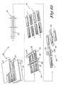
- Figure 12 represents a global survey of the method.
- a stack 27 of different layers as aforementioned, is brought into a press 19, whereby, as explained above with reference to figures 7 to 9 , boards 23 are formed which, at their surface, are provided with indentations 12.
- the component 13 is deposited in the indentations 12, which in figure 12 is indicated schematically by means of a doctor blade 24.
- the component 13 can be subjected to a drying in a forced manner, for example, by means of infrared radiation in case of thermal drying or by means of ultraviolet radiation in case of curing, for example, by means of lamps 29, which step is indicated schematically by reference 30 in figure 12 .
- the boards 23 are sawn into floor panels 1, as schematically represented in step 31, after which coupling means 7 can be formed at these floor panels 1, for example, by means of the milling cutters 33 schematically represented in step 32.
- the application of the component 13 in a suitable manner possibly may be performed in several steps. So, for example, in a first step the component 13 may be excessively provided on the respective surface by means of a roll, doctor blade or the like, whereas in a second step, the excess amount, or at least a part thereof, is removed, for example, by means of a take-up roll or wiping roll.
- the boards or panels are transported by means of a transport system along an entrained applicator roll and a removing roll rotating in countersense.
- the applicator roll preferably has a soft surface consisting, for example, of natural rubber.
- a film of liquid component 13 is provided, for example, by means of a dosage roll installed next thereto, whereby this latter is situated next to the surface of the applicator roll in such a manner that an amount of liquid component can be deposited between both rolls which is carried along at the surface of the applicator roll in the form of a film.
- the removing roll preferably has a hard smooth surface and rotates in countersense over the boards or panels.
- a chromium-plated and/or polished metal roll Preferably, to this aim use is made of a chromium-plated and/or polished metal roll.
- the component 13 which is situated out of the indentations substantially is taken along and finally removed from the removing roll by means of a doctor blade.
- a removing roll can be used which is permanently rinsed with solvent and thereby moves in countersense with a solvent film along the treated boards or panels in order to remove excess component.
- one or more removing rolls can be used.
- successively two removing rolls are used, namely a first conventional removing roll and a second, solvent-rinsed removing roll.
- Ga lamps as well as Hg lamps are applied for realizing a drying in depth as well as at the surface.
- a post-treatment may follow, whereby remaining component 13, which is present on the surface between the indentations, is wiped away dry, for example, brushed away.
- Such post-treatment is especially useful for removing a remaining tinge, formed by component 13.
- the brushing-off of said tinge may, for example, be performed by means of rotating brushes.
- brushes provided with bristles as well as with other parts with a brushing function, such as, for example, lips of abrasive paper, may be concerned.
- one or more additional measures can be taken in order to enhance the adhesion of component 13.
- One measure consists, for example, in making the upper surface of the boards or panels dust-free, for example, by means of a brushing process.
- Another measure consists, for example, in heating the upper surface of the boards or panels, such that this surface becomes somewhat softer and a better adhesion is realized.
- Still another measure consists in adapting the position of the wear-resistant particles in the top layer such that these particles, for example, corundum particles, will be situated closer to the surface than this usually is the case.
- these particles for example, corundum particles
- an improvement of the adhesion was stated which presumably is the consequence of the fact that the indentations then extend between said particles, whereby the adjoining particles then realize a better adhesion, as well as offer protection for the component 13 situated in between.
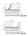
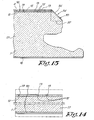
- Figure 13 illustrates that, as already described in the introduction, such floor panel 1, at one or more upper edges, in this case, the upper edge 34, can be provided with a cut-away material part, whereby the surface 35, which is created by the cutting away of this material part, is at least partially provided with a finish, in such a manner that the appearance of the surface 35 matches the effect which is obtained by the colour product applied in said indentations 12.
- this is a separate covering layer 36 provided on the surface 35, for example, by means of transfer print.
- a coating can be applied whereby the surface 35 is treated by means of a colouring substance, such as a paint, varnish, coloured impregnating agent or the like, whereby this can be provided on the surface 35 in any manner, for example, by atomising, sputtering, spraying, by means of a roll or by means of a felt-tip pencil.
- a colouring substance such as a paint, varnish, coloured impregnating agent or the like
- the surface 35 is coloured with a colouring product of the same colour, or almost the same colour, as the colouring product used for said component 13, or even component 13 itself can be used for the colouring thereof.
- the aforementioned is particularly useful in combination with floor panels 1 whereby, by the cut-away parts, a so-called "chamfer" is formed.
- the cut-away parts also may have another shape, for example, a rectangular shape, as indicated in dash-dotted line 37, for imitating a groove between the laid floor panels 1.
- the top layer 9 must not necessarily be a thermosetting resin. So, for example, the aforementioned indentations to be coloured can be provided in a transparent lacquer layer or the like, which is situated directly or indirectly above the printed decorative layer.
- indentations in said layers does not explicitly mean that these indentations thereby extend exclusively in said layer.
- the indentations may extend throughout different layers and/or create deformations therein.
- layers pressed upon each other such as the aforementioned decorative layer and overlay
- such layers during pressing, flow into each other, such that in the end product, so to speak, one layer is obtained and, thus, it becomes difficult to determine up to which layer the indentations are extending.
- the floor panel has a top layer based on synthetic material, whereby this floor panel, at its upper side, whether in said synthetic material or not, shows deepened parts, at which a component is provided which comprises an active agent.
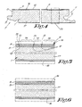
- These deepened parts may consist exclusively of indentations 12, as illustrated in figure 14 , or exclusively of surfaces 35 which are obtained by cut-away parts, for example, as illustrated in figures 15 and 16 , or also by a combination of these two possibilities.
- Another technique for providing a component 13 i.e. a colouring agent and/or active agent in indentations 12, after these indentations 12 have been formed, according to the present invention consists in that the entire surface of the boards 23, or at least major parts thereof, are covered entirely or almost entirely with the component 13 and subsequently these boards 23 are cleaned such that the component 13 substantially remains present in the indentations 12 only, whereas the component 13 situated on the intermediate parts 14 substantially is removed.
- This cleaning can be realized in different manners, for example, by wiping off, brushing or the like.
- the board 23 first can be covered with the first component, which preferably is clear transparent, with the result that the layer formed by this agent is thicker at the location of the indentations 12 than at the location of the parts 14.
- this first component can be partially evaporated, such that the thinner quantities on the parts 14 are completely or almost completely removed, whereas a certain amount of the thicker quantities at the location of the indentations 12 still remains present.
- the second component, of the resin which only reacts with the first component is applied on the board 23 and the resin is cured.
- a curing is exclusively obtained at the locations where the first as well as the second components are present, i.e. only, or almost only, in the indentations 12.
- the amount of second component which has not reacted with the first component can simply be removed by washing off, wiping off, scraping off or the like.
- a colouring product be provided at the bottom of the indentations 12, whereas thereabove a transparent layer is deposited in order to give additional characteristics to the whole.
- additional characteristics may consist, for example, in that a protective layer is formed over the colouring product or that an active component is integrated in the transparent layer.
- the invention does not exclude that component 13 is not only present in the indentations.
- the product 13 may be present on the parts 14 to a restricted extent, for example, in the form of small component residues which have remained on the surface.
- the invention relates to a "method" for imitating a coloured surface in laminate panels, more particularly for imitating coloured wood, whereby one proceeds as described in the aforegoing.
Abstract
Description
- This invention relates to a floor panel, as well as to a method for manufacturing such floor panel.
- In particular, the invention relates to so-called laminate panels for forming a floor covering.
- It is known that in such laminate panels for floors, the appearance of wood, more particularly parquetry or the like, or the appearance of stones or ceramic tiles, is imitated by providing the floor panels, in the proximity of their upper surface, with a decorative layer printed with a pattern, for example, a wood pattern or tile pattern, over which a transparent synthetic layer is provided.
- Usually, the.printed decorative layer consists of printed paper, whereas the clear synthetic layer normally consists of a synthetic resin or one or more transparent or clear resin-impregnated material layers, for example, paper layers, in which possibly also products can be incorporated in order to enlarge, for example, the wear and tear resistance of the final upper surface. Generally, said synthetic layer, at least when it also forms the top layer or, thus, uppermost layer of the floor panel, is named "overlay".
- It is also known to provide certain laminate panels with indentations and to provide an amount of paint, printing ink or the like in these indentations, in order to underline certain aspects of the pattern to be imitated.
- A known technique for realizing this is described in
DE 29 26 983 -
- Another known technique, which, amongst others, is described in
GB 2,054,458 - Other techniques are known from
JP 08-230113 JP 2002-337300 - Further, it is also known to apply techniques whereby the application of colour products on certain locations in recesses is coupled specifically to particular surface treatments, as a consequence of which the typical characteristics of the normal panel surface can not be guaranteed any longer.
- The present invention aims at a floor panel whereby, on one hand, the advantages of classical laminate panels for floors are maintained, however, on the other hand, additional components can also be incorporated in the surface in an optimum manner. Furthermore, the invention aims at a floor panel which can be realized smoothly, with minimum production costs.
- Specifically, the invention aims at a laminate panel which allows a good imitation of a patinated or coloured wooden floor.
- To this aim, the invention relates to a floor panel as defined in
claim 1. - In preferred embodiments, the invention also aims at a laminate panel, whereby one or more of the disadvantages of the above-discussed prior art are excluded.
- Other features will become clear from the appended claims and corresponding description.
- It is clear that due to the combination of the features mentioned in
claim 1, the invention allows that particularly good imitations of post-treated, in particular coloured, for example, lime-treated, wooden floor parts or parquetry parts, sometimes also called "patinated" or "cerused" floor parts or parquetry, often in short denominated with the French term "cerusé", can be realized. - An obvious solution for imitating such coloured or "patinated" floor by means of laminate panels consists in providing the decorative layer with a printed pattern representing a patinated wooden floor part or parquetry part and subsequently applying a classical overlay on top thereof. Practice has shown that in such specific application, it is difficult to arrive at a good imitation of a really coloured wooden floor.
- However, by providing the floor panels, in accordance with the present invention, on one hand, with a decorative layer printed with a wood pattern, and, on the other hand, with indentations in which a colour product is provided, a considerably better imitation can be realized. Hereby, the printed wood pattern either may consist of a traditional print, as the one applied for imitating a non-coloured floor, whereby the imitation effect of the coloration then is exclusively obtained by the colour product in the indentations, as well as of a particular print which indeed represents certain aspects of the coloration, whereby the imitation effect of the coloration then is obtained by the combination of the special print and the colour product in the indentations. According to the latter manner, by means of the print of the decorative layer at least the discoloration of a treated wood surface can be imitated, whereas by means of the colour product in the indentations, residual colour materials, which remain in the real pores or other recesses in the wood in a treatment of a real wooden floor, can be imitated.
- Preferably, in order to imitate coloured, "patinated" or lime-treated wood, said component will consist of a colour product with a light colour, in particular white. However, colour products of another colour are not excluded. These colour products as such preferably are little or not at all transparent.
- In accordance with
claim 1 said indentations are provided in function of the wood pattern, and even better follow the lines of the wood pattern. Thereby it is obtained that the pattern created by the colour product is optimally adapted to the underlying printed pattern of the decorative layer. - In a preferred embodiment the floor panel is characterized in that said component is obtained in that it has been provided in those indentations after the provision of the indentations.
- Further it is preferred that the panel comprises a top layer forming the upper surface of the floor panel, more particularly a so-called overlay, whereby this top layer, or thus, overlay is realized on the basis of a thermosetting resin, wherein said indentations are formed in said upper surface.
- As the indentations are situated in the upper side of the floor panel, and this upper side, with the exception of the indentations, remains unchanged, the floor panels will keep their classical advantages in respect to wear resistance, cleaning features and the like at their surface which is walked upon. As said component is provided in the indentations, the former is little or not at all subject to wear and tear, in particular when said indentations are realized with relatively small dimensions. Due to the fact that said component is no longer covered by an additional overlay, the clarity of the pattern or such formed by said component is not affected by an overlay.
- Preferably, the invention is applied in combination with floor panels having a top layer based on melamine resin, because such top layer as such , as is known, is very suitable for floor panels.
- It is noted that the floor panels according to the invention can be provided at one or more of their upper edges with a cut-away material part in order to create a particular profile at those edges. By means of such cut-away part, for example, a so-called "chamfer" can be formed, or simply a rectangular recess, which, when laying several floor panels adjacent to each other, forms a groove. According to a particular embodiment of the present invention, in such case the surface created by cutting away said material part is provided, at least partially, with a finish, such that the appearance of the surface is adapted to the effect obtained by the colour product in said indentations.
- Adapting the colour of the surface at the location where a part has been cut away to the colour of the applied component can be performed in any manner. To this aim, for example, a covering layer can be provided on this surface, said covering layer showing a matching colour or a matching pattern. For providing such covering layer, for example, use can be made of transfer printing, as described, amongst others, in the international patent application
WO 01/96688 - According to a particular variant, however, said surface will be coloured at least partially with a colour product having the same tint or almost the same tint as the colour product used for said component. In a particular form of embodiment, even the same agent, for example, the same paint, shall be applied to this aim. The advantage of this technique consists in that the finish of said surface, in other words, the finish of the "chamfer", automatically is adapted to the upper surface of the floor panel in an optimum manner, contrary to a coating provided by means of transfer printing, as with transfer printing, separate materials are used which then specifically must be adapted to the upper surface of the floor panel.
- According to a particular characteristic of the invention, said floor panel is provided with a coloured transparent top layer, in other words, a coloured "overlay".
- Up to the present, overlays, at least in case they are applied in combination with a printed decorative layer, always are realized such that they, after the floor panel has been formed, thus, after curing, are as transparent as possible and also as colourless as possible, in order to thereby render the printed decorative layer optimally visible. To this aim, "overlays" then are formed of an in its turn very pure paper which is impregnated with resin. The pure paper itself as such is white, however, after impregnation with resin and after pressing the overlay, it becomes almost colourless.
- By using, according to the invention, as aforementioned, a coloured "overlay", particular new effects can be realized. By a "coloured overlay", hereby an "overlay" is to be understood which, in applied condition, clearly gives the floor panel a certain tint, in other words, is not colourless. Hereby, such tint can be of any colour, including black or white.
- Basically, such tint in the top layer or, thus, overlay, can be realized by using coloured paper for the paper carrier of the overlay, however, preferably the overlay or, thus, top layer shall be coloured in that this layer is formed on the basis of coloured resin. By colouring the resin itself, on one hand, a tint is obtained, however, on the other hand, the transparency of the overlay is little or not affected.
- According to a particular form of embodiment, the coloured overlay is chosen such that, on one hand, this overlay, by means of its tint, and, on the other hand, said colour product present in the indentations, commonly contribute to a "patinating" or "colouring" effect. In such case, a classical imitated wood pattern can be used for the printed decorative layer; the coloured tint to be imitated, which is present over the entire surface, can be obtained by means of the coloured overlay; and the colour product present in the indentations can be used as an imitation of the colour product which normally in reality remains in the wood pores and the like.
- Of course, such coloured overlay also can be used for creating other particular effects.
- It is noted that the use of such coloured "overlays" allows to realize different final results, starting from one and the same printed decorative layer. In the case of the imitation of parquetry or wooden floor parts, for example, an imitation of a non-coloured floor then can be realized by means of a printed decorative layer with a clear overlay only, whereas, in case of an imitation of a coloured embodiment, one starts with one and the same printed decorative layer, which, however, in that case will be provided with a coloured overlay.
- Preferably, the coloured overlay hereby is monochromatic and thus free of any well-defined fixed pattern, with the advantage that, when forming the boards of which the floor panels are realized, the overlay must not be especially positioned in respect to the possible pattern of the printed decorative layer.
- Preferably, said indentations have a small dimension in at least one direction, more particularly a width which, for the major part of such indentations, is less than 2 mm and even better less than 1 mm. By using relatively small indentations, the component present in the indentations is not or almost not strained during the use of the floor panels.
- According to a possible embodiment, in addition to the use of a colour product, also a component is used which comprises at least one active agent. By an active agent, each product has to be understood which renders well-defined features, other than features exclusively aiming at determining the appearance or forming a top layer. To this aim, products can be applied having, for example, one or more of said features: anti-bacterial, anti-static, dirt-repellent, mildew-repellent. The application of other active agents is not excluded. Another application consists, for example, in applying materials creating a certain optical effect, such as materials having reflecting and/or fluorescent and/or phosphorescent features.
- The component in the indentations may also comprise particles which enhance wear resistance, such as corundum.
- It is clear that according to the present invention, such products can be optimally utilized in combination with floor panels, on one hand, because said component is little or not at all strained when using the floor panel and thus is very little subject to wear and tear, and, on the other hand, the respective component still can be freely present at the upper surface and consequently can be optimally active.
- It is clear that the application of an active agent as a component provided in the indentations also can be combined with the aforementioned colour product, for example, in that the active ingredients, such as anti-bacterial products, anti-static products or the like, are blended into the colour product.
- The floor panels of the invention preferably are realized as DPL (Direct Pressure Laminate).
- Said component present in the indentations preferably consists of a cured matter, such as a paint paste, a hardenable product containing active agents or the like, which matter preferably is created as a consequence of the fact that a certain amount thereof is brought into the indentations in that it is deposited therein, for example, rolled thereinto, wiped thereinto, doctored thereinto, sprayed thereinto or the like, contrary to high-pressure printing techniques.
- It is noted that the above-described possibility of imitating a post-treated wooden floor or parquetry floor, more particularly, a wooden floor or parquetry floor coloured with colour substance or the like, by means of laminate panels, according to which use is made of a decorative layer printed with a wood pattern and of indentations provided with a colour product, also can be utilized in other kinds of laminate panels, regardless whether further intermediate layers and additional covering overlays are applied, regardless of how the component is provided in the indentations, regardless of the material of which the possible overlay consists, and regardless of the fact whether an overlay is applied or not.
- It is noted that for laminate panels, the use of an active component, provided in parts which are deepened in respect to the upper surface, regardless whether those are indentations or not, and regardless of the further composition of the laminate panel, can be advantageous, as such deepened parts often allow the application of such active component in a better manner than in case such active component must be provided over the entire surface.
- As already discussed, the deepened parts to be provided with the active component may consist of indentations, preferably local indentations of small dimensions. According to another important possibility, such deepened parts are formed by the surface of parts which are formed in that at the upper side of the floor panels, whether at the edge thereof or not, material parts have been removed, for example, the surface of a so-called "chamfer", the surface of a rectangular recess, and so on.
- Also, the use of a coloured so-called overlay in combination with a printed decorative layer in its turn offers important advantages, amongst others, in that thereby a new technical structure is obtained which allows to realize new creations, more particularly patterns, appearances and the like. Also, the use of a coloured overlay offers the advantage that certain decors, the practical realization of which had been problematical before, now can be realized more adequately.
- So, for example, it is known that it is difficult to realize very light decors, for example, so-called "cérusé", as well as very dark decors in a proper manner, as with the techniques known up to now, whereby the decor is determined substantially by the printed decorative layer, the richness of the obtained decor often is considerably less than intended.
- Also, it is known that with very light or very dark decors, a large quantity of printing ink or other printing medium must be applied on the decorative layer in order to arrive at a proper appearance. On one hand, this poses the problem that such thick printing is difficult to perform. On the other hand, such thick printing results in that the decorative layer hardly takes up any resin and the necessary resin treatment or impregnation is rendered difficult. Also, this results in that more or less a layered structure is formed, as a lesser adhesion between the decorative layer and the overlay occurs, whereby, when milling the edges of the floor panels, pieces of the upper side may come off. The overlay is of course situated above the decorative layer, however, must not necessarily form the uppermost layer of the panel. In fact, it is not excluded to provide a clear colourless overlay on top of the coloured overlay.
- This technique creates new possibilities.
- One of those possibilities consists in that light or dark decors can be produced with a greater richness and with less problems by colouring the overlay with a light tint, for example, a white colour product, in the case of a light decor and colouring the overlay with a dark tint in the case of a dark decor. The inventor has found out that thereby rich decors can be realized without necessitating an extra thick print on the decorative layer, as a consequence of which the aforementioned disadvantages can be excluded.
- According to a variant of the invention, instead of the aforementioned coloured overlays, also coloured resins can be used for impregnating the decorative layer, by which similar effects as described above can be realized. Also, a combination of, on one hand, the use of a decorative layer resin-treated with a coloured resin, and, on the other hand, the use of one or more coloured overlays is possible.
- Finally, the invention also relates to a method for manufacturing a floor panel according to the invention, with the characteristic that this method comprises at least two main steps, on one hand, a first step wherein one or more basic layers, a decorative layer and a transparent so-called overlay, by means of a thermosetting synthetic material, are pressed together to a whole in a heated press, wherein, preferably simultaneously with pressing together, indentations are formed in the upper side, and on the other hand, a second step, wherein said component in the form of a colour product is brought into the indentations. This method allows for a particularly smooth production, with relatively low production costs and in a manner suitable for mass production.
- It is clear that the decorative layer and overlay possibly can be united beforehand.
- In a diverging form of embodiment of the aforementioned method, the overlay to be pressed is omitted and whether or not replaced by another layer, whereby the indentations then are formed in the resin of the resin-treated decorative layer or in said other layer.
- Generally, the invention does not exclude that apart from the described layers, additional other layers can be applied.
- With the intention of better showing the characteristics of the invention, hereafter, as an example without any limitative character, several preferred forms of embodiment are described, with reference to the accompanying drawings, wherein:
-
Figure 1 schematically represents a part of a floor covering which is composed of floor panels according to the invention; -
figure 2 represents a floor panel according to the invention in plan view; -
figures 3 and4 , at a larger scale, represent cross-sections according to lines III-III and IV-IV, respectively, infigure 2 ; -
figure 5 , at a larger scale, represents the part indicated by F5 infigure 3 ; -
figures 6 to 11 represent different steps of the method according to the invention; -
figure 12 schematically represents an entire process for realizing floor panels according to the invention;figures 13 to 16 represent a number of variants of the invention. - As represented in
figures 1 and 2 , the invention relates tofloor panels 1, more particularly laminate panels, for forming a floor covering 2. - In the represented example, the
floor panels 1 are rectangular, however, it is clear that according to variants not represented, they also can have another shape and can be, for example, square or polygonal, such as hexagonal or octagonal. - Preferably, the
floor panels 1 are provided at least at two opposite edges 3-4, and even better, as represented infigures 2 to 4 , at both pairs of edges 3-4, 5-6, respectively, with coupling means 7, by which several ofsuch floor panels 1 can be mutually coupled, such that these coupling means 7, in coupled condition, offer a locking in vertical as well as horizontal directions. - Such coupling means 7, which, as known, allow to couple the
floor panels 1 without glue, as well as uncouple them again, as such are well known from the state of the art and are described, amongst others, in the international patent applicationsWO 97/47834 WO 94/26999 floor panels 1 can be realized in different manners, for example, in such a manner thatsuch floor panels 1 can be mutually coupled by means of translation movements T1 and/or T2 and/or T3 and/or turning movements W1 and/or W2, as schematically indicated infigure 1 . - It is noted that the present invention, however, is not limited to
floor panels 1 with coupling means 7 providing in a mechanical locking in the direction R1 and R2, however, as a matter of fact also can relate tofloor panels 1 which, at one or more edges, are provided with other coupling means, for example, with a classical tongue and groove, which possibly can be glued into each other, or even can relate tofloor panels 1 comprising no coupling means at one or more edges. - As explained in the introduction and as is shown in detail in the enlarged illustration of
figure 5 , thefloor panel 1 is formed of a laminate panel comprising at least a printeddecorative layer 8, as well as atop layer 9 forming theupper surface 10 of thefloor panel 1, more particularly a so-called overlay, whereby this top layer oroverlay 9 is realized on the basis of a thermosetting resin, and this floor panel further is
characterized in that in theupper side 11 of thefloor panel 1,indentations 12 are formed and that at least in a number of theseindentations 12, acomponent 13 in the form of a colour product is provided, said component being obtained by having been deposed in theseindentations 12 after the provision of theindentations 12 themselves. - It is clear that in this manner, a
floor panel 1 is obtained of whichlarge parts 14 of theupper surface 10 still are formed by atop layer 9 which is realized on the basis of thermosetting resin, as a consequence of which the important advantages thereof are maintained, whereas, meanwhile, also saidadditional component 13 can be incorporated in the upper surface in an optimum manner, such for the purpose of realizing the effects described in the introduction. - The
top layer 9 preferably is a layer based on melamine resin, which, for example, is formed of a carrier impregnated with such resin, such as a resin-impregnated paper. - It is noted that, according to a variant of the invention, it is also possible to make no use of a separate overlay. The
top layer 9, in which the indentations are provided, then, for example, is formed by the resin with which the decorative layer itself is impregnated. - The printed
decorative layer 8 is printed with awood pattern 15, whereby this pattern then is situated at theupper side 16 of thedecorative layer 8, or at least at the upper side of the carrier of thisdecorative layer 8. - The
indentations 12 can have different forms and dimensions. Theindentations 12 are provided in function of the printedpattern 15. By "provided in function of the printedpattern 15" is meant that the form and/or dimensions and/or direction according to which theseindentations 12 extend, are adapted to the printedpattern 15. In this particular case whereby thepattern 15 consists of a wood pattern, this means that theindentations 12 follow the wood pattern, or follow it to a certain extent, as described in theWO 01/96689 indentations 12 consist of randomly provided oblong indentations which, globally, seen, extend in the longitudinal direction of the imitated wood nerves, as this traditionally is applied for laminate parquetry. - The application of
indentations 12 which are adapted to thepattern 15, in particular offers important utilization possibilities in the case that, such as claimed, theaforementioned component 13 consists of a colour product. By a "colour product", each agent is to be understood which is not colourless transparent, but results in a certain colour effect, including white or black. For such colour product, for example, use can be made of a paint, more particularly a water-based paint, or a paint in the form of an UV-hardening varnish. Also, it is not excluded to apply other substances, such as, for example, lime or the like. - As aforementioned, the aim of the claimed invention consists in imitating coloured or post-treated wooden floor parts or parquetry parts, often also called "patinated" wood or parquetry, in an efficient manner. In such case, the printed
decorative layer 8 represents awood pattern 15, whereas in theindentations 12, which are adapted to thewood pattern 15, a colour product is provided. Hereby, as schematically indicated infigure 2 , it is obtained that thewood pattern 15 is visible through the transparenttop layer 9 and possible other intermediate layers, whereas thecomponent 13, which is situated in the proximity of theupper side 11 and which, infigure 2 , is schematically indicated by a thicker kind of line, imitates a colour substance, comparable to a real colour substance, lime or such of a coloured, for example, lime-treated real wooden floor. - In the case that a lime-treated floor must be imitated, for the component 13 a colour product of a light colour, and in particular white, is applied.
- The
component 13 can also comprise an active agent in combination with said colour product. As explained in the introduction, such agent may possess, for example, anti-bacterial and/or anti-static and/or dirt-repelling and/or mildew-repelling and/or fluorescent and/or phosphorescent features. - Such products, and possible carriers to apply the former thereon, in their turn are sufficiently known from the state of the art and thus will not be described here in detail.
- In general, it is preferred that the
indentations 12, at least in one direction, show a small dimension, for example, a width which, for the majority of theindentations 12, is less than 2 mm, and even better less than 1 mm. Also, the majority of theseindentations 12 preferably is oblong, with a length varying between some millimetres and some centimetres. The depth of the indentations is random, however, of course is chosen such that no undesired damages of the surface occur during the formation thereof. - The top layer or
overlay 9 may consist of a classical colourless transparent overlay. According to a particular embodiment of the invention, however, also a coloured transparent top layer oroverlay 9 can be applied, as a consequence of which, as already explained, particular effects can be created. - In
figures 6 to 11 , schematically a method is represented for realizing afloor panel 1 according to the invention, at least for realizing the indentations and providing thecomponent 13 therein. - In the represented form of embodiment of this method, the
floor panel 1 is realized as so-called Direct Pressure Laminate (DPL). This technique allows for a smooth production, whereby in one pressing cycle, boards can be realized which already show the complete or almost complete layer structure of the end product, thus, of thefloor panels 1 to be formed. This, however, does not exclude that the invention also can be applied in combination with other techniques than those applied for manufacturing DPL. - In the method represented in the figures, first, as represented in
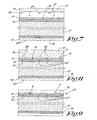
figure 6 , the different layers with which one starts, are provided on top of each other. Hereby, this relates to abasic layer 17, which in its turn may consist of several layers or composite parts or not, a printeddecorative layer 8, atop layer 9 and preferably also abacking layer 18. Thebasic layer 17 consists, for example, of a MDF/HDF board, particle board, so-called blockboard or the like. Thedecorative layer 8 may simply consist of printed paper, however, preferably has already been impregnated with resin beforehand. As aforementioned, thetop layer 9 consists of a carrier, such as a sheet of paper, impregnated with thermosetting resin. Thebacking layer 18, too, consists of a resin-impregnated carrier. - Of course, also other intermediate layers can be provided, such as, for example, additional resin-impregnated layers.
- As represented in
figure 7 , the obtained stack of layers is brought into aheated press 19, preferably a flat press, with alower plate 20 upon which the aforementioned stack is placed, and anupper plate 21, between which the whole is compressed. Theupper plate 21 is provided withprotrusions 22 or such for forming saidindentations 12. - These
indentations 12 are formed at that moment when the press, as illustrated infigure 8 , is closed, whereas the thermosetting resin of thedecorative layer 8 and thetop layer 9 melt together and harden to a whole, adhered to thebasic plate 17. - From the
press 19, acomposite board 23 is obtained as represented infigure 9 , wherein, in theupper side 11,indentations 12 are present. - Subsequently, the
component 13 is brought into these indentations. This bringing-in preferably takes place by depositing an amount of thiscomponent 13 in theindentations 12, for example, by wiping it into theindentations 12, for example, by means of doctoring, rubbing or rolling it in.Figure 10 shows howsuch component 13 can be provided in theindentations 12 by means of adoctor blade 24.Figure 11 shows a variant, whereby acomponent 13 is rolled into theindentations 12 by means of aroll 25. -
Figure 12 represents a global survey of the method. In afirst step 26, astack 27 of different layers, as aforementioned, is brought into apress 19, whereby, as explained above with reference tofigures 7 to 9 ,boards 23 are formed which, at their surface, are provided withindentations 12. In asubsequent step 28, thecomponent 13 is deposited in theindentations 12, which infigure 12 is indicated schematically by means of adoctor blade 24. Subsequently, thecomponent 13 can be subjected to a drying in a forced manner, for example, by means of infrared radiation in case of thermal drying or by means of ultraviolet radiation in case of curing, for example, by means oflamps 29, which step is indicated schematically byreference 30 infigure 12 . Subsequently, theboards 23 are sawn intofloor panels 1, as schematically represented in step 31, after which coupling means 7 can be formed at thesefloor panels 1, for example, by means of themilling cutters 33 schematically represented instep 32. - It is clear that the application of the
component 13 in a suitable manner possibly may be performed in several steps. So, for example, in a first step thecomponent 13 may be excessively provided on the respective surface by means of a roll, doctor blade or the like, whereas in a second step, the excess amount, or at least a part thereof, is removed, for example, by means of a take-up roll or wiping roll. In a practical embodiment, the boards or panels are transported by means of a transport system along an entrained applicator roll and a removing roll rotating in countersense. - The applicator roll preferably has a soft surface consisting, for example, of natural rubber. At the surface of the applicator roll, a film of
liquid component 13 is provided, for example, by means of a dosage roll installed next thereto, whereby this latter is situated next to the surface of the applicator roll in such a manner that an amount of liquid component can be deposited between both rolls which is carried along at the surface of the applicator roll in the form of a film. By the contact between the applicator roll and the boards or panels, the component is forced into the indentations, and part of it also remains present at the surface. - The removing roll preferably has a hard smooth surface and rotates in countersense over the boards or panels. Preferably, to this aim use is made of a chromium-plated and/or polished metal roll. Hereby, the
component 13 which is situated out of the indentations substantially is taken along and finally removed from the removing roll by means of a doctor blade. - Also, a removing roll can be used which is permanently rinsed with solvent and thereby moves in countersense with a solvent film along the treated boards or panels in order to remove excess component.
- It is obvious that one or more removing rolls can be used. Preferably, however, successively two removing rolls are used, namely a first conventional removing roll and a second, solvent-rinsed removing roll.
- In case that a UV drying is applied, preferably Ga lamps as well as Hg lamps are applied for realizing a drying in depth as well as at the surface.
- Also, after drying, a post-treatment may follow, whereby remaining
component 13, which is present on the surface between the indentations, is wiped away dry, for example, brushed away. Such post-treatment is especially useful for removing a remaining tinge, formed bycomponent 13. The brushing-off of said tinge may, for example, be performed by means of rotating brushes. Hereby, brushes provided with bristles as well as with other parts with a brushing function, such as, for example, lips of abrasive paper, may be concerned. - Possibly, one or more additional measures can be taken in order to enhance the adhesion of
component 13. - One measure consists, for example, in making the upper surface of the boards or panels dust-free, for example, by means of a brushing process.
- Another measure consists, for example, in heating the upper surface of the boards or panels, such that this surface becomes somewhat softer and a better adhesion is realized.
- Still another measure consists in adapting the position of the wear-resistant particles in the top layer such that these particles, for example, corundum particles, will be situated closer to the surface than this usually is the case. Hereby, an improvement of the adhesion was stated which presumably is the consequence of the fact that the indentations then extend between said particles, whereby the adjoining particles then realize a better adhesion, as well as offer protection for the
component 13 situated in between. - Hereby, it is advantageous to make use of an overlay of the type whereby the wear-resistant particles are incorporated in the paper instead of in the resin. Obviously, the particles hereby have the tendency to sit at one side of the paper. Usually, the overlay is placed with this side of the paper downward. By now applying the overlay, however, reversed, the particles will be situated closer to the upper surface, by which, as aforementioned, a better adhesion of the
component 13 is obtained. Because a film of resin is present around the paper of the overlay, the wear-resistant particles do not border the surface, as a result of which the press plates still remain more or less protected against the abrasive effect of the wear-resistant particles. -
Figure 13 illustrates that, as already described in the introduction,such floor panel 1, at one or more upper edges, in this case, theupper edge 34, can be provided with a cut-away material part, whereby thesurface 35, which is created by the cutting away of this material part, is at least partially provided with a finish, in such a manner that the appearance of thesurface 35 matches the effect which is obtained by the colour product applied in saidindentations 12. Infigure 13 , this is aseparate covering layer 36 provided on thesurface 35, for example, by means of transfer print. - According to a variant, instead of using transfer print, also a coating can be applied whereby the
surface 35 is treated by means of a colouring substance, such as a paint, varnish, coloured impregnating agent or the like, whereby this can be provided on thesurface 35 in any manner, for example, by atomising, sputtering, spraying, by means of a roll or by means of a felt-tip pencil. - Preferably, in the latter case the
surface 35 is coloured with a colouring product of the same colour, or almost the same colour, as the colouring product used for saidcomponent 13, or evencomponent 13 itself can be used for the colouring thereof. - The aforementioned is particularly useful in combination with
floor panels 1 whereby, by the cut-away parts, a so-called "chamfer" is formed. The cut-away parts, however, also may have another shape, for example, a rectangular shape, as indicated in dash-dottedline 37, for imitating a groove between the laidfloor panels 1. - The
top layer 9 must not necessarily be a thermosetting resin. So, for example, the aforementioned indentations to be coloured can be provided in a transparent lacquer layer or the like, which is situated directly or indirectly above the printed decorative layer. - Generally, it is noted that the provision of indentations in said layers does not explicitly mean that these indentations thereby extend exclusively in said layer. In fact, the indentations may extend throughout different layers and/or create deformations therein. In case of layers pressed upon each other, such as the aforementioned decorative layer and overlay, such layers, during pressing, flow into each other, such that in the end product, so to speak, one layer is obtained and, thus, it becomes difficult to determine up to which layer the indentations are extending.
- According to a particular aspect, and in combination with the main aspect of the invention, the floor panel has a top layer based on synthetic material, whereby this floor panel, at its upper side, whether in said synthetic material or not, shows deepened parts, at which a component is provided which comprises an active agent. These deepened parts may consist exclusively of
indentations 12, as illustrated infigure 14 , or exclusively ofsurfaces 35 which are obtained by cut-away parts, for example, as illustrated infigures 15 and 16 , or also by a combination of these two possibilities. - It is clear that the application of such active component in this indentations may be performed in a manner analogous to that described by means of
figures 5 to 12 . However, other techniques are not excluded. - Another technique for providing a
component 13 i.e. a colouring agent and/or active agent inindentations 12, after theseindentations 12 have been formed, according to the present invention consists in that the entire surface of theboards 23, or at least major parts thereof, are covered entirely or almost entirely with thecomponent 13 and subsequently theseboards 23 are cleaned such that thecomponent 13 substantially remains present in theindentations 12 only, whereas thecomponent 13 situated on theintermediate parts 14 substantially is removed. This cleaning can be realized in different manners, for example, by wiping off, brushing or the like. - According to a variant of this technique, one will work in at least two steps, whereby in the first step, one provides for that a first agent remains exclusively, or almost exclusively, in the
indentations 12 and subsequently, in the second step, a second agent is provided on the surface which can react and/or which properly adheres to the first agent, however, reacts little or not at all or adheres little or not at all to theparts 14 situated between theindentations 12. These technique is particularly advantageous when using two-component resins to this aim. In such case, theboard 23 first can be covered with the first component, which preferably is clear transparent, with the result that the layer formed by this agent is thicker at the location of theindentations 12 than at the location of theparts 14. Subsequently, this first component can be partially evaporated, such that the thinner quantities on theparts 14 are completely or almost completely removed, whereas a certain amount of the thicker quantities at the location of theindentations 12 still remains present. Thereafter, the second component, of the resin which only reacts with the first component, is applied on theboard 23 and the resin is cured. Hereby, a curing is exclusively obtained at the locations where the first as well as the second components are present, i.e. only, or almost only, in theindentations 12. Subsequently, the amount of second component which has not reacted with the first component can simply be removed by washing off, wiping off, scraping off or the like. - It is clear that the reacted first and second components of the two-component resin then together form the intended
component 13. - Also, it is not excluded to apply a
component 13 in theindentations 12, which component, exclusively at the location of theindentations 12, is covered with an additional layer. So, for example, may a colouring product be provided at the bottom of theindentations 12, whereas thereabove a transparent layer is deposited in order to give additional characteristics to the whole. Such additional characteristics may consist, for example, in that a protective layer is formed over the colouring product or that an active component is integrated in the transparent layer. - The invention does not exclude that
component 13 is not only present in the indentations. Theproduct 13 may be present on theparts 14 to a restricted extent, for example, in the form of small component residues which have remained on the surface. - The present invention is in no way limited to the forms of embodiment described by way of example and represented in the figures, however, such floor panel, as well as the method for manufacturing such floor panel, can be realized according to various variants, without leaving the scope of the invention.
- So, for example, it is not excluded to apply the
component 13 in the indentations after the sawing of theboards 23, and even after milling or the like, as a consequence of which the extent of the equipment required to this aim can be restricted. If this takes place after milling, or in between certain milling cycles, an already formed possible "chamfer" or, thus, bevelled edge, or another deepened part can be provided with acomponent 13 at the same time as the indentations. - By first sawing or cutting the
boards 23 into floor panels and by providing thecomponent 13 before the forming of the coupling means, it is excluded thatcomponent 13 lands onto the coupling means. - It is noted that in case that the
component 13 first is provided at the boards and only afterwards floor panels are produced thereof, it is not excluded that the boards are cut to smaller boards preceding to the application of the component. - Also, the invention relates to a "method" for imitating a coloured surface in laminate panels, more particularly for imitating coloured wood, whereby one proceeds as described in the aforegoing.
- It is clear that the invention is intended in particular for being used in combination with floor panels of the type consisting of so-called DPL (Direct Pressure Laminate).
Claims (21)
- Floor panel, of the type consisting of a laminate panel which panel comprises a decorative layer (8) which is provided with a printed pattern (15), said pattern (15) representing a wood pattern, characterized in that the floor panel (1) is provided with a coloured or "patinated" appearance, which is realized at least by the combination of, on the one hand, indentations (12) provided in the floor panel in function of the printed wood pattern, more particularly indentations which follow the lines of the wood pattern and/or represent the wood pores, and, on the other hand, a component (13) in the form of a colour product which is provided in said indentations, said component providing said colouring or patinating effect to the pattern (15) of the decorative layer (8), thereby imitating a coloured wooden surface.
- Floor panel according to claim 1, characterized in that said component (13) is obtained in that it has been provided in those indentations after the provision of the indentations.
- Floor panel according to claim 1 or 2, characterized in that the panel comprises a top layer (9) forming the upper surface (10) of the floor panel (1), more particularly a so-called overlay, whereby this top layer (9), or thus, overlay is realized on the basis of a thermosetting resin, wherein said indentations (12) are formed in said upper surface (10).
- Floor panel according to claim 3, characterized in that said top layer (9) is a layer based on melamine resin.
- Floor panel according to any of the preceding claims, characterized in that said colour product is a paint or the like.
- Floor panel according to any of the preceding claims, characterized in that by means of said component a lime-treated floor is imitated, the component being of a light colour, in particular white.
- Floor panel according to any of the preceding claims, characterized in that the floor panel (1), at least at one upper edge (34), is provided with a cut-away material part, whereby the surface (35) which is created by cutting away this material part is provided, at least partially, with a finish, as a consequence of which the appearance of the surface (35) is adapted to the effect obtained by the colour product in said indentations (12).
- Floor panel according to claim 7, characterized in that said surface (35) is coloured at least partially with a colour product of the same colour, or almost the same colour, as the colour product used for said component (13).
- Floor panel according to any of the preceding claims, characterized in that it comprises a coloured transparent overlay, which then preferably forms said top layer (9).
- Floor panel according to claim 9, characterized in that said overlay is coloured in that it is formed on the basis of coloured resin.
- Floor panel according to claim 9 or 10 characterized in that the coloured overlay, together with said colour product, commonly contribute to an imitation of a "coloured" or "patinated" floor.
- Floor panel according to any of the preceding claims, characterized in that the indentations (12) show a small dimension in at least one direction, more particularly a width which, for the major part of such indentations (12), is less than 2 mm, and even better less than 1 mm.
- Floor panel according to any of the preceding claims, characterized in that said component (13) comprises at least one active agent.
- Floor panel according to claim 13, characterized in that the active agent is a product with one or more of the following features: anti-bacterial, anti-static, dirt-repellent, mildew-repellent, fluorescent, phosphorescent.
- Floor panel according to any of the preceding claims, characterized in that it is realized as DPL (Direct Pressure Laminate).
- Floor panel according to any of the preceding claims, characterized in that said component (13) is present in the indentations (12) in the form of an amount wiped into the indentations (12) and cured, more particularly an amount which is brought into the indentations (12) in that it is rolled thereinto, wiped thereinto, doctored thereinto or the like.
- Floor panel according to any of the preceding claims, characterized in that said component (13) is situated at the location of the indentations (12), at the exterior of the floor panel (1), in other words, is not covered by means of possible further layers.
- Method for manufacturing a floor panel (1) according to any of the preceding claims, characterized in that this method comprises at least two main steps, on one hand, a first step wherein one or more basic layers, a decorative layer (8) and a transparent so-called overlay, by means of a thermosetting synthetic material, are pressed together to a whole in a heated press, whereby, simultaneously with the pressing, indentations (12) are formed in the upper side (11), and, on the other hand, a second step whereby said component (13) in the form of a colour product is brought into the indentations (12).
- Method according to claim 18, characterized in that said component (13) is brought into the indentations (12) in the form of an amount deposited therein.
- Method according to claim 18 or 19, characterized in that one starts with larger boards (23), in other words, boards (23) from which several floor panels can be manufactured; that first these boards (23) are formed and provided with indentations (12); that subsequently said component (13) is brought into the indentations (12); and that only afterwards separate floor panels are formed from the boards (23).
- Method according to claim 18 or 19, characterized in that one starts with larger boards (23), in other words, boards (23) from which several floor panels can be manufactured; that first these boards (23) are formed and provided with indentations (12); that subsequently separate floor panels are formed from the boards (23), after which a component (13), as aforementioned, is brought into the indentations (12).
Applications Claiming Priority (4)
| Application Number | Priority Date | Filing Date | Title |
|---|---|---|---|
| BE2003/0339A BE1015550A5 (en) | 2003-06-04 | 2003-06-04 | FLOOR PANEL AND METHOD FOR MANUFACTURING SUCH FLOOR PANEL. |
| US47732603P | 2003-06-11 | 2003-06-11 | |
| BE2003/0585A BE1015760A6 (en) | 2003-06-04 | 2003-10-31 | Laminated floorboard has a decorative overlay and color product components inserted into recesses which, together, give a variety of visual wood effects |
| PCT/EP2004/006082 WO2004108436A2 (en) | 2003-06-04 | 2004-06-02 | Floor panel and method for manufacturing such floor panel |
Publications (2)
| Publication Number | Publication Date |
|---|---|
| EP1628839A2 EP1628839A2 (en) | 2006-03-01 |
| EP1628839B1 true EP1628839B1 (en) | 2009-07-01 |
Family
ID=34862390
Family Applications (1)
| Application Number | Title | Priority Date | Filing Date |
|---|---|---|---|
| EP04735744A Not-in-force EP1628839B1 (en) | 2003-06-04 | 2004-06-02 | Floor panel and method for manufacturing such floor panel |
Country Status (7)
| Country | Link |
|---|---|
| US (1) | US20040255541A1 (en) |
| EP (1) | EP1628839B1 (en) |
| AT (1) | ATE435127T1 (en) |
| BE (1) | BE1015760A6 (en) |
| DE (1) | DE602004021800D1 (en) |
| ES (1) | ES2328143T3 (en) |
| WO (1) | WO2004108436A2 (en) |
Families Citing this family (112)
| Publication number | Priority date | Publication date | Assignee | Title |
|---|---|---|---|---|
| US20020178674A1 (en) | 1993-05-10 | 2002-12-05 | Tony Pervan | System for joining a building board |
| US7121059B2 (en) * | 1994-04-29 | 2006-10-17 | Valinge Innovation Ab | System for joining building panels |
| SE517183C2 (en) | 2000-01-24 | 2002-04-23 | Valinge Aluminium Ab | Locking system for mechanical joining of floorboards, floorboard provided with the locking system and method for making such floorboards |
| US6851241B2 (en) * | 2001-01-12 | 2005-02-08 | Valinge Aluminium Ab | Floorboards and methods for production and installation thereof |
| US8028486B2 (en) | 2001-07-27 | 2011-10-04 | Valinge Innovation Ab | Floor panel with sealing means |
| SE525558C2 (en) * | 2001-09-20 | 2005-03-08 | Vaelinge Innovation Ab | System for forming a floor covering, set of floorboards and method for manufacturing two different types of floorboards |
| US8250825B2 (en) | 2001-09-20 | 2012-08-28 | Välinge Innovation AB | Flooring and method for laying and manufacturing the same |
| SE525661C2 (en) | 2002-03-20 | 2005-03-29 | Vaelinge Innovation Ab | Floor boards decorative joint portion making system, has surface layer with underlying layer such that adjoining edge with surface has underlying layer parallel to horizontal plane |
| BRPI0308966B8 (en) | 2002-04-03 | 2016-05-17 | Vaelinge Innovation Ab | floor board |
| SE525657C2 (en) | 2002-04-08 | 2005-03-29 | Vaelinge Innovation Ab | Flooring boards for floating floors made of at least two different layers of material and semi-finished products for the manufacture of floorboards |
| US8850769B2 (en) | 2002-04-15 | 2014-10-07 | Valinge Innovation Ab | Floorboards for floating floors |
| US7051486B2 (en) * | 2002-04-15 | 2006-05-30 | Valinge Aluminium Ab | Mechanical locking system for floating floor |
| US7617651B2 (en) | 2002-11-12 | 2009-11-17 | Kronotec Ag | Floor panel |
| DE10262235B4 (en) | 2002-11-12 | 2010-05-12 | Kronotec Ag | Particle board, in particular floor panel or furniture panel, and method for its production |
| ATE395481T1 (en) | 2002-11-15 | 2008-05-15 | Flooring Technologies Ltd | DEVICE CONSISTS OF TWO BUILDING PLATES THAT CAN BE CONNECTED TO EACH OTHER AND AN INSERT FOR LOCKING THESE BUILDING PLATES |
| DE10306118A1 (en) | 2003-02-14 | 2004-09-09 | Kronotec Ag | building board |
| US20040206036A1 (en) | 2003-02-24 | 2004-10-21 | Valinge Aluminium Ab | Floorboard and method for manufacturing thereof |
| US7845140B2 (en) | 2003-03-06 | 2010-12-07 | Valinge Innovation Ab | Flooring and method for installation and manufacturing thereof |
| US7677001B2 (en) | 2003-03-06 | 2010-03-16 | Valinge Innovation Ab | Flooring systems and methods for installation |
| US7678425B2 (en) | 2003-03-06 | 2010-03-16 | Flooring Technologies Ltd. | Process for finishing a wooden board and wooden board produced by the process |
| DE20304761U1 (en) | 2003-03-24 | 2004-04-08 | Kronotec Ag | Device for connecting building boards, in particular floor panels |
| DE10341172B4 (en) | 2003-09-06 | 2009-07-23 | Kronotec Ag | Method for sealing a building board |
| US7640664B1 (en) * | 2003-09-15 | 2010-01-05 | Potlach Corporation | Process for manufacturing wood-based composite panel with reduced top surface edge flare |
| DE20315676U1 (en) | 2003-10-11 | 2003-12-11 | Kronotec Ag | Panel, especially floor panel |
| US7886497B2 (en) | 2003-12-02 | 2011-02-15 | Valinge Innovation Ab | Floorboard, system and method for forming a flooring, and a flooring formed thereof |
| BE1015825A5 (en) | 2003-12-18 | 2005-09-06 | Flooring Ind Ltd | Plinth, FLOORING SYSTEM AND METHOD FOR MANUFACTURING A Plinth. |
| SE526596C2 (en) * | 2004-01-13 | 2005-10-11 | Vaelinge Innovation Ab | Floating floor with mechanical locking system that allows movement between the floorboards |
| US20050166516A1 (en) | 2004-01-13 | 2005-08-04 | Valinge Aluminium Ab | Floor covering and locking systems |
| US7516588B2 (en) * | 2004-01-13 | 2009-04-14 | Valinge Aluminium Ab | Floor covering and locking systems |
| DE202004001037U1 (en) * | 2004-01-24 | 2004-04-29 | Kronotec Ag | Panel, in particular floor panel |
| DE102004011931B4 (en) | 2004-03-11 | 2006-09-14 | Kronotec Ag | Insulation board made of a wood-material-binder fiber mixture |
| US20060024465A1 (en) * | 2004-07-30 | 2006-02-02 | Jean Briere | Laminate flooring members |
| SE527570C2 (en) | 2004-10-05 | 2006-04-11 | Vaelinge Innovation Ab | Device and method for surface treatment of sheet-shaped material and floor board |
| US7841144B2 (en) | 2005-03-30 | 2010-11-30 | Valinge Innovation Ab | Mechanical locking system for panels and method of installing same |
| US7454875B2 (en) | 2004-10-22 | 2008-11-25 | Valinge Aluminium Ab | Mechanical locking system for floor panels |
| EP2050582B1 (en) * | 2004-12-16 | 2013-03-06 | Flooring Industries Ltd. | Floor panel having zones of different gloss degrees |
| PL1711353T3 (en) | 2004-12-23 | 2010-05-31 | Flooring Ind Ltd | Laminate floor panel |
| US20060144004A1 (en) * | 2005-01-06 | 2006-07-06 | Oke Nollet | Floor panel and method for manufacturing a floor panel |
| DE102005001629A1 (en) * | 2005-01-12 | 2006-07-20 | Akzenta Paneele + Profile Gmbh | floor panel |
| DE102005002295A1 (en) * | 2005-01-17 | 2006-07-27 | Kaindl Flooring Gmbh | Panels with long plank look |
| US8215078B2 (en) | 2005-02-15 | 2012-07-10 | Välinge Innovation Belgium BVBA | Building panel with compressed edges and method of making same |
| BE1016464A3 (en) | 2005-02-23 | 2006-11-07 | Flooring Ind Ltd | Manufacture of laminate floor panels used in forming floating floor covering, involves forming floor panels at least partially using laser treatment of board-shaped material |
| US8061104B2 (en) | 2005-05-20 | 2011-11-22 | Valinge Innovation Ab | Mechanical locking system for floor panels |
| EP1760197A3 (en) * | 2005-08-17 | 2007-03-14 | Umformtechnik GmbH | Shaped or decorative elements made of metal |
| US7854986B2 (en) * | 2005-09-08 | 2010-12-21 | Flooring Technologies Ltd. | Building board and method for production |
| DE102005042658B3 (en) | 2005-09-08 | 2007-03-01 | Kronotec Ag | Tongued and grooved board for flooring has at least one side surface and tongue and/or groove with decorative layer applied |
| DE102005042657B4 (en) † | 2005-09-08 | 2010-12-30 | Kronotec Ag | Building board and method of manufacture |
| US20070068110A1 (en) * | 2005-09-28 | 2007-03-29 | Bing-Hong Liu | Floor panel with coupling means and methods of making the same |
| BE1016846A3 (en) | 2005-11-09 | 2007-08-07 | Flooring Ind Ltd | Floor covering has hard floor panels having at least one chamfer having surface covered with separate decorative covering by transfer printing technique |
| BE1016875A5 (en) | 2005-12-23 | 2007-08-07 | Flooring Ind Ltd | FLOOR PANEL AND METHOD FOR MANUFACTURING SUCH FLOOR PANEL. |
| DE102005063034B4 (en) | 2005-12-29 | 2007-10-31 | Flooring Technologies Ltd. | Panel, in particular floor panel |
| US20070175144A1 (en) * | 2006-01-11 | 2007-08-02 | Valinge Innovation Ab | V-groove |
| SE530653C2 (en) | 2006-01-12 | 2008-07-29 | Vaelinge Innovation Ab | Moisture-proof floor board and floor with an elastic surface layer including a decorative groove |
| DE102006007976B4 (en) | 2006-02-21 | 2007-11-08 | Flooring Technologies Ltd. | Process for refining a building board |
| SE0600680L (en) * | 2006-03-27 | 2006-12-19 | Tarkett Ab | Ways to make a floorboard |
| BE1017049A6 (en) * | 2006-04-06 | 2007-12-04 | Flooring Ind Ltd | METHOD FOR MANUFACTURING FLOOR PANELS AND FLOOR PANEL. |
| US7918062B2 (en) | 2006-06-08 | 2011-04-05 | Mannington Mills, Inc. | Methods and systems for decorating bevel and other surfaces of laminated floorings |
| SE533410C2 (en) | 2006-07-11 | 2010-09-14 | Vaelinge Innovation Ab | Floor panels with mechanical locking systems with a flexible and slidable tongue as well as heavy therefore |
| US8323016B2 (en) * | 2006-09-15 | 2012-12-04 | Valinge Innovation Belgium Bvba | Device and method for compressing an edge of a building panel and a building panel with compressed edges |
| US20080236431A1 (en) | 2007-03-28 | 2008-10-02 | Pergo (Europe) Ab | Process for Color Variability in Printing to Simulate Color Variation of Natural Product |
| BE1017703A6 (en) | 2007-07-26 | 2009-04-07 | Flooring Ind Ltd | METHODS FOR MANUFACTURING PANELS AND PANEL. |
| EP2250033A2 (en) | 2008-01-09 | 2010-11-17 | Flooring Industries Limited, SARL | Panels and method for manufacturing |
| ATE552990T1 (en) | 2008-04-29 | 2012-04-15 | Flooring Ind Ltd Sarl | FLOOR PANEL, METHOD FOR PRODUCING FLOOR PANELS AND TRANSFER FILM |
| BE1018177A3 (en) * | 2008-06-10 | 2010-06-01 | Flooring Ind Ltd Sarl | PRINTED SUBSTRATE, METHOD FOR MANUFACTURING FLOOR PANELS AND METHOD FOR MANUFACTURING PRINTED SUBSTRATES. |
| FR2934520A1 (en) * | 2008-08-04 | 2010-02-05 | Adhetec | Insert inlaying method for plastic floor covering of e.g. railroad car, involves forming housing on upper face of floor covering sheet, where depth of housing is less than thickness of sheet to permit intactness of lower face of sheet |
| EP2221190A1 (en) * | 2009-02-23 | 2010-08-25 | Tarkett GDL | Flooring |
| US8365499B2 (en) | 2009-09-04 | 2013-02-05 | Valinge Innovation Ab | Resilient floor |
| US11725395B2 (en) | 2009-09-04 | 2023-08-15 | Välinge Innovation AB | Resilient floor |
| EP2513386B1 (en) | 2009-12-17 | 2019-11-06 | Välinge Innovation AB | Method and arrangements relating to surface forming of building panels |
| US8833028B2 (en) | 2010-01-11 | 2014-09-16 | Valinge Innovation Ab | Floor covering with interlocking design |
| US9079326B2 (en) | 2010-03-15 | 2015-07-14 | Ainsworth Lumber Co. Ltd. | Profiling saw blade and method of using |
| DE212010000195U1 (en) | 2010-04-15 | 2012-08-06 | Spanolux N.V. Div. Balterio | Bottom plate arrangement |
| UA109938C2 (en) | 2011-05-06 | 2015-10-26 | MECHANICAL LOCKING SYSTEM FOR CONSTRUCTION PANELS | |
| UA114715C2 (en) | 2011-07-05 | 2017-07-25 | Сералок Інновейшн Аб | Mechanical locking of floor panels with a glued tongue |
| US9725912B2 (en) | 2011-07-11 | 2017-08-08 | Ceraloc Innovation Ab | Mechanical locking system for floor panels |
| US8650826B2 (en) | 2011-07-19 | 2014-02-18 | Valinge Flooring Technology Ab | Mechanical locking system for floor panels |
| US8769905B2 (en) | 2011-08-15 | 2014-07-08 | Valinge Flooring Technology Ab | Mechanical locking system for floor panels |
| US8857126B2 (en) | 2011-08-15 | 2014-10-14 | Valinge Flooring Technology Ab | Mechanical locking system for floor panels |
| US8763340B2 (en) | 2011-08-15 | 2014-07-01 | Valinge Flooring Technology Ab | Mechanical locking system for floor panels |
| RU2672903C2 (en) | 2011-08-29 | 2018-11-20 | Сералок Инновейшн Аб | Mechanical locking system for floor panels |
| US8596013B2 (en) | 2012-04-04 | 2013-12-03 | Valinge Innovation Ab | Building panel with a mechanical locking system |
| US9216541B2 (en) | 2012-04-04 | 2015-12-22 | Valinge Innovation Ab | Method for producing a mechanical locking system for building panels |
| ES2661954T3 (en) | 2012-11-07 | 2018-04-04 | Akzenta Paneele + Profile Gmbh | Procedure for the manufacture of a decorated wall or floor panel |
| ES2673421T3 (en) * | 2013-03-25 | 2018-06-21 | Välinge Innovation AB | Floor boards provided with a mechanical locking system and method to produce such locking system |
| DE102013113125A1 (en) | 2013-11-27 | 2015-05-28 | Guido Schulte | Floor, wall or ceiling panel and method of making the same |
| DE102013113130B4 (en) | 2013-11-27 | 2022-01-27 | Välinge Innovation AB | Method of manufacturing a floorboard |
| DE102013113109A1 (en) | 2013-11-27 | 2015-06-11 | Guido Schulte | floorboard |
| HRP20231029T1 (en) | 2014-01-10 | 2023-12-22 | Välinge Innovation AB | Wood fibre based panel with a surface layer |
| EP2910708A1 (en) * | 2014-02-25 | 2015-08-26 | Tarkett GDL S.A. | Synthetic floor coverings with colored overlay |
| KR102398462B1 (en) | 2014-03-24 | 2022-05-13 | 플로어링 인더스트리즈 리미티드 에스에이알엘 | A set of mutually lockable panels |
| US9260870B2 (en) | 2014-03-24 | 2016-02-16 | Ivc N.V. | Set of mutually lockable panels |
| CH709448A1 (en) * | 2014-03-31 | 2015-10-15 | Proverum Ag | A method for processing a useful surface of a floor covering. |
| ES2960221T3 (en) | 2014-07-16 | 2024-03-01 | Vaelinge Innovation Ab | Method for producing a thermoplastic wear-resistant sheet |
| EP3567184B1 (en) | 2014-08-29 | 2022-12-28 | Välinge Innovation AB | Vertical joint system for a surface covering panel |
| EP3310580A4 (en) | 2015-06-16 | 2019-02-13 | Välinge Innovation AB | A method of forming a building panel or surface element and such a building panel and surface element |
| CN108368704A (en) | 2015-12-17 | 2018-08-03 | 瓦林格创新股份有限公司 | Method for manufacturing the mechanical locking system for being used for panelling |
| PL3448674T3 (en) | 2016-04-25 | 2021-08-02 | Välinge Innovation AB | A veneered element and method of producing such a veneered element |
| MX2019003403A (en) | 2016-09-30 | 2019-05-30 | Vaelinge Innovation Ab | Set of panels assembled by vertical displacement and locked together in the vertical and horizontal direction. |
| EA201992222A1 (en) | 2017-09-28 | 2020-02-10 | Юнилин, Бвба | PLATE AND METHOD FOR MAKING A PLATE |
| EP3737802B1 (en) | 2018-01-09 | 2023-05-10 | Välinge Innovation AB | Set of panels |
| WO2019139519A1 (en) | 2018-01-10 | 2019-07-18 | Välinge Innovation AB | Subfloor joint |
| PL3737559T3 (en) | 2018-01-11 | 2024-01-22 | Välinge Innovation AB | A method to produce a veneered element and a veneered element |
| WO2019139523A1 (en) | 2018-01-11 | 2019-07-18 | Välinge Innovation AB | A method to produce a veneered element and a veneered element |
| PL3517313T3 (en) * | 2018-01-26 | 2020-10-19 | SWISS KRONO Tec AG | Subsequent changing of a decorative surface |
| WO2019226041A1 (en) * | 2018-05-21 | 2019-11-28 | 5R Technologies Sdn. Bhd. | A natural effect panel and method of fabricating the same |
| WO2020117117A1 (en) | 2018-12-05 | 2020-06-11 | Välinge Innovation AB | Subfloor joint |
| WO2020145870A1 (en) | 2019-01-09 | 2020-07-16 | Välinge Innovation AB | A method to produce a veneer element and a veneer element |
| US10677275B1 (en) * | 2019-02-18 | 2020-06-09 | Daltile Corporation | Floor element for forming a floor covering, a floor covering and a method for manufacturing a floor element |
| PT3708739T (en) * | 2019-03-12 | 2021-05-17 | Flooring Technologies Ltd | Hard floor panel for floating installation forming a floor |
| US11339576B2 (en) | 2019-09-17 | 2022-05-24 | Daltile Corporation | Floor element for forming a floor covering and a floor covering |
| US11559961B2 (en) | 2019-09-17 | 2023-01-24 | Daltile Corporation | Pressing equipment, a plant and a method for forming a floor element |
| CN110696516A (en) * | 2019-10-12 | 2020-01-17 | 浙江晶通塑胶有限公司 | Processing technology of digital printing floor |
Family Cites Families (43)
| Publication number | Priority date | Publication date | Assignee | Title |
|---|---|---|---|---|
| US1551544A (en) * | 1925-09-01 | Flooring | ||
| US110669A (en) * | 1871-01-03 | Improvement in sewing-machines for working button-holes | ||
| US444042A (en) * | 1890-04-03 | 1891-01-06 | Veneered lumber | |
| US2016567A (en) * | 1931-03-09 | 1935-10-08 | Woodall Industries Inc | Fabrication of composition fiber board |
| US2226540A (en) * | 1940-07-16 | 1940-12-31 | William A F Boettcher | Floor block |
| US2328051A (en) * | 1940-08-21 | 1943-08-31 | Minnesota & Ontario Paper Co | Wall construction |
| US3204380A (en) * | 1962-01-31 | 1965-09-07 | Allied Chem | Acoustical tiles with thermoplastic covering sheets and interlocking tongue-and-groove edge connections |
| DE2108141A1 (en) * | 1970-02-20 | 1971-09-30 | Bruun & Soerensen A/S, Aarhus (Dänemark) | Floor construction |
| US3814647A (en) * | 1972-05-24 | 1974-06-04 | Exxon Research Engineering Co | High pressure decorative laminate with ink surface registered with embossing |
| US3936541A (en) * | 1973-12-26 | 1976-02-03 | Abitibi Corporation | Surface decoration of embossed or textured panel products |
| US4284453A (en) * | 1978-01-11 | 1981-08-18 | Consolidated Papers, Inc. | Method of imparting color highlights or shadows to a textured decorative laminate |
| AU534456B2 (en) * | 1979-07-02 | 1984-02-02 | Toppan Printing Co. Ltd. | Decorate laminates |
| DE2926983A1 (en) * | 1979-07-04 | 1981-01-22 | Roemmler H Resopal Werk Gmbh | Decorative laminated plate prodn. method - includes pressing operation which only partly hardens supporting layer |
| US4237087A (en) * | 1979-10-05 | 1980-12-02 | Armstrong Cork Company | Method of embossing wood composition board |
| US4953335A (en) * | 1988-04-26 | 1990-09-04 | Eidai Industry Co., Ltd. | Decorative board having hot-melt resin joints |
| WO1992013151A1 (en) * | 1991-01-22 | 1992-08-06 | Arnes Plåt Ab | Building element |
| US5744220A (en) * | 1991-07-02 | 1998-04-28 | Perstorp Ab | Thermosetting laminate |
| US5834081A (en) * | 1991-12-30 | 1998-11-10 | The Amtico Company Limited | Tiles, method of manufacturing tiles from plastic material and equipment for facilitating such manufacture |
| SE9301595L (en) * | 1993-05-10 | 1994-10-17 | Tony Pervan | Grout for thin liquid hard floors |
| US5570554A (en) * | 1994-05-16 | 1996-11-05 | Fas Industries, Inc. | Interlocking stapled flooring |
| US5587218A (en) * | 1994-05-18 | 1996-12-24 | Betz; Richard T. | Surface covering |
| JPH081895A (en) * | 1994-06-21 | 1996-01-09 | Dainippon Printing Co Ltd | Decorative sheet and production thereof |
| US5502939A (en) * | 1994-07-28 | 1996-04-02 | Elite Panel Products | Interlocking panels having flats for increased versatility |
| JP3185590B2 (en) * | 1995-02-28 | 2001-07-11 | 凸版印刷株式会社 | Decorative sheet and method for producing the same |
| US5618602A (en) * | 1995-03-22 | 1997-04-08 | Wilsonart Int Inc | Articles with tongue and groove joint and method of making such a joint |
| US5891564A (en) * | 1995-06-07 | 1999-04-06 | Mannington Mills, Inc. | Decorative surface coverings |
| EP0852251B1 (en) * | 1995-09-22 | 2003-05-28 | Daikin Industries, Limited | Stain-proofing agent for preventing adherence of stain and composition for paints |
| US5755068A (en) * | 1995-11-17 | 1998-05-26 | Ormiston; Fred I. | Veneer panels and method of making |
| BE1010487A6 (en) * | 1996-06-11 | 1998-10-06 | Unilin Beheer Bv | FLOOR COATING CONSISTING OF HARD FLOOR PANELS AND METHOD FOR MANUFACTURING SUCH FLOOR PANELS. |
| US6131355A (en) * | 1996-11-21 | 2000-10-17 | Crane Plastics Company Limited Partnership | Deck plank |
| US5797237A (en) * | 1997-02-28 | 1998-08-25 | Standard Plywoods, Incorporated | Flooring system |
| US6324809B1 (en) * | 1997-11-25 | 2001-12-04 | Premark Rwp Holdings, Inc. | Article with interlocking edges and covering product prepared therefrom |
| US6150009A (en) * | 1998-08-07 | 2000-11-21 | Surface Technologies, Inc. | Decorative structural panel |
| ES2168045B2 (en) * | 1999-11-05 | 2004-01-01 | Ind Aux Es Faus Sl | NEW DIRECT LAMINATED FLOOR. |
| US7169460B1 (en) * | 1999-12-14 | 2007-01-30 | Mannington Mills, Inc. | Thermoplastic planks and methods for making the same |
| US6617009B1 (en) * | 1999-12-14 | 2003-09-09 | Mannington Mills, Inc. | Thermoplastic planks and methods for making the same |
| SE516696C2 (en) * | 1999-12-23 | 2002-02-12 | Perstorp Flooring Ab | Process for producing surface elements comprising an upper decorative layer as well as surface elements produced according to the method |
| US6332733B1 (en) * | 1999-12-23 | 2001-12-25 | Hamberger Industriewerke Gmbh | Joint |
| US6363677B1 (en) * | 2000-04-10 | 2002-04-02 | Mannington Mills, Inc. | Surface covering system and methods of installing same |
| US6581351B2 (en) * | 2000-05-02 | 2003-06-24 | Devivi David C. | Flooring |
| PT1676720E (en) * | 2000-06-13 | 2011-02-28 | Flooring Ind Ltd | Floor covering |
| JP2002337300A (en) * | 2001-05-18 | 2002-11-27 | Yamaha Livingtec Corp | Woodgrain decorative panel and method for manufacturing the same |
| US6945007B2 (en) * | 2001-08-21 | 2005-09-20 | Milliken & Company | Method of patterning, installing, renewing and/or recycling carpet tiles |
-
2003
- 2003-10-31 BE BE2003/0585A patent/BE1015760A6/en not_active IP Right Cessation
-
2004
- 2004-06-02 DE DE602004021800T patent/DE602004021800D1/en active Active
- 2004-06-02 EP EP04735744A patent/EP1628839B1/en not_active Not-in-force
- 2004-06-02 ES ES04735744T patent/ES2328143T3/en active Active
- 2004-06-02 WO PCT/EP2004/006082 patent/WO2004108436A2/en active Application Filing
- 2004-06-02 AT AT04735744T patent/ATE435127T1/en not_active IP Right Cessation
- 2004-06-14 US US10/866,342 patent/US20040255541A1/en not_active Abandoned
Also Published As
| Publication number | Publication date |
|---|---|
| WO2004108436A2 (en) | 2004-12-16 |
| BE1015760A6 (en) | 2005-08-02 |
| ATE435127T1 (en) | 2009-07-15 |
| EP1628839A2 (en) | 2006-03-01 |
| US20040255541A1 (en) | 2004-12-23 |
| ES2328143T3 (en) | 2009-11-10 |
| DE602004021800D1 (en) | 2009-08-13 |
| WO2004108436A3 (en) | 2005-02-10 |
Similar Documents
| Publication | Publication Date | Title |
|---|---|---|
| EP1628839B1 (en) | Floor panel and method for manufacturing such floor panel | |
| US9506256B2 (en) | Floor covering, floor panels and method for manufacturing floor panels | |
| US8919063B2 (en) | Building board having a pattern applied onto side surfaces and conecting mechanisms thereof | |
| RU2526009C2 (en) | Production of floor panel and floor panel thus made | |
| EP3351375B1 (en) | Fibre based panels with a decorative wear resistance surface | |
| US20040086678A1 (en) | Surface covering panel | |
| ES2357639T3 (en) | WOOD COMPOSITE BOARD WITH AUTHENTIC WOOD PLUG AND PROCEDURE TO IMPROVE YOUR FINISH. | |
| CN102140835A (en) | Direct printed lightweight panel | |
| CN107530734A (en) | The method on manufacturing structured surface and the product of such structuring | |
| US8003168B2 (en) | Method for sealing a building panel | |
| US8173240B2 (en) | Decorative paper with sprinkled corundum, coated with an adhesive | |
| NL2025115B1 (en) | Decorative surface covering element, surface covering element covering, and method of producing such a decorative surface covering element | |
| US20060188757A1 (en) | Simulated decorative surface | |
| KR20120098150A (en) | Floor board and manufacturing method thereof | |
| JP2007031995A (en) | Woody floor material | |
| JP4775271B2 (en) | Makeup Particleboard Manufacturing Method and Makeup Particleboard | |
| RU2773461C2 (en) | Subsequent modification of decorative surface | |
| KR101815714B1 (en) | Floor board and manufacturing method thereof | |
| WO2021118404A1 (en) | Method for producing an artistic decorative coating on the surface of flat cork panels | |
| WO2021156280A1 (en) | Method for the manufacture of a floor plank with a wood based substrate | |
| JPS6113872B2 (en) | ||
| RU2498908C2 (en) | Building board and method of its making | |
| WO2019145443A1 (en) | Subsequent altering of a decorative surface | |
| JPH0130485Y2 (en) | ||
| JPH0827990A (en) | Decorative sheet and its manufacture |
Legal Events
| Date | Code | Title | Description |
|---|---|---|---|
| PUAI | Public reference made under article 153(3) epc to a published international application that has entered the european phase |
Free format text: ORIGINAL CODE: 0009012 |
|
| 17P | Request for examination filed |
Effective date: 20050922 |
|
| AK | Designated contracting states |
Kind code of ref document: A2 Designated state(s): AT BE BG CH CY CZ DE DK EE ES FI FR GB GR HU IE IT LI LU MC NL PL PT RO SE SI SK TR |
|
| DAX | Request for extension of the european patent (deleted) | ||
| 17Q | First examination report despatched |
Effective date: 20061011 |
|
| 17Q | First examination report despatched |
Effective date: 20061011 |
|
| RIN1 | Information on inventor provided before grant (corrected) |
Inventor name: VANHASTEL, LUC, DIRK, DANI??L Inventor name: THIERS, BERNARD, PAUL, JOSEPH Inventor name: DE BOE, LODE, HUBERT, LIEVEN |
|
| GRAP | Despatch of communication of intention to grant a patent |
Free format text: ORIGINAL CODE: EPIDOSNIGR1 |
|
| GRAS | Grant fee paid |
Free format text: ORIGINAL CODE: EPIDOSNIGR3 |
|
| GRAA | (expected) grant |
Free format text: ORIGINAL CODE: 0009210 |
|
| AK | Designated contracting states |
Kind code of ref document: B1 Designated state(s): AT BE BG CH CY CZ DE DK EE ES FI FR GB GR HU IE IT LI LU MC NL PL PT RO SE SI SK TR |
|
| REG | Reference to a national code |
Ref country code: GB Ref legal event code: FG4D |
|
| REG | Reference to a national code |
Ref country code: CH Ref legal event code: EP |
|
| REG | Reference to a national code |
Ref country code: IE Ref legal event code: FG4D |
|
| REF | Corresponds to: |
Ref document number: 602004021800 Country of ref document: DE Date of ref document: 20090813 Kind code of ref document: P |
|
| REG | Reference to a national code |
Ref country code: ES Ref legal event code: FG2A Ref document number: 2328143 Country of ref document: ES Kind code of ref document: T3 |
|
| PG25 | Lapsed in a contracting state [announced via postgrant information from national office to epo] |
Ref country code: SI Free format text: LAPSE BECAUSE OF FAILURE TO SUBMIT A TRANSLATION OF THE DESCRIPTION OR TO PAY THE FEE WITHIN THE PRESCRIBED TIME-LIMIT Effective date: 20090701 |
|
| PG25 | Lapsed in a contracting state [announced via postgrant information from national office to epo] |
Ref country code: EE Free format text: LAPSE BECAUSE OF FAILURE TO SUBMIT A TRANSLATION OF THE DESCRIPTION OR TO PAY THE FEE WITHIN THE PRESCRIBED TIME-LIMIT Effective date: 20090701 Ref country code: FI Free format text: LAPSE BECAUSE OF FAILURE TO SUBMIT A TRANSLATION OF THE DESCRIPTION OR TO PAY THE FEE WITHIN THE PRESCRIBED TIME-LIMIT Effective date: 20090701 Ref country code: SE Free format text: LAPSE BECAUSE OF FAILURE TO SUBMIT A TRANSLATION OF THE DESCRIPTION OR TO PAY THE FEE WITHIN THE PRESCRIBED TIME-LIMIT Effective date: 20090701 Ref country code: AT Free format text: LAPSE BECAUSE OF FAILURE TO SUBMIT A TRANSLATION OF THE DESCRIPTION OR TO PAY THE FEE WITHIN THE PRESCRIBED TIME-LIMIT Effective date: 20090701 |
|
| PG25 | Lapsed in a contracting state [announced via postgrant information from national office to epo] |
Ref country code: PL Free format text: LAPSE BECAUSE OF FAILURE TO SUBMIT A TRANSLATION OF THE DESCRIPTION OR TO PAY THE FEE WITHIN THE PRESCRIBED TIME-LIMIT Effective date: 20090701 |
|
| PG25 | Lapsed in a contracting state [announced via postgrant information from national office to epo] |
Ref country code: PT Free format text: LAPSE BECAUSE OF FAILURE TO SUBMIT A TRANSLATION OF THE DESCRIPTION OR TO PAY THE FEE WITHIN THE PRESCRIBED TIME-LIMIT Effective date: 20091102 Ref country code: BG Free format text: LAPSE BECAUSE OF FAILURE TO SUBMIT A TRANSLATION OF THE DESCRIPTION OR TO PAY THE FEE WITHIN THE PRESCRIBED TIME-LIMIT Effective date: 20091001 |
|
| PG25 | Lapsed in a contracting state [announced via postgrant information from national office to epo] |
Ref country code: RO Free format text: LAPSE BECAUSE OF FAILURE TO SUBMIT A TRANSLATION OF THE DESCRIPTION OR TO PAY THE FEE WITHIN THE PRESCRIBED TIME-LIMIT Effective date: 20090701 Ref country code: DK Free format text: LAPSE BECAUSE OF FAILURE TO SUBMIT A TRANSLATION OF THE DESCRIPTION OR TO PAY THE FEE WITHIN THE PRESCRIBED TIME-LIMIT Effective date: 20090701 Ref country code: CZ Free format text: LAPSE BECAUSE OF FAILURE TO SUBMIT A TRANSLATION OF THE DESCRIPTION OR TO PAY THE FEE WITHIN THE PRESCRIBED TIME-LIMIT Effective date: 20090701 |
|
| PLBE | No opposition filed within time limit |
Free format text: ORIGINAL CODE: 0009261 |
|
| STAA | Information on the status of an ep patent application or granted ep patent |
Free format text: STATUS: NO OPPOSITION FILED WITHIN TIME LIMIT |
|
| PG25 | Lapsed in a contracting state [announced via postgrant information from national office to epo] |
Ref country code: SK Free format text: LAPSE BECAUSE OF FAILURE TO SUBMIT A TRANSLATION OF THE DESCRIPTION OR TO PAY THE FEE WITHIN THE PRESCRIBED TIME-LIMIT Effective date: 20090701 |
|
| 26N | No opposition filed |
Effective date: 20100406 |
|
| PG25 | Lapsed in a contracting state [announced via postgrant information from national office to epo] |
Ref country code: MC Free format text: LAPSE BECAUSE OF NON-PAYMENT OF DUE FEES Effective date: 20100630 |
|
| REG | Reference to a national code |
Ref country code: CH Ref legal event code: PL |
|
| PG25 | Lapsed in a contracting state [announced via postgrant information from national office to epo] |
Ref country code: IT Free format text: LAPSE BECAUSE OF FAILURE TO SUBMIT A TRANSLATION OF THE DESCRIPTION OR TO PAY THE FEE WITHIN THE PRESCRIBED TIME-LIMIT Effective date: 20090701 |
|
| PG25 | Lapsed in a contracting state [announced via postgrant information from national office to epo] |
Ref country code: IE Free format text: LAPSE BECAUSE OF NON-PAYMENT OF DUE FEES Effective date: 20100602 Ref country code: LI Free format text: LAPSE BECAUSE OF NON-PAYMENT OF DUE FEES Effective date: 20100630 Ref country code: CH Free format text: LAPSE BECAUSE OF NON-PAYMENT OF DUE FEES Effective date: 20100630 |
|
| PG25 | Lapsed in a contracting state [announced via postgrant information from national office to epo] |
Ref country code: CY Free format text: LAPSE BECAUSE OF FAILURE TO SUBMIT A TRANSLATION OF THE DESCRIPTION OR TO PAY THE FEE WITHIN THE PRESCRIBED TIME-LIMIT Effective date: 20090701 |
|
| PG25 | Lapsed in a contracting state [announced via postgrant information from national office to epo] |
Ref country code: HU Free format text: LAPSE BECAUSE OF FAILURE TO SUBMIT A TRANSLATION OF THE DESCRIPTION OR TO PAY THE FEE WITHIN THE PRESCRIBED TIME-LIMIT Effective date: 20100102 |
|
| PG25 | Lapsed in a contracting state [announced via postgrant information from national office to epo] |
Ref country code: TR Free format text: LAPSE BECAUSE OF FAILURE TO SUBMIT A TRANSLATION OF THE DESCRIPTION OR TO PAY THE FEE WITHIN THE PRESCRIBED TIME-LIMIT Effective date: 20090701 |
|
| PG25 | Lapsed in a contracting state [announced via postgrant information from national office to epo] |
Ref country code: GR Free format text: LAPSE BECAUSE OF FAILURE TO SUBMIT A TRANSLATION OF THE DESCRIPTION OR TO PAY THE FEE WITHIN THE PRESCRIBED TIME-LIMIT Effective date: 20090701 |
|
| REG | Reference to a national code |
Ref country code: FR Ref legal event code: PLFP Year of fee payment: 12 |
|
| REG | Reference to a national code |
Ref country code: FR Ref legal event code: PLFP Year of fee payment: 13 |
|
| REG | Reference to a national code |
Ref country code: FR Ref legal event code: PLFP Year of fee payment: 14 |
|
| REG | Reference to a national code |
Ref country code: FR Ref legal event code: PLFP Year of fee payment: 15 |
|
| PGFP | Annual fee paid to national office [announced via postgrant information from national office to epo] |
Ref country code: NL Payment date: 20190517 Year of fee payment: 16 Ref country code: LU Payment date: 20190517 Year of fee payment: 16 |
|
| PGFP | Annual fee paid to national office [announced via postgrant information from national office to epo] |
Ref country code: FR Payment date: 20190521 Year of fee payment: 16 Ref country code: BE Payment date: 20190517 Year of fee payment: 16 |
|
| PGFP | Annual fee paid to national office [announced via postgrant information from national office to epo] |
Ref country code: GB Payment date: 20190521 Year of fee payment: 16 |
|
| PGFP | Annual fee paid to national office [announced via postgrant information from national office to epo] |
Ref country code: ES Payment date: 20190930 Year of fee payment: 16 |
|
| REG | Reference to a national code |
Ref country code: NL Ref legal event code: MM Effective date: 20200701 |
|
| GBPC | Gb: european patent ceased through non-payment of renewal fee |
Effective date: 20200602 |
|
| PG25 | Lapsed in a contracting state [announced via postgrant information from national office to epo] |
Ref country code: LU Free format text: LAPSE BECAUSE OF NON-PAYMENT OF DUE FEES Effective date: 20200602 |
|
| REG | Reference to a national code |
Ref country code: BE Ref legal event code: MM Effective date: 20200630 |
|
| PG25 | Lapsed in a contracting state [announced via postgrant information from national office to epo] |
Ref country code: GB Free format text: LAPSE BECAUSE OF NON-PAYMENT OF DUE FEES Effective date: 20200602 Ref country code: FR Free format text: LAPSE BECAUSE OF NON-PAYMENT OF DUE FEES Effective date: 20200630 Ref country code: NL Free format text: LAPSE BECAUSE OF NON-PAYMENT OF DUE FEES Effective date: 20200701 |
|
| PG25 | Lapsed in a contracting state [announced via postgrant information from national office to epo] |
Ref country code: BE Free format text: LAPSE BECAUSE OF NON-PAYMENT OF DUE FEES Effective date: 20200630 |
|
| REG | Reference to a national code |
Ref country code: ES Ref legal event code: FD2A Effective date: 20211026 |
|
| PG25 | Lapsed in a contracting state [announced via postgrant information from national office to epo] |
Ref country code: ES Free format text: LAPSE BECAUSE OF NON-PAYMENT OF DUE FEES Effective date: 20200603 |
|
| PGFP | Annual fee paid to national office [announced via postgrant information from national office to epo] |
Ref country code: DE Payment date: 20220629 Year of fee payment: 19 |
|
| P01 | Opt-out of the competence of the unified patent court (upc) registered |
Effective date: 20230428 |
|
| P02 | Opt-out of the competence of the unified patent court (upc) changed |
Effective date: 20230907 |
|
| REG | Reference to a national code |
Ref country code: DE Ref legal event code: R119 Ref document number: 602004021800 Country of ref document: DE |