EP1628031A2 - Vorrichtung und Verfahren zur Steuerung eines Automatikgetriebes - Google Patents
Vorrichtung und Verfahren zur Steuerung eines Automatikgetriebes Download PDFInfo
- Publication number
- EP1628031A2 EP1628031A2 EP05017781A EP05017781A EP1628031A2 EP 1628031 A2 EP1628031 A2 EP 1628031A2 EP 05017781 A EP05017781 A EP 05017781A EP 05017781 A EP05017781 A EP 05017781A EP 1628031 A2 EP1628031 A2 EP 1628031A2
- Authority
- EP
- European Patent Office
- Prior art keywords
- clutch
- oil temperature
- engagement
- engagement element
- electromagnetic
- Prior art date
- Legal status (The legal status is an assumption and is not a legal conclusion. Google has not performed a legal analysis and makes no representation as to the accuracy of the status listed.)
- Granted
Links
- 230000005540 biological transmission Effects 0.000 title claims abstract description 40
- 238000000034 method Methods 0.000 title claims description 14
- 230000000994 depressogenic effect Effects 0.000 claims description 9
- 239000003921 oil Substances 0.000 description 65
- 230000020169 heat generation Effects 0.000 description 10
- 238000010586 diagram Methods 0.000 description 8
- 230000007246 mechanism Effects 0.000 description 8
- 101100400452 Caenorhabditis elegans map-2 gene Proteins 0.000 description 6
- 101150064138 MAP1 gene Proteins 0.000 description 4
- 238000013019 agitation Methods 0.000 description 4
- 239000003112 inhibitor Substances 0.000 description 3
- 238000005461 lubrication Methods 0.000 description 3
- 230000008859 change Effects 0.000 description 2
- 239000000446 fuel Substances 0.000 description 2
- 230000006872 improvement Effects 0.000 description 2
- 239000010687 lubricating oil Substances 0.000 description 2
- 230000009471 action Effects 0.000 description 1
- 230000010485 coping Effects 0.000 description 1
- 230000009365 direct transmission Effects 0.000 description 1
- 230000000694 effects Effects 0.000 description 1
- 238000012986 modification Methods 0.000 description 1
- 230000004048 modification Effects 0.000 description 1
- 230000007935 neutral effect Effects 0.000 description 1
- 230000009467 reduction Effects 0.000 description 1
- 238000005096 rolling process Methods 0.000 description 1
Images


Classifications
-
- B—PERFORMING OPERATIONS; TRANSPORTING
- B60—VEHICLES IN GENERAL
- B60W—CONJOINT CONTROL OF VEHICLE SUB-UNITS OF DIFFERENT TYPE OR DIFFERENT FUNCTION; CONTROL SYSTEMS SPECIALLY ADAPTED FOR HYBRID VEHICLES; ROAD VEHICLE DRIVE CONTROL SYSTEMS FOR PURPOSES NOT RELATED TO THE CONTROL OF A PARTICULAR SUB-UNIT
- B60W30/00—Purposes of road vehicle drive control systems not related to the control of a particular sub-unit, e.g. of systems using conjoint control of vehicle sub-units
- B60W30/18—Propelling the vehicle
- B60W30/192—Mitigating problems related to power-up or power-down of the driveline, e.g. start-up of a cold engine
- B60W30/194—Mitigating problems related to power-up or power-down of the driveline, e.g. start-up of a cold engine related to low temperature conditions, e.g. high viscosity of hydraulic fluid
-
- B—PERFORMING OPERATIONS; TRANSPORTING
- B60—VEHICLES IN GENERAL
- B60W—CONJOINT CONTROL OF VEHICLE SUB-UNITS OF DIFFERENT TYPE OR DIFFERENT FUNCTION; CONTROL SYSTEMS SPECIALLY ADAPTED FOR HYBRID VEHICLES; ROAD VEHICLE DRIVE CONTROL SYSTEMS FOR PURPOSES NOT RELATED TO THE CONTROL OF A PARTICULAR SUB-UNIT
- B60W10/00—Conjoint control of vehicle sub-units of different type or different function
- B60W10/02—Conjoint control of vehicle sub-units of different type or different function including control of driveline clutches
-
- B—PERFORMING OPERATIONS; TRANSPORTING
- B60—VEHICLES IN GENERAL
- B60W—CONJOINT CONTROL OF VEHICLE SUB-UNITS OF DIFFERENT TYPE OR DIFFERENT FUNCTION; CONTROL SYSTEMS SPECIALLY ADAPTED FOR HYBRID VEHICLES; ROAD VEHICLE DRIVE CONTROL SYSTEMS FOR PURPOSES NOT RELATED TO THE CONTROL OF A PARTICULAR SUB-UNIT
- B60W10/00—Conjoint control of vehicle sub-units of different type or different function
- B60W10/10—Conjoint control of vehicle sub-units of different type or different function including control of change-speed gearings
- B60W10/101—Infinitely variable gearings
- B60W10/107—Infinitely variable gearings with endless flexible members
-
- F—MECHANICAL ENGINEERING; LIGHTING; HEATING; WEAPONS; BLASTING
- F16—ENGINEERING ELEMENTS AND UNITS; GENERAL MEASURES FOR PRODUCING AND MAINTAINING EFFECTIVE FUNCTIONING OF MACHINES OR INSTALLATIONS; THERMAL INSULATION IN GENERAL
- F16D—COUPLINGS FOR TRANSMITTING ROTATION; CLUTCHES; BRAKES
- F16D48/00—External control of clutches
- F16D48/06—Control by electric or electronic means, e.g. of fluid pressure
- F16D48/064—Control of electrically or electromagnetically actuated clutches
-
- F—MECHANICAL ENGINEERING; LIGHTING; HEATING; WEAPONS; BLASTING
- F16—ENGINEERING ELEMENTS AND UNITS; GENERAL MEASURES FOR PRODUCING AND MAINTAINING EFFECTIVE FUNCTIONING OF MACHINES OR INSTALLATIONS; THERMAL INSULATION IN GENERAL
- F16D—COUPLINGS FOR TRANSMITTING ROTATION; CLUTCHES; BRAKES
- F16D2500/00—External control of clutches by electric or electronic means
- F16D2500/10—System to be controlled
- F16D2500/102—Actuator
- F16D2500/1021—Electrical type
- F16D2500/1022—Electromagnet
-
- F—MECHANICAL ENGINEERING; LIGHTING; HEATING; WEAPONS; BLASTING
- F16—ENGINEERING ELEMENTS AND UNITS; GENERAL MEASURES FOR PRODUCING AND MAINTAINING EFFECTIVE FUNCTIONING OF MACHINES OR INSTALLATIONS; THERMAL INSULATION IN GENERAL
- F16D—COUPLINGS FOR TRANSMITTING ROTATION; CLUTCHES; BRAKES
- F16D2500/00—External control of clutches by electric or electronic means
- F16D2500/30—Signal inputs
- F16D2500/306—Signal inputs from the engine
- F16D2500/3061—Engine inlet air flow rate
-
- F—MECHANICAL ENGINEERING; LIGHTING; HEATING; WEAPONS; BLASTING
- F16—ENGINEERING ELEMENTS AND UNITS; GENERAL MEASURES FOR PRODUCING AND MAINTAINING EFFECTIVE FUNCTIONING OF MACHINES OR INSTALLATIONS; THERMAL INSULATION IN GENERAL
- F16D—COUPLINGS FOR TRANSMITTING ROTATION; CLUTCHES; BRAKES
- F16D2500/00—External control of clutches by electric or electronic means
- F16D2500/30—Signal inputs
- F16D2500/308—Signal inputs from the transmission
- F16D2500/30802—Transmission oil properties
- F16D2500/30803—Oil temperature
-
- F—MECHANICAL ENGINEERING; LIGHTING; HEATING; WEAPONS; BLASTING
- F16—ENGINEERING ELEMENTS AND UNITS; GENERAL MEASURES FOR PRODUCING AND MAINTAINING EFFECTIVE FUNCTIONING OF MACHINES OR INSTALLATIONS; THERMAL INSULATION IN GENERAL
- F16D—COUPLINGS FOR TRANSMITTING ROTATION; CLUTCHES; BRAKES
- F16D2500/00—External control of clutches by electric or electronic means
- F16D2500/30—Signal inputs
- F16D2500/314—Signal inputs from the user
- F16D2500/31406—Signal inputs from the user input from pedals
- F16D2500/3144—Accelerator pedal position
-
- F—MECHANICAL ENGINEERING; LIGHTING; HEATING; WEAPONS; BLASTING
- F16—ENGINEERING ELEMENTS AND UNITS; GENERAL MEASURES FOR PRODUCING AND MAINTAINING EFFECTIVE FUNCTIONING OF MACHINES OR INSTALLATIONS; THERMAL INSULATION IN GENERAL
- F16D—COUPLINGS FOR TRANSMITTING ROTATION; CLUTCHES; BRAKES
- F16D2500/00—External control of clutches by electric or electronic means
- F16D2500/50—Problem to be solved by the control system
- F16D2500/502—Relating the clutch
- F16D2500/50206—Creep control
- F16D2500/50209—Activation of the creep control operation
- F16D2500/50212—Accelerator pedal
-
- F—MECHANICAL ENGINEERING; LIGHTING; HEATING; WEAPONS; BLASTING
- F16—ENGINEERING ELEMENTS AND UNITS; GENERAL MEASURES FOR PRODUCING AND MAINTAINING EFFECTIVE FUNCTIONING OF MACHINES OR INSTALLATIONS; THERMAL INSULATION IN GENERAL
- F16D—COUPLINGS FOR TRANSMITTING ROTATION; CLUTCHES; BRAKES
- F16D2500/00—External control of clutches by electric or electronic means
- F16D2500/50—Problem to be solved by the control system
- F16D2500/502—Relating the clutch
- F16D2500/50224—Drive-off
-
- F—MECHANICAL ENGINEERING; LIGHTING; HEATING; WEAPONS; BLASTING
- F16—ENGINEERING ELEMENTS AND UNITS; GENERAL MEASURES FOR PRODUCING AND MAINTAINING EFFECTIVE FUNCTIONING OF MACHINES OR INSTALLATIONS; THERMAL INSULATION IN GENERAL
- F16D—COUPLINGS FOR TRANSMITTING ROTATION; CLUTCHES; BRAKES
- F16D2500/00—External control of clutches by electric or electronic means
- F16D2500/50—Problem to be solved by the control system
- F16D2500/502—Relating the clutch
- F16D2500/50287—Torque control
- F16D2500/5029—Reducing drag torque
-
- F—MECHANICAL ENGINEERING; LIGHTING; HEATING; WEAPONS; BLASTING
- F16—ENGINEERING ELEMENTS AND UNITS; GENERAL MEASURES FOR PRODUCING AND MAINTAINING EFFECTIVE FUNCTIONING OF MACHINES OR INSTALLATIONS; THERMAL INSULATION IN GENERAL
- F16D—COUPLINGS FOR TRANSMITTING ROTATION; CLUTCHES; BRAKES
- F16D2500/00—External control of clutches by electric or electronic means
- F16D2500/50—Problem to be solved by the control system
- F16D2500/508—Relating driving conditions
- F16D2500/50808—Cold starting
-
- F—MECHANICAL ENGINEERING; LIGHTING; HEATING; WEAPONS; BLASTING
- F16—ENGINEERING ELEMENTS AND UNITS; GENERAL MEASURES FOR PRODUCING AND MAINTAINING EFFECTIVE FUNCTIONING OF MACHINES OR INSTALLATIONS; THERMAL INSULATION IN GENERAL
- F16D—COUPLINGS FOR TRANSMITTING ROTATION; CLUTCHES; BRAKES
- F16D2500/00—External control of clutches by electric or electronic means
- F16D2500/70—Details about the implementation of the control system
- F16D2500/704—Output parameters from the control unit; Target parameters to be controlled
- F16D2500/70402—Actuator parameters
- F16D2500/7041—Position
-
- F—MECHANICAL ENGINEERING; LIGHTING; HEATING; WEAPONS; BLASTING
- F16—ENGINEERING ELEMENTS AND UNITS; GENERAL MEASURES FOR PRODUCING AND MAINTAINING EFFECTIVE FUNCTIONING OF MACHINES OR INSTALLATIONS; THERMAL INSULATION IN GENERAL
- F16H—GEARING
- F16H59/00—Control inputs to control units of change-speed- or reversing-gearings for conveying rotary motion
- F16H59/14—Inputs being a function of torque or torque demand
- F16H59/24—Inputs being a function of torque or torque demand dependent on the throttle opening
-
- F—MECHANICAL ENGINEERING; LIGHTING; HEATING; WEAPONS; BLASTING
- F16—ENGINEERING ELEMENTS AND UNITS; GENERAL MEASURES FOR PRODUCING AND MAINTAINING EFFECTIVE FUNCTIONING OF MACHINES OR INSTALLATIONS; THERMAL INSULATION IN GENERAL
- F16H—GEARING
- F16H59/00—Control inputs to control units of change-speed- or reversing-gearings for conveying rotary motion
- F16H59/68—Inputs being a function of gearing status
- F16H59/72—Inputs being a function of gearing status dependent on oil characteristics, e.g. temperature, viscosity
Definitions
- the present invention relates to a system and method of controlling an automatic transmission which includes an electromagnetic clutch interposed between an engine and a transmission mechanism of the automatic transmission, for example, and serving as a start element for transferring engine torque to the transmission mechanism.
- the electromagnetic clutch includes an electromagnetic multiple disk clutch serving as a start element.
- an object of the present invention to provide a system and method of controlling an automatic transmission, which allow achievement of stable start control even if the controllability of the electromagnetic clutch cannot be secured at low oil temperature.
- the present invention provides a system for controlling an automatic transmission, which comprises: a start clutch; an engagement element arranged in series to the start clutch, the engagement element being engaged during vehicle driving; and an electronic control unit (ECU) which controls the start clutch and the engagement element, the ECU being programmed to select, at vehicle start, one of the start clutch and the engagement element in accordance with one of an oil temperature within the transmission and a throttle-valve opening.
- ECU electronice control unit
- the main feature of the present invention lies in providing a method of controlling an automatic transmission with a start clutch and an engagement element arranged in series to the start clutch and engaged during vehicle driving, wherein the method comprises: selecting, at vehicle start, one of the start clutch and the engagement element in accordance with one of an oil temperature within the transmission and a throttle-valve opening.
- FIG. 1 is a block diagram showing a system for driving a motor vehicle including an automatic transmission, to which the present invention is applied;
- FIG. 2 is a sectional view showing the automatic transmission
- FIGS. 3A-3C are collinear diagrams showing change in engine speed due to engagement of a forward clutch or reverse brake of the automatic transmission;
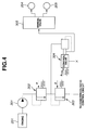
- FIG. 4 is a hydraulic circuit diagram in an embodiment
- FIG. 5 is a flowchart showing operation of the embodiment
- FIG. 6 is a map showing a transferred-torque characteristic in the embodiment
- FIG. 7 is a map similar to FIG. 6, showing another transferred-torque characteristic in the embodiment.
- FIG. 8 is a graph showing the relationship between the oil temperature and the engine speed in the embodiment.
- FIG. 9 is a time chart showing switching of creep control in the embodiment.
- FIG. 10 is a chart similar to FIG. 9, showing switching from creep control to start control in the embodiment.
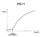
- FIG. 11 is a graph similar to FIG. 8, showing a current-torque characteristic of an electromagnetic multiple disk clutch in the embodiment.
- a vehicle driving system comprises an engine electronic control unit (EECU) 101, an automatic-transmission electronic control unit (ATECU) 102, a throttle-valve opening sensor 103, an engine-speed sensor 104, an inhibitor switch 105, an oil-temperature sensor 106, a vehicle-velocity sensors 107, an engine 201, an electromagnetic clutch or electromagnetic multiple disk clutch 202, a forward/reverse switching mechanism 206, and an automatic transmission 207.
- ECU engine electronic control unit
- ATECU automatic-transmission electronic control unit
- Engine rotation outputted from the engine 201 is transmitted to the electromagnetic multiple disk clutch 202, which is then transmitted to the forward/reverse switching mechanism 206.
- the forward/reverse switching mechanism 206 comprises a planetary-gear set 203, a forward clutch 204, and a reverse brake 205.
- the planetary-gear gear 203 comprises a sun gear S connected to a transmission input shaft, a carrier C connected to a reverse brake 205 which can engage with a transmission casing, and a ring gear R connected to an electromagnetic-multiple-disk-clutch output shaft.
- the engine speed sensed by the engine-speed sensor 104 and the throttle-valve opening (TVO) sensed by the throttle-valve opening sensor 103 are inputted to the EECU 101.
- the driver's selected shift range detected by the inhibitor switch 105, the oil temperature sensed by the oil-temperature sensor 106, and the vehicle velocity sensed by the vehicle-velocity sensor 107 are inputted to the ATECU 102.
- the EECU 101 controls the engine 201 in accordance with detected sensor signals.
- the ATECU 102 controls the electromagnetic multiple disk clutch 202, forward/reverse switching mechanism 206, and automatic transmission 207 in accordance with detected sensor signals.
- the EECU 101 and the ATECU 102 transmit signals mutually to achieve optimal drive-system control.
- FIG. 2 shows electromagnetic multiple disk clutch 202 and its surroundings in the embodiment. A description is omitted about shift operation, etc. of the transmission mechanism of the automatic transmission 207 used in the embodiment.
- a converter housing 4 as a stationary-side housing is attached to a front-end opening of the transmission casing 3.
- a front cover 7 is attached to the converter housing 4.
- the transmission casing 3, part of the converter housing 4, and front cover 7 define a first compartment 3b to which lubrication is ensured.
- the front cover 7 defines a second compartment 3c which opens to the air and accommodates a torsional damper 6.
- An oil pump 2 is interposed between the transmission casing 3 and the converter housing 4.
- the oil pump 2 is a typical gear pump constructed by accommodating an internal gear pump element in the space defined by a pump housing 2a and a pump cover 2b.
- a stationary hollow sleeve 2c is engaged on the inner periphery of the pump cover 2b to rotatably receive an input shaft 1 therein.
- the electromagnetic multiple disk clutch 202 is arranged on a front end of the input shaft 1 which projects into the converter housing 4.
- the clutch 202 comprises an input clutch pack 12 formed by engagement between a spline 9a of a first input drum 9 and a spline 11a of a second input drum 11.
- a rotor 17 is unitarily rotatably engaged with the second input drum 11, and a drive-side clutch plate 16c including an armature 16b of an electromagnetic clutch 16 is also engaged therewith.
- An electromagnet 16a is relatively rotatably supported through a bearing 17a provided to the rotor 17.
- a driven-side clutch plate 16d of the electromagnetic clutch 16 is engaged with a torque cam member 18.
- rotation of the second input drum 11 is transmitted to the torque cam member 18.
- a loading cam 14 is arranged on the side face of the torque cam member 18 to produce axial thrust force between the torque cam member 18 and an input clutch hub 13.
- the input clutch pack 12 is engaged by the above axial thrust force. With this engagement, torque transmitted to the first input drum 9 is transmitted to the input clutch hub 13, which is in turn transmitted to the input shaft 1. Specifically, after engagement of the input clutch pack 12, engine torque is transmitted to the input clutch hub 13 directly and not through the electromagnetic clutch 16, which is in turn transmitted to the input shaft 1.
- the electromagnetic clutch 202 includes electromagnetic multiple disk clutch.
- transmitted engine torque is amplified by the loading cam 14 to engage the input clutch pack 12 serving as a main wet clutch, achieving direct transmission of engine torque from the input clutch hub 13 to the input shaft 1.
- FIGS. 3A-3C are collinear diagrams show change in engine speed due to engagement of the forward clutch 204 or the reverse brake 205 in the embodiment.
- engine rotation outputted from the electromagnetic multiple disk clutch 202 is inputted to the ring gear R of the forward/reverse switching mechanism 206.
- FIG. 3A is a collinear diagram during full engagement of the forward clutch 204. Due to full engagement of the forward clutch 204, engine rotation inputted to the ring gear R is inputted to the sun gear S as it is, which is then inputted to the automatic transmission 207.
- FIG. 3B is a collinear diagram during slip engagement of the forward clutch 204. Since the forward clutch 204 engages while slipping, engine rotation inputted to the ring gear R is reduced in rotational speed and outputted to the sun gear S, which is then outputted to the automatic transmission 207. Specifically, engine rotation outputted from the electromagnetic multiple disk clutch 202 is reduced in rotational speed and outputted to the automatic transmission 207.
- FIG. 3C is a collinear diagram during engagement of the reverse brake 205.
- the reverse brake 205 When the vehicle rolls backward, only the reverse brake 205 is engaged so that rotation inputted to the ring gear R is reduced and reversed to be outputted to the sun gear S, which is then inputted to the automatic transmission 207.
- a pump 301 When a pump 301 is driven by the engine 201 to produce the hydraulic pressure, the pressure within the circuit is adjusted at a predetermined pressure by a first relief valve 302 and a second relief valve 303, which is supplied to a forward/reverse hydraulic-pressure control valve 304.
- the forward/reverse hydraulic-pressure control valve 304 is a reducing valve, and serves to adjust the hydraulic pressure to be supplied to a manual valve 305 in accordance with the discharge of lubricating oil from a drain port.
- the control valve 304 is constructed such that when only a spring load is active therein, the rate of discharge of lubricating oil from the drain port is larger, and the rate of the hydraulic pressure to be supplied to the manual valve 305 is smaller. With this, when only a spring load is active in the control valve 304, small hydraulic pressure corresponding to creep can be supplied to the manual valve 305.
- a command signal Pcsig is inputted to the control valve 304, a predetermined hydraulic pressure is produced accordingly.
- the hydraulic pressure produced in the control valve 304 is supplied to the forward clutch 204 and the reverse brake 205 through the manual valve 305.
- the forward/reverse hydraulic-pressure control valve 304 can secure the engagement capacity corresponding to creep by only the spring characteristic which is not affected by the oil temperature, resulting in accurate hydraulic control even at very low temperature. Moreover, since small engagement capacity corresponding to creep can be secured by a spring load only, the oil amount required for engagement can be reduced, resulting in improvement in fuel consumption.
- step S401 it is determined whether or not the brake is depressed. If it is determined that the brake is depressed, control proceeds to a step S415, whereas if it is determined that the brake is not depressed, control proceeds to a step S402.
- the oil temperature within the automatic transmission 207 is detected.
- step S403 it is determined whether or not the driver's selected shift range is D or R range showing his/her driving intention. If it is determined that the shift range is D or R range, control proceeds to a step S404, whereas if it is determined that the shift range is not D or R range, control proceeds to the step S415.
- TVO throttle-valve opening
- start processing is carried out by turning on the command signal Pcsig to the forward/reverse hydraulic-pressure control valve 304, setting the engagement capacity of the forward clutch 204 or reverse brake 205 at engine torque or more as a map 4 shown in FIG. 7, and slip-controlling the electromagnetic multiple disk clutch 202.
- step S407 it is determined whether or not the oil temperature is equal to or smaller than a threshold value 1. If it is determined that the oil temperature ⁇ threshold value 1, control proceeds to a step S409, whereas if it is determined that the oil temperature > threshold value 1, control proceeds to a step S408.
- step S408 ordinary-temperature creep control processing is carried out by setting at a predetermined value P1 the command signal Pcsig to the forward/reverse hydraulic-pressure control valve 304, setting the engagement capacity of the forward clutch 204 or reverse brake 205 as a map 2 shown in FIG. 7, and controlling the electromagnetic multiple disk clutch 202 in accordance with a map 1 shown in FIG. 7.
- step S409 it is determined whether the oil temperature is equal to or smaller than a threshold value 2. If it is determined that the oil temperature ⁇ threshold value 2, control proceeds to a step S411, whereas if it is determined that the oil temperature > threshold value 2, control proceeds to a step S410.
- second creep control processing is carried out by setting at 0 the command signal Pcsig to the forward/reverse hydraulic-pressure control valve 304, setting the engagement capacity of the forward clutch 204 or reverse brake 205 as shown in the map 1, and controlling the electromagnetic multiple disk clutch 202 in accordance with the map 2.
- the engine speed is increased in accordance with a map 5 shown in FIG. 8.
- first creep control processing is carried out by setting at predetermined value P1 the command signal Pcsig to the forward/reverse hydraulic-pressure control valve 304, setting the engagement capacity of the forward clutch 204 or reverse brake 205 as shown in the map 2, and outputting a non-engagement command to the electromagnetic multiple disk clutch 202.
- stop processing is carried out by outputting a non-engagement command to the electromagnetic multiple disk clutch 202.
- the electromagnetic multiple disk clutch 202 has smaller drag torque, and thus higher controllability, so that the electromagnetic multiple disk clutch 202 serves as a start element to carry out creep control in accordance with the map 1.
- the command signal Pcsig is set at 0 as described above to achieve the characteristics shown in the map 1 by a spring load of the forward/reverse hydraulic-pressure control valve 304 only.
- the command signal Pcsig is set at predetermined value P1 to supply higher hydraulic pressure to the forward clutch 204 or reverse brake 205, achieving the characteristics shown in the map 2.
- a non-engagement command is outputted to the electromagnetic multiple disk clutch 202, accelerating heat generation by active slip.
- FIG. 7 shows transferred torque when TVO ⁇ 0 in the embodiment.
- TVO ⁇ 0 i.e. the accelerator is depressed
- the torque capacity of the forward clutch 204 (or reverse brake 205) is set to be higher than input torque (engine torque) in accordance with the map 4, which is the capacity allowing full engagement.
- the electromagnetic multiple disk clutch 202 serves as a start element. Under the situation that start takes place, no control of feeble engagement force is needed contrary to during creep, so that the electromagnetic multiple disk clutch 202 serves as a start element.
- FIG. 8 shows map 5 illustrating the relationship between the oil temperature and the engine speed in the embodiment.
- the engine speed is increased with the oil temperature.
- the engine speed is increased in proportion as the oil temperature lowers. Since the engine speed is increased in proportion as the oil temperature lowers, engine stop can be prevented from occurring at N-D select or N-R select.
- an increase in engine allows a rise in oil temperature due to agitation of oil.
- Heat generation amount (transferred torque) x (relative rotational speed).
- Heat generation per unit time of the clutch is increased by increasing transferred torque and relative rotational speed.
- relative rotational speed is increased by increasing the engine speed on the input side, and the engagement torque capacity of the forward clutch 204 (or reverse brake 205) is set to be higher than a torque value required for creep. This allows not only compensation of the shortage of the oil amount, but increase in amount of self heat generation of the forward clutch 204 (or reverse clutch 20) by slippage, raising the oil temperature quickly, resulting in possible shift to current control for the electromagnetic multiple disk clutch 202.
- the engine speed is increased in accordance with the map 5 shown in FIG. 8. Since the driver's selected shift range detected by the inhibitor switch 105 is P or N range, and the brake is depressed, the electromagnetic multiple disk clutch 202 and the forward clutch 204 or reverse brake 205 are put in non-engagement.
- the electromagnetic multiple disk clutch 202 when increasing the engine speed based on the oil temperature in accordance with the map 5 shown in FIG. 8, the electromagnetic multiple disk clutch 202 is in non-engagement, whereas since the electromagnetic multiple disk clutch 202 is greater in drag torque than the electromagnetic multiple disk clutch 202 and the forward clutch 204 (or reverse brake 205), the forward clutch 204 (or reverse brake 205) produces slip actively. Since the oil viscosity is higher due to low oil temperature to provide less lubrication amount to the electromagnetic multiple disk clutch 202, frictional heat is produced between the clutch plates, thus allowing increasing of the oil temperature.
- first creep control processing is carried out by outputting a non-engagement command to the electromagnetic multiple disk clutch 202 and setting the command signal Pcsig for the engagement torque capacity of the forward clutch 204 (or reverse brake 205) at predetermined value P1 which is higher than the value for producing actual creep torque, ensuring creep control with the forward clutch 204 (or reverse brake 205).
- the engine speed is increased in proportion as the oil temperature lowers in accordance with the map 5.
- the reason that the command signal Pcsig is set at higher value P1 is to increase the heat generation amount while coping with possible non-supply of required amount of oil caused by the high oil viscosity due to low oil temperature.
- the engine speed is increased to thereby prevent engine stop and increase the slip amount actively, achieving a rise in oil temperature by oil agitation and self heat generation.
- the start element for carrying out creep control is switched from the forward clutch 204 (or the reverse brake 205) to the electromagnetic multiple disk clutch 20, carrying out ordinary-temperature creep control processing.
- FIG. 10 is a time chart when the vehicle starts during low-temperature creep control (during execution of first or creep control processing). Note that since operation from time t1 to time t3 is the same as that shown in FIG. 9, only different points will be described.
- start control is carried out with the electromagnetic multiple disk clutch 202, allowing start of higher controllability.
- the current-torque characteristic of the electromagnetic multiple disk clutch 202 in the embodiment will be described.
- the current-torque characteristic of the electromagnetic multiple disk clutch 202 in the low-torque area, has a point where torque rises sharply.
- the electromagnetic multiple disk clutch 202 is under current control, and thus has a point where torque rises sharply in the low-torque area.
- the use of a value near the point where torque rises sharply may result in occurrence of judder.
- creep control is carried out using the forward clutch 204 (or reverse brake 205) as a start element to restrain occurrence of judder. And in other areas (at the time of start), start of higher controllability is achieved with the electromagnetic multiple disk clutch 202.
- the start element is switched between the electromagnetic multiple disk clutch 202 and the forward clutch 204 (or reverse brake 205) in accordance with the oil temperature and the throttle-valve opening. This allows achievement of stable creep control at very low temperature.
- the electromagnetic clutch includes electromagnetic multiple disk clutch 202 with loading cam 14.
- the electromagnetic multiple disk clutch 202 provides high controllability by small electromagnetic force, but it is often affected by drag torque at low oil temperature, etc.
- the start element is switched to the forward clutch 204 (or reverse brake 205) as described above, stable creep control can be achieved at all times.
- the torque capacity of the forward clutch 204 (or reverse brake 205) is set to correspond to creep torque, and a non-engagement command is provided to the electromagnetic multiple disk clutch 202. Torque of the electromagnetic multiple disk clutch 202 becomes higher by drag torque due to low oil temperature. However, since the forward clutch 204 (or reverse brake 205) is creep-controlled to produce stable creep torque, and a non-engagement command is provided to the electromagnetic multiple disk clutch 202, active slippage can be obtained to increase the oil temperature by oil agitation and heat generation.
- the engagement command P1 for providing torque greater than torque required for creep is provided to the forward/reverse hydraulic-pressure control valve 304.
- the engine speed is increased to thereby prevent engine stop and increase actively the slip amount of the electromagnetic multiple disk clutch 202 and the forward clutch 204 (or reverse brake 205), resulting in a rise in oil temperature by oil agitation and self heat generation.
Landscapes
- Engineering & Computer Science (AREA)
- Mechanical Engineering (AREA)
- Transportation (AREA)
- General Engineering & Computer Science (AREA)
- Combustion & Propulsion (AREA)
- Physics & Mathematics (AREA)
- Chemical & Material Sciences (AREA)
- Electromagnetism (AREA)
- Fluid Mechanics (AREA)
- Automation & Control Theory (AREA)
- Control Of Transmission Device (AREA)
- Hydraulic Clutches, Magnetic Clutches, Fluid Clutches, And Fluid Joints (AREA)
- Mechanical Operated Clutches (AREA)
- Control Of Driving Devices And Active Controlling Of Vehicle (AREA)
Applications Claiming Priority (1)
| Application Number | Priority Date | Filing Date | Title |
|---|---|---|---|
| JP2004237582A JP4102341B2 (ja) | 2004-08-17 | 2004-08-17 | 自動変速機の制御装置 |
Publications (3)
| Publication Number | Publication Date |
|---|---|
| EP1628031A2 true EP1628031A2 (de) | 2006-02-22 |
| EP1628031A3 EP1628031A3 (de) | 2010-10-06 |
| EP1628031B1 EP1628031B1 (de) | 2013-01-02 |
Family
ID=35033526
Family Applications (1)
| Application Number | Title | Priority Date | Filing Date |
|---|---|---|---|
| EP05017781A Ceased EP1628031B1 (de) | 2004-08-17 | 2005-08-16 | Vorrichtung und Verfahren zur Steuerung eines Automatikgetriebes |
Country Status (3)
| Country | Link |
|---|---|
| US (1) | US7399257B2 (de) |
| EP (1) | EP1628031B1 (de) |
| JP (1) | JP4102341B2 (de) |
Families Citing this family (9)
| Publication number | Priority date | Publication date | Assignee | Title |
|---|---|---|---|---|
| JP4639829B2 (ja) * | 2005-02-02 | 2011-02-23 | トヨタ自動車株式会社 | 車両の制御装置 |
| JP2008039159A (ja) * | 2006-08-10 | 2008-02-21 | Hitachi Ltd | 自動車の制御装置 |
| KR20090001402A (ko) * | 2007-06-29 | 2009-01-08 | 엘지전자 주식회사 | 방송 수신이 가능한 텔레매틱스 단말기 및 방송 신호 처리방법 |
| CN101779390B (zh) * | 2007-06-29 | 2013-01-02 | Lg电子株式会社 | 广播接收系统和处理广播信号的方法 |
| JP4285570B2 (ja) * | 2007-09-11 | 2009-06-24 | トヨタ自動車株式会社 | 車両の制御装置 |
| JP5312362B2 (ja) * | 2010-01-29 | 2013-10-09 | ジヤトコ株式会社 | 多板摩擦係合装置における摩擦板の固着防止構造 |
| WO2012172639A1 (ja) * | 2011-06-14 | 2012-12-20 | トヨタ自動車株式会社 | 車両の制御装置 |
| KR102324757B1 (ko) * | 2017-05-02 | 2021-11-10 | 현대자동차주식회사 | 차량용 클러치 제어방법 |
| WO2019072383A1 (en) | 2017-10-11 | 2019-04-18 | Volvo Truck Corporation | METHOD FOR CONTROLLING CLUTCH ARRANGEMENT |
Citations (2)
| Publication number | Priority date | Publication date | Assignee | Title |
|---|---|---|---|---|
| EP1291540A2 (de) | 2001-09-06 | 2003-03-12 | JATCO Ltd | Steuerungssystem und -verfahren einer elektromagnetischen Mehrscheibenkupplung |
| US20040112171A1 (en) | 2001-01-12 | 2004-06-17 | Jochen Kuhstrebe | Motor vehicle comprising a drive train having a multiple clutch drive |
Family Cites Families (13)
| Publication number | Priority date | Publication date | Assignee | Title |
|---|---|---|---|---|
| JPS628838A (ja) * | 1985-07-05 | 1987-01-16 | Nissan Motor Co Ltd | 自動変速機の発進クラツチ制御装置 |
| US4964317A (en) * | 1987-08-10 | 1990-10-23 | Suzuki Jidosha Kogyo Kabushiki Kaisha | Hydraulic control method for continuously variable speed change gear mechanism for a vehicle and a drive control method for a pressure valve thereof |
| JPH0160029U (de) * | 1987-10-12 | 1989-04-17 | ||
| JP3861340B2 (ja) * | 1996-09-11 | 2006-12-20 | アイシン・エィ・ダブリュ株式会社 | 車両用動力伝達装置の電動オイルポンプ制御装置 |
| JP3429963B2 (ja) * | 1996-11-01 | 2003-07-28 | トヨタ自動車株式会社 | 自動変速機付き内燃機関の制御装置 |
| JP3585207B2 (ja) * | 1997-08-28 | 2004-11-04 | 本田技研工業株式会社 | ロックアップクラッチの制御装置 |
| JP3432773B2 (ja) * | 1999-07-21 | 2003-08-04 | 本田技研工業株式会社 | アイドル運転停止車両における発進クラッチの制御装置 |
| JP4125494B2 (ja) | 2001-03-08 | 2008-07-30 | ジヤトコ株式会社 | 電磁多板クラッチ |
| JP3551178B2 (ja) * | 2001-09-10 | 2004-08-04 | 日産自動車株式会社 | 車両のクラッチ制御装置 |
| JP4090260B2 (ja) * | 2002-03-28 | 2008-05-28 | ジヤトコ株式会社 | 電磁多板クラッチの制御装置 |
| JP2004150531A (ja) * | 2002-10-30 | 2004-05-27 | Toyota Motor Corp | 車両の発進制御装置 |
| JP3915698B2 (ja) * | 2002-12-27 | 2007-05-16 | アイシン・エィ・ダブリュ株式会社 | ハイブリッド車輌の制御装置 |
| JP3964333B2 (ja) * | 2003-02-06 | 2007-08-22 | ジヤトコ株式会社 | 自動変速機の変速油圧装置 |
-
2004
- 2004-08-17 JP JP2004237582A patent/JP4102341B2/ja not_active Expired - Fee Related
-
2005
- 2005-08-11 US US11/201,329 patent/US7399257B2/en not_active Expired - Fee Related
- 2005-08-16 EP EP05017781A patent/EP1628031B1/de not_active Ceased
Patent Citations (2)
| Publication number | Priority date | Publication date | Assignee | Title |
|---|---|---|---|---|
| US20040112171A1 (en) | 2001-01-12 | 2004-06-17 | Jochen Kuhstrebe | Motor vehicle comprising a drive train having a multiple clutch drive |
| EP1291540A2 (de) | 2001-09-06 | 2003-03-12 | JATCO Ltd | Steuerungssystem und -verfahren einer elektromagnetischen Mehrscheibenkupplung |
Also Published As
| Publication number | Publication date |
|---|---|
| EP1628031B1 (de) | 2013-01-02 |
| US7399257B2 (en) | 2008-07-15 |
| EP1628031A3 (de) | 2010-10-06 |
| JP2006057655A (ja) | 2006-03-02 |
| JP4102341B2 (ja) | 2008-06-18 |
| US20060040789A1 (en) | 2006-02-23 |
Similar Documents
| Publication | Publication Date | Title |
|---|---|---|
| US5086894A (en) | Lock-up clutch control system for automatic power transmission | |
| US7815545B2 (en) | Hydraulic control system for automatic transmission | |
| US8768590B2 (en) | Control device for an automatic transmission | |
| EP1471288A2 (de) | Schmiersteuervorrichtung und -Methode für Automatikgetriebe | |
| US9145931B2 (en) | Control device for vehicular lockup clutch | |
| US6843754B2 (en) | Control apparatus for an automatic transmission and a method for controlling the same | |
| US10808735B2 (en) | Transmission park valve with steel saddle | |
| EP1628031B1 (de) | Vorrichtung und Verfahren zur Steuerung eines Automatikgetriebes | |
| EP1502804B1 (de) | Schaltsteuerung für Automatikgetriebe | |
| US6969340B2 (en) | Control apparatus and control method for automatic transmission | |
| US20040116244A1 (en) | System and method of controlling V-belt type continuously variable transmission | |
| US20110094842A1 (en) | Control apparatus for lockup clutch | |
| JP2003314591A (ja) | 自動変速機の変速油圧装置 | |
| US5643137A (en) | Lockup control apparatus for automatic transmission and the method thereof | |
| EP1291540B1 (de) | Steuerungssystem und -verfahren einer elektromagnetischen Mehrscheibenkupplung | |
| US11059471B2 (en) | Power transmission device and method for controlling same | |
| JP2000179661A (ja) | 車両用自動変速機の制御装置 | |
| JP2847733B2 (ja) | 自動変速機用油圧制御装置 | |
| US10830351B2 (en) | Method for disengaging hydraulic park | |
| JP2833345B2 (ja) | 車両用自動変速装置の変速制御方法 | |
| JPH0942440A (ja) | 摩擦係合装置の劣化検出装置 | |
| US11692622B2 (en) | Transmission shift with pressure controlled cleaning pulses | |
| US10704677B2 (en) | Method of discharging transmission accumulator | |
| JP2003287058A (ja) | 電磁多板クラッチの制御装置 | |
| US20190011043A1 (en) | Transmission device |
Legal Events
| Date | Code | Title | Description |
|---|---|---|---|
| PUAI | Public reference made under article 153(3) epc to a published international application that has entered the european phase |
Free format text: ORIGINAL CODE: 0009012 |
|
| 17P | Request for examination filed |
Effective date: 20050816 |
|
| AK | Designated contracting states |
Kind code of ref document: A2 Designated state(s): AT BE BG CH CY CZ DE DK EE ES FI FR GB GR HU IE IS IT LI LT LU LV MC NL PL PT RO SE SI SK TR |
|
| AX | Request for extension of the european patent |
Extension state: AL BA HR MK YU |
|
| PUAL | Search report despatched |
Free format text: ORIGINAL CODE: 0009013 |
|
| AK | Designated contracting states |
Kind code of ref document: A3 Designated state(s): AT BE BG CH CY CZ DE DK EE ES FI FR GB GR HU IE IS IT LI LT LU LV MC NL PL PT RO SE SI SK TR |
|
| AX | Request for extension of the european patent |
Extension state: AL BA HR MK YU |
|
| AKX | Designation fees paid |
Designated state(s): DE FR GB IT |
|
| 17Q | First examination report despatched |
Effective date: 20110624 |
|
| GRAP | Despatch of communication of intention to grant a patent |
Free format text: ORIGINAL CODE: EPIDOSNIGR1 |
|
| GRAS | Grant fee paid |
Free format text: ORIGINAL CODE: EPIDOSNIGR3 |
|
| GRAA | (expected) grant |
Free format text: ORIGINAL CODE: 0009210 |
|
| AK | Designated contracting states |
Kind code of ref document: B1 Designated state(s): DE FR GB IT |
|
| REG | Reference to a national code |
Ref country code: GB Ref legal event code: FG4D |
|
| REG | Reference to a national code |
Ref country code: DE Ref legal event code: R096 Ref document number: 602005037675 Country of ref document: DE Effective date: 20130307 |
|
| PLBE | No opposition filed within time limit |
Free format text: ORIGINAL CODE: 0009261 |
|
| STAA | Information on the status of an ep patent application or granted ep patent |
Free format text: STATUS: NO OPPOSITION FILED WITHIN TIME LIMIT |
|
| 26N | No opposition filed |
Effective date: 20131003 |
|
| REG | Reference to a national code |
Ref country code: DE Ref legal event code: R097 Ref document number: 602005037675 Country of ref document: DE Effective date: 20131003 |
|
| GBPC | Gb: european patent ceased through non-payment of renewal fee |
Effective date: 20130816 |
|
| PG25 | Lapsed in a contracting state [announced via postgrant information from national office to epo] |
Ref country code: GB Free format text: LAPSE BECAUSE OF NON-PAYMENT OF DUE FEES Effective date: 20130816 |
|
| REG | Reference to a national code |
Ref country code: FR Ref legal event code: PLFP Year of fee payment: 12 |
|
| PGFP | Annual fee paid to national office [announced via postgrant information from national office to epo] |
Ref country code: DE Payment date: 20160809 Year of fee payment: 12 Ref country code: IT Payment date: 20160822 Year of fee payment: 12 |
|
| REG | Reference to a national code |
Ref country code: FR Ref legal event code: PLFP Year of fee payment: 13 |
|
| PGFP | Annual fee paid to national office [announced via postgrant information from national office to epo] |
Ref country code: FR Payment date: 20170714 Year of fee payment: 13 |
|
| REG | Reference to a national code |
Ref country code: DE Ref legal event code: R119 Ref document number: 602005037675 Country of ref document: DE |
|
| PG25 | Lapsed in a contracting state [announced via postgrant information from national office to epo] |
Ref country code: DE Free format text: LAPSE BECAUSE OF NON-PAYMENT OF DUE FEES Effective date: 20180301 |
|
| PG25 | Lapsed in a contracting state [announced via postgrant information from national office to epo] |
Ref country code: IT Free format text: LAPSE BECAUSE OF NON-PAYMENT OF DUE FEES Effective date: 20170816 |
|
| PG25 | Lapsed in a contracting state [announced via postgrant information from national office to epo] |
Ref country code: FR Free format text: LAPSE BECAUSE OF NON-PAYMENT OF DUE FEES Effective date: 20180831 |