EP1291540A2 - Steuerungssystem und -verfahren einer elektromagnetischen Mehrscheibenkupplung - Google Patents
Steuerungssystem und -verfahren einer elektromagnetischen Mehrscheibenkupplung Download PDFInfo
- Publication number
- EP1291540A2 EP1291540A2 EP02019053A EP02019053A EP1291540A2 EP 1291540 A2 EP1291540 A2 EP 1291540A2 EP 02019053 A EP02019053 A EP 02019053A EP 02019053 A EP02019053 A EP 02019053A EP 1291540 A2 EP1291540 A2 EP 1291540A2
- Authority
- EP
- European Patent Office
- Prior art keywords
- overexcitation
- control
- electromagnetic clutch
- current
- disc electromagnetic
- Prior art date
- Legal status (The legal status is an assumption and is not a legal conclusion. Google has not performed a legal analysis and makes no representation as to the accuracy of the status listed.)
- Granted
Links
- 238000000034 method Methods 0.000 title claims abstract description 19
- 230000005540 biological transmission Effects 0.000 claims description 48
- 239000003921 oil Substances 0.000 claims description 23
- 239000010687 lubricating oil Substances 0.000 claims description 14
- 230000001276 controlling effect Effects 0.000 claims description 9
- 230000001105 regulatory effect Effects 0.000 claims description 8
- 230000033228 biological regulation Effects 0.000 claims description 7
- 230000005284 excitation Effects 0.000 abstract description 4
- 238000002485 combustion reaction Methods 0.000 description 6
- 239000002184 metal Substances 0.000 description 5
- 230000007246 mechanism Effects 0.000 description 4
- 230000007423 decrease Effects 0.000 description 3
- 230000000977 initiatory effect Effects 0.000 description 3
- 230000009471 action Effects 0.000 description 2
- 238000012544 monitoring process Methods 0.000 description 2
- 230000008859 change Effects 0.000 description 1
- 238000006243 chemical reaction Methods 0.000 description 1
- 230000003247 decreasing effect Effects 0.000 description 1
- 238000001514 detection method Methods 0.000 description 1
- 230000005672 electromagnetic field Effects 0.000 description 1
- 230000001050 lubricating effect Effects 0.000 description 1
- 238000005461 lubrication Methods 0.000 description 1
- 230000004048 modification Effects 0.000 description 1
- 238000012986 modification Methods 0.000 description 1
- 238000005086 pumping Methods 0.000 description 1
- 238000005096 rolling process Methods 0.000 description 1
- 230000003746 surface roughness Effects 0.000 description 1
Images


Classifications
-
- F—MECHANICAL ENGINEERING; LIGHTING; HEATING; WEAPONS; BLASTING
- F16—ENGINEERING ELEMENTS AND UNITS; GENERAL MEASURES FOR PRODUCING AND MAINTAINING EFFECTIVE FUNCTIONING OF MACHINES OR INSTALLATIONS; THERMAL INSULATION IN GENERAL
- F16D—COUPLINGS FOR TRANSMITTING ROTATION; CLUTCHES; BRAKES
- F16D48/00—External control of clutches
- F16D48/06—Control by electric or electronic means, e.g. of fluid pressure
- F16D48/064—Control of electrically or electromagnetically actuated clutches
-
- F—MECHANICAL ENGINEERING; LIGHTING; HEATING; WEAPONS; BLASTING
- F16—ENGINEERING ELEMENTS AND UNITS; GENERAL MEASURES FOR PRODUCING AND MAINTAINING EFFECTIVE FUNCTIONING OF MACHINES OR INSTALLATIONS; THERMAL INSULATION IN GENERAL
- F16D—COUPLINGS FOR TRANSMITTING ROTATION; CLUTCHES; BRAKES
- F16D2500/00—External control of clutches by electric or electronic means
- F16D2500/10—System to be controlled
- F16D2500/104—Clutch
- F16D2500/10406—Clutch position
- F16D2500/10412—Transmission line of a vehicle
-
- F—MECHANICAL ENGINEERING; LIGHTING; HEATING; WEAPONS; BLASTING
- F16—ENGINEERING ELEMENTS AND UNITS; GENERAL MEASURES FOR PRODUCING AND MAINTAINING EFFECTIVE FUNCTIONING OF MACHINES OR INSTALLATIONS; THERMAL INSULATION IN GENERAL
- F16D—COUPLINGS FOR TRANSMITTING ROTATION; CLUTCHES; BRAKES
- F16D2500/00—External control of clutches by electric or electronic means
- F16D2500/10—System to be controlled
- F16D2500/108—Gear
- F16D2500/1081—Actuation type
- F16D2500/1085—Automatic transmission
-
- F—MECHANICAL ENGINEERING; LIGHTING; HEATING; WEAPONS; BLASTING
- F16—ENGINEERING ELEMENTS AND UNITS; GENERAL MEASURES FOR PRODUCING AND MAINTAINING EFFECTIVE FUNCTIONING OF MACHINES OR INSTALLATIONS; THERMAL INSULATION IN GENERAL
- F16D—COUPLINGS FOR TRANSMITTING ROTATION; CLUTCHES; BRAKES
- F16D2500/00—External control of clutches by electric or electronic means
- F16D2500/30—Signal inputs
- F16D2500/306—Signal inputs from the engine
- F16D2500/3067—Speed of the engine
-
- F—MECHANICAL ENGINEERING; LIGHTING; HEATING; WEAPONS; BLASTING
- F16—ENGINEERING ELEMENTS AND UNITS; GENERAL MEASURES FOR PRODUCING AND MAINTAINING EFFECTIVE FUNCTIONING OF MACHINES OR INSTALLATIONS; THERMAL INSULATION IN GENERAL
- F16D—COUPLINGS FOR TRANSMITTING ROTATION; CLUTCHES; BRAKES
- F16D2500/00—External control of clutches by electric or electronic means
- F16D2500/30—Signal inputs
- F16D2500/306—Signal inputs from the engine
- F16D2500/3069—Engine ignition switch
-
- F—MECHANICAL ENGINEERING; LIGHTING; HEATING; WEAPONS; BLASTING
- F16—ENGINEERING ELEMENTS AND UNITS; GENERAL MEASURES FOR PRODUCING AND MAINTAINING EFFECTIVE FUNCTIONING OF MACHINES OR INSTALLATIONS; THERMAL INSULATION IN GENERAL
- F16D—COUPLINGS FOR TRANSMITTING ROTATION; CLUTCHES; BRAKES
- F16D2500/00—External control of clutches by electric or electronic means
- F16D2500/30—Signal inputs
- F16D2500/308—Signal inputs from the transmission
- F16D2500/30802—Transmission oil properties
- F16D2500/30803—Oil temperature
-
- F—MECHANICAL ENGINEERING; LIGHTING; HEATING; WEAPONS; BLASTING
- F16—ENGINEERING ELEMENTS AND UNITS; GENERAL MEASURES FOR PRODUCING AND MAINTAINING EFFECTIVE FUNCTIONING OF MACHINES OR INSTALLATIONS; THERMAL INSULATION IN GENERAL
- F16D—COUPLINGS FOR TRANSMITTING ROTATION; CLUTCHES; BRAKES
- F16D2500/00—External control of clutches by electric or electronic means
- F16D2500/30—Signal inputs
- F16D2500/31—Signal inputs from the vehicle
- F16D2500/3102—Vehicle direction of travel, i.e. forward/reverse
-
- F—MECHANICAL ENGINEERING; LIGHTING; HEATING; WEAPONS; BLASTING
- F16—ENGINEERING ELEMENTS AND UNITS; GENERAL MEASURES FOR PRODUCING AND MAINTAINING EFFECTIVE FUNCTIONING OF MACHINES OR INSTALLATIONS; THERMAL INSULATION IN GENERAL
- F16D—COUPLINGS FOR TRANSMITTING ROTATION; CLUTCHES; BRAKES
- F16D2500/00—External control of clutches by electric or electronic means
- F16D2500/30—Signal inputs
- F16D2500/316—Other signal inputs not covered by the groups above
- F16D2500/3166—Detection of an elapsed period of time
-
- F—MECHANICAL ENGINEERING; LIGHTING; HEATING; WEAPONS; BLASTING
- F16—ENGINEERING ELEMENTS AND UNITS; GENERAL MEASURES FOR PRODUCING AND MAINTAINING EFFECTIVE FUNCTIONING OF MACHINES OR INSTALLATIONS; THERMAL INSULATION IN GENERAL
- F16D—COUPLINGS FOR TRANSMITTING ROTATION; CLUTCHES; BRAKES
- F16D2500/00—External control of clutches by electric or electronic means
- F16D2500/50—Problem to be solved by the control system
- F16D2500/504—Relating the engine
- F16D2500/5045—Control of engine at idle, i.e. controlling engine idle conditions, e.g. idling speed
-
- F—MECHANICAL ENGINEERING; LIGHTING; HEATING; WEAPONS; BLASTING
- F16—ENGINEERING ELEMENTS AND UNITS; GENERAL MEASURES FOR PRODUCING AND MAINTAINING EFFECTIVE FUNCTIONING OF MACHINES OR INSTALLATIONS; THERMAL INSULATION IN GENERAL
- F16D—COUPLINGS FOR TRANSMITTING ROTATION; CLUTCHES; BRAKES
- F16D2500/00—External control of clutches by electric or electronic means
- F16D2500/50—Problem to be solved by the control system
- F16D2500/51—Relating safety
- F16D2500/5108—Failure diagnosis
-
- F—MECHANICAL ENGINEERING; LIGHTING; HEATING; WEAPONS; BLASTING
- F16—ENGINEERING ELEMENTS AND UNITS; GENERAL MEASURES FOR PRODUCING AND MAINTAINING EFFECTIVE FUNCTIONING OF MACHINES OR INSTALLATIONS; THERMAL INSULATION IN GENERAL
- F16D—COUPLINGS FOR TRANSMITTING ROTATION; CLUTCHES; BRAKES
- F16D2500/00—External control of clutches by electric or electronic means
- F16D2500/50—Problem to be solved by the control system
- F16D2500/51—Relating safety
- F16D2500/5114—Failsafe
-
- F—MECHANICAL ENGINEERING; LIGHTING; HEATING; WEAPONS; BLASTING
- F16—ENGINEERING ELEMENTS AND UNITS; GENERAL MEASURES FOR PRODUCING AND MAINTAINING EFFECTIVE FUNCTIONING OF MACHINES OR INSTALLATIONS; THERMAL INSULATION IN GENERAL
- F16D—COUPLINGS FOR TRANSMITTING ROTATION; CLUTCHES; BRAKES
- F16D2500/00—External control of clutches by electric or electronic means
- F16D2500/70—Details about the implementation of the control system
- F16D2500/704—Output parameters from the control unit; Target parameters to be controlled
- F16D2500/70402—Actuator parameters
- F16D2500/70418—Current
Definitions
- the present invention relates to a multiple-disc electromagnetic clutch control system and method for controlling power transmission between an engine and an automatic transmission of a vehicle.
- a clutch device which comprises a main clutch, an electromagnetic pilot clutch and a cam mechanism.
- the cam mechanism Upon engagement of the electromagnetic pilot clutch, the cam mechanism is operated by a torque transmitted thereto and generates a cam thrust force.
- the cam thrust force is applied to the main clutch via a press mechanism, thereby engaging the main clutch.
- the engagement of the electromagnetic pilot clutch is controlled through current regulation thereto, and the engaging force of the electromagnetic pilot clutch is increased by means of the cam mechanism. It is therefore possible not only to attain a large engaging force of the main clutch just by supplying a small current to the electromagnetic pilot clutch but also to control the engagement of the main clutch more closely through current regulation to the electromagnetic clutch than a conventional hydraulic clutch. For these reasons, attention is being given to the above-mentioned clutch device.
- the electromagnetic pilot clutch comprised of an electromagnet A, a plurality of clutch plates B and a retaining plate C and lubricated with a lubricating oil as shown in FIGS. 8A and 8B.
- CASE 1 The vehicle is parked on e.g. a downhill road for a long time with its engine stopped and its body held at an angle ⁇ relative to a horizon. Immediately after stopping the vehicle, the clutch plates B are at some distance from the electromagnet A. With the passage of time, however, the clutch plates B and the retaining plate C are moved away from the electromagnet A under the weight of the lubricating oil as well as under their own weights as shown in FIG. 8A.
- CASE 2 The vehicle is driven in a condition that the lubricating oil has reached a temperature of 80°C or higher, and then left standing for a long time with its engine stopped.
- the lubricating oil is in a state of thermally expanding immediately after stopping the vehicle, then gradually contracts with decrease in temperature and is dropped off.
- the retaining plate C is heavier in weight and has a larger sliding surface than the clutch plates B, thereby being liable to be acted upon by a larger frictional force via the sliding surface and allowed to stand still.
- the clutch plates B are shifted toward the retaining plate C (i.e. moved away from the electromagnet A) with the passage of time, as shown in FIG. 8B.
- CASE 3 A magnetic field produced by the electromagnet A for the engagement of the pilot clutch causes a residual field to the clutch plates B and the retaining plate C, whereby the clutch plates B and the retaining plate C are attracted to each other. Then, the clutch plates B are shifted toward the retaining plate C because of the difference in their weights and sliding frictions as mentioned in CASE 2.
- a multiple-disc electromagnetic clutch control system for controlling power transmission between an engine and an automatic transmission of a vehicle, the system comprising: a multiple-disc electromagnetic clutch having an electromagnet and a plurality of clutch plates; and a control unit for controlling engagement and disengagement of the multiple-disc electromagnetic clutch through current regulation to the multiple-disc electromagnetic clutch, the control unit having an adjusting section for adjusting, at start of the vehicle, an intervening space between the electromagnet and the clutch plates so that the intervening space falls within a predetermined range by executing an overexcitation control.
- a multiple-disc electromagnetic clutch control method for controlling power transmission between an engine and an automatic transmission of a vehicle by engaging and disengaging a multiple-disc electromagnetic clutch through current regulation to the multiple-disc electromagnetic clutch, the multiple-disc electromagnetic clutch having an electromagnet and a plurality of clutch plates, the method comprising adjusting, at start of the vehicle, an intervening space between the electromagnet and the clutch plates so that the intervening space falls within a predetermined range through an overexcitation control.
- FIG. 1 is a cross-sectional view of an input clutch device provided with a multiple-disc electromagnetic clutch to which the present invention is applicable.
- FIG. 2 is a flowchart for a program to execute an overexcitation control of the multiple-disc electromagnetic clutch according to a first embodiment of the present invention.
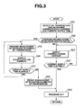
- FIG. 3 is a flowchart illustrating the detailed procedure of step S106 of FIG. 2.
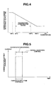
- FIG. 4 is one example of map used to determine an overexcitation current and current supply time.
- FIG. 5 is a timing chart for the overexcitation control according to the first embodiment of the present invention.
- FIG. 6 is a flowchart for a program to execute an overexcitation control of the multiple-disc electromagnetic clutch according to a second embodiment of the present invention.
- FIG. 7 is a flowchart showing the detailed procedure of step S106 of FIG. 6.
- FIGS. 8A and 8B are schematic illustrations showing conventional problems that arise in the multiple-disc electromagnetic clutch.
- FIG. 1 is a cross-sectional view of an input clutch device 5 disposed between an engine and an automatic transmission of a vehicle so as to control power transmission from the engine to the automatic transmission according to one exemplary embodiment of the present invention.
- an input clutch device 5 disposed between an engine and an automatic transmission of a vehicle so as to control power transmission from the engine to the automatic transmission according to one exemplary embodiment of the present invention.
- detailed explanations for the structures and operations of the engine and the automatic transmission will be omitted.
- a clutch housing 4 in which the input clutch device 5 is disposed is mounted to a transmission case 3, and a front cover 11 is fastened to the clutch housing 4 with a bolt 12.
- a first open chamber 4a for installing therein a torsion damper 6 is defined by the clutch housing 4 and the front cover 11, while a second chamber 3a for lubricating the input clutch device 5 therein is defined by the transmission case 3, the clutch housing 4 and the front cover 11.
- An oil pump 2 is disposed between the transmission case 3 and the clutch housing 4.
- the oil pump 2 is a typical gear pump of which the internal gear pump elements are covered with a pump housing 2a and a pump cover 2b.
- a hollow sleeve 2c is engaged in the pump cover 2, and a transmission input shaft 1 of the automatic transmission is rotatably inserted in the hollow sleeve 2c with its end portion protruded in the clutch housing 4.
- the input clutch device 5 is located around the protruded end portion of the transmission input shaft 1, and comprises an electromagnetic clutch 22, a multiple-disc clutch pack 15 on an outer circumferential side of the electromagnetic clutch 22, a loading cam 17 on an inner circumferential side of the electromagnetic clutch 22 and a clutch hub 16.
- the clutch pack 15 includes a floating plate 15a and an alternating series of facing plates 15b and metal plates 15c placed between clutch drums 13 and 14.
- the clutch drum 13 includes a first shaft portion 13b to which a power input hub 7 is fixed with a nut 8, a second shaft portion 13d held in sliding contact with an oil seal member 9 and a supported portion 13e at which the clutch drum 13 is supported by the front cover 11 via a bearing 10.
- the power input hub 7 is engaged with an output member 6a of the torsion damper 6 via a splined portion 7a so that the power input hub 7 and the output member 6a can rotate as a single unit.
- the clutch drums 13 and 14 are splined to each other.
- Each of the facing plates 15b has friction facings attached on both sides thereof.
- the facing plates 15b are engaged with the clutch hub 16 so that the facing plates 15b and the clutch hub 16 can rotate about the transmission input shaft 1 as a single unit
- the metal plates 15c are engaged with the clutch drum 14 so that the metal plates 15c and the clutch drum 14 can rotate about the transmission input shaft 1 as a single unit.
- the clutch pack 15 is equipped with a stepped retainer 15d and a snap ring 15e so that the snap ring 15e restricts the axial movement of the facing plates 15b and the metal plates 15c in a rightward direction of FIG. 1 via the retainer 15d.
- the electromagnetic clutch 22 functions as a pilot clutch, and comprises an electromagnet 22a, a retaining plate 22b, a plurality of clutch plates 22c and a rotor 24. Further, the rotor 24 is engaged with the clutch drum 14 so that the rotor 24 and the clutch drum 14 can rotate about the transmission input shaft 1 as a single unit, and equipped with a stopper 23. An end 24a of the rotor 24 functions as a driving pawl of the oil pump 2.
- the clutch hub 16 is splined to the transmission input shaft 1 and equipped with a snap ring 18 so that the snap ring 18 restricts the axial movement of the clutch hub 16 in a rightward direction of FIG. 1.
- the engine power is transmitted to the clutch drums 13 and 14 (i.e. the driving part) via the torsion damper 6 integral with a drive plate 6b and the power input hub 7 and then transmitted to the rotor 24.
- the electromagnet 22a is supplied with an excitation current and thereby generates an electromagnetic field
- the retaining plate 22b and the clutch plates 22c are attracted to the electromagnet 22a and forced together.
- the electromagnetic clutch 22 is thus engaged so as to output the engine power as a torque Tp to the loading cam 17.
- Tp M ⁇ E ⁇ ⁇ ⁇ r ⁇ n
- M a magnetic force produced by the electromagnet 22a upon excitation thereof
- E a magnetic path efficiency with which the magnetic force of the electromagnet 22a acts on the retaining plate 22b and the clutch plates 22c
- ⁇ a coefficient of friction of the plates 22b and 22c
- r a mean radius of the frictional surfaces of the plates 22b and 22c
- n is the number of the frictional surfaces.
- the magnetic path efficiency varies depending on the fact that the retaining plate 22b and the clutch plates 22c are surface treated and the areas of their frictional surfaces are not consistent with theoretical values owing to surface roughness and lubrication holes.
- the loading cam 17 converts the torque Tp into a cam thrust force that forces the clutch hub 16 to move in a rightward direction of FIG. 1 by the cam action of rolling balls on sloping surfaces.
- a thrust force that forces, via a thrust bearing 27, the clutch drum 14 to move in a leftward direction of FIG. 1 together with the rotor 24 and the electromagnet 22a against the spring tension of a return spring 19.
- the return spring 19 is fixed with a snap spring 20.
- the clutch drum 14 is eventually moved in the leftward direction of FIG. 1. It follows that the facing plates 15b and the metal plates 15c are forced together to establish the engagement of the clutch pack 15, whereby the engine power is transmitted to the transmission input shaft 1 through the clutch hub 16 (i.e. the driven part).
- the clutch pack 15, the electromagnetic pilot clutch 22 and the loading cam 17 are lubricated with a lubricating oil through a control valve (not shown).
- a conventional lock-up control valve can be used as such a control valve. More specifically, the lubricating oil is supplied by the centrifugal pumping action of the oil pump 2 through openings 1a, a hollow portion 1b and openings 1c and 1d of the transmission input shaft 1 and openings 13a of the clutch drum 13 to lubricate the input clutch device 5.
- the lubricating oil flows through a plurality of openings (not shown) formed in the clutch drums 13 and 14 into a space sealed by the clutch housing 4 and the front cover 11 and returns to an oil pan (not shown) provided on the transmission side via a drain port 4b formed in the clutch housing 4.
- the operation of the input clutch device 5 is controlled by means of a control unit. That is, the control unit controls the engagement and disengagement of the electromagnetic clutch 22 through current regulation thereto, thereby moving the clutch pack 15 into engagement and disengagement by operation of the loading cam 17 as described above.
- the control unit performs an overexcitation control at start of the vehicle for adjusting an intervening space between the electromagnet 22a and the clutch plates 22c so that the intervening space falls within a predetermined range.
- the overexcitation control is generally carried out before a normal excitation control by which the electromagnetic clutch 22 is engaged (refer to FIG. 5).
- FIG. 2 is a flowchart for a program to execute the overexcitation control according to a first embodiment of the present invention.
- the control unit of the first embodiment has an adjusting section, an engine speed regulating section, an overexcitation condition determining section and an engagement control section. Further, the control unit is configured so that the engine speed regulating section receives input about an engine speed from an engine-speed sensor and the overexcitation condition determining section receives input about a temperature of the lubricating oil in the automatic transmission from an oil-temperature sensor.
- step S101 it is determined whether the engine has been started. If Yes in step S101, control returns to start. If No in step S101. it is determined whether an ignition switch is turned on or, when the engine is running at idle, whether there is a command from an idle stop control unit to restart the engine in step S102. (In this embodiment, the control unit also functions as the idle stop control unit.) If No in step S102, control returns to start. If Yes in step S102, the engine is cranked in step S103. In step S104, the engine starts running under its own power without recourse to a starting motor of the vehicle.
- step S105 an engine speed is detected with the engine-speed sensor, and then it is determined whether the detected engine speed is higher than or equal to a complete combustion initiation speed (usually 500 rpm) by means of the engine speed regulating section.
- the engine speed higher than or equal to the complete combustion initiation speed means that complete combustion takes place in the engine 100. If Yes in step S105, the overexcitation control is executed by means of the adjusting section in step S106. By performing the overexcitation control upon detection of the complete combustion initiation speed, the proper operation of the electromagnetic clutch 22 can be insured immediately after complete combustion is initiated.
- FIG. 3 is a flowchart showing the detailed procedure of step S106 of FIG. 2.
- step S201 a temperature of the lubricating oil in the automatic transmission is detected with the oil-temperature sensor, and then an overexcitation current and current supply time are determined based on the detected oil temperature by means of the overexcitation condition determining section.
- the electromagnetic clutch 22 is lubricated and the operation of the electromagnetic clutch 22 is influenced by the viscosity of the lubricating oil.
- the overexcitation current and the current supply time are determined so as to decrease with increasing the oil temperature. This makes it possible to avoid supplying an excessive current supply and to reduce the load on a battery of the vehicle while insuring the proper actuation of the electromagnetic clutch 22.
- the temperature-compensated range of the automatic transmission is generally from -30°C to 140°C.
- an upper limit or a lower limit are set on the overexcitation current and the current supply time by means of the overexcitation condition determining section, when the detected oil temperature is not within a range from -40°C to 165°C. This makes it possible to avoid the overexcitation control at an extremely large or small overexcitation current even when the oil temperature sensor is at fault.
- the determined overexcitation current and current supply time are outputted from the overexcitation condition determining section to the adjusting section.
- step S202 it is determined whether a gearshift lever of the transmission has been moved into any driving range, such as DRIVE, LOW or REVERSE. If No in step S202, control goes to step S203. If Yes in step S202, control goes to step S205.
- step S203 the supply of the overexcitation current determined in step S201 from the battery to the electromagnet 22a is permitted by means of the adjusting section. Then, it is determined by means of the adjusting section whether a predetermined time, i.e., the current supply time determined in step S201 has elapsed since the start of current supply in step S204. If Yes in step S204, the overexcitation control is terminated. Then, control goes to step S209. If No in step S204, control returns to step S203.
- a predetermined time i.e., the current supply time determined in step S201 has elapsed since the start of current supply in step S204.
- step S205 the engagement of engaging elements of the automatic transmission is prohibited by means of the engagement control section.
- the engaging elements of the automatic transmission include e.g. a forward or reverse clutch.
- step S206 the supply of the overexcitation current determined in step S201 from the battery to the electromagnet 22a is permitted by means of the adjusting section.
- step S207 it is determined by means of the adjusting section whether a predetermined time, i.e., the current supply time determined in step S201 has elapsed since the start of current supply. If No in step S207, control returns to step S205. If Yes in step S207, the overexcitation control is terminated. Then, the engagement of the engaging elements of the automatic transmission is permitted by means of the engagement control section in step S208.
- gearshift lever is moved into any driving range soon after complete combustion is initiated. If the transmission has been shifted into gear before the overexcitation control or is shifted into gear during the overexcitation control, the engine power is suddenly transmitted to drive wheels upon engagement of the electromagnetic clutch 22, thereby raising great possibilities of sudden start, shaking or engine stall owing to the sudden application of load to the engine. However, the automatic transmission is prohibited from shifting into gear until the overexcitation control has completed as described above. Thus, sudden power transmission to the drive wheels can be avoided so as to perform creep and drive-off operations smoothly, even when the electromagnetic clutch 22 is suddenly engaged.
- the intervening space between the electromagnet 22a and the clutch plates 22c is adjusted so as to fall within a predetermined range by the overexcitation control according to the present invention. It is thus possible to engage the electromagnetic clutch 22 unfailingly at start of the vehicle (i.e. at the time of starting the engine or restarting the engine at idle) by eliminating the possibility of failing to attract the clutch plates 22c to the electromagnet 22a and possible to perform creep and drive-off operations smoothly with current supply control.
- FIG. 6 is a flowchart for a program to execute the overexcitation control according to a second embodiment of the present invention. As the second embodiment is similar to the first embodiment, the following explanation will be directed to only steps that are different from the first embodiment.
- the control unit of the second embodiment further has a current regulating section, a sensor failure detecting section and a failure control section. Further, the control unit is configured so that the current regulating section can monitor a current of the starting motor.
- step S104 After the engine starts running under its own power in step S104, it is determined whether sufficient electric current for the overexcitation control is available, while monitoring the current of the starting motor, by means of the current regulating section in step S105a. This is based on the fact that the current of the starting motor is decreased at the time of starting the engine. Alternatively, the current of the battery may be monitored so as to determine whether sufficient current for the overexcitation control is available. If Yes in step S105a, the overexcitation control is executed by means of the adjusting section in step S106.
- FIG. 7 is a flowchart showing the detailed procedure of step S106 of FIG. 6.
- step S301 it is determined whether the voltage of the oil temperature sensor is within a predetermined voltage range by means of the sensor failure detecting section. If No in step S301, control goes to step S303. If Yes in step S301, it is further determined whether there is any change in the voltage of the oil temperature sensor during a fixed time period by means of the sensor failure detecting section in step S302. If No in step S302, control goes to step S303. If Yes in step S302, control goes to step S201. In step S303, it is judged that the oil temperature sensor is faulty by means of the sensor failure detecting section, and then a predetermined low-temperature overexcitation current and current supply time are selected by means of the failure control section.
- the low-temperature overexcitation current and current supply time are determined so that the proper actuation of the electromagnetic clutch 22 can be insured even when the viscosity of the lubricating oil is extremely high.
- the selected low-temperature overexcitation current and current supply time are outputted from the failure control section to the adjusting section. Then, control goes to step S202.
- the overexcitation control is started after ensuring that sufficient current is available. Upon such active current monitoring, the overexcitation control is carried out more assuredly. Further, even when the oil temperature cannot be detected owing to a failure of the oil temperature sensor, the overexcitation control can be performed based on the predetermined low-temperature overexcitation current and current supply time, whereby the proper actuation of the electromagnetic clutch 22 can be insured.
- the above embodiments refer to a multiple-disc electromagnetic clutch control system and method for controlling power transmission from an engine to an automatic transmission of a vehicle.
- the present invention can be applied to e.g. a control system and method for a variable center differential provided with a multiple-disc electromagnetic clutch so as to permit power-flow to four drive wheels at different rates of wheel rotations.
Landscapes
- Physics & Mathematics (AREA)
- Engineering & Computer Science (AREA)
- General Engineering & Computer Science (AREA)
- Electromagnetism (AREA)
- Fluid Mechanics (AREA)
- Mechanical Engineering (AREA)
- Hydraulic Clutches, Magnetic Clutches, Fluid Clutches, And Fluid Joints (AREA)
Applications Claiming Priority (2)
| Application Number | Priority Date | Filing Date | Title |
|---|---|---|---|
| JP2001270052 | 2001-09-06 | ||
| JP2001270052A JP2003074600A (ja) | 2001-09-06 | 2001-09-06 | 電磁多板クラッチの制御装置及びその制御方法 |
Publications (3)
| Publication Number | Publication Date |
|---|---|
| EP1291540A2 true EP1291540A2 (de) | 2003-03-12 |
| EP1291540A3 EP1291540A3 (de) | 2004-01-02 |
| EP1291540B1 EP1291540B1 (de) | 2004-10-27 |
Family
ID=19095757
Family Applications (1)
| Application Number | Title | Priority Date | Filing Date |
|---|---|---|---|
| EP20020019053 Expired - Lifetime EP1291540B1 (de) | 2001-09-06 | 2002-08-27 | Steuerungssystem und -verfahren einer elektromagnetischen Mehrscheibenkupplung |
Country Status (3)
| Country | Link |
|---|---|
| EP (1) | EP1291540B1 (de) |
| JP (1) | JP2003074600A (de) |
| DE (1) | DE60201720T2 (de) |
Cited By (4)
| Publication number | Priority date | Publication date | Assignee | Title |
|---|---|---|---|---|
| EP1528276A2 (de) | 2003-10-28 | 2005-05-04 | JATCO Ltd | Anordnungsstruktur einer elektromagnetischen Kupplungsanordnung mit mehrfachen Scheiben |
| EP1628031A2 (de) | 2004-08-17 | 2006-02-22 | JATCO Ltd | Vorrichtung und Verfahren zur Steuerung eines Automatikgetriebes |
| CN106369073A (zh) * | 2015-07-24 | 2017-02-01 | 株式会社捷太格特 | 离合器装置以及离合器装置的控制方法 |
| CN111536167A (zh) * | 2019-02-07 | 2020-08-14 | 现代自动车株式会社 | 离合器电流控制电路及具有其的电控制阀 |
Families Citing this family (4)
| Publication number | Priority date | Publication date | Assignee | Title |
|---|---|---|---|---|
| JP5304438B2 (ja) * | 2009-05-25 | 2013-10-02 | トヨタ自動車株式会社 | クラッチ制御装置 |
| JP5304452B2 (ja) * | 2009-06-04 | 2013-10-02 | トヨタ自動車株式会社 | クラッチ制御装置 |
| US9170616B2 (en) * | 2009-12-31 | 2015-10-27 | Intel Corporation | Quiet system cooling using coupled optimization between integrated micro porous absorbers and rotors |
| DE102012206419B4 (de) | 2012-04-19 | 2021-08-12 | Magna Pt B.V. & Co. Kg | Steuerung für ein Druckregelventil |
Family Cites Families (3)
| Publication number | Priority date | Publication date | Assignee | Title |
|---|---|---|---|---|
| US5362287A (en) * | 1991-09-26 | 1994-11-08 | Fuji Jukogyo Kabushiki Kaisha | Control system for an automatic clutch of a motor vehicle |
| US5943911A (en) * | 1998-05-11 | 1999-08-31 | Borg-Warner Automotive, Inc. | Electromechanical friction clutch control for a manual transmission |
| JP2000110857A (ja) * | 1998-09-30 | 2000-04-18 | Aichi Mach Ind Co Ltd | 車両用電磁パウダクラッチの制御方法 |
-
2001
- 2001-09-06 JP JP2001270052A patent/JP2003074600A/ja active Pending
-
2002
- 2002-08-27 DE DE60201720T patent/DE60201720T2/de not_active Expired - Fee Related
- 2002-08-27 EP EP20020019053 patent/EP1291540B1/de not_active Expired - Lifetime
Non-Patent Citations (1)
| Title |
|---|
| None |
Cited By (6)
| Publication number | Priority date | Publication date | Assignee | Title |
|---|---|---|---|---|
| EP1528276A2 (de) | 2003-10-28 | 2005-05-04 | JATCO Ltd | Anordnungsstruktur einer elektromagnetischen Kupplungsanordnung mit mehrfachen Scheiben |
| EP1628031A2 (de) | 2004-08-17 | 2006-02-22 | JATCO Ltd | Vorrichtung und Verfahren zur Steuerung eines Automatikgetriebes |
| EP1628031A3 (de) * | 2004-08-17 | 2010-10-06 | JATCO Ltd | Vorrichtung und Verfahren zur Steuerung eines Automatikgetriebes |
| CN106369073A (zh) * | 2015-07-24 | 2017-02-01 | 株式会社捷太格特 | 离合器装置以及离合器装置的控制方法 |
| CN106369073B (zh) * | 2015-07-24 | 2020-06-30 | 株式会社捷太格特 | 离合器装置以及离合器装置的控制方法 |
| CN111536167A (zh) * | 2019-02-07 | 2020-08-14 | 现代自动车株式会社 | 离合器电流控制电路及具有其的电控制阀 |
Also Published As
| Publication number | Publication date |
|---|---|
| DE60201720D1 (de) | 2004-12-02 |
| EP1291540A3 (de) | 2004-01-02 |
| EP1291540B1 (de) | 2004-10-27 |
| DE60201720T2 (de) | 2005-03-10 |
| JP2003074600A (ja) | 2003-03-12 |
Similar Documents
| Publication | Publication Date | Title |
|---|---|---|
| US6332521B1 (en) | Starting clutch | |
| EP1826444B1 (de) | Fahrzeugsteuerungsvorrichtung | |
| US7815545B2 (en) | Hydraulic control system for automatic transmission | |
| US6799109B2 (en) | Vehicle control apparatus | |
| US20160146338A1 (en) | Hydraulic control system for vehicles (as amended) | |
| KR100494600B1 (ko) | 자동 변속기용 입력 클러치 윤활 제어 장치 | |
| EP1291540B1 (de) | Steuerungssystem und -verfahren einer elektromagnetischen Mehrscheibenkupplung | |
| JP2004324818A (ja) | 自動変速機の油圧制御装置 | |
| US9523338B2 (en) | Control system for vehicle | |
| JP6551545B2 (ja) | 変速装置 | |
| JP5396319B2 (ja) | 自動変速機の油圧供給装置 | |
| US7399257B2 (en) | System and method of controlling automatic transmission | |
| KR101967452B1 (ko) | 클러치 마모감소를 위한 변속기 제어방법 및 이를 통해 제어되는 자동변속기 | |
| JP4573796B2 (ja) | 自動変速機の油圧制御装置 | |
| JP2004218694A (ja) | 発進クラッチの制御装置 | |
| US7225907B2 (en) | Hydraulic pressure control system | |
| JP4090260B2 (ja) | 電磁多板クラッチの制御装置 | |
| JP2004316480A (ja) | アイドルストップ車両用駆動装置 | |
| JP2003343706A (ja) | オイルポンプの制御装置 | |
| JP2004324819A (ja) | 自動変速機の油圧制御装置 | |
| JP2007120720A (ja) | 油圧制御装置 | |
| JP4573795B2 (ja) | 自動変速機の油圧制御装置 | |
| JPH11343985A (ja) | エンジンのオイルポンプ | |
| JP4198905B2 (ja) | 電磁クラッチの制御装置及びその制御方法 | |
| JP7418218B2 (ja) | 潤滑制御装置及び潤滑制御装置の制御方法 |
Legal Events
| Date | Code | Title | Description |
|---|---|---|---|
| PUAI | Public reference made under article 153(3) epc to a published international application that has entered the european phase |
Free format text: ORIGINAL CODE: 0009012 |
|
| 17P | Request for examination filed |
Effective date: 20020827 |
|
| AK | Designated contracting states |
Kind code of ref document: A2 Designated state(s): AT BE BG CH CY CZ DE DK EE ES FI FR GB GR IE IT LI LU MC NL PT SE SK TR |
|
| AX | Request for extension of the european patent |
Extension state: AL LT LV MK RO SI |
|
| PUAL | Search report despatched |
Free format text: ORIGINAL CODE: 0009013 |
|
| AK | Designated contracting states |
Kind code of ref document: A3 Designated state(s): AT BE BG CH CY CZ DE DK EE ES FI FR GB GR IE IT LI LU MC NL PT SE SK TR |
|
| AX | Request for extension of the european patent |
Extension state: AL LT LV MK RO SI |
|
| GRAP | Despatch of communication of intention to grant a patent |
Free format text: ORIGINAL CODE: EPIDOSNIGR1 |
|
| GRAS | Grant fee paid |
Free format text: ORIGINAL CODE: EPIDOSNIGR3 |
|
| GRAA | (expected) grant |
Free format text: ORIGINAL CODE: 0009210 |
|
| AKX | Designation fees paid |
Designated state(s): DE FR GB |
|
| AK | Designated contracting states |
Kind code of ref document: B1 Designated state(s): DE FR GB |
|
| REG | Reference to a national code |
Ref country code: GB Ref legal event code: FG4D |
|
| REG | Reference to a national code |
Ref country code: IE Ref legal event code: FG4D |
|
| REF | Corresponds to: |
Ref document number: 60201720 Country of ref document: DE Date of ref document: 20041202 Kind code of ref document: P |
|
| ET | Fr: translation filed | ||
| PLBE | No opposition filed within time limit |
Free format text: ORIGINAL CODE: 0009261 |
|
| STAA | Information on the status of an ep patent application or granted ep patent |
Free format text: STATUS: NO OPPOSITION FILED WITHIN TIME LIMIT |
|
| 26N | No opposition filed |
Effective date: 20050728 |
|
| PGFP | Annual fee paid to national office [announced via postgrant information from national office to epo] |
Ref country code: DE Payment date: 20070823 Year of fee payment: 6 |
|
| PGFP | Annual fee paid to national office [announced via postgrant information from national office to epo] |
Ref country code: GB Payment date: 20070822 Year of fee payment: 6 |
|
| PGFP | Annual fee paid to national office [announced via postgrant information from national office to epo] |
Ref country code: FR Payment date: 20070808 Year of fee payment: 6 |
|
| GBPC | Gb: european patent ceased through non-payment of renewal fee |
Effective date: 20080827 |
|
| REG | Reference to a national code |
Ref country code: FR Ref legal event code: ST Effective date: 20090430 |
|
| PG25 | Lapsed in a contracting state [announced via postgrant information from national office to epo] |
Ref country code: FR Free format text: LAPSE BECAUSE OF NON-PAYMENT OF DUE FEES Effective date: 20080901 Ref country code: DE Free format text: LAPSE BECAUSE OF NON-PAYMENT OF DUE FEES Effective date: 20090303 |
|
| PG25 | Lapsed in a contracting state [announced via postgrant information from national office to epo] |
Ref country code: GB Free format text: LAPSE BECAUSE OF NON-PAYMENT OF DUE FEES Effective date: 20080827 |