EP1627687B1 - Robot de manipulation des récipients d'échantillons biologiques - Google Patents
Robot de manipulation des récipients d'échantillons biologiques Download PDFInfo
- Publication number
- EP1627687B1 EP1627687B1 EP05016744A EP05016744A EP1627687B1 EP 1627687 B1 EP1627687 B1 EP 1627687B1 EP 05016744 A EP05016744 A EP 05016744A EP 05016744 A EP05016744 A EP 05016744A EP 1627687 B1 EP1627687 B1 EP 1627687B1
- Authority
- EP
- European Patent Office
- Prior art keywords
- head
- robot
- contact pad
- heads
- liquid handling
- Prior art date
- Legal status (The legal status is an assumption and is not a legal conclusion. Google has not performed a legal analysis and makes no representation as to the accuracy of the status listed.)
- Revoked
Links
Images


Classifications
-
- B—PERFORMING OPERATIONS; TRANSPORTING
- B01—PHYSICAL OR CHEMICAL PROCESSES OR APPARATUS IN GENERAL
- B01L—CHEMICAL OR PHYSICAL LABORATORY APPARATUS FOR GENERAL USE
- B01L3/00—Containers or dishes for laboratory use, e.g. laboratory glassware; Droppers
- B01L3/02—Burettes; Pipettes
- B01L3/0275—Interchangeable or disposable dispensing tips
- B01L3/0279—Interchangeable or disposable dispensing tips co-operating with positive ejection means
-
- B—PERFORMING OPERATIONS; TRANSPORTING
- B01—PHYSICAL OR CHEMICAL PROCESSES OR APPARATUS IN GENERAL
- B01L—CHEMICAL OR PHYSICAL LABORATORY APPARATUS FOR GENERAL USE
- B01L9/00—Supporting devices; Holding devices
- B01L9/54—Supports specially adapted for pipettes and burettes
- B01L9/543—Supports specially adapted for pipettes and burettes for disposable pipette tips, e.g. racks or cassettes
-
- G—PHYSICS
- G01—MEASURING; TESTING
- G01N—INVESTIGATING OR ANALYSING MATERIALS BY DETERMINING THEIR CHEMICAL OR PHYSICAL PROPERTIES
- G01N35/00—Automatic analysis not limited to methods or materials provided for in any single one of groups G01N1/00 - G01N33/00; Handling materials therefor
- G01N35/0099—Automatic analysis not limited to methods or materials provided for in any single one of groups G01N1/00 - G01N33/00; Handling materials therefor comprising robots or similar manipulators
-
- G—PHYSICS
- G01—MEASURING; TESTING
- G01N—INVESTIGATING OR ANALYSING MATERIALS BY DETERMINING THEIR CHEMICAL OR PHYSICAL PROPERTIES
- G01N35/00—Automatic analysis not limited to methods or materials provided for in any single one of groups G01N1/00 - G01N33/00; Handling materials therefor
- G01N35/10—Devices for transferring samples or any liquids to, in, or from, the analysis apparatus, e.g. suction devices, injection devices
- G01N35/1081—Devices for transferring samples or any liquids to, in, or from, the analysis apparatus, e.g. suction devices, injection devices characterised by the means for relatively moving the transfer device and the containers in an horizontal plane
- G01N35/109—Devices for transferring samples or any liquids to, in, or from, the analysis apparatus, e.g. suction devices, injection devices characterised by the means for relatively moving the transfer device and the containers in an horizontal plane with two horizontal degrees of freedom
-
- B—PERFORMING OPERATIONS; TRANSPORTING
- B01—PHYSICAL OR CHEMICAL PROCESSES OR APPARATUS IN GENERAL
- B01L—CHEMICAL OR PHYSICAL LABORATORY APPARATUS FOR GENERAL USE
- B01L2200/00—Solutions for specific problems relating to chemical or physical laboratory apparatus
- B01L2200/14—Process control and prevention of errors
- B01L2200/143—Quality control, feedback systems
-
- B—PERFORMING OPERATIONS; TRANSPORTING
- B01—PHYSICAL OR CHEMICAL PROCESSES OR APPARATUS IN GENERAL
- B01L—CHEMICAL OR PHYSICAL LABORATORY APPARATUS FOR GENERAL USE
- B01L2300/00—Additional constructional details
- B01L2300/02—Identification, exchange or storage of information
-
- B—PERFORMING OPERATIONS; TRANSPORTING
- B01—PHYSICAL OR CHEMICAL PROCESSES OR APPARATUS IN GENERAL
- B01L—CHEMICAL OR PHYSICAL LABORATORY APPARATUS FOR GENERAL USE
- B01L2300/00—Additional constructional details
- B01L2300/08—Geometry, shape and general structure
- B01L2300/0809—Geometry, shape and general structure rectangular shaped
- B01L2300/0829—Multi-well plates; Microtitration plates
-
- G—PHYSICS
- G01—MEASURING; TESTING
- G01N—INVESTIGATING OR ANALYSING MATERIALS BY DETERMINING THEIR CHEMICAL OR PHYSICAL PROPERTIES
- G01N35/00—Automatic analysis not limited to methods or materials provided for in any single one of groups G01N1/00 - G01N33/00; Handling materials therefor
- G01N2035/00178—Special arrangements of analysers
- G01N2035/00277—Special precautions to avoid contamination (e.g. enclosures, glove- boxes, sealed sample carriers, disposal of contaminated material)
-
- G—PHYSICS
- G01—MEASURING; TESTING
- G01N—INVESTIGATING OR ANALYSING MATERIALS BY DETERMINING THEIR CHEMICAL OR PHYSICAL PROPERTIES
- G01N35/00—Automatic analysis not limited to methods or materials provided for in any single one of groups G01N1/00 - G01N33/00; Handling materials therefor
- G01N35/10—Devices for transferring samples or any liquids to, in, or from, the analysis apparatus, e.g. suction devices, injection devices
- G01N2035/1027—General features of the devices
- G01N2035/103—General features of the devices using disposable tips
-
- G—PHYSICS
- G01—MEASURING; TESTING
- G01N—INVESTIGATING OR ANALYSING MATERIALS BY DETERMINING THEIR CHEMICAL OR PHYSICAL PROPERTIES
- G01N35/00—Automatic analysis not limited to methods or materials provided for in any single one of groups G01N1/00 - G01N33/00; Handling materials therefor
- G01N35/10—Devices for transferring samples or any liquids to, in, or from, the analysis apparatus, e.g. suction devices, injection devices
- G01N35/1065—Multiple transfer devices
- G01N2035/1076—Multiple transfer devices plurality or independently movable heads
-
- Y—GENERAL TAGGING OF NEW TECHNOLOGICAL DEVELOPMENTS; GENERAL TAGGING OF CROSS-SECTIONAL TECHNOLOGIES SPANNING OVER SEVERAL SECTIONS OF THE IPC; TECHNICAL SUBJECTS COVERED BY FORMER USPC CROSS-REFERENCE ART COLLECTIONS [XRACs] AND DIGESTS
- Y10—TECHNICAL SUBJECTS COVERED BY FORMER USPC
- Y10T—TECHNICAL SUBJECTS COVERED BY FORMER US CLASSIFICATION
- Y10T436/00—Chemistry: analytical and immunological testing
- Y10T436/11—Automated chemical analysis
- Y10T436/113332—Automated chemical analysis with conveyance of sample along a test line in a container or rack
- Y10T436/114165—Automated chemical analysis with conveyance of sample along a test line in a container or rack with step of insertion or removal from test line
Definitions
- the invention relates to robots for handling biological sample containers.
- FIG. 1 is a perspective view of a liquid handling robot according to the prior art.
- the robot comprises a movable head 10 that is used for liquid handling and also has a mechanical manipulation capability.
- the head 10 is movable in three orthogonal axes, x, y and z, with respective motor positioners 12, 14 and 16. Head motion is controlled by a computer control system (not shown) via a control unit 15.
- the head 10 may also incorporates a camera (not shown) used to perform machine vision functions, such as bar code reading of well plates.
- the head 10 is movable over a main bed 18 of the apparatus on which well plates and other biological sample containers, such as Q-trays, petri dishes and omni-trays, can be arranged, usually within an experimental area 19.
- a waste chute 20 is incorporated in the main bed 18 and is flanked by stripping arm posts 21, the purpose of which is described below.
- the head 10 is provided with pincers 25 which are used to grip pipette tip trays. Using the pincers 25 and the positioners 12, 14 and 16, the head 10 can be used to move pipette tip trays around the apparatus as required.
- the head 10 is also provided with jaws 26 arranged in the horizontal plane for gripping well plates or other sample plates such as omni-trays Q-trays or petri dishes.
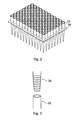
- FIG 2 is a perspective view of a pipette tip tray 34 loaded with pipette tips 22.
- the pipette tips 22 are loaded into trays to allow robotic handling.
- Each tray is a flat piece of stiff material, such as metal or plastic, with an array of through holes in a grid conforming to the desired well plate standard grid, the through holes having a diameter equal to part of the tapered neck portion of the pipette tips 22, so that pipette tips 22 seat in the through holes.
- the head is provided with an array of pipette tip receiving cones 24 with the array being conformant to the well plate type being processed, for example a 12 x 8 array for 96-well well plates.
- FIG. 3 shows a single pipette tip cone 24 together with an upper end of a pipette tip 22.
- Each cone 24 has a central capillary leading to a reservoir formed by a barrel and piston, in which the piston is slidable up and down in the barrel to provide a syringing action.
- the outer surfaces of the cones 24 are corrugated to assist pipette gripping.
- the cones are made of resilient material to aid formation of a liquid tight seal between themselves and the pipette tips 22 they are designed to receive.
- a pipette tip tray anvil 32 arranged on the main bed 18 of the apparatus there can be seen a pipette tip tray anvil 32.
- the anvil 32 is a plate with an array of through holes in a grid conforming to one of the well plate standard grids, the through holes having a diameter slightly larger than the outer diameter of the widest part of the pipette tips 22.
- a number of trays 34 loaded with unused pipette tips 22 are held in a shelved storage rack 36, sometimes referred to as a "hotel" in the art, with each tray arranged on one shelf and vertically adjacent shelves spaced far enough apart to avoid the pipette tips fouling each other when they are slid in and out of the shelves.
- the hotel is illustrated as having three racks, each with three shelves. A greater number of shelves would usually be provided in practice.
- the action of loading pipette tips 22 onto the liquid handling head 10 is now described.
- the head 10 is moved over to the pipette tip tray storage rack 36 and, using the pincers 25, one of the pipette tip trays 34 is taken out and placed on the anvil 32.
- the head 10 is then moved so that the array of cones 24 is aligned above the array of pipette tips 22.
- the head 10 is then driven down so that the (male) cones 24 mate with the (female) upper apertures of the pipette tips 22, the anvil 32 acting as an abutment surface to allow the pipette tips 22 to be pushed onto the cones 24.
- the head 10 is then raised away from the anvil 32 using the z-positioner 16 with each of the cones 24 now loaded with a pipette tip 22 ready for liquid handling.
- the head 10 includes a slotted plate (not shown), immediately above the cones 24 with the slots having a width greater than the maximum outer diameter of the cones and less than the maximum outer diameter of the pipette tips 22.
- the slotted plate is hinged to the main body of the liquid handling head 10. The hinging action allows ejection of pipette tips 22 from the cones 24 on which they are seated.
- the hinged slotted plate is actuated by a lever acting on the slotted plate being pushed onto the stripping posts 21 as the head 10 is driven down over the waste chute 20. The pipette tips are thus stripped off over the waste chute 20.
- liquid handling robot is not capable of performing other actions, such as gridding or picking, which necessitates transfer of the well plates to another machine if these actions need to be performed before or after the liquid handling actions. Each such transfer, carries a contamination risk, and is also inconvenient.
- EP 0 801 309 discloses a pipetting apparatus that employs an automatically releasable pipette head. Spare heads can be stowed in a stowing device when they are not in use. The heads are released at, or picked up from, the stowing device using a releasable chuck mechanism.
- US 2002/051737 discloses a sample ejection device having a head part that can be manually removed as a single unit. This allows a user to swap heads.
- a robot for handling biological sample containers comprising: a head for carrying out processes on biological sample containers; a positioning apparatus for moving the head around the robot; and a parking station for parking the head, wherein the head is connected to the positioning apparatus by an attachment mechanism drivable between a clamped state, in which the head is secured to the positioning apparatus, and a released state, in which the head can be detached from the positioning apparatus and deposited in the park station and wherein the attachment mechanism includes a communication feed-through, and each head has resident logic that allows the robot through the communication feed-through to receive identification data from any head that is attached to the positioning apparatus.
- the park station preferably comprises a plurality of parking bays, each for parking one head. This allows different types of head to be stored ready for action, and also spare heads of the same type in case the head being used suffers a failure.
- the robot will typically be provided with multiple heads, for example two or more liquid handling heads, a mixture of liquid handling and pin heads, or two or more pin heads, thereby providing a flexible multi-purpose robot, capable of carrying out a variety of liquid handling, spotting, gridding and colony picking tasks.
- the attachment mechanism comprises a piston assembly arranged to actuate a knee joint connected to a latch, the knee joint adopting a bent position in the released state and straightened position in the clamped state.
- the piston assembly may advantageously include two piston cylinder units arranged in a push-me-pull-you configuration either side of the knee joint.
- the communication feed-through comprises an electrical contact pad on the head mated with a corresponding contact pad on the robot, thereby to provide communication lines from the robot to the logic resident in the head.
- the contact pad may further provide the head with electrical power feeds.
- a releasable head for a biological sample container handling robot comprising: a communication feed-through for communicating to a robot to which the head is attached; and logic resident in the head that allows communication of head identification data through the communication feed-through to the robot so that the robot can interrogate the head to receive the identification data and thus determine the head's identity.
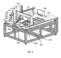
- FIG 4 is a perspective view of a liquid handling robot according to an embodiment of the invention.
- the robot comprises a movable head 110 that is used for liquid handling and also has a mechanical manipulation capability.
- the head 110 is movable in three orthogonal axes, x, y and z, with respective motor positioners 112, 114 and 116. Head motion is controlled by a computer control system (not shown).
- the head 110 may also incorporates a camera (not shown) used to perform machine vision functions, such as bar code reading of well plates.
- the head 110 is movable over a main bed 118 of the apparatus on which well plates and other biological sample containers, such as Q-trays, petri dishes and omni-trays, can be arranged as well as other items such as vacuum manifolds 102 and shakers 104 for processing well plates. Adjacent to the vacuum manifolds 102 and shakers 104 there is a general processing area 105 where well plates, liquid reservoirs and other containers can be arranged for conducting experiments.
- the main bed of the apparatus is supported at a convenient height on a table frame 106.
- a waste chute 120 is incorporated in the main bed 118 and is flanked by stripping arm posts (not visible).
- a well plate storage rack 108 Situated on the far side of the main bed 118 there is a well plate storage rack 108 with four shelf stacks arranged side by side. A slidable cover for the well plate storage rack is also illustrated. Well plates can be taken out of the storage rack 108 by the head 110 using gripping jaws (not visible).
- the robot has the capability of automatically changing between different heads.
- the available heads for the particular robot configuration can be parked in bays 210 within a park station 200.
- Two parking bays 210 are shown in the illustrated park station 200. These are for two different liquid handling heads, a large volume item (up to 250 microliters per pipette) and a small volume item (1-50 microliters per pipette). In other embodiments, three, four or more bays could be provided.
- pin heads for colony picking or spotting or gridding could be provided depending on the robot configuration that is desired. The head swapping functionality and associated equipment is described in detail further below with reference to Figures 7 to 9.
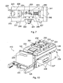
- Figures 5 and 6 are perspective views from different angles of a liquid handling head 110 for pipetting up to 250 ml per pipette.
- the head 110 includes clamping slots 148 arranged to receive the flippers of an anvil apparatus.
- the head 110 is provided with pincers 125 which are used to grip pipette tip trays.
- the pincers 125 are driven by a motor drive 151. Using the pincers 125 and the robot's x-, y- and z-positioners, the head 110 can be used to move pipette tip trays around the apparatus as required.
- the head 110 is also provided with jaws (not shown) for gripping well plates or other sample plates such as omni-trays Q-trays or petri dishes. The jaws are arranged on the opposite side of the head 110 to the pincers 125.
- the head 110 is provided with an array of pipette tip receiving cones 124, one of which is illustrated in Figure 6.
- the cones 124 are arranged in an array that is conformant to the well plate type being processed, which in this example is a 12 x 8 array for 96-well well plates.
- a single pipette tip 122 is also shown in Figure 6 for illustration purposes.
- Each cone 124 is as illustrated in Figure 3 with a central capillary leading to a reservoir formed by a barrel and piston, in which the piston is slidable up and down in the barrel to provide a syringing action.
- the reservoirs are located in the interior of the main body 155 of the head 110.
- the outer surfaces of the cones 124 are corrugated to assist pipette gripping.
- the cones 124 are made of resilient material to aid formation of a liquid tight seal between themselves and the pipette tips 122.
- the head 110 is secured to the z-positioner via a securing plate 149 on its upper side.
- the securing plate 149 also provides a host for an electrical contact pad 150 which mates with a corresponding contact pad on the z-positioner.
- the contact pad 150 provides the head 110 with electrical power feeds for driving the pincer motors, syringing pistons and other functions and also communication feed-throughs for providing communication lines from the main robot to the logic within the head.
- each head has a unique identifier so that the robot can interrogate the head to receive identification data and thus determine the head's identity, which will not only define the head's handling while installed, but also define its parking bay when the heads need to be exchanged or parked.
- the bottom side of the head 110 has a slotted plate 146 mounted by hinges 153, with the slots 152 being evident in Figure 6.
- the slot width is greater than the maximum outer diameter of the cones 124, but less than the maximum outer diameter of the pipette tips 122. Pipette tips 122 can be stripped from the cones 124, and thus the head 110, by hinging the slotted plate 146.
- the slotted plate 146 is actuated by a stripping arm 147 which is mounted on a pivot 154 and has one end that protrudes beyond the side of the main body of the head and another end that is situated above an edge flange of the slotted plate 146.
- the protruding end of the stripping arm is actuated when the head 110 is moved down over the waste chute 120 and encounters a stripping post, which pivots the stripping arm so that its other end pushes down on the flange of the slotted plate 146 causing hinging of the slotted plate.
- the pipette tips 22 are thus stripped off over the waste chute 120.
- Figure 7 is a side view of the head latching unit 220 that is attached to the z-positioner motor drive and serves to allow different heads to be loaded and unloaded.
- Figure 8 is an exploded perspective view of the head latching mechanism of the head latching unit 220.
- Figure 9 is an exploded perspective view of the head latching unit 220 with the head latching mechanism of Figure 8 partly assembled.
- the head latching unit 220 comprises a housing made of top and bottom plates 243 and 240 and left and right end plates 242 and 241.
- Non-structural side plates 244 are also provided (omitted from Figure 7, but evident in Figure 9).
- the bottom plate 240 is provided on its lower side with locating stubs 227 to assist location of the head latching unit in corresponding holes in the heads.
- the latching mechanism is driven by a push-me-pull-you pneumatic piston assembly comprising a delatch driving piston 250 and a latch driving piston 260 with respective cylinders 226 and 266.
- the cylinders 226 and 266 are rotatably mounted by spigots 252 (see Figure 8) located in blocks 245 (see Figure 9) secured to the base plate 240 in a manner similar to a howitzer.
- the cylinders act on a knee joint 255 connecting to a floating upper joint 257 by an upper link 247.
- the knee joint 255 is also connected to a lower fixed joint 256 by a lower link 248.
- the fixed joint 256 is located in the side plates 246 (only one of which is shown in Figure 8) by a locating pin.
- the knee joint 255 is connected to both pistons 250, 260 by respective connectors 251 assisted by a locating pin 253.
- the knee joint 255 has a pin 253 running through it which fits into a pair of arcuate slots 223 in the side plates 246 retained by a pair of outside circlips 254.
- the floating upper joint 257 also has a pin 253 running through it which fits in a pair of vertical slots 225 in the side plates 246 retained by a pair of outside circlips 254.
- the floating upper joint pin also pivotally mounts a latching arm 222.
- the latching arm 222 extends obliquely down to a non-jointed bend 258 with a hole through which a further pin 253 passes which is retained by outside circlips 254 and fits into an L-shaped slot 224 in the side plates 246.
- the latching arm 22 extends vertically down and then at right angles thereto extends further to form a latch support which bears a latch 221.
- FIG 10 is a perspective view of a liquid handling head 110 showing parts used to secure the head to the head securing unit.
- the liquid handling head illustrated is one for pipetting volumes of 1-50 microliters per pipette, in contrast to the larger volume pipetting provided by the liquid handling head illustrated in Figures 5 and 6.
- the latching components of all heads will be similar.
- Figure 10 also shows upper and lower subassemblies 235 and 234 respectively.
- the lower subassembly 234 has ramps 236 on its upper surface on which ride wheels 237 that are carried by the upper subassembly 235. Riding up and down the ramps changes the separation between the subassemblies 235 and 234 and is the movement that provides the syringing action, the reservoir pistons being carried by the upper subassembly 235 and the reservoir cylinders being part of the lower subassembly 234.
- the motion is driven by an electric motor carried in the head.
- FIG. 7-9 illustrate the mechanism in the latched position. In view of this, movement of the mechanism from the latched position to the delatched position is described. This is the movement that would be performed when a head had been returned to its parking bay and was to be released by the head latching unit to allow the z-positioner with head latching unit to be moved away to pick up a different head.
- the delatching piston 250 is pneumatically actuated by compressed air through a feed line (not shown) which pushes the knee joint 255 to the right (as viewed in the figures) which pushes the pin around the arcuate slot 223.
- the non-jointed bend 258 is also forced vertically down guided by the upright part of the L-shaped slot 224.
- the latch 221 is being moved vertically down, allowing it to become free of the head's latch 230 (assuming the head 110 is supported in its parking bay).
- the latching arm 222 is forced to rotate by the pin through the non-jointed bend 258 being confined to move in the base of the L-shaped slot until it abuts the end of the base section of the L-shaped slot.
- the mechanism is now in the delatched position, with the knee joint 255 at its maximum bend and the latching arm 222 at is maximum swing angle away from vertical, swung into a space 261 provided within the plate 231.
- the latching arm 222 has swung away sufficiently to allow the latching unit 220 to be lifted away from the head 110 by a simple vertical motion of the z-positioner. It will now be appreciated why the piston assemblies are pivotally mounted, namely to accommodate movement of the pins in the slots 223, 224 and 225.
- Motion from the delatched to the latched position proceeds approximately in the reverse sequence. It is initiated by actuation of the latching piston 260 which acts on the knee joint 255 to straighten it out.
- the reverse sequence of slot motion is performed in relation to the latch-to-delatch motion with the latching arm 222 being forced to move vertically upward in the L-shaped slot 224 when the pin through the non-jointed bend 258 reaches the corner of the L-shaped slot 224.
- the design allows a high amount of clamping force to be exerted, with the head's latch 230 being squeezed between the latching unit's latch 221 and the bottom of the lower link 248. This feature provides a highly secure latching of the head.
- Figure 11 shows the low volume liquid handling head 110 attached to the head securing unit 220 with the latching mechanism in the latched position described above.
Landscapes
- Chemical & Material Sciences (AREA)
- Health & Medical Sciences (AREA)
- Immunology (AREA)
- General Physics & Mathematics (AREA)
- Pathology (AREA)
- Clinical Laboratory Science (AREA)
- Physics & Mathematics (AREA)
- Life Sciences & Earth Sciences (AREA)
- Analytical Chemistry (AREA)
- Biochemistry (AREA)
- General Health & Medical Sciences (AREA)
- Chemical Kinetics & Catalysis (AREA)
- Robotics (AREA)
- Engineering & Computer Science (AREA)
- Automatic Analysis And Handling Materials Therefor (AREA)
- Sampling And Sample Adjustment (AREA)
- Automobile Manufacture Line, Endless Track Vehicle, Trailer (AREA)
- Manipulator (AREA)
- Coating Apparatus (AREA)
Claims (15)
- Robot pour la manipulation de récipients d'échantillons biologiques, comportant :
une tête (110) destinée à exécuter des traitements sur des récipients d'échantillons biologiques ;
un appareil de positionnement destiné à déplacer la tête (110) autour du robot; et
un poste (200) de stationnement pour le stationnement de la tête,
dans lequel la tête est reliée à l'appareil de positionnement par un mécanisme d'attache pouvant être entraîné entre un état serré, dans lequel la tête est fixée à l'appareil de positionnement, et un état libéré, dans lequel la tête peut être détachée de l'appareil de positionnement et déposée dans le poste de stationnement,
et caractérisé en ce que le mécanisme d'attache comprend une traversée de communication, et chaque tête possède une logique résidente qui permet au robot, par la traversée de communication, de recevoir des données d'identification provenant de n'importe quelle tête (110) qui est attachée à l'appareil de positionnement. - Robot selon la revendication 1, dans lequel le poste de stationnement (200) comporte une pluralité de travées (210) de stationnement, chacune pour le stationnement d'une tête (110).
- Robot selon la revendication 2, comportant une autre tête (110).
- Robot selon la revendication 3, dans lequel la tête (110) et l'autre tête (110) sont toutes deux des têtes de manipulation de liquide.
- Robot selon la revendication 3, dans lequel la tête (110) est une tête de manipulation de liquide et l'autre tête (110) est une tête à épingles.
- Robot selon la revendication 3, dans lequel la tête (110) et l'autre tête (110) sont toutes deux des têtes à épingles.
- Robot selon l'une quelconque des revendications 1 à 6, dans lequel le mécanisme d'attache comporte un ensemble à piston agencé de façon à actionner une articulation à genouillère (255) reliée à un verrou, l'articulation à genouillère adoptant une position pliée dans l'état libéré et une position redressée dans l'état serré.
- Robot selon la revendication 7, dans lequel l'ensemble à piston comprend deux unités à cylindres et pistons (250, 260) agencées dans une configuration en tandem de chaque côté de l'articulation à genouillère.
- Robot selon l'une quelconque des revendications précédentes, dans lequel la traversée de communication comporte un plot de contact électrique (150) sur la tête (110) accouplée avec un plot de contact correspondant sur le robot, afin d'établir des lignes de communication du robot à la logique résidente dans la tête.
- Robot selon la revendication 9, dans lequel le plot de contact (150) procure en outre à la tête (110) des alimentations en énergie électrique.
- Tête libérable (110) pour un robot de manipulation de récipients d'échantillons biologiques, comportant :une traversée de communication pour une communication avec un robot auquel la tête (110) est attachée ; etune logique résidente dans la tête qui permet une communication de données d'identification de tête par la traversée de communication au robot afin que le robot puisse interroger la tête pour recevoir les données d'identification et déterminer ainsi l'identité de la tête.
- Tête (110) selon la revendication 11, dans laquelle la traversée de communication comporte un plot de contact électrique (150) pouvant être mis en oeuvre pour s'accoupler avec un plot de contact correspondant sur le robot, établissant ainsi des lignes de communication du robot à la logique résidente dans la tête.
- Tête selon la revendication 12, dans laquelle le plot de contact (150) procure en outre à la tête (110) des alimentations en énergie électrique.
- Tête (110) selon la revendication 11, 12 ou 13, laquelle tête est une tête de manipulation de liquide.
- Tête (110) selon la revendication 11, 12 ou 13, laquelle tête est une tête à épingles.
Applications Claiming Priority (2)
| Application Number | Priority Date | Filing Date | Title |
|---|---|---|---|
| US10/144,763 US7105129B2 (en) | 2002-05-15 | 2002-05-15 | Liquid handling robot for well plates |
| EP03252361A EP1366822B1 (fr) | 2002-05-15 | 2003-04-14 | Robot de manipulation des liquides pour plaques a puits |
Related Parent Applications (1)
| Application Number | Title | Priority Date | Filing Date |
|---|---|---|---|
| EP03252361A Division EP1366822B1 (fr) | 2002-05-15 | 2003-04-14 | Robot de manipulation des liquides pour plaques a puits |
Publications (3)
| Publication Number | Publication Date |
|---|---|
| EP1627687A2 EP1627687A2 (fr) | 2006-02-22 |
| EP1627687A3 EP1627687A3 (fr) | 2006-08-09 |
| EP1627687B1 true EP1627687B1 (fr) | 2008-01-02 |
Family
ID=29418539
Family Applications (2)
| Application Number | Title | Priority Date | Filing Date |
|---|---|---|---|
| EP03252361A Expired - Lifetime EP1366822B1 (fr) | 2002-05-15 | 2003-04-14 | Robot de manipulation des liquides pour plaques a puits |
| EP05016744A Revoked EP1627687B1 (fr) | 2002-05-15 | 2003-04-14 | Robot de manipulation des récipients d'échantillons biologiques |
Family Applications Before (1)
| Application Number | Title | Priority Date | Filing Date |
|---|---|---|---|
| EP03252361A Expired - Lifetime EP1366822B1 (fr) | 2002-05-15 | 2003-04-14 | Robot de manipulation des liquides pour plaques a puits |
Country Status (4)
| Country | Link |
|---|---|
| US (2) | US7105129B2 (fr) |
| EP (2) | EP1366822B1 (fr) |
| AT (1) | ATE303206T1 (fr) |
| DE (2) | DE60301435T2 (fr) |
Families Citing this family (59)
| Publication number | Priority date | Publication date | Assignee | Title |
|---|---|---|---|---|
| US20030054543A1 (en) * | 1997-06-16 | 2003-03-20 | Lafferty William Michael | Device for moving a selected station of a holding plate to a predetermined location for interaction with a probe |
| US7452712B2 (en) | 2002-07-30 | 2008-11-18 | Applied Biosystems Inc. | Sample block apparatus and method of maintaining a microcard on a sample block |
| US7247429B2 (en) * | 2002-08-07 | 2007-07-24 | Genetix Limited | Biochemical amplification of nucleic acids |
| JP3733942B2 (ja) * | 2002-10-03 | 2006-01-11 | 松下電器産業株式会社 | 分注装置および分注装置における分注ティップの離脱方法 |
| US7118708B2 (en) * | 2002-11-12 | 2006-10-10 | Automated Biotechnology, Inc. | System of sample medium carriers with built-in memory elements and information input/output station for the carriers |
| US7584019B2 (en) * | 2003-12-15 | 2009-09-01 | Dako Denmark A/S | Systems and methods for the automated pre-treatment and processing of biological samples |
| CA2521539A1 (fr) * | 2003-04-08 | 2004-10-28 | Irm, Llc | Dispositifs, systemes et procedes de retrait et de distribution de matieres |
| US7776584B2 (en) | 2003-08-01 | 2010-08-17 | Genetix Limited | Animal cell colony picking apparatus and method |
| US20070015289A1 (en) * | 2003-09-19 | 2007-01-18 | Kao H P | Dispenser array spotting |
| US20050226779A1 (en) * | 2003-09-19 | 2005-10-13 | Oldham Mark F | Vacuum assist for a microplate |
| US20050221358A1 (en) * | 2003-09-19 | 2005-10-06 | Carrillo Albert L | Pressure chamber clamp mechanism |
| GB0328887D0 (en) * | 2003-12-12 | 2004-01-14 | Glaxo Group Ltd | Object holding tool and object supporting unit |
| GB0328901D0 (en) * | 2003-12-12 | 2004-01-14 | Glaxo Group Ltd | Object handling system & method |
| DE102004057450B4 (de) * | 2004-11-24 | 2013-07-25 | Cybio Ag | Automatisches Pipetier- und Analysegerät |
| DE102005049920A1 (de) * | 2005-10-17 | 2007-04-19 | Manz Automation Ag | Roboteranordnung |
| US8192698B2 (en) * | 2006-01-27 | 2012-06-05 | Parker-Hannifin Corporation | Sampling probe, gripper and interface for laboratory sample management systems |
| GB0717462D0 (en) * | 2007-09-07 | 2007-10-17 | Mole Genetics As | Liquid delivery apparatus |
| GB0717461D0 (en) * | 2007-09-07 | 2007-10-17 | Mole Genetics As | Separation apparatus |
| JP5470369B2 (ja) | 2008-04-11 | 2014-04-16 | バイオティクス, インコーポレイテッド | ピペットチップを取り扱うデバイスおよび方法 |
| DE102008018982A1 (de) | 2008-04-14 | 2009-11-05 | Merz, Hartmut, Prof. Dr. med. | Automatische Vorrichtung zur Durchführung von Nachweisreaktionen und Verfahren zur Dosierung von Reagenzien auf Objektträgern |
| ITFI20080101A1 (it) * | 2008-05-21 | 2009-11-22 | Esposti Filippo Degli | Dispositivo per il cambio automatico di un utensile per autocampionatori |
| US8007741B1 (en) * | 2008-07-08 | 2011-08-30 | Scigene Corporation | Pipetting head with plate gripper |
| CA2750376C (fr) | 2009-01-23 | 2016-12-13 | Biotix, Inc. | Plateaux d'embout de pipette antistatiques |
| US8590736B2 (en) * | 2009-04-11 | 2013-11-26 | Biotix, Inc. | Automated pipette tip loading devices and methods |
| EP2585834B1 (fr) | 2010-06-28 | 2017-12-20 | Life Technologies Corporation | Systèmes et procédés de transfert d'échantillons liquides |
| US9696332B2 (en) * | 2010-07-23 | 2017-07-04 | Matrix Technologies Llc | Automated liquid handling device |
| CN108761108B (zh) | 2010-11-23 | 2022-06-07 | 安德鲁联合有限公司 | 容积校准、处理流体和操纵移液管的方法 |
| CN103608672B (zh) | 2011-06-09 | 2017-07-28 | 安捷伦科技有限公司 | 带有可拆卸式注射针的样品注射器 |
| US9733221B2 (en) | 2011-06-09 | 2017-08-15 | Agilent Technologies, Inc. | Injection needle cartridge with integrated sealing force generator |
| ITMI20120975A1 (it) | 2012-06-05 | 2013-12-06 | Inpeco Ip Ltd | Apparato di interfacciamento tra un impianto di automazione di laboratorio e una piattaforma per la movimentazione di consumabili e liquidi nell'ambito della biologia molecolare. |
| EP2703820B1 (fr) * | 2012-08-31 | 2019-08-28 | F. Hoffmann-La Roche AG | Panier de déchets à pointe mobile |
| TWI481804B (zh) * | 2012-10-03 | 2015-04-21 | Wei Hua Chaing | 瓶裝藥劑製程之自動化取送料軌道搬運車 |
| GB201316644D0 (en) | 2013-09-19 | 2013-11-06 | Kymab Ltd | Expression vector production & High-Throughput cell screening |
| CN103592446B (zh) * | 2013-10-22 | 2015-09-02 | 中国科学院苏州生物医学工程技术研究所 | 一种全自动化学发光免疫分析仪用针头装载托盘 |
| US10493457B2 (en) * | 2014-03-28 | 2019-12-03 | Brooks Automation, Inc. | Sample storage and retrieval system |
| USD865216S1 (en) | 2014-12-10 | 2019-10-29 | Biotix, Inc. | Pipette tip sheet |
| US10730053B2 (en) | 2014-12-10 | 2020-08-04 | Biotix, Inc. | Static-defeating apparatus for pipette tips |
| US10137453B2 (en) | 2014-12-10 | 2018-11-27 | Biotix, Inc. | Static-defeating apparatus for pipette tips |
| USD849962S1 (en) | 2014-12-10 | 2019-05-28 | Biotix, Inc. | Pipette tip retention sheet |
| USD815753S1 (en) | 2014-12-10 | 2018-04-17 | Biotix, Inc. | Pipette tip sheet |
| CN106554901B (zh) * | 2015-09-30 | 2019-06-14 | 精专生医股份有限公司 | 自动化萃取核酸的机台及配合其使用的针筒 |
| NZ742318A (en) * | 2015-10-29 | 2019-10-25 | Vibrant Holdings Llc | Methods, tools, and tool assemblies for biomolecular analysis using microarrays |
| CN107914287A (zh) * | 2016-10-09 | 2018-04-17 | 张家港市博雅文化传播有限公司 | 一种运载机器人升降机构 |
| US10864515B2 (en) * | 2016-11-11 | 2020-12-15 | Walid Habbal | Automated pipette manipulation system |
| JP7019303B2 (ja) * | 2017-03-24 | 2022-02-15 | 東芝テック株式会社 | 液滴分注装置 |
| WO2018191534A1 (fr) * | 2017-04-14 | 2018-10-18 | Aviva Biosciences Corporation | Procédés, compositions et dispositifs permettant de séparer et/ou d'enrichir des cellules |
| EP3400962A1 (fr) | 2017-05-09 | 2018-11-14 | Fraunhofer Gesellschaft zur Förderung der angewandten Forschung e.V. | Inhibiteurs de l'il-38 destinés à être utilisés dans le traitement et/ou la prévention du cancer chez un sujet |
| KR20200015629A (ko) * | 2017-06-02 | 2020-02-12 | 프라운호퍼-게젤샤프트 추르 푀르데룽 데어 안제반텐 포르슝 에 파우 | 식물 세포 팩의 자동 형질전환 방법 |
| WO2019017726A2 (fr) | 2017-07-21 | 2019-01-24 | Seegene, Inc. | Modules de transfert de billes magnétiques, système automatisé les comprenant et procédé d'extraction d'acides nucléiques l'utilisant |
| WO2019108693A1 (fr) * | 2017-11-30 | 2019-06-06 | Corning Incorporated | Pipette thermoplastique à orientation biaxiale, procédé et appareil de formation de celle-ci |
| CN108296213A (zh) * | 2017-12-26 | 2018-07-20 | 深圳德夏科技发展有限公司 | 洗板机 |
| ES2911471T3 (es) * | 2018-12-14 | 2022-05-19 | Eppendorf Ag | Aparato automático de laboratorio para el tratamiento automático de muestras de laboratorio |
| CN109807106A (zh) * | 2019-03-21 | 2019-05-28 | 安图实验仪器(郑州)有限公司 | 全自动托盘式玻片震荡清洗机构 |
| CN116323105A (zh) * | 2020-07-31 | 2023-06-23 | 武田药品工业株式会社 | 用于液体搬运机器人的抓取检测系统 |
| KR102459226B1 (ko) * | 2021-03-30 | 2022-10-27 | 한국기계연구원 | 마이크로 스케일 적층 가공을 이용한 웰플레이트 제조 및 용액 분주 장치와, 이를 이용한 웰플레이트 제조 및 용액 분주 방법 |
| CN113856786B (zh) * | 2021-10-29 | 2022-10-11 | 江苏睿玻生物科技有限公司 | 枪头的自动运输组件、自动运输方法以及移液系统 |
| CN114733589A (zh) * | 2022-03-03 | 2022-07-12 | 济南市疾病预防控制中心 | 一种自动移液站 |
| CN114799788B (zh) * | 2022-03-30 | 2024-02-23 | 厦门立洲五金弹簧有限公司 | 一种机械零部件加工用具有精准抓取结构的组装装置 |
| CN115445685A (zh) * | 2022-09-09 | 2022-12-09 | 深圳鸣基医疗科技有限公司 | 用于统一移液枪头长度的辅助装置及方法 |
Family Cites Families (14)
| Publication number | Priority date | Publication date | Assignee | Title |
|---|---|---|---|---|
| US3650306A (en) * | 1970-09-18 | 1972-03-21 | Cooke Eng Co | Laboratory dispensing apparatus |
| US5206568A (en) | 1986-03-26 | 1993-04-27 | Beckman Instruments, Inc. | Coordinated control of stepper motors |
| US5139744A (en) | 1986-03-26 | 1992-08-18 | Beckman Instruments, Inc. | Automated laboratory work station having module identification means |
| JPH0656384B2 (ja) * | 1987-08-31 | 1994-07-27 | 株式会社東芝 | ピペットチップ装着機構 |
| DE9421735U1 (de) | 1994-09-08 | 1996-07-11 | Steinbrenner Bernd Dr | Vorrichtung zur Bereitstellung einer Vielzahl von Gegenständen auf einem Träger |
| DE59707862D1 (de) | 1996-03-07 | 2002-09-05 | Greiner Bio One Gmbh Kremsmuen | Aufnahmebehälter für stapelbare verbrauchseinheiten |
| EP0801309A3 (fr) * | 1996-04-08 | 1998-08-12 | SANYO ELECTRIC Co., Ltd. | Dispositif de pipettage |
| US6116099A (en) | 1996-11-18 | 2000-09-12 | Carl; Richard A. | Liquid dispensing apparatus having means for loading pipette tips onto fluid dispensing cylinders |
| JP3584732B2 (ja) | 1998-05-08 | 2004-11-04 | 松下電器産業株式会社 | 分注装置および分注方法ならびに分注チップの装着方法 |
| US20010046437A1 (en) | 1998-09-23 | 2001-11-29 | Bramwell A. Mark | Automated system for storing or dispensing stackable goods |
| US6544480B1 (en) * | 1999-10-26 | 2003-04-08 | Tibotec Bvba | Device and related method for dispensing small volumes of liquid |
| US6325114B1 (en) | 2000-02-01 | 2001-12-04 | Incyte Genomics, Inc. | Pipetting station apparatus |
| EP1275966B1 (fr) | 2000-03-15 | 2006-07-12 | Hitachi, Ltd. | Analyseur automatique et dispositif d'alimentation en pieces servant a l'analyseur |
| DE20018628U1 (de) | 2000-11-01 | 2002-03-14 | Evotec Biosystems Ag | Probenabgabevorrichtung |
-
2002
- 2002-05-15 US US10/144,763 patent/US7105129B2/en not_active Expired - Lifetime
-
2003
- 2003-04-14 EP EP03252361A patent/EP1366822B1/fr not_active Expired - Lifetime
- 2003-04-14 DE DE60301435T patent/DE60301435T2/de not_active Expired - Lifetime
- 2003-04-14 AT AT03252361T patent/ATE303206T1/de not_active IP Right Cessation
- 2003-04-14 EP EP05016744A patent/EP1627687B1/fr not_active Revoked
- 2003-04-14 DE DE60318498T patent/DE60318498T2/de not_active Revoked
-
2006
- 2006-08-04 US US11/498,839 patent/US7628960B2/en not_active Expired - Fee Related
Also Published As
| Publication number | Publication date |
|---|---|
| DE60301435D1 (de) | 2005-10-06 |
| EP1627687A2 (fr) | 2006-02-22 |
| US7105129B2 (en) | 2006-09-12 |
| DE60318498D1 (de) | 2008-02-14 |
| EP1366822A2 (fr) | 2003-12-03 |
| EP1366822A3 (fr) | 2004-01-14 |
| ATE303206T1 (de) | 2005-09-15 |
| EP1366822B1 (fr) | 2005-08-31 |
| DE60318498T2 (de) | 2008-12-11 |
| US20060269447A1 (en) | 2006-11-30 |
| US20030215360A1 (en) | 2003-11-20 |
| DE60301435T2 (de) | 2006-06-14 |
| US7628960B2 (en) | 2009-12-08 |
| EP1627687A3 (fr) | 2006-08-09 |
Similar Documents
| Publication | Publication Date | Title |
|---|---|---|
| EP1627687B1 (fr) | Robot de manipulation des récipients d'échantillons biologiques | |
| EP2008112B1 (fr) | Station d'accueil d'instruments pour un système d'essai automatisé | |
| US8865474B2 (en) | Automated laboratory system | |
| US7988912B2 (en) | Robotic grip and twist assembly | |
| US6116099A (en) | Liquid dispensing apparatus having means for loading pipette tips onto fluid dispensing cylinders | |
| US4852242A (en) | Tool coupling apparatus and method | |
| US20040101966A1 (en) | Sealed sample storage element system and method | |
| EP2831596A1 (fr) | Éléments de laboratoire et systèmes de manipulation de liquides, et leurs procédés d'utilisation | |
| WO2002096562B1 (fr) | Systeme de pipetage automatise | |
| CN112379243B (zh) | 一种电路板常温测试自动上下料与插拔系统及方法 | |
| EP1720016A2 (fr) | Procédé et dispositif de fabrication des microreseaux | |
| US20140273268A1 (en) | Preparation of samples for analysis | |
| CN111440703A (zh) | 一种双提取模式核酸提取工作站及核酸提取方法 | |
| JP3299212B2 (ja) | 液の転写部材及び転写装置 | |
| CN109016343A (zh) | 机械手、机器人及镶件设备 | |
| CN115674278A (zh) | 手套箱系统 | |
| WO1997010055A1 (fr) | Tubulure a vide pour le traitement en laboratoire d'echantillons liquides multiples | |
| WO1997010055A9 (fr) | Tubulure a vide pour le traitement en laboratoire d'echantillons liquides multiples | |
| JPS62502224A (ja) | 電気コネクタ移送用収容室 | |
| CN117607474A (zh) | 一种全自动分杯系统 | |
| CN216419445U (zh) | 一种用于移液工作台的限位装置 | |
| CN212099655U (zh) | 一种移液枪的枪头批量装盒系统 | |
| CN113290383A (zh) | 机箱配件前加工线和机箱组装产线 | |
| CN213230498U (zh) | 一种出料装置和出料生产线 | |
| CN217359203U (zh) | 液基样本处理设备 |
Legal Events
| Date | Code | Title | Description |
|---|---|---|---|
| PUAI | Public reference made under article 153(3) epc to a published international application that has entered the european phase |
Free format text: ORIGINAL CODE: 0009012 |
|
| 17P | Request for examination filed |
Effective date: 20050818 |
|
| AC | Divisional application: reference to earlier application |
Ref document number: 1366822 Country of ref document: EP Kind code of ref document: P |
|
| AK | Designated contracting states |
Kind code of ref document: A2 Designated state(s): AT BE BG CH CY CZ DE DK EE ES FI FR GB GR HU IE IT LI LU MC NL PT RO SE SI SK TR |
|
| AX | Request for extension of the european patent |
Extension state: AL LT LV MK |
|
| PUAL | Search report despatched |
Free format text: ORIGINAL CODE: 0009013 |
|
| AK | Designated contracting states |
Kind code of ref document: A3 Designated state(s): AT BE BG CH CY CZ DE DK EE ES FI FR GB GR HU IE IT LI LU MC NL PT RO SE SI SK TR |
|
| AX | Request for extension of the european patent |
Extension state: AL LT LV MK |
|
| AKX | Designation fees paid |
Designated state(s): CH DE FR GB LI |
|
| GRAP | Despatch of communication of intention to grant a patent |
Free format text: ORIGINAL CODE: EPIDOSNIGR1 |
|
| RTI1 | Title (correction) |
Free format text: ROBOT FOR HANDLING BIOLOGICAL SAMPLE CONTAINERS. |
|
| GRAS | Grant fee paid |
Free format text: ORIGINAL CODE: EPIDOSNIGR3 |
|
| GRAA | (expected) grant |
Free format text: ORIGINAL CODE: 0009210 |
|
| AC | Divisional application: reference to earlier application |
Ref document number: 1366822 Country of ref document: EP Kind code of ref document: P |
|
| AK | Designated contracting states |
Kind code of ref document: B1 Designated state(s): CH DE FR GB LI |
|
| REG | Reference to a national code |
Ref country code: GB Ref legal event code: FG4D |
|
| REG | Reference to a national code |
Ref country code: CH Ref legal event code: EP Ref country code: CH Ref legal event code: NV Representative=s name: MICHELI & CIE SA |
|
| REF | Corresponds to: |
Ref document number: 60318498 Country of ref document: DE Date of ref document: 20080214 Kind code of ref document: P |
|
| ET | Fr: translation filed | ||
| PLBI | Opposition filed |
Free format text: ORIGINAL CODE: 0009260 |
|
| PLAX | Notice of opposition and request to file observation + time limit sent |
Free format text: ORIGINAL CODE: EPIDOSNOBS2 |
|
| 26 | Opposition filed |
Opponent name: EPPENDORF - NETHELER - HINZ GMBH Effective date: 20081002 |
|
| PLBB | Reply of patent proprietor to notice(s) of opposition received |
Free format text: ORIGINAL CODE: EPIDOSNOBS3 |
|
| PGFP | Annual fee paid to national office [announced via postgrant information from national office to epo] |
Ref country code: CH Payment date: 20100311 Year of fee payment: 8 |
|
| RDAF | Communication despatched that patent is revoked |
Free format text: ORIGINAL CODE: EPIDOSNREV1 |
|
| PGFP | Annual fee paid to national office [announced via postgrant information from national office to epo] |
Ref country code: FR Payment date: 20100325 Year of fee payment: 8 |
|
| PGFP | Annual fee paid to national office [announced via postgrant information from national office to epo] |
Ref country code: GB Payment date: 20100311 Year of fee payment: 8 |
|
| PGFP | Annual fee paid to national office [announced via postgrant information from national office to epo] |
Ref country code: DE Payment date: 20100610 Year of fee payment: 8 |
|
| RDAG | Patent revoked |
Free format text: ORIGINAL CODE: 0009271 |
|
| REG | Reference to a national code |
Ref country code: CH Ref legal event code: PL |
|
| RDAC | Information related to revocation of patent modified |
Free format text: ORIGINAL CODE: 0009299REVO |
|
| STAA | Information on the status of an ep patent application or granted ep patent |
Free format text: STATUS: PATENT REVOKED |
|
| 27W | Patent revoked |
Effective date: 20100120 |
|
| GBPR | Gb: patent revoked under art. 102 of the ep convention designating the uk as contracting state |
Effective date: 20100120 |
|
| R27W | Patent revoked (corrected) |
Effective date: 20100119 |
|
| PG25 | Lapsed in a contracting state [announced via postgrant information from national office to epo] |
Ref country code: CH Free format text: LAPSE BECAUSE OF THE APPLICANT RENOUNCES Effective date: 20080102 Ref country code: LI Free format text: LAPSE BECAUSE OF THE APPLICANT RENOUNCES Effective date: 20080102 |