EP1625810A1 - Dispositif amortisseur de mouvement - Google Patents
Dispositif amortisseur de mouvement Download PDFInfo
- Publication number
- EP1625810A1 EP1625810A1 EP05016336A EP05016336A EP1625810A1 EP 1625810 A1 EP1625810 A1 EP 1625810A1 EP 05016336 A EP05016336 A EP 05016336A EP 05016336 A EP05016336 A EP 05016336A EP 1625810 A1 EP1625810 A1 EP 1625810A1
- Authority
- EP
- European Patent Office
- Prior art keywords
- retaining
- piston rod
- damper housing
- damping device
- retaining element
- Prior art date
- Legal status (The legal status is an assumption and is not a legal conclusion. Google has not performed a legal analysis and makes no representation as to the accuracy of the status listed.)
- Granted
Links
- 238000013016 damping Methods 0.000 title claims description 66
- 210000000078 claw Anatomy 0.000 claims description 76
- 238000003780 insertion Methods 0.000 claims description 48
- 230000037431 insertion Effects 0.000 claims description 48
- 230000000903 blocking effect Effects 0.000 claims description 30
- 230000014759 maintenance of location Effects 0.000 claims description 16
- 230000009471 action Effects 0.000 claims description 6
- 230000002996 emotional effect Effects 0.000 claims 1
- 230000000694 effects Effects 0.000 description 6
- 230000008878 coupling Effects 0.000 description 5
- 238000010168 coupling process Methods 0.000 description 5
- 238000005859 coupling reaction Methods 0.000 description 5
- 239000000463 material Substances 0.000 description 5
- 239000000243 solution Substances 0.000 description 5
- 238000000605 extraction Methods 0.000 description 4
- 239000012530 fluid Substances 0.000 description 4
- 230000000717 retained effect Effects 0.000 description 3
- 230000001154 acute effect Effects 0.000 description 2
- 230000008901 benefit Effects 0.000 description 2
- 238000010276 construction Methods 0.000 description 2
- 230000005489 elastic deformation Effects 0.000 description 2
- 238000002347 injection Methods 0.000 description 2
- 239000007924 injection Substances 0.000 description 2
- 238000003754 machining Methods 0.000 description 2
- 230000007246 mechanism Effects 0.000 description 2
- 239000002184 metal Substances 0.000 description 2
- 238000000034 method Methods 0.000 description 2
- 230000008569 process Effects 0.000 description 2
- TVEXGJYMHHTVKP-UHFFFAOYSA-N 6-oxabicyclo[3.2.1]oct-3-en-7-one Chemical compound C1C2C(=O)OC1C=CC2 TVEXGJYMHHTVKP-UHFFFAOYSA-N 0.000 description 1
- 230000002411 adverse Effects 0.000 description 1
- 230000036461 convulsion Effects 0.000 description 1
- 238000006073 displacement reaction Methods 0.000 description 1
- 230000003993 interaction Effects 0.000 description 1
- 238000004519 manufacturing process Methods 0.000 description 1
- 238000013017 mechanical damping Methods 0.000 description 1
- 239000007769 metal material Substances 0.000 description 1
- 238000005096 rolling process Methods 0.000 description 1
- 230000007480 spreading Effects 0.000 description 1
- 238000003892 spreading Methods 0.000 description 1
Images


Classifications
-
- A—HUMAN NECESSITIES
- A47—FURNITURE; DOMESTIC ARTICLES OR APPLIANCES; COFFEE MILLS; SPICE MILLS; SUCTION CLEANERS IN GENERAL
- A47B—TABLES; DESKS; OFFICE FURNITURE; CABINETS; DRAWERS; GENERAL DETAILS OF FURNITURE
- A47B88/00—Drawers for tables, cabinets or like furniture; Guides for drawers
- A47B88/40—Sliding drawers; Slides or guides therefor
- A47B88/453—Actuated drawers
- A47B88/46—Actuated drawers operated by mechanically-stored energy, e.g. by springs
- A47B88/467—Actuated drawers operated by mechanically-stored energy, e.g. by springs self-closing
-
- A—HUMAN NECESSITIES
- A47—FURNITURE; DOMESTIC ARTICLES OR APPLIANCES; COFFEE MILLS; SPICE MILLS; SUCTION CLEANERS IN GENERAL
- A47B—TABLES; DESKS; OFFICE FURNITURE; CABINETS; DRAWERS; GENERAL DETAILS OF FURNITURE
- A47B2210/00—General construction of drawers, guides and guide devices
- A47B2210/0091—Drawer movement damping
- A47B2210/0094—Drawer damping device with 2 relatively movable parts to convert kinetic energy
Definitions
- the present invention relates to a movement damping device comprising a damper housing, a piston displaceable relative to the damper housing with a piston rod and a retaining device, which prevents the piston rod to follow the movement of the damper housing when the damper housing moves away from the retaining device along its extension direction until the piston rod has been pulled out of the damper housing by a predetermined pull-out distance and then releases the piston rod.
- Such movement damping devices are known from the prior art and, in particular in pull-out guides which comprise at least one first guide rail and a second guide rail which can be displaced relative to the first guide rail, can be used to control the speed of the second guide rail relative to the first guide rail in the first guide rail End phase of the movement of the second guide rail in the insertion position to reduce or at least limit, so that a held on the pullout guide extract moves as gently as possible in the insertion position.
- the effect of the movement damping device is based on the piston having to overcome a resistance force, for example a flow resistance or a frictional resistance, in order to move relative to the damper housing, so that the kinetic energy of the guide rail to be braked is dissipated.
- a resistance force for example a flow resistance or a frictional resistance
- Such a retaining means may for example comprise a piston rod end mounted on the magnet, which is retained on a likewise magnetic or magnetizable stop of the piston rod until the piston rod has been completely pulled out of the damper housing, whereupon the magnet at the piston rod end of the stop of the piston rod dissolves and with the damper housing is moved.
- This solution has the disadvantage that additional components are required and the permanent magnet used is relatively expensive.
- both at the beginning of the extension movement of the damper housing and then also when the detachment of the magnet from the stop of the piston rod an unpleasant jerk occurs because the magnetic attraction must be overcome in a very small displacement.
- a Auszieh Installationsgarnitur with a rail system which includes a fixed carcass rail and a directly or indirectly on a center rail thereon longitudinally displaceably mounted drawer rail, wherein both a damping device as a coupling device between the fixed rail and the linearly movable drawer slide are provided, wherein the damping device includes a cylinder and a linearly movable piston rod damped therein, wherein the cylinder is connected to the movable drawer rail and the piston rod with a first part of the coupling device, which with a second part of the coupling device on the carcass rail temporarily positively and repeatedly releasably cooperates, wherein the first part of the coupling device includes a hook body which is arranged on the free end of the piston rod to a mounting portion, and at least one return hook is arranged at the free end of the hook body , which can be moved elastically resiliently by the action of force of a fixedly connected to the drawer rail control wedge, and wherein the second part of
- the present invention has for its object to provide a movement damping device of the type mentioned above, which allows in a simple and reliable manner a return movement of the piston rod into its initial position relative to the damper housing when pulling the damper housing along the extension direction.
- a motion damping device having the features of the preamble of claim 1 according to the invention that the retaining device comprises at least one retaining element which engages in a retaining position an end portion of the piston rod so that the piston rod is prevented from following the movement of the damper housing , and in a release position allows the end portion of the piston rod passes, and that the motion damping device comprises a locking device with at least one blocking element, which prevents the retaining element from the retaining position moves to the release position until the piston rod pulled out of the damper housing by the predetermined Auszugweg has been, and then releases the movement of the retaining element in the release position.
- the solution according to the invention is thus based on the concept of retaining the piston rod in a stop position by means of positive locking with at least one retaining element of the retaining device until the damper housing has been moved by the predetermined extension travel in the extension direction and thus the piston rod has been pulled out of the damper housing by this withdrawal path.
- the retaining element is prevented by a locking element associated with the blocking element, that is not or at least not exclusively by latching with the piston rod, from it, to release the movement of the piston rod in the extension direction.
- the solution according to the invention has the advantage that the piston rod does not have to carry a movable section at its end region and thus, in particular when using a damper with a cylindrical piston rod, preferably made of metal, by simple, in particular machining, machining can be shaped so that it cooperates with the at least one retaining element, without the attachment of additional parts is required.
- the piston rod may be integrally formed.
- the interaction of the blocking element with the retaining element can basically be of any nature.
- the blocking element prevents by positive engagement with the retaining element, the retaining element on the movement of the retaining position in the release position.
- the movement damping device according to the invention can be used both in pull-outs with self-closing device and in pull-outs without self-closing device.
- Such a self-retracting device engages when the extract has reached a Disksstartwolf on the extract or on a guide rail of an extension guide and moves the extract or the guide rail of the drawer guide automatically in the insertion position.
- the motion damping device preferably comprises at least two retaining elements, wherein in a preferred embodiment of the invention, at least two retaining elements of the retaining means are arranged on opposite sides of the piston rod.
- the retaining device has a tubular construction and comprises a plurality of retaining elements, which are arranged in the retaining position along the circumference of the piston rod.
- the retaining element can be moved in a simple and reliable manner by the piston rod from the retaining position to the free-hold position to allow the piston rod to pass in the direction of insertion, it is provided in a preferred embodiment of the invention that the retaining element a the damper housing facing run-on slope, against which the piston rod starts when it moves in the direction of extension opposite direction of insertion.
- the retaining element has a formula elasticity, by which the retaining element in its rest position, ie occupies the retaining position without the action of an external force.
- the retaining element has a formula elasticity, by which the retaining element in its rest position, i. without the action of an external force occupying the release position.
- the piston rod moves the retaining element from the retaining position into the release position when it passes the retaining element.
- the blocking element moves the retaining element from the release position into the retaining position when the blocking element moves in the direction of pull opposite to the direction of insertion.
- the piston rod is in its maximum position pushed into the damper housing, without the end region of the piston rod having already reached the stop position behind the retaining elements.
- the end region of the piston rod in the extension direction opposite insertion direction is movable past the retaining element when the retaining element is in the retaining position.
- This "emergency function" of the movement damping device can be ensured, for example, in that an end region of the retaining element coming into contact with the piston rod is elastically deformable such that the end region of the piston rod can be moved past the retaining element in the insertion direction opposite the extension direction, when the retaining element is in the retention position.
- the blocking element has a recess into which the retaining element can escape when the end region of the piston rod moves past the retaining element in the insertion direction opposite to the extension direction.
- the retaining device further comprises a stop for the piston rod.
- the at least one retaining element and the stop for the piston rod are formed integrally with each other.
- the blocking element may in particular have a contact surface with which the blocking element can be applied to a contact surface of the retaining element in order to hold the retaining element in the retaining position.
- the blocking element may have a run-on slope, with which the blocking element against the retaining element starts when the blocking element moves in the direction of extension opposite direction of insertion and by which the retaining element is moved from the release position to the retaining position.
- the locking device may in particular be rigidly connected to the damper housing, so that the locking device is always moved together with the damper housing in the extension direction or in the insertion direction.
- the locking device may in particular comprise a holder for the damper housing.
- the position of the lock element is adjustable relative to the damper housing.
- the locking device comprises a connecting device for fixing the locking device to a guide rail of an extension guide.
- the retaining device comprises a connecting device for fixing the retaining device to a guide rail of an extension guide.
- These connecting devices may in particular comprise at least one latching element and / or at least one fastening screw.
- the retaining element in the retaining position can easily engage behind an end region of the piston rod, it can be provided that the end region of the piston rod has a constriction in which the retaining element engages in the retaining position.
- the piston rod can displace the retaining element in a simple manner from the retaining position to the release position when the piston rod moves in the direction of insertion, it can be provided that the end region of the piston rod has a run-on slope, with which the piston rod against the retaining element starts when it moves in the pull-out direction opposite to the insertion direction against the retaining element.
- the end portion of the piston rod has a blocking surface, with which the piston rod rests against the retaining element, while the piston rod is prevented from following the movement of the damper housing along the extension direction.
- the retaining element comprises a retaining claw with a longitudinal direction and that the longitudinal direction of the retaining claw with the local surface normal of the locking surface at the point where the locking surface bears against the retaining claw, while the piston rod is prevented to follow the movement of the damper housing along the extension direction, an angle of at most about 45 °, preferably at most about 20 °, in particular of substantially 0 °, includes.
- Claim 26 is directed to a pullout guide comprising at least a first guide rail and a second guide rail, which is displaceable along a pull-out direction relative to the first guide rail, and a movement damping device according to the invention, wherein the retaining means on the first guide rail and the damper housing on the second guide rail is arranged.
- the first guide rail may be a body-side guide rail and the second guide rail may be an extraction-side guide rail of the pull-out guide.
- first guide rail could be arranged on an extension and the second guide rail on a body of a piece of furniture.
- drawer guide could also comprise further guide rails, which are held displaceably on the first guide rail or on the second guide rail or between the first guide rail and the second guide rail.
- the movement damping device according to the invention is to cooperate with a self-closing device, it is preferably provided that such a self-retraction device is arranged on the pullout guide, which, when the second guide rail is moved in its insertion position relative to the first guide rail, on reaching a Doubleeinzugsstartwolf on a guide rail the pull-out guide attacks and moves this guide rail in the insertion position.
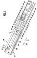
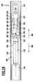
- a pullout guide shown in FIGS. 1 to 9 and designated as a whole by 100 comprises a first guide rail 102 and a second guide rail 104 which are relatively movable by means of a rolling element arrangement (not shown) along an extension direction 106 and an insertion direction 108 directed opposite to the extension direction 106 to the first guide rail 102 is slidably held on the first guide rail 102.
- the first guide rail 102 can be arranged for example on a body of a piece of furniture and the second guide rail 104, for example on an extract of the furniture.
- first guide rail 102 could be arranged on the extract and the second guide rail 104 on the body of the furniture.
- the pullout guide 100 could also comprise further guide rails, which are held displaceably on the first guide rail 102 or on the second guide rail 104 or else between the first guide rail 102 and the second guide rail 104.
- a base 110 in the form of a profiled strip with a U-shaped cross section is arranged on the first guide rail 102.
- a first leg 112 of the base 110 bearing against the first guide rail 102 is held on the first guide rail 102 by means of a plurality of fastening screws 114.
- One of the first guide rail 102 facing away from second leg 116 carries a designated as a whole with 118 retaining means which is releasably secured by means of a plurality of fastening screws 120 to the base 110.
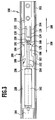
- the retaining device 118 comprises a substantially cuboidal base 122, which is provided with stepped passage openings 124 for the fastening screws 120 and extends along the extension direction 106.
- retaining elements 126 along the extension direction 106 from the front, each comprising a parallel to the extension direction 106 extending claw arm 128 and a retaining claw 130, wherein the retaining claw 130 from the front end of the respective claw arm 128 from inside, d. H. to the longitudinal center plane of the retainer 118, and to the rear, d. H. to the base 122 of the retainer 118.
- the free ends of the retaining claws 130 are spaced from each other.
- a stop projection 132 is formed on the retaining device 118, which protrudes from the front end side of the base 122 along the extension direction 106 and whose front end face forms a stop surface 134.
- the claw arms 128 of the retention members 126 have a formulaic elasticity that allows the leading end portions of the retention members 126 to move apart as the passageway extends between the retention claws 130.
- the retainer 118 comprising the base 122, the stopper projection 132 and the retention members 126 is integrally formed from a suitable resilient plastic material, while the base 110 and the guide rails 102, 104 are preferably formed of a metallic material.
- the retaining device 118 may be formed in particular as an injection molded part.
- the retaining device 118 cooperates in a manner to be described in more detail later with a blocking device designated as a whole with 136, which comprises a substantially rectangular retaining frame 138 which is latched on its underside by means of snap-in feet 140 with passage openings in the second guide rail 104.
- the interior of the holding frame 138 forms a receptacle for a substantially hollow cylindrical damper housing 142.
- the damper housing 142 surrounds an, for example, substantially cylindrical inner space 144, in which a movement damping fluid, such as an oil, is arranged.
- a movement damping fluid such as an oil
- a piston 146 is immersed, which comprises a piston head 148 arranged inside the inner space 144 and a piston rod 152 guided fluid-tightly from the inner space 144 through a rear wall 150 of the damper housing 142.
- the cross section of the piston head 148 substantially corresponds to the cross section of the interior 144.
- the piston head 148 is provided with flow channels 153, through which the movement damping fluid from the area lying before the piston head 148 portion 144 a of the interior 144 in the lying behind the piston head 148 portion 144 b of the interior 144 and in the reverse direction through the piston head 148 can flow through, and while overcoming a considerable flow resistance and overcoming the friction between the piston head jacket and the inner wall of the damper housing 142nd
- the piston 146 is slidably guided on the damper housing 142 as a whole in its longitudinal direction 154 relative to the damper housing 142.
- the piston rod 152 passes through a locking receptacle 156 in a rear end wall 158 of the holding frame 138, in which the piston rod 152 is received so that it is displaceable in its axial direction relative to the holding frame 138, but secured against moving up out of the locking receptacle 156 out ,
- the damper housing 142 is further provided at its front end with a substantially cylindrical projection 160 which is received in a locking receptacle 162 of a front end wall 164 of the support frame 138 that it is secured against moving up out of the locking receptacle 162 out.
- the front end face and the rear end face of the damper housing 142 are thus located on the front end wall 164 and on the rear end wall 158, respectively of the support frame 138 that the damper housing 142 is secured against movement in its axial direction relative to the support frame 138 and thus relative to the locking device 136.
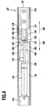
- the piston rod 152 ends at a piston rod head 166, which is separated by a portion 168 of smaller diameter from the piston head side part of the piston rod 152. In the region of the section 168, the piston rod 152 is thus provided with a constriction 170.
- the piston rod head 166 comprises a frustoconical front portion 172 adjoining the portion 168 of the piston rod 152, a cylindrical middle portion 174 adjoining the front portion 172 and a frusto-conical rear portion 176 adjoining the middle portion 174, on which the piston rod 152 ends.
- the surface of the rear portion 176 forms a truncated cone-shaped starting slope 178, with the piston rod head 166 against the retaining elements 126 of the retainer 118 starts when the piston rod 152 moves in the direction of insertion 108 against the retainer 118.
- the truncated cone-shaped surface of the front portion 172 of the piston rod head 166 forms a blocking surface 180, with which the piston rod head 166 rests against the retaining claws 130 of the retaining device 118 in a stop position to be described later.
- the blocking surface 180 is inclined more strongly against the longitudinal direction 154 of the piston 146 than the starting slope 178.
- each of the locking elements 182 is provided at its rear end with a run-on slope 184.
- each of the locking elements 182 each have a cross-sectionally substantially rectangular recess 188.
- the locking device 136 comprising the holding frame 138 and the blocking elements 182 is preferably produced in one piece from a suitable material, preferably from a plastic material.
- the plastic material is chosen so that the locking elements 182 are not or only to a small extent elastically deformable.
- the locking device 136 may be made in particular as an injection molded part made of a plastic material.
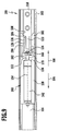
- the retaining claws 130 again move inwardly along the locking surface 180 of the piston rod head 166 along the insertion direction 108 along the insertion direction 108 until the retaining claws 130 engage the constriction 170 of the piston rod 152 and the Retaining elements 126 are again in the retaining position (see Fig. 5).
- the front end face of the piston rod head 166 abuts on the abutment surface 134 of the stopper projection 132, so that the movement of the piston rod 152 is stopped along the insertion direction 108 in a stop position.
- the piston head 148 moves in the interior 144 of the damper housing 142 to the front.
- the volume of the movement damping fluid displaced from the region 144a of the interior during this relative movement between the piston 146 and the damper housing 142 flows through the flow channels 153 in the piston head 148 into the region 144b of the interior. Due to the flow resistance to be overcome in the narrow flow channels 153 and the friction between the piston head 148 and the inner wall of the damper housing 142, a braking force is caused which slows down the movement of the damper housing 142 and thus the movement of the second guide rail 104 along the insertion direction 108.
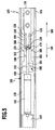
- the piston rod head 166 initially can not move between the retaining claws 130 along the extension direction 106 when the second guide rail 104 with the damper housing 142 is pulled out relative to the first guide rail 102 again along the extension direction 106. Rather, the piston rod head 166 bears with its locking surface 180 at the free ends of the retaining claws 130 and is thus by the retaining elements 126 in the stop position retained as the damper housing 142 moves away in the extension direction 106 of the piston rod head 166.
- the piston rod 152 is again pulled out of the damper housing 142 until the locking elements 182 moving with the damper housing 142 in the extension direction 106 disengage from the retaining elements 126, so that the retaining elements 126 can move back into the release position by spreading the claw arms 128 apart.
- the piston rod head 166 can pass through the passage between the retaining claws 130 and is moved along with the damper housing 142 on further extension of the second guide rail 104 in the extension direction 106.
- this distance can be varied in that the blocking elements 182 are not integrally formed with the holding frame 138 of the locking device 136, but can be fixed releasably to the holding frame 138 in various positions spaced from each other in the longitudinal direction 154.
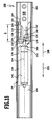
- the piston rod 152 is in its maximum position pushed into the damper housing 142 without the piston rod head 166 having already reached the stop position behind the retaining claws 130, as shown in FIG is. Even in such an exceptional situation, the piston rod head 166 on further insertion of the second guide rail 104 and the damper housing 142 in the direction of insertion 108 may be moved past the retaining claws 130 in the stop position, so that the piston rod 152 again properly pulled out of the damper housing 142 during the next extraction process can be.
- the recesses 188 are provided on the locking elements 182. Namely, as can be seen from Fig. 9, namely, the retaining elements 126 can escape into these recesses 188, when the piston rod head 166 at maximum pushed into the damper housing 142 piston rod 152 reaches the retention claws 130, so that the piston rod head 166 displacing the retaining claws 130 laterally and between them can reach into the stop position (see Fig. 9).
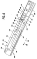
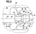
- a second embodiment of the drawer guide 100 shown in FIGS. 10 to 12 and 21 differs from the first embodiment shown in FIGS. 1 to 9 only in that the locking elements 182 of the locking device 136 are not provided with the recesses 188, but themselves in substantially the same width from the rear end wall 158 of the holding frame 138 extend to the rear edge of the abutment surface 186.
- the emergency function discussed above with respect to the first embodiment is ensured in this embodiment by elastically deforming the retention claws 130 of the retention members 126 in the retention position retaining members 126 such that the piston rod head 166 can push apart the free ends of the retaining claws 130 and pass through the passage between the retaining claws 130 in the stop position between the retaining claws 130 and the stopper projection 132.
- the connecting portion of the retaining claws 130 is elastically deformable such that each of the retaining claws 130 is pivotable about the connecting region transversely to its respective longitudinal direction 198 (see FIG to let the piston rod head 166 pass between the free ends of the retaining claws 130.
- the mobility of the retaining claws 130 relative to the respective associated claw arm 128 can also be achieved by connecting each retaining claw 130 via a joint to the respective associated claw arm 128.
- the retention elements 126 are preferably configured such that the longitudinal direction 198 of each retention claw 130 is at the local surface normal 200 of the locking surface 180 of the piston rod head 166 at the location where the locking surface 180 at the free end of the retaining claw 130 is present, an acute angle of at most about 45 °, preferably at most about 20 °, in particular of substantially 0 ° (as shown in Fig. 21) includes.
- FIGS. 10 to 12 the second embodiment shown in FIGS. 10 to 12 is identical in structure and function to the first embodiment, to the above description of which reference is made.
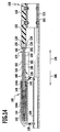
- a third embodiment shown in FIGS. 13 to 20 of an extension guide 100 with a movement damping device 190 differs from the first embodiment shown in FIGS. 1 to 9 in that the retaining elements 126 of the retaining device 118 are in their rest position, in which there is no external force acting on the retaining elements 126, not, as in the first embodiment, in the retaining position, but rather in the release position.
- the piston rod head 166 when passing the retaining claws 130 do not have the same first push back the remindhatteemente 126 in the retaining position in which the retaining claws 130 engage the constriction 170 in front of the piston rod head 166 when the front ends of the retaining elements 126 are reached by the locking elements 182.
- the recesses 188 on the locking elements 182, in which the retaining elements 126 can escape in this embodiment, not as in the first embodiment with a along the extension direction 106 constant cross-section provided, but rather widen these recesses 188 from its rear end to to the rear end wall 158 of the holding frame 138, so that these recesses 188 have a substantially triangular cross-section in the side view of the locking device 136 shown in FIG.
- the locking elements 182 are provided on their sides facing away from the piston rod 152 outer sides, each with a recess 196 which extends from the rear end of the respective locking element 182 almost to the rear end wall 158 of the support frame 138.
- this third embodiment is consistent in construction with the first embodiment described above.
- the claw arms 128 of the retaining elements 126 are not aligned parallel to each other in the rest position but enclose a small acute angle and are thus slightly spread apart, the mutually facing ends of the retaining claws 130 at a distance from each other, which at least the diameter of the central portion 174 of the piston rod head 166, so that the piston rod head 166 does not have to move the retaining claws 130 apart to reach the stop position behind the retaining claws 130.
- the retaining elements 126 are prevented from returning to the release position.
- the retention claws 130 engage the neck 170 in front of the piston rod head 166 (see FIG. 17).
- the claw arms 128 can not bend apart, and thus a return of the retaining elements 126 to the release position by the blocking elements 182 is prevented.
- the piston rod head 166 is initially retained in the stop position behind the retaining claws 130, when the second guide rail 104 with the damper housing 142 relative to the first guide rail 102 is pulled out again along the extension direction 106.
- the damping travel of the movement damping device 190 ie the maximum extension travel, by which the piston rod 152 is pulled out of the damper housing 142 when the second guide rail 104 is pulled out, is thus also determined in this embodiment by the distance s around which the rear edge of the contact surface 186 of FIG locking elements 182 in the end position shown in Fig. 18 behind the front end of the retaining elements 126 is located.
- the recesses 188 are provided on the locking elements 182, in which the retaining elements 126 can escape into it, when the piston rod head 166 reached at maximum in the damper housing 142 inserted piston rod 152, the retaining claws 130, so that the piston rod head 166 the Retaining claws 130 displace laterally under elastic deformation of the claw arms 128 and can pass between the retaining ridges 130 in the stop position (see Fig. 20).
- FIGS. 13 to 20 is identical to the embodiment shown in FIGS. 1 to 9, to the extent of which the above description is made.
Priority Applications (1)
| Application Number | Priority Date | Filing Date | Title |
|---|---|---|---|
| PL05016336T PL1625810T3 (pl) | 2004-08-10 | 2005-07-27 | Urządzenie amortyzujące ruch |
Applications Claiming Priority (1)
| Application Number | Priority Date | Filing Date | Title |
|---|---|---|---|
| DE102004038708A DE102004038708A1 (de) | 2004-08-10 | 2004-08-10 | Bewegungsdämpfungsvorrichtung |
Publications (2)
| Publication Number | Publication Date |
|---|---|
| EP1625810A1 true EP1625810A1 (fr) | 2006-02-15 |
| EP1625810B1 EP1625810B1 (fr) | 2012-01-18 |
Family
ID=35285608
Family Applications (1)
| Application Number | Title | Priority Date | Filing Date |
|---|---|---|---|
| EP05016336A Active EP1625810B1 (fr) | 2004-08-10 | 2005-07-27 | Dispositif amortisseur de mouvement |
Country Status (4)
| Country | Link |
|---|---|
| EP (1) | EP1625810B1 (fr) |
| AT (1) | ATE541479T1 (fr) |
| DE (1) | DE102004038708A1 (fr) |
| PL (1) | PL1625810T3 (fr) |
Cited By (10)
| Publication number | Priority date | Publication date | Assignee | Title |
|---|---|---|---|---|
| EP1817983A1 (fr) * | 2006-02-13 | 2007-08-15 | Grass GmbH | Dispositif pour influencer le mouvement des parties de meuble l'une par rapport à l'autre et une glissière pour tiroirs, ainsi qu'un procédé de fabrication d'un tel dispositif |
| EP1961332A1 (fr) | 2007-02-23 | 2008-08-27 | Weber & Co. GmbH KG | Dispositif d'amortissement pour éléments de meuble mobiles |
| ITRM20100057A1 (it) * | 2010-02-15 | 2011-08-16 | Door & Window Hardware Co | Dispositivo di chiusura morbida per porta scorrevole. |
| EP2457465A1 (fr) * | 2010-11-29 | 2012-05-30 | Grass GmbH | Dispositif de verrouillage |
| WO2013079557A1 (fr) * | 2011-11-28 | 2013-06-06 | Paul Hettich Gmbh & Co. Kg | Dispositif de guidage télescopique |
| EP3138441A1 (fr) * | 2015-09-04 | 2017-03-08 | Grass GmbH | Dispositif d'amortissement destine a amortir le mouvement d'ouverture d'un element de meuble mobile |
| EP1817984B1 (fr) * | 2006-02-13 | 2017-04-05 | Grass GmbH | Dispositif pour influencer le mouvement des parties de meuble l'une par rapport à l'autre, en particulier pour des glissières pour tiroirs ainsi qu'une glissière pour tiroirs avec un tel dispositif |
| AT518398B1 (de) * | 2016-04-05 | 2017-10-15 | Blum Gmbh Julius | Möbelantrieb |
| CN107989502A (zh) * | 2017-12-22 | 2018-05-04 | 广东东泰五金精密制造有限公司 | 一种家具阻尼弹力的调节机构 |
| CN113983110A (zh) * | 2021-10-08 | 2022-01-28 | 山东大学 | 一种面向于冲击地压的机液联合缓冲器 |
Families Citing this family (5)
| Publication number | Priority date | Publication date | Assignee | Title |
|---|---|---|---|---|
| DE202005006724U1 (de) * | 2005-02-14 | 2005-07-28 | Grass Gmbh | Schubladenführung |
| DE202006006179U1 (de) * | 2006-04-18 | 2007-08-30 | Paul Hettich Gmbh & Co. Kg | Vorrichtung zur Erleichterung des Herausziehens eines Auszugteiles aus einem Möbelkorpus |
| DE102008010771B4 (de) | 2008-02-25 | 2018-03-01 | Kesseböhmer Holding Kg | Möbel |
| DE102008010768A1 (de) * | 2008-02-25 | 2009-08-27 | Heinrich J. Kesseböhmer KG | Möbel |
| DE102009020994B4 (de) * | 2009-05-12 | 2017-08-10 | Karl Simon Gmbh & Co. Kg | Einzugvorrichtung |
Citations (4)
| Publication number | Priority date | Publication date | Assignee | Title |
|---|---|---|---|---|
| EP0386731B1 (fr) | 1989-03-08 | 1992-12-30 | Schock Metallwerk GmbH | Dispositif escamotable |
| DE19935120A1 (de) * | 1999-07-27 | 2001-02-15 | Bulthaup Gmbh & Co | Vorrichtung zum Öffnen und Schließen einer Schublade |
| US20030234604A1 (en) * | 2002-06-20 | 2003-12-25 | Nan Juen International Co., Ltd. | Buffer and return device for a slide rail in a drawer |
| DE10256133A1 (de) | 2002-11-29 | 2004-06-17 | Grass Gmbh | Kupplungsvorrichtung für ein in einer Ausziehführungsgarnitur integriertes Dämpfelement |
Family Cites Families (5)
| Publication number | Priority date | Publication date | Assignee | Title |
|---|---|---|---|---|
| DE19717937A1 (de) * | 1996-11-08 | 1998-05-20 | Grass Ag | Brems- und Dämpfungselement für bewegliche Möbelteile |
| DE10008350C2 (de) * | 2000-02-23 | 2003-01-30 | Bulthaup Gmbh & Co | Vorrichtung zum Öffnen einer Möbelabdeckung, wie z. B. einer Schublade, Tür oder Klappe |
| DE20107426U1 (de) * | 2001-04-30 | 2001-08-30 | Zimmer Guenther Stephan | Bremsregler mit Luft- oder Flüssigkeitsdämpfung, insbesondere zur Endlagendämpfung von Schubladen, Türen o.dgl. Einrichtungen |
| DE10147786C1 (de) * | 2001-09-27 | 2003-02-13 | Itw Automotive Prod Gmbh & Co | Vorrichtung zum gedämpften Einzug von beweglichen Bauteilen in eine Endlage |
| DE20218067U1 (de) * | 2002-11-19 | 2003-01-30 | Blum Gmbh Julius | Schließ- und/oder Einzugsvorrichtung für bewegbare Möbelteile |
-
2004
- 2004-08-10 DE DE102004038708A patent/DE102004038708A1/de not_active Withdrawn
-
2005
- 2005-07-27 AT AT05016336T patent/ATE541479T1/de active
- 2005-07-27 PL PL05016336T patent/PL1625810T3/pl unknown
- 2005-07-27 EP EP05016336A patent/EP1625810B1/fr active Active
Patent Citations (4)
| Publication number | Priority date | Publication date | Assignee | Title |
|---|---|---|---|---|
| EP0386731B1 (fr) | 1989-03-08 | 1992-12-30 | Schock Metallwerk GmbH | Dispositif escamotable |
| DE19935120A1 (de) * | 1999-07-27 | 2001-02-15 | Bulthaup Gmbh & Co | Vorrichtung zum Öffnen und Schließen einer Schublade |
| US20030234604A1 (en) * | 2002-06-20 | 2003-12-25 | Nan Juen International Co., Ltd. | Buffer and return device for a slide rail in a drawer |
| DE10256133A1 (de) | 2002-11-29 | 2004-06-17 | Grass Gmbh | Kupplungsvorrichtung für ein in einer Ausziehführungsgarnitur integriertes Dämpfelement |
Cited By (18)
| Publication number | Priority date | Publication date | Assignee | Title |
|---|---|---|---|---|
| EP1817984B1 (fr) * | 2006-02-13 | 2017-04-05 | Grass GmbH | Dispositif pour influencer le mouvement des parties de meuble l'une par rapport à l'autre, en particulier pour des glissières pour tiroirs ainsi qu'une glissière pour tiroirs avec un tel dispositif |
| EP1817983A1 (fr) * | 2006-02-13 | 2007-08-15 | Grass GmbH | Dispositif pour influencer le mouvement des parties de meuble l'une par rapport à l'autre et une glissière pour tiroirs, ainsi qu'un procédé de fabrication d'un tel dispositif |
| US8011743B2 (en) | 2006-02-13 | 2011-09-06 | Grass Gmbh | Device for influencing the movement of furniture parts which can be moved relative to one another, and drawer guide, and method of producing the device |
| DE102007009076A1 (de) | 2007-02-23 | 2008-08-28 | Weber & Co. Gmbh Kg | Dämpfungseinrichtung für bewegbare Möbelteile |
| EP1961332A1 (fr) | 2007-02-23 | 2008-08-27 | Weber & Co. GmbH KG | Dispositif d'amortissement pour éléments de meuble mobiles |
| ITRM20100057A1 (it) * | 2010-02-15 | 2011-08-16 | Door & Window Hardware Co | Dispositivo di chiusura morbida per porta scorrevole. |
| EP2457465A1 (fr) * | 2010-11-29 | 2012-05-30 | Grass GmbH | Dispositif de verrouillage |
| WO2013079557A1 (fr) * | 2011-11-28 | 2013-06-06 | Paul Hettich Gmbh & Co. Kg | Dispositif de guidage télescopique |
| EP3138441A1 (fr) * | 2015-09-04 | 2017-03-08 | Grass GmbH | Dispositif d'amortissement destine a amortir le mouvement d'ouverture d'un element de meuble mobile |
| US9885205B2 (en) | 2015-09-04 | 2018-02-06 | Grass Gmbh | Damping device for the damping of the opening movement of a moveable furniture part |
| CN106617811B (zh) * | 2015-09-04 | 2019-02-12 | 格耐使有限责任公司 | 用于缓冲可动的家具部件的打开运动的缓冲装置 |
| CN106617811A (zh) * | 2015-09-04 | 2017-05-10 | 格耐使有限责任公司 | 用于缓冲可动的家具部件的打开运动的缓冲装置 |
| AT518398B1 (de) * | 2016-04-05 | 2017-10-15 | Blum Gmbh Julius | Möbelantrieb |
| AT518398A4 (de) * | 2016-04-05 | 2017-10-15 | Blum Gmbh Julius | Möbelantrieb |
| US10653240B2 (en) | 2016-04-05 | 2020-05-19 | Julius Blum Gmbh | Furniture drive |
| CN107989502A (zh) * | 2017-12-22 | 2018-05-04 | 广东东泰五金精密制造有限公司 | 一种家具阻尼弹力的调节机构 |
| CN113983110B (zh) * | 2021-10-08 | 2022-06-17 | 山东大学 | 一种面向于冲击地压的机液联合缓冲器 |
| CN113983110A (zh) * | 2021-10-08 | 2022-01-28 | 山东大学 | 一种面向于冲击地压的机液联合缓冲器 |
Also Published As
| Publication number | Publication date |
|---|---|
| ATE541479T1 (de) | 2012-02-15 |
| PL1625810T3 (pl) | 2012-06-29 |
| EP1625810B1 (fr) | 2012-01-18 |
| DE102004038708A1 (de) | 2006-03-09 |
Similar Documents
| Publication | Publication Date | Title |
|---|---|---|
| EP1625810B1 (fr) | Dispositif amortisseur de mouvement | |
| EP1561398B1 (fr) | Monture de guidage à coulisse pour tiroirs | |
| DE10256133B4 (de) | Ausziehführungsgarnitur mit Schienensystem | |
| DE19835466B4 (de) | Bremsvorrichtung mit Schließfolgeregler für bewegliche Möbelteile | |
| DE102017107461A1 (de) | Bewegungsanordnung | |
| EP2445376B1 (fr) | Dispositif de retour automatique et guidage télescopique | |
| EP3429430B1 (fr) | Dispositif de fermeture automatique et glissière de tiroir | |
| EP0386731B1 (fr) | Dispositif escamotable | |
| DE102012110648A1 (de) | Verriegelungselement, Verbindungsanordnung, Anordnung aus einem ersten Bauteil und einem zweiten Bauteil und Verfahren zur Montage einer solchen Anordnung | |
| DE102017113063A1 (de) | Tragschienenbefestigung | |
| DE102004059802A1 (de) | Schubkastenführungsschiene | |
| DE102013005830A1 (de) | Gleitschiene zum Spannen und Führen eines Endlostriebmittels und Verfahren zum Herstellen der Gleitschiene | |
| AT518398B1 (de) | Möbelantrieb | |
| DE102007041613A1 (de) | Koppelungseinrichtung für ein Übertragungsmittel, insbesondere eines Fahrzeugsitzes mit crashaktiver Kopfstütze, Fahrzeugsitz und Verfahren | |
| DE102014112258A1 (de) | Clipsystem | |
| AT514666A2 (de) | Führungsvorrichtung für bewegbare Möbelteile | |
| DE102009020994B4 (de) | Einzugvorrichtung | |
| DE102013217712B4 (de) | Auszugführung | |
| EP2174570A1 (fr) | Guidage d'extraction de rouleaux | |
| DE20319598U1 (de) | Einzugsautomatik für Schubladen-Ausziehführungen | |
| EP3062661B1 (fr) | Dispositif pour ouvrir une partie de meuble mobile | |
| DE102012017685B4 (de) | Kompensationsvorrichtung für einen Bowdenzug | |
| DE202018105183U1 (de) | Kollisionsdämpfer für Möbelteile | |
| DE102021108249A1 (de) | Koppelelement, Schließsystem und Möbel | |
| DE202020106340U1 (de) | Vorrichtung zur Führung eines Möbelauszugs, Möbelauszug und Möbel |
Legal Events
| Date | Code | Title | Description |
|---|---|---|---|
| PUAI | Public reference made under article 153(3) epc to a published international application that has entered the european phase |
Free format text: ORIGINAL CODE: 0009012 |
|
| AK | Designated contracting states |
Kind code of ref document: A1 Designated state(s): AT BE BG CH CY CZ DE DK EE ES FI FR GB GR HU IE IS IT LI LT LU LV MC NL PL PT RO SE SI SK TR |
|
| AX | Request for extension of the european patent |
Extension state: AL BA HR MK YU |
|
| 17P | Request for examination filed |
Effective date: 20060728 |
|
| 17Q | First examination report despatched |
Effective date: 20060824 |
|
| AKX | Designation fees paid |
Designated state(s): AT BE BG CH CY CZ DE DK EE ES FI FR GB GR HU IE IS IT LI LT LU LV MC NL PL PT RO SE SI SK TR |
|
| GRAP | Despatch of communication of intention to grant a patent |
Free format text: ORIGINAL CODE: EPIDOSNIGR1 |
|
| GRAS | Grant fee paid |
Free format text: ORIGINAL CODE: EPIDOSNIGR3 |
|
| GRAA | (expected) grant |
Free format text: ORIGINAL CODE: 0009210 |
|
| AK | Designated contracting states |
Kind code of ref document: B1 Designated state(s): AT BE BG CH CY CZ DE DK EE ES FI FR GB GR HU IE IS IT LI LT LU LV MC NL PL PT RO SE SI SK TR |
|
| REG | Reference to a national code |
Ref country code: GB Ref legal event code: FG4D Free format text: NOT ENGLISH |
|
| REG | Reference to a national code |
Ref country code: CH Ref legal event code: EP |
|
| REG | Reference to a national code |
Ref country code: AT Ref legal event code: REF Ref document number: 541479 Country of ref document: AT Kind code of ref document: T Effective date: 20120215 Ref country code: IE Ref legal event code: FG4D Free format text: LANGUAGE OF EP DOCUMENT: GERMAN |
|
| REG | Reference to a national code |
Ref country code: DE Ref legal event code: R096 Ref document number: 502005012354 Country of ref document: DE Effective date: 20120322 |
|
| REG | Reference to a national code |
Ref country code: NL Ref legal event code: VDEP Effective date: 20120118 |
|
| LTIE | Lt: invalidation of european patent or patent extension |
Effective date: 20120118 |
|
| REG | Reference to a national code |
Ref country code: PL Ref legal event code: T3 |
|
| PG25 | Lapsed in a contracting state [announced via postgrant information from national office to epo] |
Ref country code: LT Free format text: LAPSE BECAUSE OF FAILURE TO SUBMIT A TRANSLATION OF THE DESCRIPTION OR TO PAY THE FEE WITHIN THE PRESCRIBED TIME-LIMIT Effective date: 20120118 Ref country code: IS Free format text: LAPSE BECAUSE OF FAILURE TO SUBMIT A TRANSLATION OF THE DESCRIPTION OR TO PAY THE FEE WITHIN THE PRESCRIBED TIME-LIMIT Effective date: 20120518 Ref country code: BG Free format text: LAPSE BECAUSE OF FAILURE TO SUBMIT A TRANSLATION OF THE DESCRIPTION OR TO PAY THE FEE WITHIN THE PRESCRIBED TIME-LIMIT Effective date: 20120418 Ref country code: NL Free format text: LAPSE BECAUSE OF FAILURE TO SUBMIT A TRANSLATION OF THE DESCRIPTION OR TO PAY THE FEE WITHIN THE PRESCRIBED TIME-LIMIT Effective date: 20120118 |
|
| REG | Reference to a national code |
Ref country code: IE Ref legal event code: FD4D |
|
| PG25 | Lapsed in a contracting state [announced via postgrant information from national office to epo] |
Ref country code: PT Free format text: LAPSE BECAUSE OF FAILURE TO SUBMIT A TRANSLATION OF THE DESCRIPTION OR TO PAY THE FEE WITHIN THE PRESCRIBED TIME-LIMIT Effective date: 20120518 Ref country code: GR Free format text: LAPSE BECAUSE OF FAILURE TO SUBMIT A TRANSLATION OF THE DESCRIPTION OR TO PAY THE FEE WITHIN THE PRESCRIBED TIME-LIMIT Effective date: 20120419 Ref country code: LV Free format text: LAPSE BECAUSE OF FAILURE TO SUBMIT A TRANSLATION OF THE DESCRIPTION OR TO PAY THE FEE WITHIN THE PRESCRIBED TIME-LIMIT Effective date: 20120118 Ref country code: FI Free format text: LAPSE BECAUSE OF FAILURE TO SUBMIT A TRANSLATION OF THE DESCRIPTION OR TO PAY THE FEE WITHIN THE PRESCRIBED TIME-LIMIT Effective date: 20120118 |
|
| PG25 | Lapsed in a contracting state [announced via postgrant information from national office to epo] |
Ref country code: CY Free format text: LAPSE BECAUSE OF FAILURE TO SUBMIT A TRANSLATION OF THE DESCRIPTION OR TO PAY THE FEE WITHIN THE PRESCRIBED TIME-LIMIT Effective date: 20120118 |
|
| PG25 | Lapsed in a contracting state [announced via postgrant information from national office to epo] |
Ref country code: DK Free format text: LAPSE BECAUSE OF FAILURE TO SUBMIT A TRANSLATION OF THE DESCRIPTION OR TO PAY THE FEE WITHIN THE PRESCRIBED TIME-LIMIT Effective date: 20120118 Ref country code: CZ Free format text: LAPSE BECAUSE OF FAILURE TO SUBMIT A TRANSLATION OF THE DESCRIPTION OR TO PAY THE FEE WITHIN THE PRESCRIBED TIME-LIMIT Effective date: 20120118 Ref country code: RO Free format text: LAPSE BECAUSE OF FAILURE TO SUBMIT A TRANSLATION OF THE DESCRIPTION OR TO PAY THE FEE WITHIN THE PRESCRIBED TIME-LIMIT Effective date: 20120118 Ref country code: SI Free format text: LAPSE BECAUSE OF FAILURE TO SUBMIT A TRANSLATION OF THE DESCRIPTION OR TO PAY THE FEE WITHIN THE PRESCRIBED TIME-LIMIT Effective date: 20120118 Ref country code: SE Free format text: LAPSE BECAUSE OF FAILURE TO SUBMIT A TRANSLATION OF THE DESCRIPTION OR TO PAY THE FEE WITHIN THE PRESCRIBED TIME-LIMIT Effective date: 20120118 Ref country code: EE Free format text: LAPSE BECAUSE OF FAILURE TO SUBMIT A TRANSLATION OF THE DESCRIPTION OR TO PAY THE FEE WITHIN THE PRESCRIBED TIME-LIMIT Effective date: 20120118 Ref country code: IE Free format text: LAPSE BECAUSE OF FAILURE TO SUBMIT A TRANSLATION OF THE DESCRIPTION OR TO PAY THE FEE WITHIN THE PRESCRIBED TIME-LIMIT Effective date: 20120118 |
|
| PLBE | No opposition filed within time limit |
Free format text: ORIGINAL CODE: 0009261 |
|
| STAA | Information on the status of an ep patent application or granted ep patent |
Free format text: STATUS: NO OPPOSITION FILED WITHIN TIME LIMIT |
|
| PG25 | Lapsed in a contracting state [announced via postgrant information from national office to epo] |
Ref country code: SK Free format text: LAPSE BECAUSE OF FAILURE TO SUBMIT A TRANSLATION OF THE DESCRIPTION OR TO PAY THE FEE WITHIN THE PRESCRIBED TIME-LIMIT Effective date: 20120118 |
|
| 26N | No opposition filed |
Effective date: 20121019 |
|
| BERE | Be: lapsed |
Owner name: SCHOCK METALLWERK G.M.B.H. Effective date: 20120731 |
|
| REG | Reference to a national code |
Ref country code: DE Ref legal event code: R097 Ref document number: 502005012354 Country of ref document: DE Effective date: 20121019 |
|
| PG25 | Lapsed in a contracting state [announced via postgrant information from national office to epo] |
Ref country code: MC Free format text: LAPSE BECAUSE OF NON-PAYMENT OF DUE FEES Effective date: 20120731 |
|
| REG | Reference to a national code |
Ref country code: CH Ref legal event code: PL |
|
| GBPC | Gb: european patent ceased through non-payment of renewal fee |
Effective date: 20120727 |
|
| REG | Reference to a national code |
Ref country code: FR Ref legal event code: ST Effective date: 20130329 |
|
| PG25 | Lapsed in a contracting state [announced via postgrant information from national office to epo] |
Ref country code: LI Free format text: LAPSE BECAUSE OF NON-PAYMENT OF DUE FEES Effective date: 20120731 Ref country code: FR Free format text: LAPSE BECAUSE OF NON-PAYMENT OF DUE FEES Effective date: 20120731 Ref country code: CH Free format text: LAPSE BECAUSE OF NON-PAYMENT OF DUE FEES Effective date: 20120731 Ref country code: GB Free format text: LAPSE BECAUSE OF NON-PAYMENT OF DUE FEES Effective date: 20120727 Ref country code: ES Free format text: LAPSE BECAUSE OF FAILURE TO SUBMIT A TRANSLATION OF THE DESCRIPTION OR TO PAY THE FEE WITHIN THE PRESCRIBED TIME-LIMIT Effective date: 20120429 |
|
| PG25 | Lapsed in a contracting state [announced via postgrant information from national office to epo] |
Ref country code: BE Free format text: LAPSE BECAUSE OF NON-PAYMENT OF DUE FEES Effective date: 20120731 |
|
| REG | Reference to a national code |
Ref country code: AT Ref legal event code: MM01 Ref document number: 541479 Country of ref document: AT Kind code of ref document: T Effective date: 20120731 |
|
| PG25 | Lapsed in a contracting state [announced via postgrant information from national office to epo] |
Ref country code: AT Free format text: LAPSE BECAUSE OF NON-PAYMENT OF DUE FEES Effective date: 20120731 |
|
| PG25 | Lapsed in a contracting state [announced via postgrant information from national office to epo] |
Ref country code: TR Free format text: LAPSE BECAUSE OF FAILURE TO SUBMIT A TRANSLATION OF THE DESCRIPTION OR TO PAY THE FEE WITHIN THE PRESCRIBED TIME-LIMIT Effective date: 20120118 |
|
| PG25 | Lapsed in a contracting state [announced via postgrant information from national office to epo] |
Ref country code: LU Free format text: LAPSE BECAUSE OF NON-PAYMENT OF DUE FEES Effective date: 20120727 |
|
| PG25 | Lapsed in a contracting state [announced via postgrant information from national office to epo] |
Ref country code: HU Free format text: LAPSE BECAUSE OF FAILURE TO SUBMIT A TRANSLATION OF THE DESCRIPTION OR TO PAY THE FEE WITHIN THE PRESCRIBED TIME-LIMIT Effective date: 20050727 |
|
| REG | Reference to a national code |
Ref country code: DE Ref legal event code: R082 Ref document number: 502005012354 Country of ref document: DE Representative=s name: HOEGER, STELLRECHT & PARTNER PATENTANWAELTE MB, DE |
|
| REG | Reference to a national code |
Ref country code: DE Ref legal event code: R079 Ref document number: 502005012354 Country of ref document: DE Free format text: PREVIOUS MAIN CLASS: A47B0088040000 Ipc: A47B0088400000 |
|
| REG | Reference to a national code |
Ref country code: DE Ref legal event code: R082 Ref document number: 502005012354 Country of ref document: DE Representative=s name: DTS PATENT- UND RECHTSANWAELTE SCHNEKENBUEHL U, DE Ref country code: DE Ref legal event code: R082 Ref document number: 502005012354 Country of ref document: DE Representative=s name: HOEGER, STELLRECHT & PARTNER PATENTANWAELTE MB, DE |
|
| REG | Reference to a national code |
Ref country code: DE Ref legal event code: R082 Ref document number: 502005012354 Country of ref document: DE Representative=s name: DTS PATENT- UND RECHTSANWAELTE SCHNEKENBUEHL U, DE |
|
| P01 | Opt-out of the competence of the unified patent court (upc) registered |
Effective date: 20230601 |
|
| PGFP | Annual fee paid to national office [announced via postgrant information from national office to epo] |
Ref country code: IT Payment date: 20230731 Year of fee payment: 19 |
|
| PGFP | Annual fee paid to national office [announced via postgrant information from national office to epo] |
Ref country code: PL Payment date: 20230718 Year of fee payment: 19 Ref country code: DE Payment date: 20230720 Year of fee payment: 19 |