EP1625810A1 - Movement damping device - Google Patents
Movement damping device Download PDFInfo
- Publication number
- EP1625810A1 EP1625810A1 EP05016336A EP05016336A EP1625810A1 EP 1625810 A1 EP1625810 A1 EP 1625810A1 EP 05016336 A EP05016336 A EP 05016336A EP 05016336 A EP05016336 A EP 05016336A EP 1625810 A1 EP1625810 A1 EP 1625810A1
- Authority
- EP
- European Patent Office
- Prior art keywords
- retaining
- piston rod
- damper housing
- damping device
- retaining element
- Prior art date
- Legal status (The legal status is an assumption and is not a legal conclusion. Google has not performed a legal analysis and makes no representation as to the accuracy of the status listed.)
- Granted
Links
- 238000013016 damping Methods 0.000 title claims description 66
- 210000000078 claw Anatomy 0.000 claims description 76
- 238000003780 insertion Methods 0.000 claims description 48
- 230000037431 insertion Effects 0.000 claims description 48
- 230000000903 blocking effect Effects 0.000 claims description 30
- 230000014759 maintenance of location Effects 0.000 claims description 16
- 230000009471 action Effects 0.000 claims description 6
- 230000002996 emotional effect Effects 0.000 claims 1
- 230000000694 effects Effects 0.000 description 6
- 230000008878 coupling Effects 0.000 description 5
- 238000010168 coupling process Methods 0.000 description 5
- 238000005859 coupling reaction Methods 0.000 description 5
- 239000000463 material Substances 0.000 description 5
- 239000000243 solution Substances 0.000 description 5
- 238000000605 extraction Methods 0.000 description 4
- 239000012530 fluid Substances 0.000 description 4
- 230000000717 retained effect Effects 0.000 description 3
- 230000001154 acute effect Effects 0.000 description 2
- 230000008901 benefit Effects 0.000 description 2
- 238000010276 construction Methods 0.000 description 2
- 230000005489 elastic deformation Effects 0.000 description 2
- 238000002347 injection Methods 0.000 description 2
- 239000007924 injection Substances 0.000 description 2
- 238000003754 machining Methods 0.000 description 2
- 230000007246 mechanism Effects 0.000 description 2
- 239000002184 metal Substances 0.000 description 2
- 238000000034 method Methods 0.000 description 2
- 230000008569 process Effects 0.000 description 2
- TVEXGJYMHHTVKP-UHFFFAOYSA-N 6-oxabicyclo[3.2.1]oct-3-en-7-one Chemical compound C1C2C(=O)OC1C=CC2 TVEXGJYMHHTVKP-UHFFFAOYSA-N 0.000 description 1
- 230000002411 adverse Effects 0.000 description 1
- 230000036461 convulsion Effects 0.000 description 1
- 238000006073 displacement reaction Methods 0.000 description 1
- 230000003993 interaction Effects 0.000 description 1
- 238000004519 manufacturing process Methods 0.000 description 1
- 238000013017 mechanical damping Methods 0.000 description 1
- 239000007769 metal material Substances 0.000 description 1
- 238000005096 rolling process Methods 0.000 description 1
- 230000007480 spreading Effects 0.000 description 1
- 238000003892 spreading Methods 0.000 description 1
Images


Classifications
-
- A—HUMAN NECESSITIES
- A47—FURNITURE; DOMESTIC ARTICLES OR APPLIANCES; COFFEE MILLS; SPICE MILLS; SUCTION CLEANERS IN GENERAL
- A47B—TABLES; DESKS; OFFICE FURNITURE; CABINETS; DRAWERS; GENERAL DETAILS OF FURNITURE
- A47B88/00—Drawers for tables, cabinets or like furniture; Guides for drawers
- A47B88/40—Sliding drawers; Slides or guides therefor
- A47B88/453—Actuated drawers
- A47B88/46—Actuated drawers operated by mechanically-stored energy, e.g. by springs
- A47B88/467—Actuated drawers operated by mechanically-stored energy, e.g. by springs self-closing
-
- A—HUMAN NECESSITIES
- A47—FURNITURE; DOMESTIC ARTICLES OR APPLIANCES; COFFEE MILLS; SPICE MILLS; SUCTION CLEANERS IN GENERAL
- A47B—TABLES; DESKS; OFFICE FURNITURE; CABINETS; DRAWERS; GENERAL DETAILS OF FURNITURE
- A47B2210/00—General construction of drawers, guides and guide devices
- A47B2210/0091—Drawer movement damping
- A47B2210/0094—Drawer damping device with 2 relatively movable parts to convert kinetic energy
Definitions
- the present invention relates to a movement damping device comprising a damper housing, a piston displaceable relative to the damper housing with a piston rod and a retaining device, which prevents the piston rod to follow the movement of the damper housing when the damper housing moves away from the retaining device along its extension direction until the piston rod has been pulled out of the damper housing by a predetermined pull-out distance and then releases the piston rod.
- Such movement damping devices are known from the prior art and, in particular in pull-out guides which comprise at least one first guide rail and a second guide rail which can be displaced relative to the first guide rail, can be used to control the speed of the second guide rail relative to the first guide rail in the first guide rail End phase of the movement of the second guide rail in the insertion position to reduce or at least limit, so that a held on the pullout guide extract moves as gently as possible in the insertion position.
- the effect of the movement damping device is based on the piston having to overcome a resistance force, for example a flow resistance or a frictional resistance, in order to move relative to the damper housing, so that the kinetic energy of the guide rail to be braked is dissipated.
- a resistance force for example a flow resistance or a frictional resistance
- Such a retaining means may for example comprise a piston rod end mounted on the magnet, which is retained on a likewise magnetic or magnetizable stop of the piston rod until the piston rod has been completely pulled out of the damper housing, whereupon the magnet at the piston rod end of the stop of the piston rod dissolves and with the damper housing is moved.
- This solution has the disadvantage that additional components are required and the permanent magnet used is relatively expensive.
- both at the beginning of the extension movement of the damper housing and then also when the detachment of the magnet from the stop of the piston rod an unpleasant jerk occurs because the magnetic attraction must be overcome in a very small displacement.
- a Auszieh Installationsgarnitur with a rail system which includes a fixed carcass rail and a directly or indirectly on a center rail thereon longitudinally displaceably mounted drawer rail, wherein both a damping device as a coupling device between the fixed rail and the linearly movable drawer slide are provided, wherein the damping device includes a cylinder and a linearly movable piston rod damped therein, wherein the cylinder is connected to the movable drawer rail and the piston rod with a first part of the coupling device, which with a second part of the coupling device on the carcass rail temporarily positively and repeatedly releasably cooperates, wherein the first part of the coupling device includes a hook body which is arranged on the free end of the piston rod to a mounting portion, and at least one return hook is arranged at the free end of the hook body , which can be moved elastically resiliently by the action of force of a fixedly connected to the drawer rail control wedge, and wherein the second part of
- the present invention has for its object to provide a movement damping device of the type mentioned above, which allows in a simple and reliable manner a return movement of the piston rod into its initial position relative to the damper housing when pulling the damper housing along the extension direction.
- a motion damping device having the features of the preamble of claim 1 according to the invention that the retaining device comprises at least one retaining element which engages in a retaining position an end portion of the piston rod so that the piston rod is prevented from following the movement of the damper housing , and in a release position allows the end portion of the piston rod passes, and that the motion damping device comprises a locking device with at least one blocking element, which prevents the retaining element from the retaining position moves to the release position until the piston rod pulled out of the damper housing by the predetermined Auszugweg has been, and then releases the movement of the retaining element in the release position.
- the solution according to the invention is thus based on the concept of retaining the piston rod in a stop position by means of positive locking with at least one retaining element of the retaining device until the damper housing has been moved by the predetermined extension travel in the extension direction and thus the piston rod has been pulled out of the damper housing by this withdrawal path.
- the retaining element is prevented by a locking element associated with the blocking element, that is not or at least not exclusively by latching with the piston rod, from it, to release the movement of the piston rod in the extension direction.
- the solution according to the invention has the advantage that the piston rod does not have to carry a movable section at its end region and thus, in particular when using a damper with a cylindrical piston rod, preferably made of metal, by simple, in particular machining, machining can be shaped so that it cooperates with the at least one retaining element, without the attachment of additional parts is required.
- the piston rod may be integrally formed.
- the interaction of the blocking element with the retaining element can basically be of any nature.
- the blocking element prevents by positive engagement with the retaining element, the retaining element on the movement of the retaining position in the release position.
- the movement damping device according to the invention can be used both in pull-outs with self-closing device and in pull-outs without self-closing device.
- Such a self-retracting device engages when the extract has reached a Disksstartwolf on the extract or on a guide rail of an extension guide and moves the extract or the guide rail of the drawer guide automatically in the insertion position.
- the motion damping device preferably comprises at least two retaining elements, wherein in a preferred embodiment of the invention, at least two retaining elements of the retaining means are arranged on opposite sides of the piston rod.
- the retaining device has a tubular construction and comprises a plurality of retaining elements, which are arranged in the retaining position along the circumference of the piston rod.
- the retaining element can be moved in a simple and reliable manner by the piston rod from the retaining position to the free-hold position to allow the piston rod to pass in the direction of insertion, it is provided in a preferred embodiment of the invention that the retaining element a the damper housing facing run-on slope, against which the piston rod starts when it moves in the direction of extension opposite direction of insertion.
- the retaining element has a formula elasticity, by which the retaining element in its rest position, ie occupies the retaining position without the action of an external force.
- the retaining element has a formula elasticity, by which the retaining element in its rest position, i. without the action of an external force occupying the release position.
- the piston rod moves the retaining element from the retaining position into the release position when it passes the retaining element.
- the blocking element moves the retaining element from the release position into the retaining position when the blocking element moves in the direction of pull opposite to the direction of insertion.
- the piston rod is in its maximum position pushed into the damper housing, without the end region of the piston rod having already reached the stop position behind the retaining elements.
- the end region of the piston rod in the extension direction opposite insertion direction is movable past the retaining element when the retaining element is in the retaining position.
- This "emergency function" of the movement damping device can be ensured, for example, in that an end region of the retaining element coming into contact with the piston rod is elastically deformable such that the end region of the piston rod can be moved past the retaining element in the insertion direction opposite the extension direction, when the retaining element is in the retention position.
- the blocking element has a recess into which the retaining element can escape when the end region of the piston rod moves past the retaining element in the insertion direction opposite to the extension direction.
- the retaining device further comprises a stop for the piston rod.
- the at least one retaining element and the stop for the piston rod are formed integrally with each other.
- the blocking element may in particular have a contact surface with which the blocking element can be applied to a contact surface of the retaining element in order to hold the retaining element in the retaining position.
- the blocking element may have a run-on slope, with which the blocking element against the retaining element starts when the blocking element moves in the direction of extension opposite direction of insertion and by which the retaining element is moved from the release position to the retaining position.
- the locking device may in particular be rigidly connected to the damper housing, so that the locking device is always moved together with the damper housing in the extension direction or in the insertion direction.
- the locking device may in particular comprise a holder for the damper housing.
- the position of the lock element is adjustable relative to the damper housing.
- the locking device comprises a connecting device for fixing the locking device to a guide rail of an extension guide.
- the retaining device comprises a connecting device for fixing the retaining device to a guide rail of an extension guide.
- These connecting devices may in particular comprise at least one latching element and / or at least one fastening screw.
- the retaining element in the retaining position can easily engage behind an end region of the piston rod, it can be provided that the end region of the piston rod has a constriction in which the retaining element engages in the retaining position.
- the piston rod can displace the retaining element in a simple manner from the retaining position to the release position when the piston rod moves in the direction of insertion, it can be provided that the end region of the piston rod has a run-on slope, with which the piston rod against the retaining element starts when it moves in the pull-out direction opposite to the insertion direction against the retaining element.
- the end portion of the piston rod has a blocking surface, with which the piston rod rests against the retaining element, while the piston rod is prevented from following the movement of the damper housing along the extension direction.
- the retaining element comprises a retaining claw with a longitudinal direction and that the longitudinal direction of the retaining claw with the local surface normal of the locking surface at the point where the locking surface bears against the retaining claw, while the piston rod is prevented to follow the movement of the damper housing along the extension direction, an angle of at most about 45 °, preferably at most about 20 °, in particular of substantially 0 °, includes.
- Claim 26 is directed to a pullout guide comprising at least a first guide rail and a second guide rail, which is displaceable along a pull-out direction relative to the first guide rail, and a movement damping device according to the invention, wherein the retaining means on the first guide rail and the damper housing on the second guide rail is arranged.
- the first guide rail may be a body-side guide rail and the second guide rail may be an extraction-side guide rail of the pull-out guide.
- first guide rail could be arranged on an extension and the second guide rail on a body of a piece of furniture.
- drawer guide could also comprise further guide rails, which are held displaceably on the first guide rail or on the second guide rail or between the first guide rail and the second guide rail.
- the movement damping device according to the invention is to cooperate with a self-closing device, it is preferably provided that such a self-retraction device is arranged on the pullout guide, which, when the second guide rail is moved in its insertion position relative to the first guide rail, on reaching a Doubleeinzugsstartwolf on a guide rail the pull-out guide attacks and moves this guide rail in the insertion position.
- a pullout guide shown in FIGS. 1 to 9 and designated as a whole by 100 comprises a first guide rail 102 and a second guide rail 104 which are relatively movable by means of a rolling element arrangement (not shown) along an extension direction 106 and an insertion direction 108 directed opposite to the extension direction 106 to the first guide rail 102 is slidably held on the first guide rail 102.
- the first guide rail 102 can be arranged for example on a body of a piece of furniture and the second guide rail 104, for example on an extract of the furniture.
- first guide rail 102 could be arranged on the extract and the second guide rail 104 on the body of the furniture.
- the pullout guide 100 could also comprise further guide rails, which are held displaceably on the first guide rail 102 or on the second guide rail 104 or else between the first guide rail 102 and the second guide rail 104.
- a base 110 in the form of a profiled strip with a U-shaped cross section is arranged on the first guide rail 102.
- a first leg 112 of the base 110 bearing against the first guide rail 102 is held on the first guide rail 102 by means of a plurality of fastening screws 114.
- One of the first guide rail 102 facing away from second leg 116 carries a designated as a whole with 118 retaining means which is releasably secured by means of a plurality of fastening screws 120 to the base 110.
- the retaining device 118 comprises a substantially cuboidal base 122, which is provided with stepped passage openings 124 for the fastening screws 120 and extends along the extension direction 106.
- retaining elements 126 along the extension direction 106 from the front, each comprising a parallel to the extension direction 106 extending claw arm 128 and a retaining claw 130, wherein the retaining claw 130 from the front end of the respective claw arm 128 from inside, d. H. to the longitudinal center plane of the retainer 118, and to the rear, d. H. to the base 122 of the retainer 118.
- the free ends of the retaining claws 130 are spaced from each other.
- a stop projection 132 is formed on the retaining device 118, which protrudes from the front end side of the base 122 along the extension direction 106 and whose front end face forms a stop surface 134.
- the claw arms 128 of the retention members 126 have a formulaic elasticity that allows the leading end portions of the retention members 126 to move apart as the passageway extends between the retention claws 130.
- the retainer 118 comprising the base 122, the stopper projection 132 and the retention members 126 is integrally formed from a suitable resilient plastic material, while the base 110 and the guide rails 102, 104 are preferably formed of a metallic material.
- the retaining device 118 may be formed in particular as an injection molded part.
- the retaining device 118 cooperates in a manner to be described in more detail later with a blocking device designated as a whole with 136, which comprises a substantially rectangular retaining frame 138 which is latched on its underside by means of snap-in feet 140 with passage openings in the second guide rail 104.
- the interior of the holding frame 138 forms a receptacle for a substantially hollow cylindrical damper housing 142.
- the damper housing 142 surrounds an, for example, substantially cylindrical inner space 144, in which a movement damping fluid, such as an oil, is arranged.
- a movement damping fluid such as an oil
- a piston 146 is immersed, which comprises a piston head 148 arranged inside the inner space 144 and a piston rod 152 guided fluid-tightly from the inner space 144 through a rear wall 150 of the damper housing 142.
- the cross section of the piston head 148 substantially corresponds to the cross section of the interior 144.
- the piston head 148 is provided with flow channels 153, through which the movement damping fluid from the area lying before the piston head 148 portion 144 a of the interior 144 in the lying behind the piston head 148 portion 144 b of the interior 144 and in the reverse direction through the piston head 148 can flow through, and while overcoming a considerable flow resistance and overcoming the friction between the piston head jacket and the inner wall of the damper housing 142nd
- the piston 146 is slidably guided on the damper housing 142 as a whole in its longitudinal direction 154 relative to the damper housing 142.
- the piston rod 152 passes through a locking receptacle 156 in a rear end wall 158 of the holding frame 138, in which the piston rod 152 is received so that it is displaceable in its axial direction relative to the holding frame 138, but secured against moving up out of the locking receptacle 156 out ,
- the damper housing 142 is further provided at its front end with a substantially cylindrical projection 160 which is received in a locking receptacle 162 of a front end wall 164 of the support frame 138 that it is secured against moving up out of the locking receptacle 162 out.
- the front end face and the rear end face of the damper housing 142 are thus located on the front end wall 164 and on the rear end wall 158, respectively of the support frame 138 that the damper housing 142 is secured against movement in its axial direction relative to the support frame 138 and thus relative to the locking device 136.
- the piston rod 152 ends at a piston rod head 166, which is separated by a portion 168 of smaller diameter from the piston head side part of the piston rod 152. In the region of the section 168, the piston rod 152 is thus provided with a constriction 170.
- the piston rod head 166 comprises a frustoconical front portion 172 adjoining the portion 168 of the piston rod 152, a cylindrical middle portion 174 adjoining the front portion 172 and a frusto-conical rear portion 176 adjoining the middle portion 174, on which the piston rod 152 ends.
- the surface of the rear portion 176 forms a truncated cone-shaped starting slope 178, with the piston rod head 166 against the retaining elements 126 of the retainer 118 starts when the piston rod 152 moves in the direction of insertion 108 against the retainer 118.
- the truncated cone-shaped surface of the front portion 172 of the piston rod head 166 forms a blocking surface 180, with which the piston rod head 166 rests against the retaining claws 130 of the retaining device 118 in a stop position to be described later.
- the blocking surface 180 is inclined more strongly against the longitudinal direction 154 of the piston 146 than the starting slope 178.
- each of the locking elements 182 is provided at its rear end with a run-on slope 184.
- each of the locking elements 182 each have a cross-sectionally substantially rectangular recess 188.
- the locking device 136 comprising the holding frame 138 and the blocking elements 182 is preferably produced in one piece from a suitable material, preferably from a plastic material.
- the plastic material is chosen so that the locking elements 182 are not or only to a small extent elastically deformable.
- the locking device 136 may be made in particular as an injection molded part made of a plastic material.
- the retaining claws 130 again move inwardly along the locking surface 180 of the piston rod head 166 along the insertion direction 108 along the insertion direction 108 until the retaining claws 130 engage the constriction 170 of the piston rod 152 and the Retaining elements 126 are again in the retaining position (see Fig. 5).
- the front end face of the piston rod head 166 abuts on the abutment surface 134 of the stopper projection 132, so that the movement of the piston rod 152 is stopped along the insertion direction 108 in a stop position.
- the piston head 148 moves in the interior 144 of the damper housing 142 to the front.
- the volume of the movement damping fluid displaced from the region 144a of the interior during this relative movement between the piston 146 and the damper housing 142 flows through the flow channels 153 in the piston head 148 into the region 144b of the interior. Due to the flow resistance to be overcome in the narrow flow channels 153 and the friction between the piston head 148 and the inner wall of the damper housing 142, a braking force is caused which slows down the movement of the damper housing 142 and thus the movement of the second guide rail 104 along the insertion direction 108.
- the piston rod head 166 initially can not move between the retaining claws 130 along the extension direction 106 when the second guide rail 104 with the damper housing 142 is pulled out relative to the first guide rail 102 again along the extension direction 106. Rather, the piston rod head 166 bears with its locking surface 180 at the free ends of the retaining claws 130 and is thus by the retaining elements 126 in the stop position retained as the damper housing 142 moves away in the extension direction 106 of the piston rod head 166.
- the piston rod 152 is again pulled out of the damper housing 142 until the locking elements 182 moving with the damper housing 142 in the extension direction 106 disengage from the retaining elements 126, so that the retaining elements 126 can move back into the release position by spreading the claw arms 128 apart.
- the piston rod head 166 can pass through the passage between the retaining claws 130 and is moved along with the damper housing 142 on further extension of the second guide rail 104 in the extension direction 106.
- this distance can be varied in that the blocking elements 182 are not integrally formed with the holding frame 138 of the locking device 136, but can be fixed releasably to the holding frame 138 in various positions spaced from each other in the longitudinal direction 154.
- the piston rod 152 is in its maximum position pushed into the damper housing 142 without the piston rod head 166 having already reached the stop position behind the retaining claws 130, as shown in FIG is. Even in such an exceptional situation, the piston rod head 166 on further insertion of the second guide rail 104 and the damper housing 142 in the direction of insertion 108 may be moved past the retaining claws 130 in the stop position, so that the piston rod 152 again properly pulled out of the damper housing 142 during the next extraction process can be.
- the recesses 188 are provided on the locking elements 182. Namely, as can be seen from Fig. 9, namely, the retaining elements 126 can escape into these recesses 188, when the piston rod head 166 at maximum pushed into the damper housing 142 piston rod 152 reaches the retention claws 130, so that the piston rod head 166 displacing the retaining claws 130 laterally and between them can reach into the stop position (see Fig. 9).
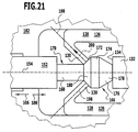
- a second embodiment of the drawer guide 100 shown in FIGS. 10 to 12 and 21 differs from the first embodiment shown in FIGS. 1 to 9 only in that the locking elements 182 of the locking device 136 are not provided with the recesses 188, but themselves in substantially the same width from the rear end wall 158 of the holding frame 138 extend to the rear edge of the abutment surface 186.
- the emergency function discussed above with respect to the first embodiment is ensured in this embodiment by elastically deforming the retention claws 130 of the retention members 126 in the retention position retaining members 126 such that the piston rod head 166 can push apart the free ends of the retaining claws 130 and pass through the passage between the retaining claws 130 in the stop position between the retaining claws 130 and the stopper projection 132.
- the connecting portion of the retaining claws 130 is elastically deformable such that each of the retaining claws 130 is pivotable about the connecting region transversely to its respective longitudinal direction 198 (see FIG to let the piston rod head 166 pass between the free ends of the retaining claws 130.
- the mobility of the retaining claws 130 relative to the respective associated claw arm 128 can also be achieved by connecting each retaining claw 130 via a joint to the respective associated claw arm 128.
- the retention elements 126 are preferably configured such that the longitudinal direction 198 of each retention claw 130 is at the local surface normal 200 of the locking surface 180 of the piston rod head 166 at the location where the locking surface 180 at the free end of the retaining claw 130 is present, an acute angle of at most about 45 °, preferably at most about 20 °, in particular of substantially 0 ° (as shown in Fig. 21) includes.
- FIGS. 10 to 12 the second embodiment shown in FIGS. 10 to 12 is identical in structure and function to the first embodiment, to the above description of which reference is made.
- a third embodiment shown in FIGS. 13 to 20 of an extension guide 100 with a movement damping device 190 differs from the first embodiment shown in FIGS. 1 to 9 in that the retaining elements 126 of the retaining device 118 are in their rest position, in which there is no external force acting on the retaining elements 126, not, as in the first embodiment, in the retaining position, but rather in the release position.
- the piston rod head 166 when passing the retaining claws 130 do not have the same first push back the remindhatteemente 126 in the retaining position in which the retaining claws 130 engage the constriction 170 in front of the piston rod head 166 when the front ends of the retaining elements 126 are reached by the locking elements 182.
- the recesses 188 on the locking elements 182, in which the retaining elements 126 can escape in this embodiment, not as in the first embodiment with a along the extension direction 106 constant cross-section provided, but rather widen these recesses 188 from its rear end to to the rear end wall 158 of the holding frame 138, so that these recesses 188 have a substantially triangular cross-section in the side view of the locking device 136 shown in FIG.
- the locking elements 182 are provided on their sides facing away from the piston rod 152 outer sides, each with a recess 196 which extends from the rear end of the respective locking element 182 almost to the rear end wall 158 of the support frame 138.
- this third embodiment is consistent in construction with the first embodiment described above.
- the claw arms 128 of the retaining elements 126 are not aligned parallel to each other in the rest position but enclose a small acute angle and are thus slightly spread apart, the mutually facing ends of the retaining claws 130 at a distance from each other, which at least the diameter of the central portion 174 of the piston rod head 166, so that the piston rod head 166 does not have to move the retaining claws 130 apart to reach the stop position behind the retaining claws 130.
- the retaining elements 126 are prevented from returning to the release position.
- the retention claws 130 engage the neck 170 in front of the piston rod head 166 (see FIG. 17).
- the claw arms 128 can not bend apart, and thus a return of the retaining elements 126 to the release position by the blocking elements 182 is prevented.
- the piston rod head 166 is initially retained in the stop position behind the retaining claws 130, when the second guide rail 104 with the damper housing 142 relative to the first guide rail 102 is pulled out again along the extension direction 106.
- the damping travel of the movement damping device 190 ie the maximum extension travel, by which the piston rod 152 is pulled out of the damper housing 142 when the second guide rail 104 is pulled out, is thus also determined in this embodiment by the distance s around which the rear edge of the contact surface 186 of FIG locking elements 182 in the end position shown in Fig. 18 behind the front end of the retaining elements 126 is located.
- the recesses 188 are provided on the locking elements 182, in which the retaining elements 126 can escape into it, when the piston rod head 166 reached at maximum in the damper housing 142 inserted piston rod 152, the retaining claws 130, so that the piston rod head 166 the Retaining claws 130 displace laterally under elastic deformation of the claw arms 128 and can pass between the retaining ridges 130 in the stop position (see Fig. 20).
- FIGS. 13 to 20 is identical to the embodiment shown in FIGS. 1 to 9, to the extent of which the above description is made.
Abstract
Description
Die vorliegende Erfindung betrifft eine Bewegungsdämpfungsvorrichtung, die ein Dämpfergehäuse, einen relativ zu dem Dämpfergehäuse verschiebbaren Kolben mit einer Kolbenstange und eine Rückhalteeinrichtung umfasst, welche die Kolbenstange daran hindert, der Bewegung des Dämpfergehäuses zu foigen, wenn sich das Dämpfergehäuses längs seiner Auszugrichtung von der Rückhalteeinrichtung wegbewegt, bis die Kolbenstange um einen vorgegebenen Auszugweg aus dem Dämpfergehäuse herausgezogen worden ist, und dann die Kolbenstange freigibt.The present invention relates to a movement damping device comprising a damper housing, a piston displaceable relative to the damper housing with a piston rod and a retaining device, which prevents the piston rod to follow the movement of the damper housing when the damper housing moves away from the retaining device along its extension direction until the piston rod has been pulled out of the damper housing by a predetermined pull-out distance and then releases the piston rod.
Solche Bewegungsdämpfungsvorrichtungen sind aus dem Stand der Technik bekannt und können insbesondere bei Auszugführungen, die mindestens eine erste Führungsschiene und eine zweite, relativ zu der ersten Führungsschiene verschiebbare, Führungsschiene umfassen, dazu verwendet werden, die Geschwindigkeit der zweiten Führungsschiene relativ zu der ersten Führungsschiene in der Endphase der Bewegung der zweiten Führungsschiene in die Einschubstellung zu verringern oder zumindest zu begrenzen, damit ein an der Auszugführung gehaltener Auszug möglichst sanft in die Einschubstellung einfährt.Such movement damping devices are known from the prior art and, in particular in pull-out guides which comprise at least one first guide rail and a second guide rail which can be displaced relative to the first guide rail, can be used to control the speed of the second guide rail relative to the first guide rail in the first guide rail End phase of the movement of the second guide rail in the insertion position to reduce or at least limit, so that a held on the pullout guide extract moves as gently as possible in the insertion position.
Die Wirkung der Bewegungsdämpfungsvorrichtung beruht darauf, dass der Kolben eine Widerstandskraft, beispielsweise einen Strömungswiderstand oder einen Reibungswiderstand, überwinden muss, um sich relativ zu dem Dämpfergehäuse zu bewegen, so dass die kinetische Energie der abzubremsenden Führungsschiene dissipiert wird.The effect of the movement damping device is based on the piston having to overcome a resistance force, for example a flow resistance or a frictional resistance, in order to move relative to the damper housing, so that the kinetic energy of the guide rail to be braked is dissipated.
Bei der Bewegung des Kolbens relativ zu dem Dämpfergehäuse während des Bewegungsdämpfungsvorgangs wird die Kolbenstange immer weiter in das Dämpfergehäuse eingeschoben, bis das Dämpfergehäuse seine Endlage erreicht hat.During movement of the piston relative to the damper housing during the motion damping process, the piston rod is pushed further and further into the damper housing until the damper housing has reached its end position.
Wenn nun das Dämpfergehäuse aus dieser Endlage in seine Anfangslage zurückbewegt wird, so muss auch der Kolben mit der Kolbenstange in seine Ausgangslage relativ zu dem Dämpfergehäuse zurückbewegt werden, damit beim nächsten Einschubvorgang die Bewegungsdämpfungsvorrichtung wieder korrekt arbeiten kann. Die Kolbenstange muss also aus dem Dämpfergehäuse herausbewegt werden, wenn sich das Dämpfergehäuse längs seiner Auszugrichtung bewegt.If now the damper housing is moved back from this end position to its initial position, then the piston with the piston rod must be moved back to its initial position relative to the damper housing, so that the movement damping device can work properly again during the next insertion process. The piston rod must therefore be moved out of the damper housing when the damper housing moves along its extension direction.
Hierfür sind aus dem Stand der Technik bereits verschiedene Lösungen bekannt, welche jedoch alle mit Nachteilen behaftet sind.For this purpose, various solutions are already known from the prior art, which, however, all have disadvantages.
So ist es beispielsweise bekannt, die Kolbenstange durch eine im Dämpfergehäuse integrierte (mechanische oder pneumatische) Feder bei der Auszugbewegung des Dämpfergehäuses aus dem Dämpfergehäuse herauszudrücken. Hierbei ist von Nachteil, dass beim Einschieben des Dämpfergehäuses die Rückstellkraft dieser Feder überwunden werden muss und hierzu eine höhere Einschubkraft benötigt wird. Wenn das Möbel, an dem die Bewegungsdämpfungsvorrichtung verwendet wird, zusätzlich mit einer Selbsteinzugsvorrichtung versehen ist, wie sie beispielsweise aus der EP 0 386 731 B1 bekannt ist, so muss diese Selbsteinzugsvorrichtung eine entsprechend höhere Einzugskraft aufbringen. Wenn nun ein bestimmtes Möbel sowohl mit als auch ohne Bewegungsdämpfungsvorrichtung ausgeliefert wird, so muss die Selbsteinzugsvorrichtung des Möbels immer auf die höhere Einzugskraft, die im Falle der Verwendung einer Bewegungsdämpfungsvorrichtung benötigt wird, ausgelegt werden. Dies wirkt sich dann besonders nachteilig aus, wenn die Rückstellkraft der Feder besonders groß ist. Außerdem hat die Verwendung einer Feder zum Zurückbewegen des Kolbens in seine Ausgangslage den nachteiligen Effekt, dass ein Federpuffereffekt auftritt und die Wirkung der Feder durch eine erhöhte Dämpfleistung der Bewegungsdämpfungsvorrichtung beruhigt werden muss.Thus, it is known, for example, to push the piston rod out of the damper housing by means of a spring (mechanical or pneumatic) integrated in the damper housing during the extension movement of the damper housing. This has the disadvantage that when inserting the damper housing, the restoring force of this spring must be overcome and for this purpose a higher insertion force is needed. If the furniture on which the movement damping device is used is additionally provided with a self-closing device, as is known, for example, from EP 0 386 731 B1, then this self-closing device must apply a correspondingly higher pull-in force. Now, if a certain furniture is delivered both with and without Bewegungsdämpfungsvorrichtung, the Selbsteinzugsvorrichtung of the furniture must always on the higher pull-in force in the case the use of a motion damping device is required. This has a particularly disadvantageous effect if the restoring force of the spring is particularly great. In addition, the use of a spring to return the piston to its initial position has the adverse effect of causing a spring buffer effect and of alleviating the effect of the spring by increasing the damping performance of the motion damping device.
Ferner ist es bei Bewegungsdämpfungsvorrichtungen bekannt, die Kolbenstange mittels einer Rückhalteeinrichtung so lange in ihrer Endlage zurückzuhalten, wenn sich das Dämpfergehäuse längs seiner Auszugrichtung von der Rückhalteeinrichtung wegbewegt, bis die Kolbenstange um den gewünschten Auszugweg aus dem Dämpfergehäuse herausgezogen worden ist.Furthermore, it is known in motion damping devices to retain the piston rod by means of a retaining device in its end position as long as the damper housing along its extension direction of the retainer moves away until the piston rod has been pulled out by the desired Auszugweg from the damper housing.
Eine solche Rückhalteeinrichtung kann beispielsweise einen am Kolbenstangenende angebrachten Magneten umfassen, der an einem ebenfalls magnetischen oder magnetisierbaren Anschlag der Kolbenstange zurückgehalten wird, bis die Kolbenstange vollständig aus dem Dämpfergehäuse herausgezogen worden ist, worauf sich der Magnet am Kolbenstangenende von dem Anschlag der Kolbenstange löst und mit dem Dämpfergehäuse mitbewegt wird. Bei dieser Lösung ist von Nachteil, dass zusätzliche Bauteile erforderlich sind und der verwendete Dauermagnet relativ teuer ist. Außerdem tritt sowohl zu Beginn der Auszugbewegung des Dämpfergehäuses und dann auch bei der Loslösung des Magneten vom Anschlag der Kolbenstange ein unangenehmer Ruck auf, da die magnetische Anziehungskraft auf einem sehr kleinen Verschiebungsweg überwunden werden muss. Beim Aufprall des Magneten auf den Anschlag der Kolbenstange muss außerdem dafür gesorgt werden, dass der Magnet nicht direkt auf eine gegenüberliegende Metallfläche auftrifft, da sonst ein unangenehmes Klackgeräusch erzeugt wird. Um dieses zu verhindern, muss ein mechanisches Dämpfungselement zwischen dem Magneten und dem Anschlag der Kolbenstange vorgesehen werden, was die Anzahl der erforderlichen Bauteile weiter erhöht.Such a retaining means may for example comprise a piston rod end mounted on the magnet, which is retained on a likewise magnetic or magnetizable stop of the piston rod until the piston rod has been completely pulled out of the damper housing, whereupon the magnet at the piston rod end of the stop of the piston rod dissolves and with the damper housing is moved. This solution has the disadvantage that additional components are required and the permanent magnet used is relatively expensive. In addition, both at the beginning of the extension movement of the damper housing and then also when the detachment of the magnet from the stop of the piston rod an unpleasant jerk occurs because the magnetic attraction must be overcome in a very small displacement. When the magnet strikes the stopper of the piston rod, it must also be ensured that the magnet does not impinges directly on an opposite metal surface, otherwise an unpleasant clicking sound is generated. To prevent this, a mechanical damping element between the magnet and the stop of the piston rod must be provided, which further increases the number of required components.
Ferner ist es bekannt, ein am Kolbenstangenende befindliches Rastelement und ein mit diesem zusammenwirkendes ortsfestes Rastelement zu verwenden, wobei die beiden Rastelemente beim Einschieben des Dämpfergehäuses miteinander gekoppelt werden und beim Ausziehen des Dämpfergehäuses erst dann voneinander entkoppeln, wenn die Kolbenstange vollständig aus dem Dämpfergehäuse herausgezogen worden ist. Bei dieser Lösung ist von Nachteil, dass beim Einschieben des Dämpfergehäuses eine hohe Einrastkraft zum Verrasten der beiden Rastelemente aufgebracht werden muss. Dies wirkt sich insbesondere dann störend aus, wenn das betreffende Möbel mit einer Selbsteinzugsvorrichtung versehen ist und die Einzugskraft somit von dieser Selbsteinzugsvorrichtung aufgebracht werden muss. Ferner ist im Falle eines solchen Rastmechanismus eine hohe Kraft zum Ablösen der Kolbenstange von dem ortsfesten Rastelement beim Ausziehen des Dämpfergehäuses erforderlich, da ja die Einrastkraft auf die höchste beim Ausziehen des Dämpfergehäuses auftretende Dämpferauszugskraft ausgelegt werden muss. Ferner ist auch die Verwendung eines solchen Rastmechanismus häufig mit Klackgeräuschen verbunden.It is also known to use a latching element located at the piston rod end and a stationary latching element cooperating therewith, the two latching elements being coupled together when the damper housing is pushed in and then decoupling from one another when the damper housing is withdrawn when the piston rod has been completely pulled out of the damper housing is. In this solution is a disadvantage that when inserting the damper housing a high latching force must be applied for locking the two locking elements. This has a disturbing effect, in particular, when the furniture in question is provided with a self-closing device and the pulling-in force therefore has to be applied by this self-closing device. Furthermore, in the case of such a locking mechanism, a high force for detaching the piston rod from the stationary locking element when removing the damper housing is required, since the latching force must be designed for the highest occurring when pulling out of the damper housing damper extraction force. Furthermore, the use of such a detent mechanism is often associated with clicking noises.
Aus der DE 102 56 133 A1 ist eine Ausziehführungsgarnitur mit einem Schienensystem bekannt, das eine feststehende Korpusschiene und eine unmittelbar oder mittelbar über eine Mittelschiene darauf längsverschieblich gelagerte Schubladenschiene beinhaltet, wobei sowohl eine Dämpfungsvorrichtung als auch eine Kupplungsvorrichtung zwischen der feststehenden Korpusschiene und der dazu linear beweglichen Schubladenschiene vorgesehen sind, wobei die Dämpfungsvorrichtung einen Zylinder und eine darin gedämpft linear bewegbare Kolbenstange beinhaltet, wobei der Zylinder an der beweglichen Schubladenschiene und die Kolbenstange mit einem ersten Teil der Kupplungsvorrichtung verbunden ist, welches mit einem zweiten Teil der Kupplungsvorrichtung auf der Korpusschiene zeitweise formschlüssig und wiederholt lösbar zusammenwirkt, wobei das erste Teil der Kupplungsvorrichtung einen Hakenkörper beinhaltet, der auf dem freien Ende der Kolbenstange an einem Befestigungsbereich angeordnet ist, und am freien Ende des Hakenkörpers mindestens ein Rückholhaken angeordnet ist, der durch Krafteinwirkung eines mit der Schubladenschiene fest verbundenen Steuerkeils elastisch federnd bewegt werden kann, und wobei das zweite Teil der Kupplungsvorrichtung mindestens einen Lappen beinhaltet, der mit dem mindestens einen Rückholhaken zeitweise in Eingriff gebracht werden kann. Bei dieser aus der DE 102 56 133 A1 bekannten Vorrichtung ist von Nachteil, dass die Kolbenstange an ihrem freien Ende den Hakenkörper mit dem mindestens einen elastisch federnd bewegbaren Rückholhaken trägt und somit kompliziert aufgebaut und aufwendig in der Herstellung ist.From DE 102 56 133 A1 a Ausziehführungsgarnitur with a rail system is known which includes a fixed carcass rail and a directly or indirectly on a center rail thereon longitudinally displaceably mounted drawer rail, wherein both a damping device as a coupling device between the fixed rail and the linearly movable drawer slide are provided, wherein the damping device includes a cylinder and a linearly movable piston rod damped therein, wherein the cylinder is connected to the movable drawer rail and the piston rod with a first part of the coupling device, which with a second part of the coupling device on the carcass rail temporarily positively and repeatedly releasably cooperates, wherein the first part of the coupling device includes a hook body which is arranged on the free end of the piston rod to a mounting portion, and at least one return hook is arranged at the free end of the hook body , which can be moved elastically resiliently by the action of force of a fixedly connected to the drawer rail control wedge, and wherein the second part of the coupling device includes at least one lobe, the de m at least one return hook can be temporarily engaged. In this known from DE 102 56 133 A1 device is a disadvantage that the piston rod carries at its free end the hook body with the at least one elastically resiliently movable return hook and thus constructed complicated and expensive to manufacture.
Der vorliegenden Erfindung liegt die Aufgabe zugrunde, eine Bewegungsdämpfungsvorrichtung der eingangs genannten Art zu schaffen, welche in einfacher und zuverlässiger Weise ein Zurückbewegen der Kolbenstange in ihre Ausgangslage relativ zu dem Dämpfergehäuse beim Ausziehen des Dämpfergehäuses längs der Auszugrichtung ermöglicht.The present invention has for its object to provide a movement damping device of the type mentioned above, which allows in a simple and reliable manner a return movement of the piston rod into its initial position relative to the damper housing when pulling the damper housing along the extension direction.
Diese Aufgabe wird bei einer Bewegungsdämpfungsvorrichtung mit den Merkmalen des Oberbegriffs von Anspruchs 1 erfindungsgemäß dadurch gelöst, dass die Rückhalteeinrichtung mindestens ein Rückhalteelement umfasst, welches in einer Rückhaltestellung einen Endbereich der Kolbenstange so hintergreift, dass die Kolbenstange daran gehindert ist, der Bewegung des Dämpfergehäuses zu folgen, und in einer Freigabestellung den Endbereich der Kolbenstange passieren lässt, und dass die Bewegungsdämpfungsvorrichtung eine Sperreinrichtung mit mindestens einem Sperrelement umfasst, welches verhindert, dass sich das Rückhalteelement von der Rückhaltestellung in die Freigabestellung bewegt, bis die Kolbenstange um den vorgegebenen Auszugweg aus dem Dämpfergehäuse herausgezogen worden ist, und dann die Bewegung des Rückhalteelements in die Freigabestellung freigibt.This object is achieved in a motion damping device having the features of the preamble of
Der erfindungsgemäßen Lösung liegt somit das Konzept zugrunde, die Kolbenstange durch Formschluss mit mindestens einem Rückhalteelement der Rückhalteeinrichtung in einer Stoppstellung zurückzuhalten, bis das Dämpfergehäuse um den vorgegebenen Auszugweg in der Auszugrichtung bewegt worden und somit die Kolbenstange um diesen Auszugweg aus dem Dämpfergehäuse herausgezogen worden ist, wobei das Rückhalteelement durch ein dem Rückhalteelement zugeordnetes Sperrelement, also nicht oder zumindest nicht ausschließlich durch Verrastung mit der Kolbenstange, daran gehindert ist, die Bewegung der Kolbenstange in der Auszugrichtung freizugeben.The solution according to the invention is thus based on the concept of retaining the piston rod in a stop position by means of positive locking with at least one retaining element of the retaining device until the damper housing has been moved by the predetermined extension travel in the extension direction and thus the piston rod has been pulled out of the damper housing by this withdrawal path. wherein the retaining element is prevented by a locking element associated with the blocking element, that is not or at least not exclusively by latching with the piston rod, from it, to release the movement of the piston rod in the extension direction.
Die erfindungsgemäße Lösung bietet den Vorteil, dass die Kolbenstange an ihrem Endbereich keinen beweglichen Abschnitt tragen muss und somit, insbesondere bei Verwendung eines Dämpfers mit einer zylindrischen Kolbenstange, vorzugsweise aus Metall, durch einfache, insbesondere spanende, Bearbeitung so geformt werden kann, dass sie mit dem mindestens einen Rückhalteelement zusammenwirkt, ohne dass das Anbringen zusätzlicher Teile erforderlich ist.The solution according to the invention has the advantage that the piston rod does not have to carry a movable section at its end region and thus, in particular when using a damper with a cylindrical piston rod, preferably made of metal, by simple, in particular machining, machining can be shaped so that it cooperates with the at least one retaining element, without the attachment of additional parts is required.
Insbesondere kann die Kolbenstange einstückig ausgebildet sein.In particular, the piston rod may be integrally formed.
Die Wechselwirkung des Sperrelements mit dem Rückhalteelement kann dabei grundsätzlich beliebiger Natur sein.The interaction of the blocking element with the retaining element can basically be of any nature.
Vorzugsweise ist jedoch vorgesehen, dass das Sperrelement durch Formschluss mit dem Rückhalteelement das Rückhalteelement an der Bewegung von der Rückhaltestellung in die Freigabestellung hindert.Preferably, however, it is provided that the blocking element prevents by positive engagement with the retaining element, the retaining element on the movement of the retaining position in the release position.
Die erfindungsgemäße Bewegungsdämpfungsvorrichtung kann sowohl bei Auszügen mit Selbsteinzugsvorrichtung als auch bei Auszügen ohne Selbsteinzugsvorrichtung verwendet werden.The movement damping device according to the invention can be used both in pull-outs with self-closing device and in pull-outs without self-closing device.
Eine solche Selbsteinzugsvorrichtung greift dann, wenn der Auszug eine Selbsteinzugsstartstellung erreicht hat, an dem Auszug oder an einer Führungsschiene einer Auszugführung an und bewegt den Auszug bzw. die Führungsschiene der Auszugführung selbsttätig in die Einschubstellung.Such a self-retracting device engages when the extract has reached a Selbsteinzugsstartstellung on the extract or on a guide rail of an extension guide and moves the extract or the guide rail of the drawer guide automatically in the insertion position.
Der prinzipielle Aufbau und die prinzipielle Funktionsweise einer solchen Selbsteinzugsvorrichtung sind beispielsweise aus der EP 0 386 731 B1 bekannt.The basic structure and the basic mode of operation of such a self-retracting device are known, for example, from EP 0 386 731 B1.
Bei Verwendung der erfindungsgemäßen Bewegungsdämpfungsvorrichtung zusammen mit einer Selbsteinzugsvorrichtung ist vorzugsweise darauf zu achten, dass der Dämpfungsweg der Bewegungsdämpfungsvorrichtung auf den Selbsteinzugsweg abgestimmt ist.When using the movement damping device according to the invention together with a self-retraction device is preferably to ensure that the damping path of the motion damping device is tuned to the Selbsteinzugsweg.
Die erfindungsgemäße Bewegungsdämpfungsvorrichtung umfasst vorzugsweise mindestens zwei Rückhalteelemente, wobei bei einer bevorzugten Ausgestaltung der Erfindung mindestens zwei Rückhalteelemente der Rückhalteeinrichtung auf einander gegenüberliegenden Seiten der Kolbenstange angeordnet sind.The motion damping device according to the invention preferably comprises at least two retaining elements, wherein in a preferred embodiment of the invention, at least two retaining elements of the retaining means are arranged on opposite sides of the piston rod.
Insbesondere kann vorgesehen sein, dass die Rückhalteeinrichtung eine rohrförmige Konstruktion aufweist und mehrere Rückhalteelemente umfasst, welche in der Rückhaltestellung längs des Umfangs der Kolbenstange angeordnet sind.In particular, it can be provided that the retaining device has a tubular construction and comprises a plurality of retaining elements, which are arranged in the retaining position along the circumference of the piston rod.
Um zu erreichen, dass das Rückhalteelement in einfacher und zuverlässiger Weise durch die Kolbenstange von der Rückhaltestellung in die Freihaltestellung bewegt werden kann, um die Kolbenstange in der Einschubrichtung passieren zu lassen, ist bei einer bevorzugten Ausgestaltung der Erfindung vorgesehen, dass das Rückhalteelement eine dem Dämpfergehäuse zugewandte Anlaufschräge aufweist, gegen welche die Kolbenstange anläuft, wenn sie sich in der der Auszugrichtung entgegengesetzten Einschubrichtung bewegt.In order to achieve that the retaining element can be moved in a simple and reliable manner by the piston rod from the retaining position to the free-hold position to allow the piston rod to pass in the direction of insertion, it is provided in a preferred embodiment of the invention that the retaining element a the damper housing facing run-on slope, against which the piston rod starts when it moves in the direction of extension opposite direction of insertion.
Bei einer besonderen Ausgestaltung der Erfindung ist vorgesehen, dass das Rückhalteelement eine Formelastizität aufweist, durch welche das Rückhalteelement in seiner Ruhestellung, d.h. ohne Einwirkung einer äußeren Kraft, die Rückhaltestellung einnimmt.In a particular embodiment of the invention it is provided that the retaining element has a formula elasticity, by which the retaining element in its rest position, ie occupies the retaining position without the action of an external force.
Alternativ hierzu kann auch vorgesehen sein, dass das Rückhalteelement eine Formelastizität aufweist, durch welche das Rückhalteelement in seiner Ruhestellung, d.h. ohne Einwirkung einer äußeren Kraft, die Freigabestellung einnimmt.Alternatively, it can also be provided that the retaining element has a formula elasticity, by which the retaining element in its rest position, i. without the action of an external force occupying the release position.
Insbesondere dann, wenn das Rückhalteelement in seiner Ruhestellung die Rückhaltestellung einnimmt, ist vorteilhafterweise vorgesehen, dass die Kolbenstange das Rückhalteelement von der Rückhaltestellung in die Freigabestellung bewegt, wenn sie das Rückhalteelement passiert.In particular, when the retaining element assumes the retaining position in its rest position, it is advantageously provided that the piston rod moves the retaining element from the retaining position into the release position when it passes the retaining element.
Insbesondere dann, wenn das Rückhalteelement in seiner Ruhestellung die Freigabestellung einnimmt, ist vorteilhafterweise vorgesehen, dass das Sperrelement das Rückhalteelement von der Freigabestellung in die Rückhaltestellung bewegt, wenn das Sperrelement sich in der der Auszugrichtung entgegengesetzten Einschubrichtung bewegt.In particular, when the retaining element assumes the release position in its rest position, it is advantageously provided that the blocking element moves the retaining element from the release position into the retaining position when the blocking element moves in the direction of pull opposite to the direction of insertion.
Im Betrieb der Bewegungsdämpfungsvorrichtung kann auch der Fall eintreten, dass sich die Kolbenstange in ihrer maximal in das Dämpfergehäuse eingeschobenen Stellung befindet, ohne dass der Endbereich der Kolbenstange bereits in der Stoppstellung hinter den Rückhalteelementen angelangt ist. Um auch in einer solchen Ausnahmesituation den Endbereich der Kolbenstange in die Stoppstellung bewegen zu können, damit die Kolbenstange beim nächsten Ausziehvorgang wieder ordnungsgemäß aus dem Dämpfergehäuse herausgezogen werden kann, ist bei einer bevorzugten Ausgestaltung der Erfindung vorgesehen, dass der Endbereich der Kolbenstange in der der Auszugrichtung entgegengesetzten Einschubrichtung an dem Rückhalteelement vorbei bewegbar ist, wenn sich das Rückhalteelement in der Rückhaltestellung befindet.During operation of the movement damping device, it may also be the case that the piston rod is in its maximum position pushed into the damper housing, without the end region of the piston rod having already reached the stop position behind the retaining elements. In order to be able to move the end portion of the piston rod into the stop position even in such an exceptional situation, so that the piston rod can be properly withdrawn from the damper housing during the next extraction process, it is provided in a preferred embodiment of the invention that the end region of the piston rod in the extension direction opposite insertion direction is movable past the retaining element when the retaining element is in the retaining position.
Diese "Notfunktion" der Bewegungsdämpfungsvorrichtung kann beispielsweise dadurch gewährleistet sein, dass ein mit der Kolbenstange in Kontakt kommender Endbereich des Rückhalteelements so elastisch verformbar ist, dass der Endbereich der Kolbenstange in der der Auszugrichtung entgegengesetzten Einschubrichtung an dem Rückhalteelement vorbei bewegbar ist, wenn sich das Rückhalteelement in der Rückhaltestellung befindet.This "emergency function" of the movement damping device can be ensured, for example, in that an end region of the retaining element coming into contact with the piston rod is elastically deformable such that the end region of the piston rod can be moved past the retaining element in the insertion direction opposite the extension direction, when the retaining element is in the retention position.
Alternativ oder ergänzend hierzu kann auch vorgesehen sein, dass das Sperrelement eine Ausnehmung aufweist, in welche das Rückhalteelement ausweichen kann, wenn sich der Endbereich der Kolbenstange in der der Auszugrichtung entgegengesetzten Einschubrichtung an dem Rückhalteelement vorbei bewegt.Alternatively or additionally, it may also be provided that the blocking element has a recess into which the retaining element can escape when the end region of the piston rod moves past the retaining element in the insertion direction opposite to the extension direction.
Bei einer bevorzugten Ausgestaltung der Erfindung umfasst die Rückhalteeinrichtung ferner einen Anschlag für die Kolbenstange.In a preferred embodiment of the invention, the retaining device further comprises a stop for the piston rod.
Um die Anzahl der für die Bewegungsdämpfungsvorrichtung benötigten Bauteile zu verringern, kann vorgesehen sein, dass das mindestens eine Rückhalteelement und der Anschlag für die Kolbenstange einstückig miteinander ausgebildet sind.In order to reduce the number of components required for the motion damping device, it can be provided that the at least one retaining element and the stop for the piston rod are formed integrally with each other.
Um die Rückkehr des Rückhalteelements von der Rückhaltestellung in die Freigabestellung zu verhindern, kann das Sperrelement insbesondere eine Anlagefläche aufweisen, mit welcher das Sperrelement an eine Anlagefläche des Rückhalteelements anlegbar ist, um das Rückhalteelement in der Rückhaltestellung zu halten.In order to prevent the return of the retaining element from the retaining position to the release position, the blocking element may in particular have a contact surface with which the blocking element can be applied to a contact surface of the retaining element in order to hold the retaining element in the retaining position.
Um zu erreichen, dass beim Einschieben des Dämpfergehäuses das Sperrelement und das demselben zugeordnete Rückhalteelement richtig relativ zueinander positioniert sind, kann das Sperrelement eine Anlaufschräge aufweisen, mit welcher das Sperrelement gegen das Rückhalteelement anläuft, wenn das Sperrelement sich in der der Auszugrichtung entgegengesetzten Einschubrichtung bewegt, und durch welche das Rückhalteelement von der Freigabestellung in die Rückhaltestellung bewegt wird.In order to achieve that when inserting the damper housing, the blocking element and the retaining element associated therewith are correctly positioned relative to each other, the blocking element may have a run-on slope, with which the blocking element against the retaining element starts when the blocking element moves in the direction of extension opposite direction of insertion and by which the retaining element is moved from the release position to the retaining position.
Die Sperreinrichtung kann insbesondere starr mit dem Dämpfergehäuse verbunden sein, so dass die Sperreinrichtung stets zusammen mit dem Dämpfergehäuse in der Auszugrichtung oder in der Einschubrichtung bewegt wird.The locking device may in particular be rigidly connected to the damper housing, so that the locking device is always moved together with the damper housing in the extension direction or in the insertion direction.
Die Sperreinrichtung kann insbesondere eine Halterung für das Dämpfergehäuse umfassen.The locking device may in particular comprise a holder for the damper housing.
Um die Länge des Auszugweges, um den die Kolbenstange beim Ausziehen des Dämpfergehäuses aus dem Dämpfergehäuse herausgezogen wird, variieren zu können, kann vorgesehen sein, dass die Lage des Sperrelements relativ zu dem Dämpfergehäuse einstellbar ist.In order to be able to vary the length of the pull-out path, by which the piston rod is pulled out of the damper housing when the damper housing is pulled out, it can be provided that the position of the lock element is adjustable relative to the damper housing.
Um die erfindungsgemäße Bewegungsdämpfungsvorrichtung in einfacher Weise an einer Auszugführung anordnen zu können, ist bei einer bevorzugten Ausgestaltung der Erfindung vorgesehen, dass die Sperreinrichtung eine Verbindungseinrichtung zum Festlegen der Sperreinrichtung an einer Führungsschiene einer Auszugführung umfasst.In order to be able to arrange the movement damping device according to the invention in a simple manner on an extension guide, it is provided in a preferred embodiment of the invention that the locking device comprises a connecting device for fixing the locking device to a guide rail of an extension guide.
Zu demselben Zweck kann vorgesehen sein, dass die Rückhalteeinrichtung eine Verbindungseinrichtung zum Festlegen der Rückhalteeinrichtung an einer Führungsschiene einer Auszugführung umfasst.For the same purpose it can be provided that the retaining device comprises a connecting device for fixing the retaining device to a guide rail of an extension guide.
Diese Verbindungseinrichtungen können insbesondere mindestens ein Rastelement und/oder mindestens eine Befestigungsschraube umfassen.These connecting devices may in particular comprise at least one latching element and / or at least one fastening screw.
Damit das Rückhalteelement in der Rückhaltestellung in einfacher Weise einen Endbereich der Kolbenstange hintergreifen kann, kann vorgesehen sein, dass der Endbereich der Kolbenstange eine Einschnürung aufweist, in welche das Rückhalteelement in der Rückhaltestellung eingreift.So that the retaining element in the retaining position can easily engage behind an end region of the piston rod, it can be provided that the end region of the piston rod has a constriction in which the retaining element engages in the retaining position.
Um zu erreichen, dass die Kolbenstange das Rückhalteelement in einfacher Weise von der Rückhaltestellung in die Freigabestellung verdrängen kann, wenn sich die Kolbenstange in der Einschubrichtung bewegt, kann vorgesehen sein, dass der Endbereich der Kolbenstange eine Anlaufschräge aufweist, mit welcher die Kolbenstange gegen das Rückhalteelement anläuft, wenn sie sich in der der Auszugrichtung entgegengesetzten Einschubrichtung gegen das Rückhalteelement bewegt.To achieve that the piston rod can displace the retaining element in a simple manner from the retaining position to the release position when the piston rod moves in the direction of insertion, it can be provided that the end region of the piston rod has a run-on slope, with which the piston rod against the retaining element starts when it moves in the pull-out direction opposite to the insertion direction against the retaining element.
Um den Endbereich der Kolbenstange beim Ausziehen des Dämpfergehäuses sicher in der Stoppstellung hinter dem Rückhalteelement zu halten, bis sich das Rückhalteelement in die Freigabestellung bewegt, kann vorgesehen sein, dass der Endbereich der Kolbenstange eine Sperrfläche aufweist, mit welcher die Kolbenstange an dem Rückhalteelement anliegt, während die Kolbenstange daran gehindert wird, der Bewegung des Dämpfergehäuses längs der Auszugrichtung zu folgen.In order to hold the end portion of the piston rod when pulling the damper housing securely in the stop position behind the retaining element until the retaining element moves into the release position, it can be provided that the end portion of the piston rod has a blocking surface, with which the piston rod rests against the retaining element, while the piston rod is prevented from following the movement of the damper housing along the extension direction.
Bei einer bevorzugten Ausgestaltung der erfindungsgemäßen Bewegungsdämpfungsvorrichtung ist vorgesehen, dass das Rückhalteelement eine Rückhaltekralle mit einer Längsrichtung umfasst und dass die Längsrichtung der Rückhaltekralle mit der lokalen Flächennormale der Sperrfläche an derjenigen Stelle, an welcher die Sperrfläche an der Rückhaltekralle anliegt, während die Kolbenstange daran gehindert wird, der Bewegung des Dämpfergehäuses längs der Auszugrichtung zu folgen, einen Winkel von höchstens ungefähr 45°, vorzugsweise von höchstens ungefähr 20°, insbesondere von im wesentlichen 0°, einschließt. Hierdurch ist gewährleistet, dass dann, wenn die Kolbenstange mit ihrer Sperrfläche an der Rückhaltekralle des Rückhalteelements anliegt, nur eine kleine Kraft oder vorzugsweise gar keine Kraft von der Kolbenstange auf die Rückhaltekralle senkrecht zu der Längsrichtung der Rückhaltekralle übertragen werden kann, so dass die Rückhaltekralle nicht senkrecht zu ihrer Längsrichtung ausgelenkt und insbesondere nicht unbeabsichtigt von ihrer Rückhaltestellung, in welcher sie die Kolbenstange daran hindert, der Bewegung des Dämpfergehäuses zu folgen, in ihre Freigabestellung bewegbar ist.In a preferred embodiment of the motion damping device according to the invention it is provided that the retaining element comprises a retaining claw with a longitudinal direction and that the longitudinal direction of the retaining claw with the local surface normal of the locking surface at the point where the locking surface bears against the retaining claw, while the piston rod is prevented to follow the movement of the damper housing along the extension direction, an angle of at most about 45 °, preferably at most about 20 °, in particular of substantially 0 °, includes. This ensures that when the piston rod rests with its locking surface on the retaining claw of the retaining element, only a small force or preferably no force can be transmitted from the piston rod to the retaining claw perpendicular to the longitudinal direction of the retaining claw, so that the retaining claw not deflected perpendicular to its longitudinal direction and in particular not unintentionally from its restraint position in which it prevents the piston rod from following the movement of the damper housing is movable into its release position.
Anspruch 26 ist auf eine Auszugführung gerichtet, die mindestens eine erste Führungsschiene und eine zweite Führungsschiene, die längs einer Auszugrichtung relativ zu der ersten Führungsschiene verschiebbar ist, und eine erfindungsgemäße Bewegungsdämpfungsvorrichtung umfasst, wobei die Rückhalteeinrichtung an der ersten Führungsschiene und das Dämpfergehäuse an der zweiten Führungsschiene angeordnet ist.Claim 26 is directed to a pullout guide comprising at least a first guide rail and a second guide rail, which is displaceable along a pull-out direction relative to the first guide rail, and a movement damping device according to the invention, wherein the retaining means on the first guide rail and the damper housing on the second guide rail is arranged.
Dabei kann die erste Führungsschiene eine korpusseitige Führungsschiene und die zweite Führungsschiene eine auszugseitige Führungsschiene der Auszugführung sein.In this case, the first guide rail may be a body-side guide rail and the second guide rail may be an extraction-side guide rail of the pull-out guide.
Genauso gut könnte aber auch die erste Führungsschiene an einem Auszug und die zweite Führungsschiene an einem Korpus eines Möbels angeordnet sein.Just as well, however, the first guide rail could be arranged on an extension and the second guide rail on a body of a piece of furniture.
Ferner könnte die Auszugführung auch noch weitere Führungsschienen umfassen, welche verschiebbar an der ersten Führungsschiene oder an der zweiten Führungsschiene oder aber zwischen der ersten Führungsschiene und der zweiten Führungsschiene gehalten sind.Furthermore, the drawer guide could also comprise further guide rails, which are held displaceably on the first guide rail or on the second guide rail or between the first guide rail and the second guide rail.
Wenn die erfindungsgemäße Bewegungsdämpfungsvorrichtung mit einer Selbsteinzugsvorrichtung zusammenarbeiten soll, so ist vorzugsweise vorgesehen, dass an der Auszugführung eine solche Selbsteinzugsvorrichtung angeordnet ist, welche dann, wenn die zweite Führungsschiene relativ zu der ersten Führungsschiene in ihrer Einschubstellung bewegt wird, bei Erreichen einer Selbsteinzugsstartstellung an einer Führungsschiene der Auszugführung angreift und diese Führungsschiene in die Einschubstellung bewegt.If the movement damping device according to the invention is to cooperate with a self-closing device, it is preferably provided that such a self-retraction device is arranged on the pullout guide, which, when the second guide rail is moved in its insertion position relative to the first guide rail, on reaching a Selbsteinzugsstartstellung on a guide rail the pull-out guide attacks and moves this guide rail in the insertion position.
Weitere Merkmale und Vorteile der Erfindung sind Gegenstand der nachfolgenden Beschreibung und der zeichnerischen Darstellung von Ausführungsbeispielen.Further features and advantages of the invention are the subject of the following description and the drawings of exemplary embodiments.
Die Zeichnungen zeigen:
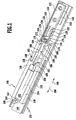
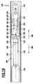
- Fig. 1
- eine schematische perspektivische Darstellung einer Auszugführung, die eine erste Führungsschiene mit einer daran angeordneten Rückhalteeinrichtung und eine zweite Führungsschiene mit einer daran angeordneten Sperreinrichtung und einem an der Sperreinrichtung gehaltenen Dämpfergehäuse umfasst;
- Fig. 2
- einen schematischen Längsschnitt durch die Auszugführung aus Fig. 1;
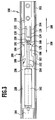
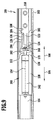
- Fig. 3
- eine schematische Seitenansicht der Auszugführung in einem Zustand, in dem das Dämpfergehäuse in einer Einschubrichtung relativ zu der Rückhalteeinrichtung bewegt wird und ein Kolbenstangenkopf einer Kolbenstange eines in dem Dämpfergehäuse verschiebbar geführten Kolbens gerade die Rückhalteelemente der Rückhalteeinrichtung erreicht hat;
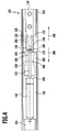
- Fig. 4
- eine der Fig. 3 entsprechende Darstellung der Auszugführung in einem Zustand, in dem der Kolbenstangenkopf die Rückhalteelemente von der Rückhaltestellung in die Freigabestellung bewegt, um die Rückhalteelemente passieren zu können;
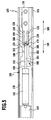
- Fig. 5
- eine der Fig. 4 entsprechende Darstellung der Auszugführung in einem Zustand, in welchem der Kolbenstangenkopf die Rückhalteelemente passiert hat und sich in einer Stoppstellung zwischen dem Anschlag und den Rückhaltelementen befindet, welche sich in die Rückhaltestellung zurückbewegt haben;
- Fig. 6
- eine der Fig. 5 entsprechende Darstellung der Auszugführung in einem Zustand , in welchem sich der Kolbenstangenkopf in der Stoppstellung befindet, während sich das Dämpfergehäuse weiter in der Einschubrichtung bewegt und Sperrelemente der Sperreinrichtung die Rückhalteelemente erreicht haben;
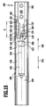
- Fig. 7
- eine der Fig. 6 entsprechende Darstellung der Auszugführung in einem Zustand, in welchem sich der Kolbenstangenkopf in der Stoppstellung befindet und das Dämpfergehäuse seine Endlage erreicht hat, in welcher die Kolbenstange maximal in das Dämpfergehäuse eingeschoben ist;
- Fig. 8
- eine der Fig. 6 entsprechende Darstellung der Auszugführung in einem Zustand, in welchem die Sperrelemente die Rückhalteelemente erreicht haben, ohne dass sich der Kolbenstangenkopf in der Stoppstellung befindet;
- Fig. 9
- eine der Fig. 8 entsprechende Darstellung der Auszugführung in einem Zustand, in dem der Kolbenstangenkopf sich an den Rückhalteelementen vorbeibewegt, welche in jeweils eine Ausnehmung der Sperreinrichtung ausweichen;
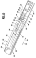
- Fig. 10
- eine schematische perspektivische Darstellung einer zweiten Ausführungsform der Auszugführung mit Bewegungsdämpfungsvorrichtung, deren Sperreinrichtung keine Ausnehmungen für das seitliche Ausweichen der Rückhalteelemente aufweist;
- Fig. 11
- einen schematischen Längsschnitt durch die zweite Ausführungsform einer Auszugführung aus Fig. 10;
- Fig. 12
- eine schematische Seitenansicht der zweiten Ausführungsform einer Auszugführung aus den Fig. 10 und 11 in einem Zustand, in dem der Kolbenstangenkopf die Rückhalteelemente unter elastischer Verformung derselben passiert, nachdem die Sperrelemente die Rückhalteelemente bereits erreicht haben;
- Fig. 13
- eine schematische perspektivische Darstellung einer dritten Ausführungsform einer Auszugführung mit Bewegungsdämpfungsvorrichtung, bei welcher die Rückhalteelemente in die Freigabestellung vorgespannt sind;
- Fig. 14
- einen schematischen Längsschnitt durch die dritte Ausführungsform einer Auszugführung aus Fig. 13;
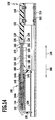
- Fig. 15
- eine schematische Seitenansicht der dritten Ausführungsform einer Auszugführung in einem Zustand, in dem der Kolbenstangenkopf gerade die in der Freigabestellung befindlichen Rückhalteelemente passiert;
- Fig. 16
- eine der Fig. 15 entsprechende Darstellung der dritten Ausführungsform einer Auszugführung in einem Zustand, in dem Anlaufschrägen der Sperrelemente die Rückhalteelemente erreicht haben und dieselben von der Freigabestellung in die Rückhaltestellung bewegen;
- Fig. 17
- eine der Fig. 16 entsprechende Darstellung der dritten Ausführungsform einer Auszugführung in einem Zustand, in welchem die Rückhalteelemente die Rückhaltestellung erreicht haben;
- Fig. 18
- eine der Fig. 17 entsprechende Darstellung der dritten Ausführungsform einer Auszugführung in einem Zustand, in welchem das Dämpfergehäuse seine Endlage erreicht hat und die Kolbenstange maximal in das Dämpfergehäuse eingeschoben ist;
- Fig. 19
- eine der Fig. 17 entsprechende Darstellung der dritten Ausführungsform einer Auszugführung in einem Zustand, in welchem die Sperrelemente die Rückhalteelemente bereits in die Rückhaltestellung bewegt haben, ohne dass sich der Kolbenstangenkopf in der Stoppstellung befindet;
- Fig. 20
- eine der Fig. 19 entsprechende Darstellung der dritten Ausführungsform einer Auszugführung in einem Zustand, in dem sich der Kolbenstangenkopf in der Einschubrichtung an den Rückhalteelementen vorbei bewegt, wobei die Rückhalteelemente in eine Ausnehmung der Sperreinrichtung ausweichen; und
- Fig. 21
- eine vergrößerte Darstellung des Kolbenstangenkopfes und der Rückhaltekrallen der zweiten Ausführungsform einer Auszugführung in einer Stoppstellung, in welcher eine Sperrfläche des Kolbenstangenkopfes an einem hinteren Ende jeder Rückhaltekralle anliegt.
- Fig. 1
- a schematic perspective view of an extension guide comprising a first guide rail with a retaining means disposed thereon and a second guide rail with a locking device arranged thereon and a damper housing held on the locking device;
- Fig. 2
- a schematic longitudinal section through the pullout guide of FIG. 1;
- Fig. 3
- a schematic side view of the pullout guide in a state in which the damper housing is moved in a direction of insertion relative to the retainer and a piston rod head of a piston rod of a displaceably guided in the damper housing piston has just reached the retaining elements of the retainer;
- Fig. 4
- a view corresponding to Figure 3 of the pullout guide in a state in which the piston rod head moves the retaining elements from the retaining position to the release position to pass the retaining elements can;
- Fig. 5
- a view corresponding to Figure 4 of the pullout guide in a state in which the piston rod head has passed the retaining elements and is in a stop position between the stop and the retaining elements, which have moved back into the retaining position.
- Fig. 6
- a view corresponding to Figure 5 of the pullout guide in a state in which the piston rod head is in the stop position, while the damper housing moves further in the insertion direction and locking elements of the locking device have reached the retaining elements.
- Fig. 7
- one of Figure 6 corresponding representation of the pullout guide in a state in which the piston rod head is in the stop position and the damper housing has reached its end position in which the piston rod is pushed into the maximum damper housing.
- Fig. 8
- a view corresponding to Figure 6 of the pullout guide in a state in which the locking elements have reached the retaining elements, without that the piston rod head is in the stop position.
- Fig. 9
- a view corresponding to Figure 8 of the pullout guide in a state in which the piston rod head moves past the retaining elements, which yield in each case a recess of the locking device;
- Fig. 10
- a schematic perspective view of a second embodiment of the pullout guide with motion damping device whose locking device has no recesses for the lateral deflection of the retaining elements;
- Fig. 11
- a schematic longitudinal section through the second embodiment of an extension guide of FIG. 10;
- Fig. 12
- a schematic side view of the second embodiment of an extract guide of Figures 10 and 11 in a state in which the piston rod head, the retaining elements under elastic deformation thereof passes after the locking elements have already reached the retaining elements.
- Fig. 13
- a schematic perspective view of a third embodiment of an extension guide with motion damping device, in which the retaining elements are biased in the release position;
- Fig. 14
- a schematic longitudinal section through the third embodiment of an extension guide of FIG. 13;
- Fig. 15
- a schematic side view of the third embodiment of an extension guide in a state in which the piston rod head just passed the located in the release position retaining elements;
- Fig. 16
- a representation corresponding to FIG. 15 of the third embodiment of an extension guide in a state in which run-on slopes of the locking elements have reached the retaining elements and move them from the release position into the retaining position;
- Fig. 17
- a representation corresponding to FIG. 16 of the third embodiment of an extension guide in a state in which the retaining elements have reached the retaining position;
- Fig. 18
- 17 shows a representation corresponding to the third embodiment of an extension guide in a state in which the damper housing has reached its end position and the piston rod is inserted maximally into the damper housing;
- Fig. 19
- 17 shows a representation corresponding to FIG. 17 of the third embodiment of an extension guide in a state in which the locking elements have already moved the retaining elements into the retaining position without the piston rod head being in the stop position;
- Fig. 20
- 19 shows a representation corresponding to the third embodiment of an extension guide in a state in which the piston rod head moves in the direction of insertion past the retaining elements, wherein the retaining elements escape into a recess of the locking device; and
- Fig. 21
- an enlarged view of the piston rod head and the retaining claws of the second embodiment of an extension guide in a stop position in which a locking surface of the piston rod head abuts a rear end of each retaining claw.
Gleiche oder funktional äquivalente Elemente sind in allen Figuren mit denselben Bezugszeichen bezeichnet.Identical or functionally equivalent elements are denoted by the same reference numerals in all figures.
Eine in den Fig. 1 bis 9 dargestellte und als Ganzes mit 100 bezeichnete Auszugführung umfasst eine erste Führungsschiene 102 und eine zweite Führungsschiene 104, welche mittels einer (nicht dargestellten) Wälzkörperanordnung längs einer Auszugrichtung 106 und einer entgegengesetzt zu der Auszugrichtung 106 gerichteten Einschubrichtung 108 relativ zu der ersten Führungsschiene 102 verschiebbar an der ersten Führungsschiene 102 gehalten ist.A pullout guide shown in FIGS. 1 to 9 and designated as a whole by 100 comprises a
Die erste Führungsschiene 102 kann beispielsweise an einem Korpus eines Möbels und die zweite Führungsschiene 104 beispielsweise an einem Auszug des Möbels angeordnet werden.The
Genauso gut könnte aber auch die erste Führungsschiene 102 an dem Auszug und die zweite Führungsschiene 104 an dem Korpus des Möbels angeordnet werden.But just as well, the
Ferner könnte die Auszugführung 100 auch noch weitere Führungsschienen umfassen, welche verschiebbar an der ersten Führungsschiene 102 oder an der zweiten Führungsschiene 104 oder aber zwischen der ersten Führungsschiene 102 und der zweiten Führungsschiene 104 gehalten sind.Furthermore, the
Wie aus den Fig. 1 und 2 zu ersehen ist, ist an der ersten Führungsschiene 102 ein Sockel 110 in Form einer Profilleiste mit einem U-förmigen Querschnitt angeordnet. Ein an der ersten Führungsschiene 102 anliegender erster Schenkel 112 des Sockels 110 ist mittels mehrerer Befestigungsschrauben 114 an der ersten Führungsschiene 102 gehalten.As can be seen from FIGS. 1 and 2, a base 110 in the form of a profiled strip with a U-shaped cross section is arranged on the
Ein der ersten Führungsschiene 102 abgewandter zweiter Schenkel 116 trägt eine als Ganzes mit 118 bezeichnete Rückhalteeinrichtung, die mittels mehrerer Befestigungsschrauben 120 lösbar an dem Sockel 110 festgelegt ist.One of the
Die Rückhalteeinrichtung 118 umfasst eine im wesentlichen quaderförmige Basis 122, welche mit gestuften Durchtrittsöffnungen 124 für die Befestigungsschrauben 120 versehen ist und sich längs der Auszugrichtung 106 erstreckt.The retaining
Von der vorderen Stirnseite der Basis 122 stehen zwei Rückhalteelemente 126 längs der Auszugrichtung 106 nach vorne ab, welche jeweils einen sich parallel zur Auszugrichtung 106 erstreckenden Krallenarm 128 und eine Rückhaltekralle 130 umfassen, wobei sich die Rückhaltekralle 130 vom vorderen Ende des jeweiligen Krallenarms 128 aus nach innen, d. h. zur Längsmittelebene der Rückhalteeinrichtung 118 hin, und nach hinten, d. h. zu der Basis 122 der Rückhalteeinrichtung 118 hin, erstrecken. Die freien Enden der Rückhaltekrallen 130 sind voneinander beabstandet.From the front end face of the base 122 are two retaining
Zwischen den Krallenarmen 128 ist an der Rückhalteeinrichtung 118 ein Anschlagvorsprung 132 ausgebildet, welcher von der vorderen Stirnseite der Basis 122 aus längs der Auszugrichtung 106 vorspringt und dessen vordere Stirnfläche eine Anschlagfläche 134 bildet.Between the
Die Krallenarme 128 der Rückhalteelemente 126 weisen eine Formelastizität auf, die es ermöglicht, dass sich die vorderen Endbereiche der Rückhalteelemente 126 unter Verbreiterung des Durchlasses zwischen den Rückhaltekrallen 130 auseinanderbewegen.The
Ohne Einwirkung einer äußeren Kraft befinden sich die Rückhalteelemente 126 aufgrund ihrer Formelastizität in der in den Fig. 1 und 3 dargestellten Rückhaltestellung.Without the action of an external force, the retaining
Die die Basis 122, den Anschlagvorsprung 132 und die Rückhaltelemente 126 umfassende Rückhalteeinrichtung 118 ist einstückig aus einem geeigneten elastischen Kunststoffmaterial gebildet, während der Sockel 110 und die Führungsschienen 102, 104 vorzugsweise aus einem metallischen Material gebildet sind.The
Die Rückhalteeinrichtung 118 kann insbesondere als Spritzgießteil ausgebildet sein.The retaining
Die Rückhalteeinrichtung 118 wirkt in einer später noch näher zu beschreibenden Weise mit einer als Ganzes mit 136 bezeichneten Sperreinrichtung zusammen, die einen im wesentlichen rechteckigen Halterahmen 138 umfasst, welcher an seiner Unterseite mittels Rastfüßen 140 mit Durchgangsöffnungen in der zweiten Führungsschiene 104 verrastet ist.The retaining
Der Innenraum des Halterahmens 138 bildet eine Aufnahme für ein im wesentlichen hohlzylindrisches Dämpfergehäuse 142.The interior of the holding
Wie aus Fig. 2 zu ersehen ist, umschließt das Dämpfergehäuse 142 einen beispielsweise im wesentlichen zylindrischen Innenraum 144, in welchem ein Bewegungsdämpfungsfluid, beispielsweise ein Öl, angeordnet ist.As can be seen from Fig. 2, the
In den mit dem Bewegungsdämpfungsfluid befüllten Innenraum 144 des Dämpfergehäuses 142 taucht ein Kolben 146 ein, der einen innerhalb des Innenraums 144 angeordneten Kolbenkopf 148 und eine aus dem Innenraum 144 durch eine Rückwand 150 des Dämpfergehäuses 142 fluiddicht hindurchgeführte Kolbenstange 152 umfasst.Into the
Der Querschnitt des Kolbenkopfs 148 entspricht im wesentlichen dem Querschnitt des Innenraums 144.The cross section of the
Der Kolbenkopf 148 ist mit Strömungskanälen 153 versehen, durch welche das Bewegungsdämpfungsfluid aus dem vor dem Kolbenkopf 148 liegenden Bereich 144a des Innenraums 144 in den hinter dem Kolbenkopf 148 liegenden Bereich 144b des Innenraums 144 bzw. in umgekehrter Richtung durch den Kolbenkopf 148 hindurchströmen kann, und zwar unter Überwindung eines erheblichen Strömungswiderstandes sowie unter Überwindung der Reibung zwischen dem Kolbenkopfmantel und der Innenwand des Dämpfergehäuses 142.The
Der Kolben 146 ist als Ganzes in seiner Längsrichtung 154 relativ zu dem Dämpfergehäuse 142 verschiebbar an dem Dämpfergehäuse 142 geführt.The
Die Kolbenstange 152 durchsetzt eine Rastaufnahme 156 in einer hinteren Stirnwand 158 des Halterahmens 138, in welcher die Kolbenstange 152 so aufgenommen ist, dass sie in ihrer Axialrichtung relativ zu dem Halterahmen 138 verschiebbar, aber gegen ein Herausbewegen nach oben aus der Rastaufnahme 156 heraus gesichert ist.The
Das Dämpfergehäuse 142 ist ferner an seinem vorderen Ende mit einem im wesentlichen zylindrischen Vorsprung 160 versehen, der so in einer Rastaufnahme 162 einer vorderen Stirnwand 164 des Halterahmens 138 aufgenommen ist, dass er gegen ein Herausbewegen nach oben aus der Rastaufnahme 162 heraus gesichert ist.The
Die vordere Stirnfläche und die hintere Stirnfläche des Dämpfergehäuses 142 liegen so an der vorderen Stirnwand 164 bzw. an der hinteren Stirnwand 158 des Halterahmens 138 an, dass das Dämpfergehäuse 142 gegen eine Bewegung in seiner Axialrichtung relativ zu dem Halterahmen 138 und somit relativ zu der Sperreinrichtung 136 gesichert ist.The front end face and the rear end face of the
An ihrem dem Kolbenkopf 148 abgewandten Ende endet die Kolbenstange 152 an einem Kolbenstangenkopf 166, welcher durch einen Abschnitt 168 geringeren Durchmessers von dem kolbenkopfseitigen Teil der Kolbenstange 152 getrennt ist. Im Bereich des Abschnitts 168 ist die Kolbenstange 152 somit mit einer Einschnürung 170 versehen.At its end facing away from the
Der Kolbenstangenkopf 166 umfasst einen sich an den Abschnitt 168 der Kolbenstange 152 anschließenden kegelstumpfförmigen vorderen Abschnitt 172, einen sich an den vorderen Abschnitt 172 anschließenden zylindrischen mittleren Abschnitt 174 und einen sich an den mittleren Abschnitt 174 anschließenden kegelstumpfförmigen hinteren Abschnitt 176, an welchem die Kolbenstange 152 endet.The
Die Oberfläche des hinteren Abschnitts 176 bildet eine kegelstumpfmantelförmige Anlaufschräge 178, mit weicher der Kolbenstangenkopf 166 gegen die Rückhalteelemente 126 der Rückhalteeinrichtung 118 anläuft, wenn sich die Kolbenstange 152 in der Einschubrichtung 108 gegen die Rückhalteeinrichtung 118 bewegt.The surface of the
Die kegelstumpfmantelförmige Oberfläche des vorderen Abschnitts 172 des Kolbenstangenkopfes 166 bildet eine Sperrfläche 180, mit welcher der Kolbenstangenkopf 166 in einer später noch genauer zu beschreiben Stoppstellung an den Rückhaltekrallen 130 der Rückhalteeinrichtung 118 anliegt.The truncated cone-shaped surface of the
Die Sperrfläche 180 ist stärker gegen die Längsrichtung 154 des Kolbens 146 geneigt als die Anlaufschräge 178.The blocking
Zu beiden Seiten der Kolbenstange 152 steht von der hinteren Stirnwand 158 des Halterahmens 138 der Sperreinrichtung 136 jeweils ein Sperrelement 182 in der Einschubrichtung 108 nach hinten vor. Jedes der Sperrelemente 182 ist an seinem hinteren Ende mit einer Anlaufschräge 184 versehen.On both sides of the
An diese Anlaufschräge 184 schließt sich nach vorne jeweils eine Anlagefläche 186 an, welche im wesentlichen parallel zur Auszugrichtung 106 bzw. zur Einschubrichtung 108 ausgerichtet ist.To this run-
Zwischen dem vorderen Ende der Anlagefläche 186 und der hinteren Stirnwand 158 des Halterahmens 138 ist an jedem der Sperrelemente 182 jeweils eine im Querschnitt im wesentlichen rechteckige Ausnehmung 188 vorgesehen.Between the front end of the
Die den Halterahmen 138 und die Sperrelemente 182 umfassende Sperreinrichtung 136 ist vorzugsweise einstückig aus einem geeigneten Material, vorzugsweise aus einem Kunststoffmaterial, hergestellt.The
Das Kunststoffmaterial wird dabei so gewählt, dass die Sperrelemente 182 nicht oder nur in geringem Maße elastisch verformbar sind.The plastic material is chosen so that the locking
Die Sperreinrichtung 136 kann insbesondere als ein Spritzgießteil aus einem Kunststoffmaterial hergestellt sein.The
Die Sperreinrichtung 136 mit dem Dämpfergehäuse 142 und dem Kolben 146 sowie die Rückhalteeinrichtung 118 bilden zusammen eine Bewegungsdämpfungsvorrichtung 190 der Auszugführung 100.The
Die Funktion der vorstehend beschriebenen Bewegungsdämpfungsvorrichtung 190 wird im folgenden unter Bezugnahme auf die Fig. 3 bis 9 im einzelnen beschrieben:The function of the
Wenn die zweite Führungsschiene 104 mit dem Dämpfergehäuse 142 relativ zu der ersten Führungsschiene 102 aus ihrer ausgezogenen Stellung längs der Einschubrichtung 108 in ihre eingeschobene Stellung bewegt wird, so bewegt sich der Kolben 146 mit der Kolbenstange 152 aufgrund des für eine Relativbewegung zwischen dem Kolben 146 und dem Dämpfergehäuse 142 zu überwindenden großen Strömungswiderstandes zunächst zusammen mit dem Dämpfergehäuse 142 in der Einschubrichtung 108, bis der in Fig. 3 dargestellte Zustand erreicht ist, in dem der Kolbenstangenkopf 166 gegen die Rückhaltekrallen 130 der Rückhalteelemente 126 der Rückhalteeinrichtung 118 läuft, deren dem Dämpfergehäuse 142 zugewandte Vorderseiten jeweils eine Anlaufschräge 192 für den Kolbenstangenkopf 166 bilden.When the
Bewegt sich nun das Dämpfergehäuse 142 mit der Kolbenstange 152 weiter in der Einschubrichtung 108, so wandern die Rückhaltekrallen 130 längs der Anlaufschräge 178 des Kolbenstangenkopfs 166 nach außen, wodurch die Krallenarme 128 auseinandergespreizt werden und die Rückhalteelemente 126 in ihre Freigabestellung bewegt werden, in welcher der Kolbenstangenkopf 166 die Rückhaltekrallen 138 passieren kann (siehe Fig. 4).Moves now the
Nachdem der Kolbenstangenkopf 166 die Rückhaltekrallen 130 passiert hat, wandern die Rückhaltekrallen 130 bei Fortsetzung der Bewegung des Dämpfergehäuses 142 längs der Einschubrichtung 108 entlang der Sperrfläche 180 des Kolbenstangenkopfes 166 wieder nach innen, bis die Rückhaltekrallen 130 in die Einschnürung 170 der Kolbenstange 152 eingreifen und die Rückhalteelemente 126 sich wieder in der Rückhaltestellung befinden (siehe Fig. 5). Zugleich schlägt die vordere Stirnfläche des Kolbenstangenkopfes 166 an der Anschlagfläche 134 des Anschlagvorsprungs 132 an, so dass die Bewegung der Kolbenstange 152 längs der Einschubrichtung 108 in einer Stoppstellung gestoppt wird.After the
Bewegt sich nun das Dämpfergehäuse 142 weiter in der Einschubrichtung 108, so kann der Kolben 146 dieser Bewegung nicht mehr folgen, was zur Folge hat, dass die Kolbenstange 152 in das Dämpfergehäuse 142 hineingeschoben wird (siehe Fig. 6).If now the
Hierdurch bewegt sich der Kolbenkopf 148 im Innenraum 144 des Dämpfergehäuses 142 nach vorne. Das bei dieser Relativbewegung zwischen dem Kolben 146 und dem Dämpfergehäuse 142 aus dem Bereich 144a des Innenraums verdrängte Volumen des Bewegungsdämpfungsfluids strömt durch die Strömungskanäle 153 im Kolbenkopf 148 in den Bereich 144b des Innenraums. Aufgrund des hierbei zu überwindenden Strömungswiderstands in den engen Strömungskanälen 153 und der Reibung zwischen dem Kolbenkopf 148 und der Innenwand des Dämpfergehäuses 142 wird eine Bremskraft verursacht, welche die Bewegung des Dämpfergehäuses 142 und somit die Bewegung der zweiten Führungsschiene 104 längs der Einschubrichtung 108 abbremst.As a result, the
Diese gebremste Bewegung längs der Einschubrichtung 108 setzt das Dämpfergehäuse 142 fort, bis die zweite Führungsschiene 104 ihren (nicht dargestellten) Endanschlag an der ersten Führungsschiene 102 erreicht und zusammen mit dem Dämpfergehäuse 142 in der in Fig. 7 dargestellten Endlage zur Ruhe kommt.This braked movement along the direction of
Wie aus den Fig. 6 und 7 zu ersehen ist, erreichen, nachdem der Kolbenstangenkopf 166 in der Stoppstellung angekommen ist, die Sperrelemente 182 der Sperreinrichtung 136 die Rückhalteelemente 126 und legen sich mit ihren Anlageflächen 186 flächig an die dem Anschlagvorsprung 132 abgewandten Außenseiten 194 der Krallenarme 128 an. Dabei wird durch die Anlaufschrägen 184 an den vorderen Enden der Sperrelemente 182 erreicht, dass die Rückhalteelemente 126 auch dann in den Bereich zwischen den Sperrelementen 182 gelangen, wenn sie nach dem Passieren des Kolbenstangenkopfs 166 noch etwas auseinandergespreizt sein sollten.As can be seen from Figs. 6 and 7, reach after the
Solange die Sperrelemente 182 von außen an den Rückhalteelementen 126 anliegen, können sich die Krallenarme 128 nicht auseinanderbiegen, und somit wird eine Rückkehr der Rückhalteelemente 126 in die Freigabestellung durch die Sperrelemente 182 verhindert. Dadurch kann der Kolbenstangenkopf 166 sich zunächst nicht zwischen den Rückhaltekrallen 130 hindurch längs der Auszugrichtung 106 bewegen, wenn die zweite Führungsschiene 104 mit dem Dämpfergehäuse 142 relativ zu der ersten Führungsschiene 102 wieder längs der Auszugrichtung 106 ausgezogen wird. Vielmehr liegt der Kolbenstangenkopf 166 mit seiner Sperrfläche 180 an den freien Enden der Rückhaltekrallen 130 an und wird somit durch die Rückhalteelemente 126 in der Stoppstellung zurückgehalten, während sich das Dämpfergehäuse 142 in der Auszugrichtung 106 von dem Kolbenstangenkopf 166 wegbewegt. Hierdurch wird die Kolbenstange 152 wieder aus dem Dämpfergehäuse 142 herausgezogen, bis die sich mit dem Dämpfergehäuse 142 in der Auszugrichtung 106 bewegenden Sperrelemente 182 von den Rückhalteelementen 126 lösen, so dass sich die Rückhalteelemente 126 durch Auseinanderspreizen der Krallenarme 128 wieder in die Freigabestellung bewegen können, worauf der Kolbenstangenkopf 166 den Durchlass zwischen den Rückhaltekrallen 130 passieren kann und bei weiterem Ausziehen der zweiten Führungsschiene 104 in der Auszugrichtung 106 wieder mit dem Dämpfergehäuse 142 mitbewegt wird.As long as the locking
Der maximale Auszugweg, um welchen die Kolbenstange 152 beim Ausziehen der zweiten Führungsschiene 104 aus dem Dämpfergehäuse 142 herausgezogen wird, und somit die Länge des Dämpfungsweges der Bewegungsdämpfungsvorrichtung 190 wird also durch die Strecke s bestimmt, um welche der hintere Rand der Anlagefläche 186 der Sperrelemente 182 in der in Fig. 7 dargestellten Endlage hinter dem vorderen Ende der Rückhalteelemente 126 liegt.The maximum extension travel, by which the
Diese Strecke kann bei einer Variante der Bewegungsdämpfungsvorrichtung 190 dadurch variiert werden, dass die Sperrelemente 182 nicht einstückig mit dem Halterahmen 138 der Sperreinrichtung 136 ausgebildet sind, sondern lösbar an dem Halterahmen 138 in verschiedenen, in der Längsrichtung 154 voneinander beabstandeten Positionen festlegbar sind.In a variant of the
Auf diese Weise ist es möglich, ein und denselben Bewegungsdämpfer mit unterschiedlichen Dämpfungswegen einzusetzen, in Abhängigkeit von unterschiedlichen an der Auszugführung 100 anzuordnenden Lasten oder in Abhängigkeit von unterschiedlichen, beim Einschieben der zweiten Führungsschiene 104 auftretenden Geschwindigkeiten.In this way it is possible to use one and the same motion damper with different damping paths, depending on different loads to be arranged on the
Im Betrieb der Auszugführung 100 kann auch der Fall eintreten, dass sich die Kolbenstange 152 in ihrer maximal in das Dämpfergehäuse 142 eingeschobenen Stellung befindet, ohne dass der Kolbenstangenkopf 166 bereits in der Stoppstellung hinter den Rückhaltekrallen 130 angelangt ist, wie dies in Fig. 8 dargestellt ist. Auch in einer solchen Ausnahmesituation muss der Kolbenstangenkopf 166 beim weiteren Einschieben der zweiten Führungsschiene 104 und des Dämpfergehäuses 142 in der Einschubrichtung 108 an den Rückhaltekrallen 130 vorbei in die Stoppstellung bewegt werden können, damit die Kolbenstange 152 beim nächsten Ausziehvorgang wieder ordnungsgemäß aus dem Dämpfergehäuse 142 herausgezogen werden kann.During operation of the pull-
Um diese Notfunktion der Bewegungsdämpfungsvorrichtung 190 zu gewährleisten, sind die Ausnehmungen 188 an den Sperrelementen 182 vorgesehen. Wie aus Fig. 9 zu ersehen ist, können nämlich die Rückhalteelemente 126 in diese Ausnehmungen 188 hinein ausweichen, wenn der Kolbenstangenkopf 166 bei maximal in das Dämpfergehäuse 142 eingeschobener Kolbenstange 152 die Rückhaltekrallen 130 erreicht, so dass der Kolbenstangenkopf 166 die Rückhaltekrallen 130 seitlich verdrängen und zwischen denselben hindurch in die Stoppstellung gelangen kann (siehe Fig. 9).To ensure this emergency function of the
Eine in den Fig. 10 bis 12 und 21 dargestellte zweite Ausführungsform der Auszugführung 100 unterscheidet sich von der in den Fig. 1 bis 9 dargestellten ersten Ausführungsform lediglich dadurch, dass die Sperrelemente 182 der Sperreinrichtung 136 nicht mit den Ausnehmungen 188 versehen sind, sondern sich in im wesentlichen gleicher Breite von der hinteren Stirnwand 158 des Halterahmens 138 bis zu dem hinteren Rand der Anlagefläche 186 erstrecken.A second embodiment of the
Wie am besten aus Fig. 12 zu ersehen ist, ist die vorstehend in Bezug auf die erste Ausführungsform erläuterte Notfunktion bei dieser Ausführungsform dadurch gewährleistet, dass die Rückhaltekrallen 130 der Rückhaltelemente 126 bei in der Rückhaltestellung befindlichen Rückhalteelementen 126 so elastisch verformbar sind, dass der Kolbenstangenkopf 166 die freien Enden der Rückhaltekrallen 130 auseinanderdrücken und durch den Durchlass zwischen den Rückhaltekrallen 130 in die Stoppstellung zwischen den Rückhaltekrallen 130 und dem Anschlagvorsprung 132 gelangen kann.As best seen in FIG. 12, the emergency function discussed above with respect to the first embodiment is ensured in this embodiment by elastically deforming the
Insbesondere ist der Verbindungsbereich der Rückhaltekrallen 130, mit welchem die Rückhaltekrallen 130 mit dem jeweils zugeordneten Krallenarm 128 verbunden sind, so elastisch verformbar, dass jede der Rückhaltekrallen 130 quer zu ihrer jeweiligen Längsrichtung 198 (siehe Fig. 21) um den Verbindungsbereich verschwenkbar ist, um den Kolbenstangenkopf 166 zwischen den freien Enden der Rückhaltekrallen 130 passieren zu lassen.In particular, the connecting portion of the retaining
Die Beweglichkeit der Rückhaltekrallen 130 relativ zu dem jeweils zugeordneten Krallenarm 128 kann auch dadurch erreicht werden, dass jede Rückhaltekralle 130 über ein Gelenk mit dem jeweils zugeordneten Krallenarm 128 verbunden ist.The mobility of the retaining
Um zu verhindern, dass der Kolbenstangenkopf 166 aus der in Fig. 21 dargestellten Stoppstellung, in welcher die Sperrfläche 180 des Kolbenstangenkopfes an den freien Enden der Rückhaltekrallen 130 anliegt, unbeabsichtigt zwischen den Rückhaltekrallen 130 hindurch in der Auszugrichtung 106 bewegt wird, sind die Rückhalteelemente 126 vorzugsweise so ausgebildet, dass in dieser Stoppstellung des Kolbenstangenkopfes 166 die Längsrichtung 198 jeder Rückhaltekralle 130 mit der lokalen Flächennormale 200 der Sperrfläche 180 des Kolbenstangenkopfes 166 an derjenigen Stelle, an welcher die Sperrfläche 180 an dem freien Ende der Rückhaltekralle 130 anliegt, einen spitzen Winkel von höchstens ungefähr 45°, vorzugsweise von höchstens ungefähr 20°, insbesondere von im wesentlichen 0° (wie in Fig. 21 dargestellt), einschließt. Hierdurch ist gewährleistet, dass in dieser Stoppstellung nur eine geringe oder vorzugsweise gar keine senkrecht zu der Längsrichtung 198 der jeweiligen Rückhaltekralle 130 wirkende Kraft von der Sperrfläche 180 auf die Rückhaltekralle 130 übertragen wird und somit kein die jeweilige Rückhaltekralle 130 aus ihrer in Fig. 21 dargestellten Rückhaltestellung in die Freigabestellung, in weicher der Kolbenstangenkopf 166 zwischen den freien Enden der Rückhaltekrallen 130 hindurch bewegt werden kann, bewegendes Drehmoment auf die Rückhaltekralle 130 einwirkt.In order to prevent the
Im übrigen stimmt die in den Fig. 10 bis 12 dargestellte zweite Ausführungsform hinsichtlich Aufbau und Funktion mit der ersten Ausführungsform überein, auf deren vorstehende Beschreibung insoweit Bezug genommen wird.Incidentally, the second embodiment shown in FIGS. 10 to 12 is identical in structure and function to the first embodiment, to the above description of which reference is made.
Eine in den Fig. 13 bis 20 dargestellte dritte Ausführungsform einer Auszugführung 100 mit Bewegungsdämpfungsvorrichtung 190 unterscheidet sich von der in den Fig. 1 bis 9 dargestellten ersten Ausführungsform dadurch, dass sich die Rückhalteelemente 126 der Rückhalteeinrichtung 118 in ihrer Ruhestellung, in welcher keine externe Kraft auf die Rückhalteelemente 126 einwirkt, nicht, wie bei der ersten Ausführungsform, in der Rückhaltestellung, sondern vielmehr in der Freigabestellung befinden. Somit muss der Kolbenstangenkopf 166 beim Passieren der Rückhaltekrallen 130 dieselben nicht erst auseinanderdrücken, und die Rückhattetemente 126 werden erst dann in die Rückhaltestellung bewegt, in welcher die Rückhaltekrallen 130 in die Einschnürung 170 vor dem Kolbenstangenkopf 166 eingreifen, wenn die vorderen Enden der Rückhalteelemente 126 von den Sperrelementen 182 erreicht werden.A third embodiment shown in FIGS. 13 to 20 of an
Ferner sind die Ausnehmungen 188 an den Sperrelementen 182, in welche die Rückhalteelemente 126 ausweichen können, bei dieser Ausführungsform nicht wie bei der ersten Ausführungsform mit einem längs der Auszugrichtung 106 konstanten Querschnitt versehen, sondern vielmehr erweitern sich diese Ausnehmungen 188 von ihrem hinteren Ende aus bis hin zu der hinteren Stirnwand 158 des Halterahmens 138, so dass diese Ausnehmungen 188 in der in Fig. 15 dargestellten Seitenansicht der Sperreinrichtung 136 einen im wesentlichen dreieckigen Querschnitt aufweisen.Further, the
Ferner sind die Sperrelemente 182 an ihren der Kolbenstange 152 abgewandten Außenseiten mit jeweils einer Ausnehmung 196 versehen, welche sich vom hinteren Ende des betreffenden Sperrelements 182 bis nahezu zu der hinteren Stirnwand 158 des Halterahmens 138 erstreckt.Further, the locking
Im übrigen stimmt diese dritte Ausführungsform hinsichtlich ihres Aufbaus mit der vorstehend beschriebenen ersten Ausführungsform überein.Incidentally, this third embodiment is consistent in construction with the first embodiment described above.
Die Funktion dieser dritten Ausführungsform wird im folgenden unter Bezugnahme auf die Fig. 15 bis 20 im einzelnen beschrieben:The operation of this third embodiment will be described in detail below with reference to Figs. 15 to 20.
Wenn die zweite Führungsschiene 104 mit dem Dämpfergehäuse 142 relativ zu der ersten Führungsschiene 102 aus ihrer ausgezogenen Stellung längs der Einschubrichtung 108 in ihre eingeschobene Stellung bewegt wird, so bewegt sich der Kolbenstangenkopf 166 der mit dem Dämpfergehäuse 142 mitbewegten Kolbenstange 152 ebenfalls längs der Einschubrichtung 108 zwischen den Rückhaltekrallen 130 hindurch, bis der Kolbenstangenkopf 166 mit seiner hinteren Stirnfläche an der Anschlagfläche 134 des Anschlagvorsprungs 132 anschlägt (siehe Fig. 15 und 16).When the
Da die Krallenarme 128 der Rückhalteelemente 126 in der Ruhestellung nicht parallel zueinander ausgerichtet sind, sondern eine kleinen spitzen Winkel miteinander einschließen und somit leicht auseinandergespreizt sind, weisen die einander zugewandten Enden der Rückhaltekrallen 130 einen Abstand voneinander auf, welcher mindestens dem Durchmesser des mittleren Abschnitts 174 des Kolbenstangenkopfes 166 entspricht, so dass der Kolbenstangenkopf 166 die Rückhaltekrallen 130 nicht auseinanderbewegen muss, um in die Stoppstellung hinter den Rückhaltekrallen 130 zu gelangen.Since the
Erst wenn die hinteren Enden der Sperrelemente 182 die vorderen Enden der Rückhalteelemente 126 erreichen, werden die Rückhalteelemente 126 von den Sperrelementen 182 in die Rückhaltesteilung bewegt, wobei die vorderen Enden der Rückhalteelemente 126 zunächst an den Anlaufschrägen 184 der Sperrelemente 182 nach innen abgleiten, um die Sperrelemente 182 an der Außenseite der Rückhalteelemente 126 passieren zu lassen.Only when the rear ends of the locking
Sobald die Anlageflächen 186 der Sperrelemente 182 von außen an den Außenseiten 194 der Rückhalteelemente 126 anliegen, sind die Rückhalteelemente 126 an einer Rückkehr in die Freigabestellung gehindert. In dieser Rückhaltestellung greifen die Rückhaltekrallen 130 in die Einschnürung 170 vor dem Kolbenstangenkopf 166 ein (siehe Fig. 17).Once the abutment surfaces 186 of the locking
Beim Weiterbewegen des Dämpfergehäuses 142 in der Einschubrichtung 108 wird die Kolbenstange 152 weiter in das Dämpfergehäuse 142 eingeschoben, bis die in Fig. 18 dargestellte Endlage erreicht ist, in welcher die Kolbenstange 152 maximal in das Dämpfergehäuse 142 eingeschoben ist.As the
Solange die Sperrelemente 182 von außen an den Rückhaltelementen 126 anliegen, können sich die Krallenarme 128 nicht auseinanderbiegen, und somit wird eine Rückkehr der Rückhalteelemente 126 in die Freigabestellung durch die Sperrelemente 182 verhindert. Dadurch wird der Kolbenstangenkopf 166 zunächst in der Stoppstellung hinter den Rückhaltekrallen 130 zurückgehalten, wenn die zweite Führungsschiene 104 mit dem Dämpfergehäuse 142 relativ zu der ersten Führungsschiene 102 wieder längs der Auszugrichtung 106 ausgezogen wird.As long as the locking
Sobald die sich mit dem Dämpfergehäuse 142 in der Auszugrichtung 106 bewegenden Sperrelemente 182 sich von den Rückhalteelementen 126 lösen, kehren die Rückhalteelemente 126 aufgrund ihrer Formelastizität in die Freigabestellung zurück, worauf der Kolbenstangenkopf 166 den Durchlass zwischen den Rückhaltekrallen 130 passieren kann und bei weiterem Ausziehen der zweiten Führungsschiene 104 in der Auszugrichtung 106 wieder mit dem Dämpfergehäuse 142 mitbewegt wird.As soon as the locking
Der Dämpfungsweg der Bewegungsdämpfungsvorrichtung 190, d. h. der maximale Auszugweg, um welchen die Kolbenstange 152 beim Ausziehen der zweiten Führungsschiene 104 aus dem Dämpfergehäuse 142 herausgezogen wird, wird somit auch bei dieser Ausführungsform durch die Strecke s bestimmt, um welche der hintere Rand der Anlagefläche 186 der Sperrelemente 182 in der in Fig. 18 dargestellten Endlage hinter dem vorderen Ende der Rückhaltelemente 126 liegt.The damping travel of the
Im Betrieb der Auszugführung 100 kann auch der Fall eintreten, dass sich die Kolbenstange 152 in ihrer maximal in das Dämpfergehäuse 142 eingeschobenen Stellung befindet, ohne dass der Kolbenstangenkopf 166 bereits in der Stoppstellung hinter den Rückhaltekrallen 130 angelangt ist, wie dies in Fig. 19 dargestellt ist. Um auch in einer solchen Ausnahmesituation zu gewährleisten, dass der Kolbenstangenkopf 166 beim weiteren Einschieben der zweiten Führungsschiene 104 und des Dämpfergehäuses 142 in der Einschubrichtung 108 an den Rückhaltekrallen 130 vorbei in die Stoppstellung bewegt werden kann, damit die Kolbenstange 152 beim nächsten Ausziehvorgang wieder ordnungsgemäß aus dem Dämpfergehäuse 142 herausgezogen werden kann, sind die Ausnehmungen 188 an den Sperrelementen 182 vorgesehen, in welche die Rückhalteelemente 126 hinein ausweichen können, wenn der Kolbenstangenkopf 166 bei maximal in das Dämpfergehäuse 142 eingeschobener Kolbenstange 152 die Rückhaltekrallen 130 erreicht, so dass der Kolbenstangenkopf 166 die Rückhaltekrallen 130 unter elastischer Verformung der Krallenarme 128 seitlich verdrängen und zwischen den Rückhaltekrailen 130 hindurch in die Stoppstellung gelangen kann (siehe Fig. 20).During operation of the pull-
Im übrigen stimmt die in den Fig. 13 bis 20 dargestellte dritte Ausführungsform mit der in den Fig. 1 bis 9 dargestellten Ausführungsform überein, auf deren vorstehende Beschreibung insoweit Bezug genommen wird.For the rest, the third embodiment shown in FIGS. 13 to 20 is identical to the embodiment shown in FIGS. 1 to 9, to the extent of which the above description is made.
Claims (26)
dadurch gekennzeichnet,
dass die Rückhalteeinrichtung (118) mindestens ein Rückhalteelement (126) umfasst, welches in einer Rückhaltestellung einen Endbereich der Kolbenstange (152) so hintergreift, dass die Kolbenstange (152) daran gehindert ist, der Bewegung des Dämpfergehäuses (142) zu folgen, und in einer Freigabestellung den Endbereich der Kolbenstange (152) passieren lässt,
und dass die Bewegungsdämpfungsvorrichtung (190) eine Sperreinrichtung (136) mit mindestens einem Sperrelement (182) umfasst, welches verhindert, dass sich das Rückhalteelement (126) von der Rückhaltestellung in die Freigabestellung bewegt, bis die Kolbenstange (152) um den vorgegebenen Auszugweg (s) aus dem Dämpfergehäuse (142) herausgezogen worden ist, und dann die Bewegung des Rückhalteelements (126) in die Freigabestellung freigibt.A motion dampening apparatus comprising a damper housing (142), a piston (146) slidable relative to the damper housing (142), a piston rod (152) and retainer (118) preventing the piston rod (152) from moving the damper housing (142) ) when the damper housing (142) moves away from the retainer (118) along its extension direction (106) until the piston rod (152) has been pulled out of the damper housing (142) by a predetermined withdrawal travel (s), and then releasing the piston rod (152),
characterized,
in that the retaining device (118) comprises at least one retaining element (126) which, in a retaining position, engages behind an end region of the piston rod (152) in such a way that the piston rod (152) is prevented from following the movement of the damper housing (142) a release position lets pass the end portion of the piston rod (152),
and in that the movement damping device (190) comprises a locking device (136) with at least one blocking element (182) which prevents the retaining element (126) from moving from the retaining position into the release position until the piston rod (152) moves by the predetermined extension path (FIG. s) has been pulled out of the damper housing (142), and then releases the movement of the retaining element (126) in the release position.
Priority Applications (1)
| Application Number | Priority Date | Filing Date | Title |
|---|---|---|---|
| PL05016336T PL1625810T3 (en) | 2004-08-10 | 2005-07-27 | Movement damping device |
Applications Claiming Priority (1)
| Application Number | Priority Date | Filing Date | Title |
|---|---|---|---|
| DE102004038708A DE102004038708A1 (en) | 2004-08-10 | 2004-08-10 | Movement damping device |
Publications (2)
| Publication Number | Publication Date |
|---|---|
| EP1625810A1 true EP1625810A1 (en) | 2006-02-15 |
| EP1625810B1 EP1625810B1 (en) | 2012-01-18 |
Family
ID=35285608
Family Applications (1)
| Application Number | Title | Priority Date | Filing Date |
|---|---|---|---|
| EP05016336A Active EP1625810B1 (en) | 2004-08-10 | 2005-07-27 | Movement damping device |
Country Status (4)
| Country | Link |
|---|---|
| EP (1) | EP1625810B1 (en) |
| AT (1) | ATE541479T1 (en) |
| DE (1) | DE102004038708A1 (en) |
| PL (1) | PL1625810T3 (en) |
Cited By (10)
| Publication number | Priority date | Publication date | Assignee | Title |
|---|---|---|---|---|
| EP1817983A1 (en) * | 2006-02-13 | 2007-08-15 | Grass GmbH | Device for influencing the movement of furniture parts moving relative to one another and a drawer guide, as well as a method of producing such a device |
| EP1961332A1 (en) | 2007-02-23 | 2008-08-27 | Weber & Co. GmbH KG | Damping device for movable furniture parts |
| ITRM20100057A1 (en) * | 2010-02-15 | 2011-08-16 | Door & Window Hardware Co | SOFT CLOSING DEVICE FOR SLIDING DOOR. |
| EP2457465A1 (en) * | 2010-11-29 | 2012-05-30 | Grass GmbH | Locking device |
| WO2013079557A1 (en) * | 2011-11-28 | 2013-06-06 | Paul Hettich Gmbh & Co. Kg | Pull out guide |
| EP3138441A1 (en) * | 2015-09-04 | 2017-03-08 | Grass GmbH | Damping device for damping the opening movement of a movable part of a piece of furniture |
| EP1817984B1 (en) * | 2006-02-13 | 2017-04-05 | Grass GmbH | Device for influencing the movement of furniture parts moving relative to one another, especially for drawer guides as well as a drawer guide with such a device |
| AT518398B1 (en) * | 2016-04-05 | 2017-10-15 | Blum Gmbh Julius | furniture drive |
| CN107989502A (en) * | 2017-12-22 | 2018-05-04 | 广东东泰五金精密制造有限公司 | A kind of adjusting mechanism of furniture damping resilient |
| CN113983110A (en) * | 2021-10-08 | 2022-01-28 | 山东大学 | Machine-liquid combined buffer for rock burst |
Families Citing this family (5)
| Publication number | Priority date | Publication date | Assignee | Title |
|---|---|---|---|---|
| DE202005006724U1 (en) * | 2005-02-14 | 2005-07-28 | Grass Gmbh | Drawer mounting system comprises carcass rail, drawer rail and optionally intermediate connecting rail, gap between front of drawer and its front panel being adjusting using knurled screw in mounting attached to drawer rail |
| DE202006006179U1 (en) * | 2006-04-18 | 2007-08-30 | Paul Hettich Gmbh & Co. Kg | Extraction device for pull out part out of furniture body, consists of magnets at pull out part and at furniture body, while introducing opening process in magnets, same polarities lie so that opening impulse is exerted onto pull part |
| DE102008010771B4 (en) | 2008-02-25 | 2018-03-01 | Kesseböhmer Holding Kg | Furniture |
| DE102008010768A1 (en) * | 2008-02-25 | 2009-08-27 | Heinrich J. Kesseböhmer KG | Furniture |
| DE102009020994B4 (en) * | 2009-05-12 | 2017-08-10 | Karl Simon Gmbh & Co. Kg | retraction device |
Citations (4)
| Publication number | Priority date | Publication date | Assignee | Title |
|---|---|---|---|---|
| EP0386731B1 (en) | 1989-03-08 | 1992-12-30 | Schock Metallwerk GmbH | Retractable device |
| DE19935120A1 (en) * | 1999-07-27 | 2001-02-15 | Bulthaup Gmbh & Co | Mechanism contained in lower shell comprises spring loaded slide piece, bolt, profiled bar, ratchet, and piston-cylinder damping unit |
| US20030234604A1 (en) * | 2002-06-20 | 2003-12-25 | Nan Juen International Co., Ltd. | Buffer and return device for a slide rail in a drawer |
| DE10256133A1 (en) | 2002-11-29 | 2004-06-17 | Grass Gmbh | Coupling device for a damping element integrated in a pull-out guide set |
Family Cites Families (5)
| Publication number | Priority date | Publication date | Assignee | Title |
|---|---|---|---|---|
| DE19717937A1 (en) * | 1996-11-08 | 1998-05-20 | Grass Ag | Braking and damping element for moving furniture parts |
| DE10008350C2 (en) * | 2000-02-23 | 2003-01-30 | Bulthaup Gmbh & Co | Device for opening a furniture cover, such as. B. a drawer, door or flap |
| DE20107426U1 (en) * | 2001-04-30 | 2001-08-30 | Zimmer Guenther Stephan | Brake controller with air or liquid damping, in particular for damping the end position of drawers, doors or the like. Facilities |
| DE10147786C1 (en) * | 2001-09-27 | 2003-02-13 | Itw Automotive Prod Gmbh & Co | Damped movement device for drawer or sliding door has damping cylinder with guide cooperating with follower attached to piston rod for sidewards deflection after movement away from damping cylinder |
| DE20218067U1 (en) * | 2002-11-19 | 2003-01-30 | Blum Gmbh Julius | Closing and / or pulling device for movable furniture parts |
-
2004
- 2004-08-10 DE DE102004038708A patent/DE102004038708A1/en not_active Withdrawn
-
2005
- 2005-07-27 PL PL05016336T patent/PL1625810T3/en unknown
- 2005-07-27 AT AT05016336T patent/ATE541479T1/en active
- 2005-07-27 EP EP05016336A patent/EP1625810B1/en active Active
Patent Citations (4)
| Publication number | Priority date | Publication date | Assignee | Title |
|---|---|---|---|---|
| EP0386731B1 (en) | 1989-03-08 | 1992-12-30 | Schock Metallwerk GmbH | Retractable device |
| DE19935120A1 (en) * | 1999-07-27 | 2001-02-15 | Bulthaup Gmbh & Co | Mechanism contained in lower shell comprises spring loaded slide piece, bolt, profiled bar, ratchet, and piston-cylinder damping unit |
| US20030234604A1 (en) * | 2002-06-20 | 2003-12-25 | Nan Juen International Co., Ltd. | Buffer and return device for a slide rail in a drawer |
| DE10256133A1 (en) | 2002-11-29 | 2004-06-17 | Grass Gmbh | Coupling device for a damping element integrated in a pull-out guide set |
Cited By (18)
| Publication number | Priority date | Publication date | Assignee | Title |
|---|---|---|---|---|
| EP1817984B1 (en) * | 2006-02-13 | 2017-04-05 | Grass GmbH | Device for influencing the movement of furniture parts moving relative to one another, especially for drawer guides as well as a drawer guide with such a device |
| EP1817983A1 (en) * | 2006-02-13 | 2007-08-15 | Grass GmbH | Device for influencing the movement of furniture parts moving relative to one another and a drawer guide, as well as a method of producing such a device |
| US8011743B2 (en) | 2006-02-13 | 2011-09-06 | Grass Gmbh | Device for influencing the movement of furniture parts which can be moved relative to one another, and drawer guide, and method of producing the device |
| DE102007009076A1 (en) | 2007-02-23 | 2008-08-28 | Weber & Co. Gmbh Kg | Damping device for movable furniture parts |
| EP1961332A1 (en) | 2007-02-23 | 2008-08-27 | Weber & Co. GmbH KG | Damping device for movable furniture parts |
| ITRM20100057A1 (en) * | 2010-02-15 | 2011-08-16 | Door & Window Hardware Co | SOFT CLOSING DEVICE FOR SLIDING DOOR. |
| EP2457465A1 (en) * | 2010-11-29 | 2012-05-30 | Grass GmbH | Locking device |
| WO2013079557A1 (en) * | 2011-11-28 | 2013-06-06 | Paul Hettich Gmbh & Co. Kg | Pull out guide |
| EP3138441A1 (en) * | 2015-09-04 | 2017-03-08 | Grass GmbH | Damping device for damping the opening movement of a movable part of a piece of furniture |
| US9885205B2 (en) | 2015-09-04 | 2018-02-06 | Grass Gmbh | Damping device for the damping of the opening movement of a moveable furniture part |
| CN106617811B (en) * | 2015-09-04 | 2019-02-12 | 格耐使有限责任公司 | For buffering the buffer unit of the open movement of movable furniture parts |
| CN106617811A (en) * | 2015-09-04 | 2017-05-10 | 格耐使有限责任公司 | Buffer device used for buffering opening motion of movable furniture part |
| AT518398B1 (en) * | 2016-04-05 | 2017-10-15 | Blum Gmbh Julius | furniture drive |
| AT518398A4 (en) * | 2016-04-05 | 2017-10-15 | Blum Gmbh Julius | furniture drive |
| US10653240B2 (en) | 2016-04-05 | 2020-05-19 | Julius Blum Gmbh | Furniture drive |
| CN107989502A (en) * | 2017-12-22 | 2018-05-04 | 广东东泰五金精密制造有限公司 | A kind of adjusting mechanism of furniture damping resilient |
| CN113983110B (en) * | 2021-10-08 | 2022-06-17 | 山东大学 | Machine-liquid combined buffer for rock burst |
| CN113983110A (en) * | 2021-10-08 | 2022-01-28 | 山东大学 | Machine-liquid combined buffer for rock burst |
Also Published As
| Publication number | Publication date |
|---|---|
| DE102004038708A1 (en) | 2006-03-09 |
| PL1625810T3 (en) | 2012-06-29 |
| EP1625810B1 (en) | 2012-01-18 |
| ATE541479T1 (en) | 2012-02-15 |
Similar Documents
| Publication | Publication Date | Title |
|---|---|---|
| EP1625810B1 (en) | Movement damping device | |
| EP1561398B1 (en) | Extensible guide for drawer | |
| DE10256133B4 (en) | Pull-out guide set with rail system | |
| DE19835466B4 (en) | Braking device with closing sequence control for moving furniture parts | |
| DE102017107461A1 (en) | movement assembly | |
| EP2445376B1 (en) | Automatic retraction device and extension guide | |
| DE102012110648B4 (en) | Locking element, connection arrangement, arrangement of a first component and a second component and method for mounting such an arrangement | |
| EP3429430B1 (en) | Self-closing device and drawer runner | |
| EP0386731B1 (en) | Retractable device | |
| DE102017113063A1 (en) | DIN rail mounting | |
| DE102004059802A1 (en) | Drawer guide rail | |
| DE102013005830A1 (en) | Slide rail for tensioning and guiding a Endlostriebmittels and method for producing the slide rail | |
| AT518398B1 (en) | furniture drive | |
| DE102007041613A1 (en) | Coupling device for two segments for transmission unit for vehicle seat, has end fitting which is arranged at one segment, where end fitting shrinks to snap connection with receiving part | |
| DE102014112258A1 (en) | clip system | |
| AT514666A2 (en) | Guide device for movable furniture parts | |
| DE102009020994B4 (en) | retraction device | |
| DE102013217712B4 (en) | drawer guide | |
| EP2174570A1 (en) | Roller pullout guide | |
| EP3062661B1 (en) | Mechanism for opening a movable furniture component | |
| DE102012017685B4 (en) | Compensation device for a Bowden cable | |
| DE202014100878U1 (en) | Busbar mounting | |
| DE202018105183U1 (en) | Collision damper for furniture parts | |
| DE102021108249A1 (en) | Coupling element, locking system and furniture | |
| DE202020106340U1 (en) | Device for guiding a furniture pull-out, furniture pull-out and furniture |
Legal Events
| Date | Code | Title | Description |
|---|---|---|---|
| PUAI | Public reference made under article 153(3) epc to a published international application that has entered the european phase |
Free format text: ORIGINAL CODE: 0009012 |
|
| AK | Designated contracting states |
Kind code of ref document: A1 Designated state(s): AT BE BG CH CY CZ DE DK EE ES FI FR GB GR HU IE IS IT LI LT LU LV MC NL PL PT RO SE SI SK TR |
|
| AX | Request for extension of the european patent |
Extension state: AL BA HR MK YU |
|
| 17P | Request for examination filed |
Effective date: 20060728 |
|
| 17Q | First examination report despatched |
Effective date: 20060824 |
|
| AKX | Designation fees paid |
Designated state(s): AT BE BG CH CY CZ DE DK EE ES FI FR GB GR HU IE IS IT LI LT LU LV MC NL PL PT RO SE SI SK TR |
|
| GRAP | Despatch of communication of intention to grant a patent |
Free format text: ORIGINAL CODE: EPIDOSNIGR1 |
|
| GRAS | Grant fee paid |
Free format text: ORIGINAL CODE: EPIDOSNIGR3 |
|
| GRAA | (expected) grant |
Free format text: ORIGINAL CODE: 0009210 |
|
| AK | Designated contracting states |
Kind code of ref document: B1 Designated state(s): AT BE BG CH CY CZ DE DK EE ES FI FR GB GR HU IE IS IT LI LT LU LV MC NL PL PT RO SE SI SK TR |
|
| REG | Reference to a national code |
Ref country code: GB Ref legal event code: FG4D Free format text: NOT ENGLISH |
|
| REG | Reference to a national code |
Ref country code: CH Ref legal event code: EP |
|
| REG | Reference to a national code |
Ref country code: AT Ref legal event code: REF Ref document number: 541479 Country of ref document: AT Kind code of ref document: T Effective date: 20120215 Ref country code: IE Ref legal event code: FG4D Free format text: LANGUAGE OF EP DOCUMENT: GERMAN |
|
| REG | Reference to a national code |
Ref country code: DE Ref legal event code: R096 Ref document number: 502005012354 Country of ref document: DE Effective date: 20120322 |
|
| REG | Reference to a national code |
Ref country code: NL Ref legal event code: VDEP Effective date: 20120118 |
|
| LTIE | Lt: invalidation of european patent or patent extension |
Effective date: 20120118 |
|
| REG | Reference to a national code |
Ref country code: PL Ref legal event code: T3 |
|
| PG25 | Lapsed in a contracting state [announced via postgrant information from national office to epo] |
Ref country code: LT Free format text: LAPSE BECAUSE OF FAILURE TO SUBMIT A TRANSLATION OF THE DESCRIPTION OR TO PAY THE FEE WITHIN THE PRESCRIBED TIME-LIMIT Effective date: 20120118 Ref country code: IS Free format text: LAPSE BECAUSE OF FAILURE TO SUBMIT A TRANSLATION OF THE DESCRIPTION OR TO PAY THE FEE WITHIN THE PRESCRIBED TIME-LIMIT Effective date: 20120518 Ref country code: BG Free format text: LAPSE BECAUSE OF FAILURE TO SUBMIT A TRANSLATION OF THE DESCRIPTION OR TO PAY THE FEE WITHIN THE PRESCRIBED TIME-LIMIT Effective date: 20120418 Ref country code: NL Free format text: LAPSE BECAUSE OF FAILURE TO SUBMIT A TRANSLATION OF THE DESCRIPTION OR TO PAY THE FEE WITHIN THE PRESCRIBED TIME-LIMIT Effective date: 20120118 |
|
| REG | Reference to a national code |
Ref country code: IE Ref legal event code: FD4D |
|
| PG25 | Lapsed in a contracting state [announced via postgrant information from national office to epo] |
Ref country code: PT Free format text: LAPSE BECAUSE OF FAILURE TO SUBMIT A TRANSLATION OF THE DESCRIPTION OR TO PAY THE FEE WITHIN THE PRESCRIBED TIME-LIMIT Effective date: 20120518 Ref country code: GR Free format text: LAPSE BECAUSE OF FAILURE TO SUBMIT A TRANSLATION OF THE DESCRIPTION OR TO PAY THE FEE WITHIN THE PRESCRIBED TIME-LIMIT Effective date: 20120419 Ref country code: LV Free format text: LAPSE BECAUSE OF FAILURE TO SUBMIT A TRANSLATION OF THE DESCRIPTION OR TO PAY THE FEE WITHIN THE PRESCRIBED TIME-LIMIT Effective date: 20120118 Ref country code: FI Free format text: LAPSE BECAUSE OF FAILURE TO SUBMIT A TRANSLATION OF THE DESCRIPTION OR TO PAY THE FEE WITHIN THE PRESCRIBED TIME-LIMIT Effective date: 20120118 |
|
| PG25 | Lapsed in a contracting state [announced via postgrant information from national office to epo] |
Ref country code: CY Free format text: LAPSE BECAUSE OF FAILURE TO SUBMIT A TRANSLATION OF THE DESCRIPTION OR TO PAY THE FEE WITHIN THE PRESCRIBED TIME-LIMIT Effective date: 20120118 |
|
| PG25 | Lapsed in a contracting state [announced via postgrant information from national office to epo] |
Ref country code: DK Free format text: LAPSE BECAUSE OF FAILURE TO SUBMIT A TRANSLATION OF THE DESCRIPTION OR TO PAY THE FEE WITHIN THE PRESCRIBED TIME-LIMIT Effective date: 20120118 Ref country code: CZ Free format text: LAPSE BECAUSE OF FAILURE TO SUBMIT A TRANSLATION OF THE DESCRIPTION OR TO PAY THE FEE WITHIN THE PRESCRIBED TIME-LIMIT Effective date: 20120118 Ref country code: RO Free format text: LAPSE BECAUSE OF FAILURE TO SUBMIT A TRANSLATION OF THE DESCRIPTION OR TO PAY THE FEE WITHIN THE PRESCRIBED TIME-LIMIT Effective date: 20120118 Ref country code: SI Free format text: LAPSE BECAUSE OF FAILURE TO SUBMIT A TRANSLATION OF THE DESCRIPTION OR TO PAY THE FEE WITHIN THE PRESCRIBED TIME-LIMIT Effective date: 20120118 Ref country code: SE Free format text: LAPSE BECAUSE OF FAILURE TO SUBMIT A TRANSLATION OF THE DESCRIPTION OR TO PAY THE FEE WITHIN THE PRESCRIBED TIME-LIMIT Effective date: 20120118 Ref country code: EE Free format text: LAPSE BECAUSE OF FAILURE TO SUBMIT A TRANSLATION OF THE DESCRIPTION OR TO PAY THE FEE WITHIN THE PRESCRIBED TIME-LIMIT Effective date: 20120118 Ref country code: IE Free format text: LAPSE BECAUSE OF FAILURE TO SUBMIT A TRANSLATION OF THE DESCRIPTION OR TO PAY THE FEE WITHIN THE PRESCRIBED TIME-LIMIT Effective date: 20120118 |
|
| PLBE | No opposition filed within time limit |
Free format text: ORIGINAL CODE: 0009261 |
|
| STAA | Information on the status of an ep patent application or granted ep patent |
Free format text: STATUS: NO OPPOSITION FILED WITHIN TIME LIMIT |
|
| PG25 | Lapsed in a contracting state [announced via postgrant information from national office to epo] |
Ref country code: SK Free format text: LAPSE BECAUSE OF FAILURE TO SUBMIT A TRANSLATION OF THE DESCRIPTION OR TO PAY THE FEE WITHIN THE PRESCRIBED TIME-LIMIT Effective date: 20120118 |
|
| 26N | No opposition filed |
Effective date: 20121019 |
|
| BERE | Be: lapsed |
Owner name: SCHOCK METALLWERK G.M.B.H. Effective date: 20120731 |
|
| REG | Reference to a national code |
Ref country code: DE Ref legal event code: R097 Ref document number: 502005012354 Country of ref document: DE Effective date: 20121019 |
|
| PG25 | Lapsed in a contracting state [announced via postgrant information from national office to epo] |
Ref country code: MC Free format text: LAPSE BECAUSE OF NON-PAYMENT OF DUE FEES Effective date: 20120731 |
|
| REG | Reference to a national code |
Ref country code: CH Ref legal event code: PL |
|
| GBPC | Gb: european patent ceased through non-payment of renewal fee |
Effective date: 20120727 |
|
| REG | Reference to a national code |
Ref country code: FR Ref legal event code: ST Effective date: 20130329 |
|
| PG25 | Lapsed in a contracting state [announced via postgrant information from national office to epo] |
Ref country code: LI Free format text: LAPSE BECAUSE OF NON-PAYMENT OF DUE FEES Effective date: 20120731 Ref country code: FR Free format text: LAPSE BECAUSE OF NON-PAYMENT OF DUE FEES Effective date: 20120731 Ref country code: CH Free format text: LAPSE BECAUSE OF NON-PAYMENT OF DUE FEES Effective date: 20120731 Ref country code: GB Free format text: LAPSE BECAUSE OF NON-PAYMENT OF DUE FEES Effective date: 20120727 Ref country code: ES Free format text: LAPSE BECAUSE OF FAILURE TO SUBMIT A TRANSLATION OF THE DESCRIPTION OR TO PAY THE FEE WITHIN THE PRESCRIBED TIME-LIMIT Effective date: 20120429 |
|
| PG25 | Lapsed in a contracting state [announced via postgrant information from national office to epo] |
Ref country code: BE Free format text: LAPSE BECAUSE OF NON-PAYMENT OF DUE FEES Effective date: 20120731 |
|
| REG | Reference to a national code |
Ref country code: AT Ref legal event code: MM01 Ref document number: 541479 Country of ref document: AT Kind code of ref document: T Effective date: 20120731 |
|
| PG25 | Lapsed in a contracting state [announced via postgrant information from national office to epo] |
Ref country code: AT Free format text: LAPSE BECAUSE OF NON-PAYMENT OF DUE FEES Effective date: 20120731 |
|
| PG25 | Lapsed in a contracting state [announced via postgrant information from national office to epo] |
Ref country code: TR Free format text: LAPSE BECAUSE OF FAILURE TO SUBMIT A TRANSLATION OF THE DESCRIPTION OR TO PAY THE FEE WITHIN THE PRESCRIBED TIME-LIMIT Effective date: 20120118 |
|
| PG25 | Lapsed in a contracting state [announced via postgrant information from national office to epo] |
Ref country code: LU Free format text: LAPSE BECAUSE OF NON-PAYMENT OF DUE FEES Effective date: 20120727 |
|
| PG25 | Lapsed in a contracting state [announced via postgrant information from national office to epo] |
Ref country code: HU Free format text: LAPSE BECAUSE OF FAILURE TO SUBMIT A TRANSLATION OF THE DESCRIPTION OR TO PAY THE FEE WITHIN THE PRESCRIBED TIME-LIMIT Effective date: 20050727 |
|
| REG | Reference to a national code |
Ref country code: DE Ref legal event code: R082 Ref document number: 502005012354 Country of ref document: DE Representative=s name: HOEGER, STELLRECHT & PARTNER PATENTANWAELTE MB, DE |
|
| REG | Reference to a national code |
Ref country code: DE Ref legal event code: R079 Ref document number: 502005012354 Country of ref document: DE Free format text: PREVIOUS MAIN CLASS: A47B0088040000 Ipc: A47B0088400000 |
|
| REG | Reference to a national code |
Ref country code: DE Ref legal event code: R082 Ref document number: 502005012354 Country of ref document: DE Representative=s name: DTS PATENT- UND RECHTSANWAELTE SCHNEKENBUEHL U, DE Ref country code: DE Ref legal event code: R082 Ref document number: 502005012354 Country of ref document: DE Representative=s name: HOEGER, STELLRECHT & PARTNER PATENTANWAELTE MB, DE |
|
| REG | Reference to a national code |
Ref country code: DE Ref legal event code: R082 Ref document number: 502005012354 Country of ref document: DE Representative=s name: DTS PATENT- UND RECHTSANWAELTE SCHNEKENBUEHL U, DE |
|
| P01 | Opt-out of the competence of the unified patent court (upc) registered |
Effective date: 20230601 |
|
| PGFP | Annual fee paid to national office [announced via postgrant information from national office to epo] |
Ref country code: IT Payment date: 20230731 Year of fee payment: 19 |
|
| PGFP | Annual fee paid to national office [announced via postgrant information from national office to epo] |
Ref country code: PL Payment date: 20230718 Year of fee payment: 19 Ref country code: DE Payment date: 20230720 Year of fee payment: 19 |