EP1624528A2 - Elektrischer Abzweig-Anschlussverbinder - Google Patents
Elektrischer Abzweig-Anschlussverbinder Download PDFInfo
- Publication number
- EP1624528A2 EP1624528A2 EP05015827A EP05015827A EP1624528A2 EP 1624528 A2 EP1624528 A2 EP 1624528A2 EP 05015827 A EP05015827 A EP 05015827A EP 05015827 A EP05015827 A EP 05015827A EP 1624528 A2 EP1624528 A2 EP 1624528A2
- Authority
- EP
- European Patent Office
- Prior art keywords
- contact
- cylinder
- line
- cylinder cap
- insulation
- Prior art date
- Legal status (The legal status is an assumption and is not a legal conclusion. Google has not performed a legal analysis and makes no representation as to the accuracy of the status listed.)
- Granted
Links
- 238000006073 displacement reaction Methods 0.000 claims abstract description 48
- 238000009413 insulation Methods 0.000 claims abstract description 42
- 239000011810 insulating material Substances 0.000 claims description 18
- 239000000463 material Substances 0.000 claims description 8
- 238000010276 construction Methods 0.000 claims description 3
- 239000002184 metal Substances 0.000 claims description 3
- 230000003313 weakening effect Effects 0.000 claims description 2
- 239000004020 conductor Substances 0.000 abstract description 10
- 230000000149 penetrating effect Effects 0.000 abstract 1
- 238000010079 rubber tapping Methods 0.000 description 8
- 238000001746 injection moulding Methods 0.000 description 3
- 238000004519 manufacturing process Methods 0.000 description 1
- 238000000034 method Methods 0.000 description 1
- 230000007935 neutral effect Effects 0.000 description 1
- 230000001681 protective effect Effects 0.000 description 1
- 239000000725 suspension Substances 0.000 description 1
Images
Classifications
-
- H—ELECTRICITY
- H01—ELECTRIC ELEMENTS
- H01R—ELECTRICALLY-CONDUCTIVE CONNECTIONS; STRUCTURAL ASSOCIATIONS OF A PLURALITY OF MUTUALLY-INSULATED ELECTRICAL CONNECTING ELEMENTS; COUPLING DEVICES; CURRENT COLLECTORS
- H01R4/00—Electrically-conductive connections between two or more conductive members in direct contact, i.e. touching one another; Means for effecting or maintaining such contact; Electrically-conductive connections having two or more spaced connecting locations for conductors and using contact members penetrating insulation
- H01R4/24—Connections using contact members penetrating or cutting insulation or cable strands
- H01R4/2416—Connections using contact members penetrating or cutting insulation or cable strands the contact members having insulation-cutting edges, e.g. of tuning fork type
- H01R4/242—Connections using contact members penetrating or cutting insulation or cable strands the contact members having insulation-cutting edges, e.g. of tuning fork type the contact members being plates having a single slot
- H01R4/2425—Flat plates, e.g. multi-layered flat plates
- H01R4/2429—Flat plates, e.g. multi-layered flat plates mounted in an insulating base
- H01R4/2433—Flat plates, e.g. multi-layered flat plates mounted in an insulating base one part of the base being movable to push the cable into the slot
-
- H—ELECTRICITY
- H01—ELECTRIC ELEMENTS
- H01R—ELECTRICALLY-CONDUCTIVE CONNECTIONS; STRUCTURAL ASSOCIATIONS OF A PLURALITY OF MUTUALLY-INSULATED ELECTRICAL CONNECTING ELEMENTS; COUPLING DEVICES; CURRENT COLLECTORS
- H01R12/00—Structural associations of a plurality of mutually-insulated electrical connecting elements, specially adapted for printed circuits, e.g. printed circuit boards [PCB], flat or ribbon cables, or like generally planar structures, e.g. terminal strips, terminal blocks; Coupling devices specially adapted for printed circuits, flat or ribbon cables, or like generally planar structures; Terminals specially adapted for contact with, or insertion into, printed circuits, flat or ribbon cables, or like generally planar structures
- H01R12/50—Fixed connections
- H01R12/59—Fixed connections for flexible printed circuits, flat or ribbon cables or like structures
- H01R12/61—Fixed connections for flexible printed circuits, flat or ribbon cables or like structures connecting to flexible printed circuits, flat or ribbon cables or like structures
- H01R12/613—Fixed connections for flexible printed circuits, flat or ribbon cables or like structures connecting to flexible printed circuits, flat or ribbon cables or like structures by means of interconnecting elements
- H01R12/616—Fixed connections for flexible printed circuits, flat or ribbon cables or like structures connecting to flexible printed circuits, flat or ribbon cables or like structures by means of interconnecting elements having contacts penetrating insulation for making contact with conductors, e.g. needle points
-
- H—ELECTRICITY
- H01—ELECTRIC ELEMENTS
- H01R—ELECTRICALLY-CONDUCTIVE CONNECTIONS; STRUCTURAL ASSOCIATIONS OF A PLURALITY OF MUTUALLY-INSULATED ELECTRICAL CONNECTING ELEMENTS; COUPLING DEVICES; CURRENT COLLECTORS
- H01R12/00—Structural associations of a plurality of mutually-insulated electrical connecting elements, specially adapted for printed circuits, e.g. printed circuit boards [PCB], flat or ribbon cables, or like generally planar structures, e.g. terminal strips, terminal blocks; Coupling devices specially adapted for printed circuits, flat or ribbon cables, or like generally planar structures; Terminals specially adapted for contact with, or insertion into, printed circuits, flat or ribbon cables, or like generally planar structures
- H01R12/50—Fixed connections
- H01R12/59—Fixed connections for flexible printed circuits, flat or ribbon cables or like structures
- H01R12/65—Fixed connections for flexible printed circuits, flat or ribbon cables or like structures characterised by the terminal
- H01R12/67—Fixed connections for flexible printed circuits, flat or ribbon cables or like structures characterised by the terminal insulation penetrating terminals
- H01R12/675—Fixed connections for flexible printed circuits, flat or ribbon cables or like structures characterised by the terminal insulation penetrating terminals with contacts having at least a slotted plate for penetration of cable insulation, e.g. insulation displacement contacts for round conductor flat cables
Definitions
- the invention relates to a branch connection connector for stripping electrical contact of the wires of electrical lines, which have insulation and / or shielding and the respective Abgriffszonen are held fixed in position parallel to each other in a Isolierstoffgeophuse, wherein the Whyabgriff per line each by means of a rectangular in the Isolierstoffgeophuse slidably guided Whyabgriffimplantations lead takes place, which cuts through the insulation and / or shielding of the line and contacted the line core.
- branch connection connectors are known for electrically contacting power supply lines (phase conductors, neutral conductors, protective conductors), as well as for branching-contacting data lines, control conductors, etc.
- the conductors can be in the form of parallel individual lines or in the form of a ribbon cable with a defined pitch. It is always true that they are held fixed in position parallel to one another in the area of their tap areas used for the branching in the insulating housing of the branch connection connector.
- the object of the present invention is to develop a branch connection connector of the generic type, which is universally usable for all types of Maisabgriffimplantationn and at the same time is quick and easy to install by the electricians.
- the teaching of the invention allows two major advantages at the same time.
- the inventive decoupling of the displacement drive of the contact grip element of the Whyabgriffelement itself has the consequence that now the displacement drive in the form of the proposed feed rotary cylinder much better than before on the manual handling by the electrician can be designed and that at the same time the Kunststoffabgriffelement basically rotationally stable and yet linearly displaceable in the insulating material can be performed so that the Kunststoffsabgriff, even with those which are advanced without rotation against the respective line to be contacted and, if necessary, must also be deducted again from the contacted line.
- a particularly advantageous embodiment of the invention is characterized according to claim 2, characterized in that the feed rotary cylinder is in the form of a frontally open cylinder cap which engages over the rotary counter-bearing of Kunststoffabgriffiatas, wherein the cylinder wall of the cylinder cap springs up and with an inwardly projecting edge in engages an annular groove of the rotary thrust bearing, and that then the movement thread between the cylinder cap and the insulating material is brought into engagement, whereby the cylinder wall of the cylinder cap is locked against re-springing.
- the new cylinder cap which engages over the contact tapping element allows a short axial construction of the cylinder cap and tapping element assembly.
- the desired suspension lock of the cylinder cap is in principle already achieved when the preassembled module is a piece inserted into the cylinder bore, which is present for each Dodgeabgriffelement in the insulating housing of the branch connector.
- the final Auffederungssperre is ensured when the cylinder cap is screwed with its external thread into the internal thread of the cylinder bore in the insulating material in register.
- the cylinder cap with the Dodgeabgriffelement is then in the position of use.
- a cylinder cap of the type according to the invention is guided extremely stable in the precisely fitting housing cylinder bore and can be handled robustly by the electrician.
- Your cap head may have molded sockets for a screwdriver blade or for any other tool.
- the cylinder cap of the type according to the invention with a 120 ° rotary feed can be handled quickly and easily by the electrician, and yet it provides with a corresponding pitch of the threaded sections a sufficiently large linear feed for the Kunststoffabgriffelement, the linear and rotationally fixed in the respective Housing cylinder bore of the insulating material of the branch connector connector is guided.
- the contact tapping element can be produced as a plastic injection-molded part according to claim 5 and consists of a plastic body having a bottom-side plug-in receptacle into which a contact made of metal for electrically contacting the conductor wire is rotationally fixed and tension and pressure-tight locked.
- the metallic contacts can both be configured as needle-shaped piercing contacts as well as fork-shaped insulation displacement contacts or as a contact of any other known type.
- the Kunststoffabgriffieri are equipped with a fork made of a flat material insulation displacement contact is proposed as a further inventive idea that the fork-shaped insulation displacement contact is guided in its displacement movement by means of a guide web, which consists of the material of the insulating material is formed and which is positioned in the insulating housing axially parallel and substantially mittensymmetrisch and above the line core to be contacted such that the forked mouth of the insulation displacement contact overlaps the guide bar and is guided by the guide bar before the insulation displacement contact the insulation and / or touches the shield of the running under the guide bar line.
- a guide web which consists of the material of the insulating material is formed and which is positioned in the insulating housing axially parallel and substantially mittensymmetrisch and above the line core to be contacted such that the forked mouth of the insulation displacement contact overlaps the guide bar and is guided by the guide bar before the insulation displacement contact the insulation and / or touches the shield of the running under the guide bar line.
- the proposed guide bar is of considerable advantage if one and the same branch connection connector for the contacting of electrical lines with a certain larger bandwidth of the conductor cross sections is to be used (eg for conductor cross sections of 2.5 mm 2 to 4.0 mm 2 ). It is also important that in a ribbon cable varying from manufacturer to manufacturer distance tolerances of the individual lines be taken into account. This is possible with the help of the proposed guide webs, the injection molding technically very accurate in the insulating housing of the branch connector connector can be produced and guarantee a positionally accurate guidance of the respective insulation displacement contacts.
- a further improvement is achieved in a branch connection connector according to the invention according to claim 9 when the fork-shaped insulation displacement contact is guided during its displacement movement by means of a edgewise busbar, which is made of a metallic sheet material extending in an extension plane parallel to the sliding movement of the Cutting clamp contact extends, wherein the edgewise busbar is held stationary in the insulating housing and is overlapped by a downwardly, in the direction of displacement of the insulation displacement contact U-shaped open leaf spring terminal, which is electrically and mechanically connected to the insulation displacement contact and as Slide sliding contact when moving the insulation displacement contact on the edgewise busbar runs along.
- a edgewise busbar which is made of a metallic sheet material extending in an extension plane parallel to the sliding movement of the Cutting clamp contact extends
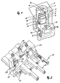
- Fig. 1 shows in perspective the area of a Whyabgriffimplantations, of which there are several in a branch connection connector according to the invention. Shown is the insulating housing 2 with the housing cylinder bore 3, which has a projecting, single thread 4, preferably consisting of two opposing sections, each with a circumferential extent of 120 ° (not shown in detail).
- a cylinder cap 5 is used according to the teachings of the invention and turned on the thread 4 of the cylinder bore.
- the thread is tolerated on the side of the cylinder cap as a thread furrow 6 at the bottom of the cylinder wall of the cylinder cap.
- the cylinder cap engages over the rotary abutment 7 of the Needlesabgriffiatas, which consists in the illustrated embodiment of the plastic body 8 with the rotary thrust bearing 7 and a lower side, made of a flat piece of metal fork-shaped insulation displacement contact 9.
- the insulation displacement contact 9 is rotationally fixed in a lower-side plug-in receptacle of the plastic body 8 and locked in place against pressure and pressure, by means of the latching device 10.
- the cylinder wall of the cylinder cap can spring up a bit, which is made possible, on the one hand, by the material weakening in the lower edge region (see tapped thread groove 6) and, on the other hand, by cavities 11 and 12 in the upper cap region.
- the cavity 12 is at the same time the plug-in receptacle for a screwdriver blade by means of which the cylinder cap 5 is rotatable.
- the plastic body 8 of the contact tapping element is guided rotationally fixed by means of the molded rotational stop 15 in the bottom 16 of the insulating material.
- the Kunststoffabgriffelement is linear and (in the illustration 1) downwardly against an electrical line, which is located below the bottom 16 and is fixed in position there in the insulating housing of the branch connector.
- the positionally accurate guidance of the insulation displacement contact 9 is improved in that the forked mouth of the insulation displacement contact pin engages over a guide web 17, which is accurately formed with the injection molding of the insulating material in the insulating material.
- the respective upright busbars 23 each terminate in a socket contact 25 which is disposed within an insulating material plug 26 of the branch connection connector.
- the sliding of the insulation displacement contacts on the respective edgewise busbars takes place in the illustrated embodiment by means of a linearly movable in the direction of displacement insulating sliding sleeve 27 having a pull tab 28 so that even with such a simple insulating sliding sleeve pushing and pulling off the respective insulation displacement contacts on or from the line to be contacted is possible.
Landscapes
- Connector Housings Or Holding Contact Members (AREA)
- Coupling Device And Connection With Printed Circuit (AREA)
- Details Of Connecting Devices For Male And Female Coupling (AREA)
- Cable Accessories (AREA)
- Manufacturing Of Electrical Connectors (AREA)
Abstract
Description
- Die Erfindung betrifft einen Abzweig-Anschlußverbinder zum abisolierfreien elektrischen Kontaktieren der Leitungsadern von elektrischen Leitungen, die eine Isolierung und/oder Abschirmung aufweisen und deren jeweilige Abgriffszonen parallel zueinander in einem Isolierstoffgehäuse lagefixiert gehalten sind, wobei der Kontaktabgriff pro Leitung jeweils mittels eines in dem Isolierstoffgehäuse rechtwinklig zur Leitung verschiebbar geführten Kontaktabgriffelementes erfolgt, das die Isolierung und/oder Abschirmung der Leitung durchtrennt und die Leitungsader kontaktiert.
- Solche Abzweig-Anschlußverbinder sind zum elektrischen Kontaktieren von Stromversorgungsleitungen (Phasenleiter, Nullleiter, Schutzleiter) bekannt, wie auch zum Abzweig-Kontaktieren von Datenleitungen, Steuerleiterungen etc. Die Leitungen können als parallele Einzelleitungen oder in Form eines Flachbandkabels mit einem definierten Rasterabstand vorliegen. Immer gilt, daß sie im Bereich ihrer für die Abzweigung benutzten Abgriffszonen parallel zueinander in dem Isolierstoffgehäuse des Abzweig-Anschlußverbinders lagefixiert gehalten sind.
- Als Kontaktabgriffelemente für solche Abzweig-Anschlußverbinder sind diverse Ausführungsformen bekannt. In der Praxis haben sich gabelförmige Schneid-Klemmkontakte durchgesetzt (siehe US-PS 5 059 137). Daneben gibt es nadelförmige Piercing-Kontakte oder sonstige, mit einer Kontaktspitze versehene Abgriffelemente, wie z.B. Dorne, die entweder ohne Drehung in die zu kontaktierenden Leitungen eingestochen werden oder die mittels eines mehrgängigen Gewindes in die zu kontaktierenden Leitungen hineingedreht werden (siehe hierzu die beschriebenen Ausführungsformen in DE 101 33 659 A1).
- Das Kontaktieren von Leitungsadern mit Hilfe einer spitzköpfigen Kontaktschraube, deren Spitze zum Durchstechen der Isolierung und/oder der Abschirmung einer Leitung geeignet ist, ist ebenfalls bekannt (siehe DE-AS 22 06 786 und DE 44 02 837 C2).
- Alle diese Ausführungsformen von Kontaktabgriffelementen sind entwickelt worden, um eine einfache und schnelle Installierbarkeit der gattungsgemäßen Abzweig-Anschlußverbinder zu ermöglichen. Dabei ist der Vorteil der Schnelligkeit insbesondere bei solchen Konstruktionen gegeben, bei denen mehrere, den verschiedenen Leitungsadern zugeordnete Kontaktabgriffelemente gemeinsam auf einer Druckplatte fest angeordnet sind und ohne Drehung in einem Arbeitsgang gleichzeitig in alle zu kontaktierenden Leitungen eingedrückt werden. Jedoch sind die dafür aufzuwendenden Kräfte im Regelfall sehr groß und von einem Elektromonteur ohne Hilfswerkzeuge nicht zu leisten. Deshalb bevorzugt der Elektromonteur in der Praxis Abzweig-Anschlußverbinder, die eine Kontaktierung der jeweiligen Leitungen mittels jeweils einer einzeln einschraubbaren Kontaktschraube ermöglichen. Das erfordert zwar zum Kontaktieren aller Leitungen eine Vielzahl von dreh-intensiven Schraubenbetätigungen, hat aber den Vorteil, in manueller Hinsicht für den Elektromonteur kraftschonend zu sein. Nachteilig ist jedoch, daß eine derartige Einschraub-Technik nur für nadelförmige Piercing-Kontakte oder für sonstige nadelförmige Durchstech-Kontakte verwendbar ist.
- Die Aufgabe der vorliegenden Erfindung besteht darin, einen Abzweig-Anschlußverbinder der gattungsgemäßen Art zu entwickeln, der universell für alle Arten von Kontaktabgriffelementen verwendbar ist und der zugleich von den Elektromonteuren schnell und einfach zu installieren ist.
- Diese Aufgabe wird erfindungsgemäß dadurch gelöst, daß der Kopf des Kontaktabgriffelementes ein kreisrundes Rotations-Gegenlager für einen im Isolierstoffgehäuse mit einem Bewegungsgewinde rotierbar gelagerten Vorschub-Rotationszylinder aufweist und daß das Kontaktabgriffelement in dem Isolierstoffgehäuse rotationsfest gelagert ist, jedoch sein Rotations-Gegenlager mit dem Vorschub-Rotationszylinder rotationsfähig verbunden ist derart, daß zwischen dem Vorschub-Rotationszylinder und dem Rotations-Gegenlager eine in Verschieberichtung des Kontaktabgriffelementes zug- und druckfeste Verbindung besteht.
- Die Lehre der Erfindung ermöglicht zwei wesentliche Vorteile zugleich. Die erfindungsgemäße Entkopplung des Verschiebe-Antriebs des Kontaktgriffelementes von dem Kontaktabgriffelement selbst hat zur Folge, daß nunmehr der Verschiebeantrieb in Form des vorgeschlagenen Vorschub-Rotationszylinders wesentlich besser als bisher auf die manuelle Handhabung durch den Elektromonteur ausgelegt werden kann und daß zugleich das Kontaktabgriffelement grundsätzlich rotationsfest und dennoch linear verschiebbar in dem Isolierstoffgehäuse geführt werden kann, so daß das Kontaktabgriffelement mit allen Arten der bis dato bekannt gewordenen Kontakten für den Leitungsabgriff bestückt sein kann, und zwar auch mit solchen, die ohne Drehung gegen die jeweils zu kontaktierende Leitung voranbewegt werden und die erforderlichenfalls auch wieder von der kontaktierten Leitung abgezogen werden müssen.
- Eine besonders vorteilhafte Ausführungsform der Erfindung ist nach Anspruch 2 dadurch gekennzeichnet, daß der Vorschub-Rotationszylinder in Form einer stirnseitig offenen Zylinderkappe ausgebildet ist, die das Rotations-Gegenlager des Kontaktabgriffelementes übergreift, wobei die Zylinderwand der Zylinderkappe auffedert und mit einem nach innen vorstehenden Rand in eine Ringnut des Rotations-Gegenlagers eingreift, und daß sodann das Bewegungsgewinde zwischen der Zylinderkappe und dem Isolierstoffgehäuse in Eingriff gebracht ist, wodurch die Zylinderwand der Zylinderkappe gegen eine erneute Auffederung gesperrt ist.
- Die neue Zylinderkappe, die das Kontaktabgriffelement übergreift, ermöglicht eine kurze axiale Bauweise der aus Zylinderkappe und Kontaktabgriffelement bestehenden Baugruppe. Die gewünschte Auffederungssperre der Zylinderkappe ist im Prinzip schon dann erreicht, wenn die vormontierte Baugruppe eine stückweit in die Zylinderbohrung eingesteckt ist, die für jedes Kontaktabgriffelement in dem Isolierstoffgehäuse des Abzweig-Anschlußverbinders vorhanden ist. Die endgültige Auffederungssperre ist dann gewährleistet, wenn die Zylinderkappe mit ihrem Außengewinde in das Innengewinde der Zylinderbohrung in dem Isolierstoffgehäuse paßgenau eingeschraubt ist. Die Zylinderkappe mit dem Kontaktabgriffelement befindet sich dann in der Gebrauchsstellung.
- Es ist zweckmäßig, die Zylinderbohrung mit einem Links-Drehanschlag zu versehen, den die Zylinderkappe am Anfang ihres Einschraubvorgangs in die Zylinderbohrung "überschnappend" überfährt und der verhindert, daß die Zylinderkappe unbeabsichtigt durch Linksdrehung wieder aus der Zylinderbohrung herausgedreht werden kann.
- Eine Zylinderkappe der erfindungsgemäßen Art ist in der paßgenauen Gehäuse-Zylinderbohrung äußerst stabil geführt und kann vom Elektromonteur robust gehandhabt werden. Ihr Kappenkopf kann eingeformte Steckaufnahmen für eine Schraubendreherklinge oder für ein sonstiges Werkzeug aufweisen.
- Das Bewegungsgewinde zwischen der Zylinderkappe und der Gehäuse-Zylinderbohrung ist nach Anspruch 4 bevorzugt eingängig ausgeführt, wodurch besondere Vorteile bezüglich der manuellen Handhabung des Zylinderkappen-Drehvorschubs und bezüglich der Fertigung (= Entformbarkeit der in Kunststoff-Spritzgießtechnik hergestellten Gehäuse-Zylinderbohrungen) dann erreicht werden, wenn der Gewindegang auf seiten der Zylinderkappe als Gewindefurche ausgebildet ist, die in die Zylinderwand der Zylinderkappe eingemuldet ist, wohingegen der Gewindegang auf seiten der Gehäuse-Zylinderbohrung vorspringend ausgebildet ist und aus zwei einander gegenüberliegenden Teilstücken besteht, die jeweils eine Umfangserstreckung kleiner als 180° haben, vorzugsweise etwa 120°.
- Im Ergebnis kann die Zylinderkappe der erfindungsgemäßen Art mit einem 120°-Drehvorschub schnell und einfach vom Elektromonteur gehandhabt werden, und sie liefert dennoch bei einer entsprechenden Steigung der Gewinde-Teilstücke einen ausreichend großen linearen Vorschub für das Kontaktabgriffelement, das linear und rotationsfest in der jeweiligen Gehäuse-Zylinderbohrung des Isolierstoffgehäuses des Abzweig-Anschlußverbinders geführt ist.
- Das Kontaktabgriffelement ist gemäß Anspruch 5 als Kunststoff-Spritzgießteil herstellbar und besteht aus einem Kunststoffkörper, der eine unterseitige Steckaufnahme besitzt, in die ein aus Metall gefertigter Kontakt zum elektrischen Kontaktieren der Leitungsader drehfest sowie zug- und druckfest verrastet ist. Die metallischen Kontakte können sowohl als nadelförmige Piercing-Kontakte als auch als gabelförmige Schneid-Klemmkontakte oder als Kontakt jeder anderen bekannten Bauart ausgebildet sein.
- Für Abzweig-Anschlußverbinder der gattungsgemäßen Art, deren Kontaktabgriffelemente mit einem aus einem Flachmaterial hergestellten gabelförmigen Schneid-Klemmkontakt bestückt sind, wird als weitere Erfindungsidee vorgeschlagen, daß der gabelförmige Schneid-Klemmkontakt bei seiner Verschiebebewegung mittels eines Führungssteges geführt ist, der aus dem Material des Isolierstoffgehäuses ausgeformt ist und der in dem Isolierstoffgehäuse achsparallel und im wesentlichen mittensymmetrisch und oberhalb der zu kontaktierenden Leitungsader positioniert ist derart, daß das gabelförmige Maul des Schneid-Klemmkontaktes den Führungssteg übergreift und von dem Führungssteg geführt ist, bevor der Schneid-Klemmkontakt die Isolierung und/oder die Abschirmung der unter dem Führungssteg verlaufenden Leitung berührt.
- Der vorgeschlagene Führungssteg ist von erheblichem Vorteil, wenn ein- und derselbe Abzweig-Anschlußverbinder für die Kontaktierung von elektrischen Leitungen mit einer bestimmten größeren Bandbreite der Leiterquerschnitte verwendet werden soll (z.B. für Leiterquerschnitte von 2,5 mm2 bis 4,0 mm2). Dabei ist auch wichtig, daß bei einem Flachbandkabel die von Hersteller zu Hersteller variierenden Abstandstoleranzen der einzelnen Leitungen berücksichtigt werden. Das ist mit Hilfe der vorgeschlagenen Führungsstege möglich, die spritzgieß-technisch sehr genau in dem Isolierstoffgehäuse des Abzweig-Anschlußverbinders herstellbar sind und die eine entsprechend positionsgenaue Führung der jeweiligen Schneid-Klemmkontakte garantieren.
- Eine weitere Verbesserung ist bei einem erfindungsgemäßen Abzweig-Anschlußverbinder nach Anspruch 9 dann erreicht, wenn der gabelförmige Schneid-Klemmkontakt bei seiner Verschiebebewegung mittels einer Hochkant-Stromschiene geführt ist, die aus einem metallischen Flachmaterial gefertigt ist, das sich in einer Erstreckungsebene parallel zur Verschiebebewegung des Schneid-Klemmkontaktes erstreckt, wobei die Hochkant-Stromschiene in dem Isolierstoffgehäuse ortsfest gehalten ist und von einer nach unten, in Verschieberichtung des Schneid-Klemmkontaktes U-förmig offenen Blattfederklemme übergriffen wird, die mit dem Schneid-Klemmkontakt elektrisch und mechanisch verbunden ist und die als Gleitschiebekontakt beim Verschieben des Schneid-Klemmkontaktes auf der Hochkant-Stromschiene mitläuft.
- Werden bei einem Abzweig-Anschlußverbinder die zuletzt benannten Hochkant-Stromschienen mit den davor benannten Führungsstegen kombiniert in der Weise, daß sich die Erstreckungsebene der jeweiligen Hochkant-Stromschiene und die Führungsstegebene, die durch die Achse des jeweiligen Führungssteges und die Achse der zu kontaktierenden Leitungsader definiert ist, rechtwinklig kreuzen, dann entsteht in der Kreuzungslinie der unter 90° aufeinandertreffenden Ebenen eine spurgenaue Kreuz-Führung für das jeweilige Kontaktabgriffelement.
- Nachfolgend werden Ausführungsbeispiele der Erfindung anhand der Zeichnungen beschrieben. Es zeigen:
- Fig. 1
- in perspektivischer Darstellung ein erstes Ausführungsbeispiel,
- Fig. 2
- in perspektivischer Darstellung ein zweites Ausführungsbeispiel.
- Fig. 1 zeigt in perspektivischer Darstellung den Bereich eines Kontaktabgriffelementes, von denen es mehrere bei einem erfindungsgemäßen Abzweig-Anschlußverbinder gibt. Dargestellt ist das Isolierstoffgehäuse 2 mit der der Gehäuse-Zylinderbohrung 3, die einen vorspringenden, eingängigen Gewindegang 4 aufweist, vorzugsweise bestehend aus zwei einander gegenüberliegenden Teilstücken mit jeweils einer Umfangserstreckung von 120° (im einzelnen nicht dargestellt).
- In die Gehäuse-Zylinderbohrung ist nach der Lehre der Erfindung eine Zylinderkappe 5 eingesetzt und auf den Gewindegang 4 der Zylinderbohrung aufgedreht. Zu diesem Zweck ist der Gewindegang auf seiten der Zylinderkappe als Gewindefurche 6 am unteren Rand der Zylinderwand der Zylinderkappe eingemuldet.
- Die Zylinderkappe übergreift das Rotations-Gegenlager 7 des Kontaktabgriffelementes, das bei dem dargestellten Ausführungsbeispiel aus dem Kunststoffkörper 8 mit dem Rotations-Gegenlager 7 und einem unterseitigen, aus einem flachen Metallstück gefertigten gabelförmigen Schneid-Klemmkontakt 9 besteht. Der Schneid-Klemmkontakt 9 ist in einer unterseitigen Steckaufnahme des Kunststoffkörpers 8 drehfest sowie zug- und druckfest eingerastet, und zwar mittels der Rastvorrichtung 10.
- Beim Vormontieren der Zylinderkappe 5 und des Kontaktabgriffelementes 7, 8, 9 greift der nach innen vorstehende Rand 13 der Zylinderkappe in die Ringnut 14 des Kontaktabgriffelementes ein. Zu diesem Zweck kann die Zylinderwand der Zylinderkappe etwas auffedern, was zum einen durch die Materialschwächung im unteren Randbereich (siehe eingemuldete Gewindefurche 6) und zum anderen durch Hohlräume 11 und 12 im oberen Kappenbereich ermöglicht wird. Der Hohlraum 12 ist zugleich die Steckaufnahme für eine Schraubendreherklinge mittels der die Zylinderkappe 5 rotierbar ist.
- Der Kunststoffkörper 8 des Kontaktabgriffelementes ist mittels des angespritzten Drehstopps 15 in dem Boden 16 des Isolierstoffgehäuses rotationsfest geführt. Durch eine Drehung bzw. Rotation der Zylinderkappe wird das Kontaktabgriffelement linear und (in der Darstellung der Fig. 1) nach unten gegen eine elektrische Leitung vorgeschoben, die sich unterhalb des Bodens 16 befindet und dort im Isolierstoffgehäuse des Abzweig-Anschlußverbinders lagefixiert gehalten ist.
- Infolge der zug- und druckfesten Einrastung des Innenrandes 13 der Zylinderkappe in die Ringnut 14 des Kontaktabgriffelementes ist es für den Elektromonteur problemlos möglich, den Schneid-Klemmkontakt 9 auf eine zu kontaktierende Leitung aufzuschieben und den Schneid-Klemmkontakt auch wieder von dieser Leitung abzuziehen.
- Die positionsgenaue Führung des Schneid-Klemmkontaktes 9 ist dadurch verbessert, daß das gabelförmige Maul des Schneid-Klemmkontaktes einen Führungssteg 17 übergreift, der beim Spritzvorgang des Isolierstoffgehäuses in dem Isolierstoffgehäuse positionsgenau mit ausgeformt ist.
- Fig. 2 zeigt ein Ausführungsbeispiel der Erfindung gemäß den Ansprüche 8 und 9.
- Die Verschiebung des gabelförmigen Schneid-Klemmkontaktes 20 gegen die im unteren Teil des Isolierstoffgehäuses lagefixiert gehaltenen Leitung 21 ist mittels des Führungssteges 22 im oberen Teil des Isolierstoffgehäuses geführt. Diese Führung ist zu einer spurgenauen Kreuz-Führung dadurch ausgebaut, daß zusätzlich eine Hochkant-Stromschiene 23 im Isolierstoffgehäuse ortsfest montiert ist, die in Verschieberichtung von einer (in der Darstellung der Fig. 2) nach unten offenen U-förmigen Blattfeder 24 übergriffen wird, die mit dem Schneid-Klemmkontakt 20 elektrisch und mechanisch fest verbunden ist und die als Gleitschiebekontakt beim Verschieben des Schneid-Klemmkontaktes auf der Hochkant-Stromschiene mitläuft (vergleiche hierzu die jeweiligen Verschiebepositionen bei den benachbart dargestellten Kontaktabgriffelementen).
- Die jeweiligen Hochkant-Stromschienen 23 enden jeweils in einem Buchsenkontakt 25, der innerhalb eines Isolierstoff-Steckers 26 des Abzweig-Anschlußverbinders angeordnet ist. Das Aufschieben der Schneid-Klemmkontakte auf die jeweiligen Hochkant-Stromschienen erfolgt bei dem dargestellten Ausführungsbeispiel mittels einer linear in Verschieberichtung zu bewegenden Isolierstoff-Schiebehülse 27, die eine Zuglasche 28 aufweist, so daß auch mit einer so einfachen Isolierstoff-Schiebehülse das Aufschieben und das Abziehen der jeweiligen Schneid-Klemmkontakte auf bzw. von der zu kontaktierenden Leitung möglich ist.
Claims (11)
- Abzweig-Anschlußverbinder- zum abisolierfreien elektrischen Kontaktieren der Leitungsadern von elektrischen Leitungen, die eine Isolierung und/oder Abschirmung aufweisen und deren jeweilige Abgriffszonen parallel zueinander in einem Isolierstoffgehäuse lagefixiert gehalten sind,- wobei der Kontaktabgriff pro Leitung jeweils mittels eines in dem Isolierstoffgehäuse rechtwinklig zur Leitung verschiebbar geführten Kontaktabgriffelementes erfolgt, das die Isolierung und/oder Abschirmung der Leitung durchtrennt und die Leitungsader kontaktiert,
dadurch gekennzeichnet,- daß der Kopf des Kontaktabgriffelementes ein kreisrundes Rotations-Gegenlager (7) für einen im Isolierstoffgehäuse mit einem Bewegungsgewinde (4, 6) rotierbar gelagerten Vorschub-Rotationszylinder (5) aufweist,- und daß das Kontaktabgriffelement in dem Isolierstoffgehäuse rotationsfest gelagert ist, jedoch sein Rotations-Gegenlager mit dem Vorschub-Rotationszylinder rotationsfähig verbunden ist derart, daß zwischen dem Vorschub-Rotationszylinder und dem Rotations-Gegenlager eine in Verschieberichtung des Kontaktabgriffelementes zug- und druckfeste Verbindung besteht. - Abzweig-Anschlußverbinder nach Anspruch 1,
dadurch gekennzeichnet,- daß der Vorschub-Rotationszylinder in Form einer stirnseitig offenen Zylinderkappe (5) ausgebildet ist, die das Rotations-Gegenlager (7) des Kontaktabgriffelementes übergreift,- wobei die Zylinderwand der Zylinderkappe auffedert und mit einem nach innen vorstehenden Rand (13) in eine Ringnut (14) des Rotations-Gegenlagers eingreift,- und daß sodann das Bewegungsgewinde (4, 6) zwischen der Zylinderkappe und dem Isolierstoffgehäuse in Eingriff gebracht ist, wodurch die Zylinderwand der Zylinderkappe gegen eine erneute Auffederung gesperrt ist. - Abzweig-Anschlußverbinder nach Anspruch 2,
dadurch gekennzeichnet,- daß die Zylinderkappe aus Kunststoff gefertigt ist- und daß die Zylinderkappe im oberen Bereich Materialschwächungen aufweist (z.B. in Form von Hohlräumen und/oder Wanddurchbrüchen), die das Auffedern der Zylinderwand der Zylinderkappe beim Übergreifen des Rotations-Gegenlagers begünstigen. - Abzweig-Anschlußverbinder nach einem der Ansprüche 1 bis 3,
dadurch gekennzeichnet,- daß das Bewegungsgewinde eingängig ausgeführt ist- und daß der Gewindegang auf seiten der Zylinderkappe als Gewindefurche (6) ausgebildet ist, die in die Zylinderwand der Zylinderkappe eingemuldet ist,- wohingegen der Gewindegang (4) auf seiten des Isolierstoff gehäuses vorspringend ausgebildet ist und aus zwei einander gegenüberliegenden Teilstücken besteht, die jeweils eine Umfangserstreckung kleiner als 180° haben, vorzugsweise etwa 120°. - Abzweig-Anschlußverbinder nach einem der Ansprüche 1 bis 4,
dadurch gekennzeichnet,- daß das Kontaktabgriffelementes aus einem Kunststoffkörper (8) besteht, der eine unterseitige Steckaufnahme besitzt, in die ein aus Metall gefertigter Kontakt zum elektrischen Kontaktieren der Leitungsader drehfest sowie zug- und druckfest verrastet ist. - Abzweig-Anschlußverbinder nach Anspruch 5,
dadurch gekennzeichnet,- daß der Kontakt ein nadelförmiger Piercing-Kontakt ist. - Abzweig-Anschlußverbinder nach Anspruch 5,
dadurch gekennzeichnet,- daß der Kontakt ein gabelförmiger Schneid- Klemmkontakt (9) ist. - Abzweig-Anschlußverbinder- zum abisolierfreien elektrischen Kontaktieren der Leitungsadern von elektrischen Leitungen, die eine Isolierung und/oder Abschirmung aufweisen und deren jeweilige Abgriffszonen parallel zueinander in einem Isolierstoffgehäuse lagefixiert gehalten sind,- wobei der Kontaktabgriff pro Leitung jeweils mittels eines in dem Isolierstoffgehäuse rechtwinklig zur Leitung verschiebbar geführten Kontaktabgriffelementes erfolgt, das in Form eines aus einem Flachmaterial hergestellten gabelförmigen Schneid-Klemmkontaktes ausgebildet ist,
dadurch gekennzeichnet,- daß der gabelförmige Schneid-Klemmkontakt (9, 20) bei seiner Verschiebebewegung mittels eines Führungssteges (17, 22) geführt ist, der aus dem Material des Isolierstoffgehäuses ausgeformt ist und der in dem Isolierstoffgehäuse achsparallel und im wesentlichen mittensymmetrisch und oberhalb der zu kontaktierenden Leitungsader (21) positioniert ist- derart, daß das gabelförmige Maul des Schneid-Klemmkontaktes den Führungssteg übergreift und von dem Führungssteg geführt ist, bevor der Schneid-Klemmkontakt die Isolierung und/oder die Abschirmung der unter dem Führungssteg verlaufenden Leitung berührt. - Abzweig-Anschlußverbinder- zum abisolierfreien elektrischen Kontaktieren der Leitungsadern von elektrischen Leitungen, die eine Isolierung und/oder Abschirmung aufweisen und deren jeweilige Abgriffszonen parallel zueinander in einem Isolierstoffgehäuse lagefixiert gehalten sind,- wobei der Kontaktabgriff pro Leitung jeweils mittels eines in dem Isolierstoffgehäuse rechtwinklig zur Leitung verschiebbar geführten Kontaktabgriffelementes erfolgt, das in Form eines aus einem Flachmaterial hergestellten gabelförmigen Schneid-Klemmkontaktes ausgebildet ist,
dadurch gekennzeichnet,- daß der gabelförmige Schneid-Klemmkontakt (20) bei seiner Verschiebebewegung mittels einer Hochkant-Stromschiene (23) geführt ist, die aus einem metallischen Flachmaterial gefertigt ist, das sich in einer Erstreckungsebene parallel zur Verschiebebewegung des Schneid-Klemmkontaktes erstreckt,- wobei die Hochkant-Stromschiene in dem Isolierstoffgehäuse ortsfest gehalten ist und von einer nach unten, in Verschieberichtung des Schneid-Klemmkontaktes U-förmig offenen Blattfederklemme (24) übergriffen wird, die mit dem Schneid-Klemmkontakt elektrisch und mechanisch verbunden ist und die als Gleitschiebekontakt beim Verschieben des Schneid-Klemmkontaktes auf der Hochkant-Stromschiene mitläuft. - Abzweig-Anschlußverbinder nach Anspruch 8 in Kombination mit Anspruch 9,
dadurch gekennzeichnet,- daß sich die Erstreckungsebene der Hochkant-Stromschiene (23) und die Führungsstegebene, die durch die Achse des Führungssteges (22) und die Achse der zu kontaktierenden Leitungsader (21) definiert ist, rechtwinklig kreuzen. - Abzweig-Anschlußverbinder nach einem der Ansprüche 8, 9 oder 10,
dadurch gekennzeichnet,- daß der Abzweig-Anschlußverbinder Konstruktionsmerkmale der Ansprüche 1 bis 7 aufweist.
Applications Claiming Priority (1)
| Application Number | Priority Date | Filing Date | Title |
|---|---|---|---|
| DE102004037997A DE102004037997A1 (de) | 2004-08-04 | 2004-08-04 | Elektrischer Abzweig-Anschlußverbinder |
Publications (3)
| Publication Number | Publication Date |
|---|---|
| EP1624528A2 true EP1624528A2 (de) | 2006-02-08 |
| EP1624528A3 EP1624528A3 (de) | 2006-03-29 |
| EP1624528B1 EP1624528B1 (de) | 2010-05-05 |
Family
ID=35427404
Family Applications (1)
| Application Number | Title | Priority Date | Filing Date |
|---|---|---|---|
| EP05015827A Expired - Lifetime EP1624528B1 (de) | 2004-08-04 | 2005-07-21 | Elektrischer Abzweig-Anschlussverbinder |
Country Status (4)
| Country | Link |
|---|---|
| US (1) | US20060035512A1 (de) |
| EP (1) | EP1624528B1 (de) |
| AT (1) | ATE467249T1 (de) |
| DE (2) | DE102004037997A1 (de) |
Cited By (2)
| Publication number | Priority date | Publication date | Assignee | Title |
|---|---|---|---|---|
| EP2945224A1 (de) | 2014-05-13 | 2015-11-18 | Wieland Electric GmbH | Flachbandabgriff |
| CN107508221A (zh) * | 2017-08-15 | 2017-12-22 | 华中科技大学 | 一种模块化的高压分线器 |
Families Citing this family (3)
| Publication number | Priority date | Publication date | Assignee | Title |
|---|---|---|---|---|
| DE102007029047A1 (de) * | 2007-06-21 | 2008-12-24 | Phoenix Contact Gmbh & Co. Kg | Anschlußvorrichtung für ein Flachkabel und Betätigungswerkzeug zur Verwendung bei einer Anschlußvorrichtung |
| US11133627B2 (en) * | 2018-11-09 | 2021-09-28 | Herman Miller, Inc. | Power distribution system |
| AU2021292753B2 (en) | 2020-06-18 | 2023-12-21 | Ideal Industries, Inc. | Conductor terminal |
Citations (4)
| Publication number | Priority date | Publication date | Assignee | Title |
|---|---|---|---|---|
| DE2206786A1 (de) | 1972-02-12 | 1973-08-16 | Form Ges Formgebung | Stapelbarer selbsttragender kanister |
| US5059137A (en) | 1990-08-23 | 1991-10-22 | Amp Incorporated | Insulation displacement contact for flat cable |
| DE4402837C2 (de) | 1994-01-31 | 1998-08-06 | Daetwyler Ag | Elektrisches Installationssystem, gebildet durch Flachkabel und Anschlußvorrichtung |
| DE10133659A1 (de) | 2001-07-11 | 2003-01-30 | Daetwyler Ag | Anschlußvorrichtung zum Anzapfen eines Flachkabels |
Family Cites Families (17)
| Publication number | Priority date | Publication date | Assignee | Title |
|---|---|---|---|---|
| NL175121C (nl) * | 1975-05-15 | 1984-09-17 | Du Pont | Elektrische verbindingsinrichting. |
| US4232927A (en) * | 1979-03-16 | 1980-11-11 | E. I. Du Pont De Nemours And Company | Electrical connector |
| AR246820A1 (es) * | 1987-07-07 | 1994-09-30 | Raychem Corp | Un dispositivo para conectar un cable aislado a un borne. |
| DE3933942A1 (de) * | 1989-10-11 | 1991-04-18 | Pfaff Ag G M | Einrichtung zum elektrischen verbinden von mindestens einem verbraucher und einem mehradrigen kabel |
| EP0519196B1 (de) * | 1991-06-14 | 1995-09-13 | Molex Incorporated | Klemmleiste für gedruckte Leiterplatten |
| US5139440A (en) * | 1991-06-26 | 1992-08-18 | Reliance Comm/Tec Corporation | Environmentally sealed insulation displacement connector terminal block |
| US5364288A (en) * | 1992-07-24 | 1994-11-15 | North American Philips Corporation | Electrical connecting device |
| DK115493D0 (da) * | 1993-10-15 | 1993-10-15 | Lk As | Aftastningssystem |
| US5451167A (en) * | 1994-07-28 | 1995-09-19 | Illinois Tool Works Inc. | Grounding clip |
| DE19504013C1 (de) * | 1995-02-07 | 1996-07-18 | Lumberg Karl Gmbh & Co | Anschlußvorrichtung zur wahlfreien Herstellung eines wiederverwendbaren elektrischen Anschlusses bzw. Abgriffs an mehradrigen elektrischen Leitungen |
| DE29605984U1 (de) * | 1996-03-30 | 1996-07-04 | Festo Kg, 73734 Esslingen | Anschlußeinrichtung für Flachbandkabel |
| US6328592B1 (en) * | 1996-06-07 | 2001-12-11 | Molex Incorporated | Electrical connector with cable clamping means |
| DE19854200A1 (de) * | 1998-11-24 | 2000-06-15 | Siemens Ag | Vorrichtung zum Kontaktieren einer elektrischen Leitung, insbesondere einer Flachbandleitung |
| DE19903030C1 (de) * | 1999-01-26 | 2001-05-03 | Siemens Ag | Vorrichtung zur abisolierfreien Kontaktierung eines Flachkabels |
| WO2000055943A1 (de) * | 1999-03-12 | 2000-09-21 | Grote & Hartmann Gmbh & Co. Kg | Elektrischer steckverbinder mit mindestens einem schneidklemmkontaktelement aus einem blechstanzteil sowie korrespondierender gegensteckverbinder hierzu |
| DE19944312C1 (de) * | 1999-09-15 | 2001-04-05 | Siemens Ag | Vorrichtung zum Kontaktieren einer elektrischen Leitung, insbesondere einer Flachbandleitung |
| DE10039202B4 (de) * | 2000-08-10 | 2005-01-05 | Siemens Ag | Schneidklemmeinrichtung |
-
2004
- 2004-08-04 DE DE102004037997A patent/DE102004037997A1/de not_active Withdrawn
-
2005
- 2005-07-21 AT AT05015827T patent/ATE467249T1/de not_active IP Right Cessation
- 2005-07-21 EP EP05015827A patent/EP1624528B1/de not_active Expired - Lifetime
- 2005-07-21 DE DE502005009516T patent/DE502005009516D1/de not_active Expired - Lifetime
- 2005-08-03 US US11/196,558 patent/US20060035512A1/en not_active Abandoned
Patent Citations (4)
| Publication number | Priority date | Publication date | Assignee | Title |
|---|---|---|---|---|
| DE2206786A1 (de) | 1972-02-12 | 1973-08-16 | Form Ges Formgebung | Stapelbarer selbsttragender kanister |
| US5059137A (en) | 1990-08-23 | 1991-10-22 | Amp Incorporated | Insulation displacement contact for flat cable |
| DE4402837C2 (de) | 1994-01-31 | 1998-08-06 | Daetwyler Ag | Elektrisches Installationssystem, gebildet durch Flachkabel und Anschlußvorrichtung |
| DE10133659A1 (de) | 2001-07-11 | 2003-01-30 | Daetwyler Ag | Anschlußvorrichtung zum Anzapfen eines Flachkabels |
Cited By (4)
| Publication number | Priority date | Publication date | Assignee | Title |
|---|---|---|---|---|
| EP2945224A1 (de) | 2014-05-13 | 2015-11-18 | Wieland Electric GmbH | Flachbandabgriff |
| DE102014208970A1 (de) | 2014-05-13 | 2015-11-19 | Wieland Electric Gmbh | Flachbandabgriff |
| CN107508221A (zh) * | 2017-08-15 | 2017-12-22 | 华中科技大学 | 一种模块化的高压分线器 |
| CN107508221B (zh) * | 2017-08-15 | 2023-01-06 | 华中科技大学 | 一种模块化的高压分线器 |
Also Published As
| Publication number | Publication date |
|---|---|
| EP1624528B1 (de) | 2010-05-05 |
| EP1624528A3 (de) | 2006-03-29 |
| ATE467249T1 (de) | 2010-05-15 |
| US20060035512A1 (en) | 2006-02-16 |
| DE102004037997A1 (de) | 2006-03-16 |
| DE502005009516D1 (de) | 2010-06-17 |
Similar Documents
| Publication | Publication Date | Title |
|---|---|---|
| DE19835459C2 (de) | Anschlußklemme für elektrische Leiter | |
| EP2715872A1 (de) | Prüf- und anschlussvorrichtungsanordnung und prüfvorrichtung | |
| DE102016124172A1 (de) | Steckverbinder zur kraftlosen Kontaktierung auf einer Leiterkarte | |
| EP2577805A1 (de) | Kontaktelement für steckeranordnung | |
| EP3176879A1 (de) | Elektrische klemme | |
| DE2328505C2 (de) | Elektrischer Verbinder zur elektrischen Verbindung wenigstens zweier Leitungsdrähte | |
| EP1133813A1 (de) | Vorrichtung zum kontaktieren einer elektrischen leitung, insbesondere einer flachbandleitung | |
| EP0877445B1 (de) | Anschlussvorrichtung für Flachkabel | |
| EP1624528B1 (de) | Elektrischer Abzweig-Anschlussverbinder | |
| EP3076188A1 (de) | Test-contactor, verfahren und verwendung | |
| DE19903030C1 (de) | Vorrichtung zur abisolierfreien Kontaktierung eines Flachkabels | |
| DE4411731B4 (de) | Aufputz-Steckdose | |
| DE19604615C1 (de) | Kontaktierungseinrichtung | |
| EP1131859B1 (de) | Abzweigvorrichtung für kabel | |
| DE2107464C3 (de) | Elektrischer Wippenschalter | |
| DE2528487C2 (de) | Rastende Steckverbindung | |
| EP2363924A1 (de) | Vorrichtung zum Verbinden eines Kabels mit einem in einem Gehäuse angeordneten elektrischen Bauelement | |
| EP1355379B1 (de) | Steckverbinder mit Schneidklemmkontakten | |
| WO2017129179A1 (de) | Linearbewegliches gleitkontaktelement mit transportvorrichtung und verfahren zur herstellung | |
| DE2832574A1 (de) | Elektrische widerstands-punktschweissvorrichtung | |
| WO1995003615A1 (de) | Abzweigdosensystem für flachkabel | |
| DE102005005917A1 (de) | Anschlussklemme für einen isolierten elektrischen Leiter | |
| DE10329775B4 (de) | Kabelanschluß- oder -verbindungseinrichtung | |
| DE102008011217B4 (de) | Betätigungswerkzeug zum Anschließen eines isolierten Leiters | |
| EP0200912A2 (de) | Elektrisch steuerbares Türschloss mit Profilschliesszylinder |
Legal Events
| Date | Code | Title | Description |
|---|---|---|---|
| PUAI | Public reference made under article 153(3) epc to a published international application that has entered the european phase |
Free format text: ORIGINAL CODE: 0009012 |
|
| AK | Designated contracting states |
Kind code of ref document: A2 Designated state(s): AT BE BG CH CY CZ DE DK EE ES FI FR GB GR HU IE IS IT LI LT LU LV MC NL PL PT RO SE SI SK TR |
|
| AX | Request for extension of the european patent |
Extension state: AL BA HR MK YU |
|
| PUAL | Search report despatched |
Free format text: ORIGINAL CODE: 0009013 |
|
| AK | Designated contracting states |
Kind code of ref document: A3 Designated state(s): AT BE BG CH CY CZ DE DK EE ES FI FR GB GR HU IE IS IT LI LT LU LV MC NL PL PT RO SE SI SK TR |
|
| AX | Request for extension of the european patent |
Extension state: AL BA HR MK YU |
|
| 17P | Request for examination filed |
Effective date: 20060929 |
|
| 17Q | First examination report despatched |
Effective date: 20061026 |
|
| AKX | Designation fees paid |
Designated state(s): AT BE BG CH CY CZ DE DK EE ES FI FR GB GR HU IE IS IT LI LT LU LV MC NL PL PT RO SE SI SK TR |
|
| GRAP | Despatch of communication of intention to grant a patent |
Free format text: ORIGINAL CODE: EPIDOSNIGR1 |
|
| GRAS | Grant fee paid |
Free format text: ORIGINAL CODE: EPIDOSNIGR3 |
|
| GRAA | (expected) grant |
Free format text: ORIGINAL CODE: 0009210 |
|
| AK | Designated contracting states |
Kind code of ref document: B1 Designated state(s): AT BE BG CH CY CZ DE DK EE ES FI FR GB GR HU IE IS IT LI LT LU LV MC NL PL PT RO SE SI SK TR |
|
| REG | Reference to a national code |
Ref country code: GB Ref legal event code: FG4D Free format text: NOT ENGLISH |
|
| REG | Reference to a national code |
Ref country code: CH Ref legal event code: EP |
|
| REG | Reference to a national code |
Ref country code: IE Ref legal event code: FG4D Free format text: LANGUAGE OF EP DOCUMENT: GERMAN |
|
| REF | Corresponds to: |
Ref document number: 502005009516 Country of ref document: DE Date of ref document: 20100617 Kind code of ref document: P |
|
| REG | Reference to a national code |
Ref country code: CH Ref legal event code: NV Representative=s name: BOHEST AG |
|
| REG | Reference to a national code |
Ref country code: SE Ref legal event code: TRGR |
|
| REG | Reference to a national code |
Ref country code: NL Ref legal event code: VDEP Effective date: 20100505 |
|
| LTIE | Lt: invalidation of european patent or patent extension |
Effective date: 20100505 |
|
| PG25 | Lapsed in a contracting state [announced via postgrant information from national office to epo] |
Ref country code: NL Free format text: LAPSE BECAUSE OF FAILURE TO SUBMIT A TRANSLATION OF THE DESCRIPTION OR TO PAY THE FEE WITHIN THE PRESCRIBED TIME-LIMIT Effective date: 20100505 Ref country code: LT Free format text: LAPSE BECAUSE OF FAILURE TO SUBMIT A TRANSLATION OF THE DESCRIPTION OR TO PAY THE FEE WITHIN THE PRESCRIBED TIME-LIMIT Effective date: 20100505 Ref country code: ES Free format text: LAPSE BECAUSE OF FAILURE TO SUBMIT A TRANSLATION OF THE DESCRIPTION OR TO PAY THE FEE WITHIN THE PRESCRIBED TIME-LIMIT Effective date: 20100816 |
|
| PG25 | Lapsed in a contracting state [announced via postgrant information from national office to epo] |
Ref country code: FI Free format text: LAPSE BECAUSE OF FAILURE TO SUBMIT A TRANSLATION OF THE DESCRIPTION OR TO PAY THE FEE WITHIN THE PRESCRIBED TIME-LIMIT Effective date: 20100505 Ref country code: IS Free format text: LAPSE BECAUSE OF FAILURE TO SUBMIT A TRANSLATION OF THE DESCRIPTION OR TO PAY THE FEE WITHIN THE PRESCRIBED TIME-LIMIT Effective date: 20100905 Ref country code: LV Free format text: LAPSE BECAUSE OF FAILURE TO SUBMIT A TRANSLATION OF THE DESCRIPTION OR TO PAY THE FEE WITHIN THE PRESCRIBED TIME-LIMIT Effective date: 20100505 Ref country code: SI Free format text: LAPSE BECAUSE OF FAILURE TO SUBMIT A TRANSLATION OF THE DESCRIPTION OR TO PAY THE FEE WITHIN THE PRESCRIBED TIME-LIMIT Effective date: 20100505 |
|
| REG | Reference to a national code |
Ref country code: IE Ref legal event code: FD4D |
|
| PG25 | Lapsed in a contracting state [announced via postgrant information from national office to epo] |
Ref country code: GR Free format text: LAPSE BECAUSE OF FAILURE TO SUBMIT A TRANSLATION OF THE DESCRIPTION OR TO PAY THE FEE WITHIN THE PRESCRIBED TIME-LIMIT Effective date: 20100806 Ref country code: CY Free format text: LAPSE BECAUSE OF FAILURE TO SUBMIT A TRANSLATION OF THE DESCRIPTION OR TO PAY THE FEE WITHIN THE PRESCRIBED TIME-LIMIT Effective date: 20100505 Ref country code: PL Free format text: LAPSE BECAUSE OF FAILURE TO SUBMIT A TRANSLATION OF THE DESCRIPTION OR TO PAY THE FEE WITHIN THE PRESCRIBED TIME-LIMIT Effective date: 20100505 |
|
| BERE | Be: lapsed |
Owner name: WAGO VERWALTUNGSGESELLSCHAFT MBH Effective date: 20100731 |
|
| PG25 | Lapsed in a contracting state [announced via postgrant information from national office to epo] |
Ref country code: EE Free format text: LAPSE BECAUSE OF FAILURE TO SUBMIT A TRANSLATION OF THE DESCRIPTION OR TO PAY THE FEE WITHIN THE PRESCRIBED TIME-LIMIT Effective date: 20100505 Ref country code: IE Free format text: LAPSE BECAUSE OF FAILURE TO SUBMIT A TRANSLATION OF THE DESCRIPTION OR TO PAY THE FEE WITHIN THE PRESCRIBED TIME-LIMIT Effective date: 20100505 Ref country code: PT Free format text: LAPSE BECAUSE OF FAILURE TO SUBMIT A TRANSLATION OF THE DESCRIPTION OR TO PAY THE FEE WITHIN THE PRESCRIBED TIME-LIMIT Effective date: 20100906 Ref country code: DK Free format text: LAPSE BECAUSE OF FAILURE TO SUBMIT A TRANSLATION OF THE DESCRIPTION OR TO PAY THE FEE WITHIN THE PRESCRIBED TIME-LIMIT Effective date: 20100505 |
|
| PG25 | Lapsed in a contracting state [announced via postgrant information from national office to epo] |
Ref country code: CZ Free format text: LAPSE BECAUSE OF FAILURE TO SUBMIT A TRANSLATION OF THE DESCRIPTION OR TO PAY THE FEE WITHIN THE PRESCRIBED TIME-LIMIT Effective date: 20100505 Ref country code: SK Free format text: LAPSE BECAUSE OF FAILURE TO SUBMIT A TRANSLATION OF THE DESCRIPTION OR TO PAY THE FEE WITHIN THE PRESCRIBED TIME-LIMIT Effective date: 20100505 Ref country code: RO Free format text: LAPSE BECAUSE OF FAILURE TO SUBMIT A TRANSLATION OF THE DESCRIPTION OR TO PAY THE FEE WITHIN THE PRESCRIBED TIME-LIMIT Effective date: 20100505 Ref country code: MC Free format text: LAPSE BECAUSE OF NON-PAYMENT OF DUE FEES Effective date: 20100731 |
|
| PLBE | No opposition filed within time limit |
Free format text: ORIGINAL CODE: 0009261 |
|
| STAA | Information on the status of an ep patent application or granted ep patent |
Free format text: STATUS: NO OPPOSITION FILED WITHIN TIME LIMIT |
|
| PG25 | Lapsed in a contracting state [announced via postgrant information from national office to epo] |
Ref country code: IT Free format text: LAPSE BECAUSE OF FAILURE TO SUBMIT A TRANSLATION OF THE DESCRIPTION OR TO PAY THE FEE WITHIN THE PRESCRIBED TIME-LIMIT Effective date: 20100505 |
|
| 26N | No opposition filed |
Effective date: 20110208 |
|
| REG | Reference to a national code |
Ref country code: DE Ref legal event code: R097 Ref document number: 502005009516 Country of ref document: DE Effective date: 20110207 |
|
| PG25 | Lapsed in a contracting state [announced via postgrant information from national office to epo] |
Ref country code: BE Free format text: LAPSE BECAUSE OF NON-PAYMENT OF DUE FEES Effective date: 20100731 |
|
| PGFP | Annual fee paid to national office [announced via postgrant information from national office to epo] |
Ref country code: FR Payment date: 20110729 Year of fee payment: 7 |
|
| PG25 | Lapsed in a contracting state [announced via postgrant information from national office to epo] |
Ref country code: AT Free format text: LAPSE BECAUSE OF NON-PAYMENT OF DUE FEES Effective date: 20100721 |
|
| PGFP | Annual fee paid to national office [announced via postgrant information from national office to epo] |
Ref country code: SE Payment date: 20110721 Year of fee payment: 7 Ref country code: GB Payment date: 20110721 Year of fee payment: 7 |
|
| PG25 | Lapsed in a contracting state [announced via postgrant information from national office to epo] |
Ref country code: BG Free format text: LAPSE BECAUSE OF FAILURE TO SUBMIT A TRANSLATION OF THE DESCRIPTION OR TO PAY THE FEE WITHIN THE PRESCRIBED TIME-LIMIT Effective date: 20100505 Ref country code: LU Free format text: LAPSE BECAUSE OF NON-PAYMENT OF DUE FEES Effective date: 20100721 Ref country code: HU Free format text: LAPSE BECAUSE OF FAILURE TO SUBMIT A TRANSLATION OF THE DESCRIPTION OR TO PAY THE FEE WITHIN THE PRESCRIBED TIME-LIMIT Effective date: 20101106 |
|
| PG25 | Lapsed in a contracting state [announced via postgrant information from national office to epo] |
Ref country code: TR Free format text: LAPSE BECAUSE OF FAILURE TO SUBMIT A TRANSLATION OF THE DESCRIPTION OR TO PAY THE FEE WITHIN THE PRESCRIBED TIME-LIMIT Effective date: 20100505 |
|
| REG | Reference to a national code |
Ref country code: SE Ref legal event code: EUG |
|
| GBPC | Gb: european patent ceased through non-payment of renewal fee |
Effective date: 20120721 |
|
| REG | Reference to a national code |
Ref country code: FR Ref legal event code: ST Effective date: 20130329 |
|
| PG25 | Lapsed in a contracting state [announced via postgrant information from national office to epo] |
Ref country code: SE Free format text: LAPSE BECAUSE OF NON-PAYMENT OF DUE FEES Effective date: 20120722 Ref country code: FR Free format text: LAPSE BECAUSE OF NON-PAYMENT OF DUE FEES Effective date: 20120731 Ref country code: GB Free format text: LAPSE BECAUSE OF NON-PAYMENT OF DUE FEES Effective date: 20120721 |
|
| PG25 | Lapsed in a contracting state [announced via postgrant information from national office to epo] |
Ref country code: BG Free format text: LAPSE BECAUSE OF FAILURE TO SUBMIT A TRANSLATION OF THE DESCRIPTION OR TO PAY THE FEE WITHIN THE PRESCRIBED TIME-LIMIT Effective date: 20100805 |
|
| REG | Reference to a national code |
Ref country code: CH Ref legal event code: PCAR Free format text: NEW ADDRESS: HOLBEINSTRASSE 36-38, 4051 BASEL (CH) |
|
| REG | Reference to a national code |
Ref country code: DE Ref legal event code: R082 Ref document number: 502005009516 Country of ref document: DE Representative=s name: GRAMM, LINS & PARTNER PATENT- UND RECHTSANWAEL, DE |
|
| PGFP | Annual fee paid to national office [announced via postgrant information from national office to epo] |
Ref country code: CH Payment date: 20160726 Year of fee payment: 12 Ref country code: DE Payment date: 20160727 Year of fee payment: 12 |
|
| REG | Reference to a national code |
Ref country code: DE Ref legal event code: R119 Ref document number: 502005009516 Country of ref document: DE |
|
| REG | Reference to a national code |
Ref country code: CH Ref legal event code: PL |
|
| PG25 | Lapsed in a contracting state [announced via postgrant information from national office to epo] |
Ref country code: DE Free format text: LAPSE BECAUSE OF NON-PAYMENT OF DUE FEES Effective date: 20180201 Ref country code: CH Free format text: LAPSE BECAUSE OF NON-PAYMENT OF DUE FEES Effective date: 20170731 Ref country code: LI Free format text: LAPSE BECAUSE OF NON-PAYMENT OF DUE FEES Effective date: 20170731 |