EP1624254A1 - Exhausting hood to be arranged above a cooking area - Google Patents
Exhausting hood to be arranged above a cooking area Download PDFInfo
- Publication number
- EP1624254A1 EP1624254A1 EP05004532A EP05004532A EP1624254A1 EP 1624254 A1 EP1624254 A1 EP 1624254A1 EP 05004532 A EP05004532 A EP 05004532A EP 05004532 A EP05004532 A EP 05004532A EP 1624254 A1 EP1624254 A1 EP 1624254A1
- Authority
- EP
- European Patent Office
- Prior art keywords
- extractor hood
- guide plate
- hood according
- baffle plate
- edge
- Prior art date
- Legal status (The legal status is an assumption and is not a legal conclusion. Google has not performed a legal analysis and makes no representation as to the accuracy of the status listed.)
- Granted
Links
Images


Classifications
-
- F—MECHANICAL ENGINEERING; LIGHTING; HEATING; WEAPONS; BLASTING
- F24—HEATING; RANGES; VENTILATING
- F24C—DOMESTIC STOVES OR RANGES ; DETAILS OF DOMESTIC STOVES OR RANGES, OF GENERAL APPLICATION
- F24C15/00—Details
- F24C15/20—Removing cooking fumes
Landscapes
- Engineering & Computer Science (AREA)
- Chemical & Material Sciences (AREA)
- Combustion & Propulsion (AREA)
- Mechanical Engineering (AREA)
- General Engineering & Computer Science (AREA)
- Ventilation (AREA)
- Separating Particles In Gases By Inertia (AREA)
Abstract
Description
Die Erfindung betrifft eine Dunstabzugshaube zur Anordnung über einer Kochstelle. Die Erfindung betrifft auch eine Kochstelle mit einer solchen Dunstabzugshaube.The invention relates to an extractor hood for arrangement over a cooking area. The invention also relates to a cooking area with such an extractor hood.
DE 100 12 889 beschreibt eine Dunstabzugshaube, die eine ungefähr mittig angeordnete Stauplatte besitzt, unter der sich ein horizontaler Stauraum befindet. Um die Stauplatte herum ist ein Abzugsbereich angeordnet, in welchem Dunst, der auf die Stauplatte trifft und nach aussen strömt, abgesaugt werden kann. Derartige Anordnungen mit Randabsaugung vermögen bei gleicher Saugleistung den Dampf besser abzusaugen als Vorrichtungen, die keine Stauplatte besitzen und bei denen sich der Abzugsbereich bis in die Mitte erstreckt.DE 100 12 889 describes an extractor hood, which has an approximately centrally arranged baffle plate, below which there is a horizontal storage space. Around the baffle plate around a vent area is arranged, in which mist, which meets the baffle plate and flows to the outside, can be sucked. Such arrangements with Randabsaugung are able to suck the steam better with the same suction power as devices that have no baffle plate and in which the extraction area extends to the center.
Der vorliegenden Erfindung liegt in einem ersten Aspekt die Aufgabe zugrunde, die Wirkungsweise einer derartigen Dunstabzugshaube zu verbessern.The present invention is based in a first aspect, the object to improve the operation of such a cooker hood.
Erfindungsgemäss wird diese Aufgabe durch die Dunstabzugshaube gemäss Anspruch 1 gelöst.According to the invention, this object is achieved by the extractor hood according to
Anspruchsgemäss wird entlang mindestens eines Teils des Abzugsbereichs eine Führungsplatte angeordnet. Die Führungsplatte erstreckt sich vom Abzugsbereich schräg nach unten und aussen. Es zeigt sich, dass eine derartige Führungsplatte das Verhalten der Dunstabzugshaube verbessert, indem der in seiner Vertikalbewegung von der Stauplatte im Stauraum abgestoppte und nach aussen strömende Dampf von der Führungsplatte gebremst wird. Durch die schräge Anordnung der Führungsplatte wird dabei eine weiter unten diskutierte Wirbelbildung begünstigt, welche den Dampf im Bereich der Dunstabzugshaube konzentriert. Dies überrascht auf den ersten Blick, da bisher angenommen wurde, dass ein Absaugen am äussersten Rand der Dunstabzugshaube die besten Resultate liefert.According to the claim, a guide plate is arranged along at least part of the take-off area. The guide plate extends obliquely downwards and outwards from the take-off area. It turns out that such a guide plate improves the behavior of the hood by the struck in his vertical movement of the baffle plate in the storage space and outwardly flowing steam is braked by the guide plate. Due to the oblique arrangement of the guide plate while a further discussed vortex formation is favored, which concentrates the steam in the range of the hood. This surprises at first glance, since it was previously assumed that suction on the outermost edge of the cooker hood provides the best results.
In einem zweiten Aspekt der Erfindung stellt sich die Aufgabe, eine Dunstabzugshaube bereitzustellen, die einfach in das Entlüftungssystem eines Gebäudes integriert werden kann. Diese Aufgabe wird dadurch gelöst, dass die Dunstabzugshaube einen thermisch aktivierbaren Verschlussmechanismus zum automatischen Unterbrechen einer Verbindung mit einem Abluftkanal im Brandfall aufweist. Eine derartige Haube kann ohne Gefahr oder Montage zusätzlicher Komponenten an das gebäudeweite Entlüftungssystem angeschlossen werden.In a second aspect of the invention, the object is to provide an extractor hood, which can be easily integrated into the ventilation system of a building. This object is achieved in that the extractor hood has a thermally activatable closure mechanism for automatically interrupting a connection with an exhaust duct in case of fire. Such a hood can be connected without risk or installation of additional components to the building-wide ventilation system.
Weitere bevorzugte Ausführungen der Erfindung ergeben sich aus den abhängigen Ansprüchen sowie aus der nun folgenden Beschreibung einiger vorteilhafter Ausführungsbeispiele anhand der Figuren. Dabei zeigen:
- Fig. 1 einen Schnitt durch eine erste Ausführung einer Dunstabzugshaube mit darunter angeordneter Kochstelle,
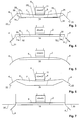
- Fig. 2 einen Schnitt durch eine zweite Ausführung einer Dunstabzugshaube,
- Fig. 3 einen Schnitt durch eine dritte Ausführung einer Dunstabzugshaube,
- Fig. 4 einen Schnitt durch eine vierte Ausführung einer Dunstabzugshaube,
- Fig. 5 einen Schnitt durch eine fünfte Ausführung einer Dunstabzugshaube,
- Fig. 6 einen Schnitt durch eine sechste Ausführung einer Dunstabzugshaube,
- Fig. 7 einen Schnitt durch eine siebte Ausführung einer Dunstabzugshaube,
- Fig. 8 einen Schnitt durch eine achte Ausführung einer Dustabzugshaube und
- Fig. 9 einen Schnitt entlang Linie IX-IX von Fig. 8.
- 1 shows a section through a first embodiment of an extractor hood with arranged below cooking surface,
- 2 shows a section through a second embodiment of an extractor hood,
- 3 shows a section through a third embodiment of an extractor hood,
- 4 shows a section through a fourth embodiment of an extractor hood,
- 5 shows a section through a fifth embodiment of an extractor hood,
- 6 shows a section through a sixth embodiment of an extractor hood,
- 7 shows a section through a seventh embodiment of an extractor hood,
- Fig. 8 is a section through an eighth embodiment of a Dustabzugshaube and
- 9 is a section along line IX-IX of Fig. 8.
Die Dunstabzugshaube 1 nach Fig. 1 besitzt eine horizontale, im wesentlichen flache, für Dunst undurchlässige Stauplatte 2, um welche ein Abzugsbereich 3 in Form einen Schlitzes 3a angeordnet ist. Der Abzugsbereich 3 erstreckt sich im wesentlichen um den ganzen Aussenrand der Stauplatte 2. Ausserhalb des Abzugsbereichs 3 schliesst eine Führungsplatte 4 an, welche sich vom Abzugsbereich 3 nach aussen und schräg nach unten bis an den äusseren Rand der Dunstabzugshaube 1 erstreckt. Die Führungsplatte 4 besteht aus einen oder mehreren Platten, die am Rand der Dunstabzugshaube 1 angeordnet ist bzw. sind, und ist z.B. über einen vertikalen Abschnitt 5 mit einer Deckplatte 6 der Dunstabzugshaube verbunden. Zwischen der Deckplatte 6 und der Stauplatte 2 wird ein Saugraum 7 gebildet. In der Deckplatte 6 ist eine Öffnung 8 vorgesehen, in der ein Fettfilter 9a in Form eines Aluminiumnetzes angeordnet ist. Die Öffnung 8 verbindet den Saugraum 7 mit einem Abluftraum 10, in welchem ein Ventilator 11 vorgesehen ist, der Luft in eine Abluftleitung 12 fördert. Der Ventilator 11 kann auch ausserhalb der Dunstabzugshaube angeordnet sein.The
Über dem Fettfilter 9a kann optional ein Geruchsfilter 9b, z.B. in Form eines Aktivkohlefilters, vorgesehen sein.Over the
Der Abluftraum 10 ist mit einem Abluftsystem 18 verbunden, welches in Fig. 1 schematisch dargestellt ist. Dabei kann es sich um ein einfaches Entlüfungsrohr handeln, das die Abluft direkt in die Umgebung abführt. Es kann sich jedoch auch um den Abluftkanal eines Lüftungssystems des Gebäudes handeln, welches einen eigenen Ventilator 19 besitzt. Das Lüftungssystem kann z.B. die Komfortlüftung eines energieoptimierten Gebäudes sein. Derartige Komfortlüftungen besitzen relativ geringe Förderraten von z.B. 300 m3/h. Prinzipiell ist die vorliegende Dunstabzugshaube schon mit derart tiefen Förderraten funktionsfähig, so dass in diesem Fall auf den Ventilator 11 unter Umständen verzichtet werden kann.The
Insbesondere wenn der Abluftraum 10 mit dem Abluftkanal eines Lüftungssystems des Gebäudes verbunden ist, sollte die Dunstabzugshaube mit einem thermisch aktivierbaren Verschlussmechanismus 9c verbunden werden, der bei den für einen Brand im Herdbereich typischen Temperaturen die Verbindung mit dem Abluftkanal automatisch unterbricht. Dabei kann es sich z.B. um eine konventionelle Brandschutzklappe handeln, welche bei Übertemperatur schliesst. Vorzugsweise wird jedoch ein Verschlussmechanismus mit einem Körper aus intumeszentem Material eingesetzt, der bei Hizeentwicklung sein Volumen z.B. durch Aufschäumen vergrössert und den Durchgang verschliesst.In particular, when the
Vorzugsweise ist der Verschlussmechanismus 9c in die Dunstabzugshaube (als optionaler Zusatz) werkseitig integriert, so dass auf der Baustelle keine weiteren Schritte zum Einbau allfälliger weiterer Komponenten notwendig sind.Preferably, the
Die Stauplatte 2 ist mittels (nicht gezeigten) Befestigungen lösbar in der Dunstabzugshaube angeordnet. Zur Reinigung des Geräts kann sie entfernt werden, so dass der Saugraum 7 zugänglich wird.The
Der an der Kochstelle 13 unterhalb der Dunstabzugshaube 1 erzeugte Dampf steigt zur Dunstabzugshaube 1 auf. Er trifft grösstenteils auf die Stauplatte 2, wo seine vertikale Bewegung in einem Stauraum 14 gestoppt wird. Der Stauraum 14 umfasst einen sich im wesentlichen horizontal erstreckenden Volumenbereich unterhalb der Stauplatte 2. Wie durch Pfeile 15 angedeutet, strömt der Dampf sodann im Stauraum 14 nach aussen in den Abzugsbereich 3. Ein Teil des Dampfs tritt dort direkt in den Schlitz 3a ein. Insbesondere wenn viel Dampf vorhanden ist, wird jedoch ein weiterer Teil des Dampfes nach aussen gedrängt. Er läuft auf der Führungsplatte 4 auf und wird dabei sanft nach unten abgelenkt. Dabei kommt es, wie durch Pfeile 16 angedeutet, zur Bildung von Wirbeln, in denen der Dampf zurück zum Abzugsbereich 3 geführt wird. Gleichzeitig ziehen die Wirbel auch, wie mit Pfeil 17 illustriert, von unten kommenden, relativ weit aussen aufsteigenden Dampf mit.The steam generated at the
Der durch den Schlitz 3a in den Saugraum 7 tretende Dampf wird vom Ventilator 11 durch das Fettfilter 9 gesogen und der Abluftleitung 12 zugeführt.The passing through the
Untersuchungen haben gezeigt, dass die erwähnte Wirbelbildung unter typischen Verhältnissen, wie sie bei Haushaltskochstellen auftreten, zustande kommt, wenn die Führungsplatte eine Breite B von mindestens 5 cm hat, wobei beste Ergebnisse bei einer Breite von ca. 10 bis 20 cm erzielt wurden. Der Neigungswinkel α sollte zwischen 15° bis 75°, möglichst zwischen 30° und 60° liegen, wobei beste Ergebnisse bei einem Winkel von ca. 45° erzielt wurden.Studies have shown that the mentioned vortex formation under typical conditions, as occurs in home cooking, comes about when the guide plate has a width B of at least 5 cm, with best results were achieved with a width of about 10 to 20 cm. The inclination angle α should be between 15 ° to 75 °, if possible between 30 ° and 60 °, with best results being achieved at an angle of about 45 °.
Um einen möglichst guten Abzug von Dunst zu gewährleisten, sollte die Dunstabzugshaube 2 die Kochstelle 13 seitlich überragen. (Bei einer Wandmontage ist ein wandseitiges Überragen allerdings nicht notwendig.) Vorzugsweise beträgt der Winkel γ zwischen der Vertikalen und einer Verbindungslinie zwischen dem Rand der Kochstelle 13 und dem Rand der Führungsplatte 4 mindestens 8° bei einer Wandmontage der Dunstabzugshaube 2 und mindestens 12° bei einer allseitig freien Montage (d.h. bei einer "Kochinsel").To ensure the best possible deduction of haze, the
Der vertikale Abstand h zwischen der Kochstelle 13 und der Dunstabzugshaube 2 sollte vorzugsweise nicht grösser als 600 mm sein.The vertical distance h between the
Starke Querluftströmungen grösser als 0.2 m/s im Bereich zwischen Kochstelle 13 und Dunstabzugshaube 2 können die Effizienz der Dunstabzugshaube beeinträchtigen.Strong cross-air flows greater than 0.2 m / s in the area between the
Eine zweite Ausführung der Vorrichtung ist in Fig. 2 dargestellt. Sie unterscheidet sich von jener nach Fig. 1 dadurch, dass sie ein Gehäuse 20 besitzt, welches die Führungsplatte 4 seitlich und nach oben umschliesst. Zudem erstreckt sich die Führungsplatte 4 schräg bis zur Deckplatte 6.A second embodiment of the device is shown in FIG. It differs from that of FIG. 1 in that it has a
Die Ausführung nach Fig. 3 illustriert Massnahmen zum Auffangen von kondensiertem Wasser. Hier ist am Aussenrand der Führungsplatte 4 ein erster Tropfenfänger 22 zum Auffangen von an der Führungsplatte 4 kondensiertem Wasser angeordnet. Er wird durch einen nach innen und oben abgebogenen Randbereich der Führungsplatte 4 gebildet.The embodiment of Fig. 3 illustrates measures for collecting condensed water. Here, a
Ein zweiter Tropfenfänger 24 ist am Aussenrand der Stauplatte 2 vorgesehen. Er dient zum Auffangen von im Abzugsbereich oder oberhalb der Stauplatte 2 kondensiertem Wasser und wird durch den nach oben abgebogenen Rand der Stauplatte 2 gebildet.A
Weiter ist entlang des Aussenrands der Stauplatte 2 eine sich nach oben und aussen erstreckende Leitplatte 26 vorgesehen. Sie dient zum Auffangen von Wasser, welches im Randbereich der Deckplatte 6 kondensiert und nach unten tropft. Die Innenkante 28 der Führungsplatte 26 befindet sich oberhalb und über der Stauplatte 2, so dass von dort abtropfendes Wasser von der Stauplatte 2 aufgefangen wird.Further, along the outer edge of the
Wie ebenfalls aus Fig. 3 ersichtlich, ist die Deckplatte 6 gegen die Mitte der Dunstabzugshaube hin nach unten geneigt. Dadurch läuft das an der Deckplatte 6 kondensierte Wasser zumindest zu einem grossen Teil gegen die Mitte hin weg, von wo es abtropft und auf die Stauplatte 2 bzw. in die über der Stauplatte 2 gebildete Wanne 29 fällt, wobei der Boden der Wanne 29 (wie in Fig. 3 gezeigt) von einem sich zwischen der Führungsplatten 26 erstreckenden Blech oder (nicht gezeigt) von der Stauplatte 2 selbst gebildet werden kann.As also seen from Fig. 3, the
In der Ausführung nach Fig. 4 sind an der Innenseite der Führungsplatte 4 mehrere sich nach innen und oben erstreckende, im wesentlichen horizontal verlaufende Rippen 31 vorgesehen. Sie dienen einerseits zum Auffangen von Kondensat, und andererseits verbessern sie die Bremswirkung, welche die Führungsplatte 4 auf den nach aussen strömenden Dampf ausübt.In the embodiment of Fig. 4, a plurality of inwardly and upwardly extending, substantially horizontally extending
Die Ausführung nach Fig. 4 zeigt zudem eine (unabhängig von den Rippen 31 verwendbare) weitere Massnahme zur Kontrolle des Kondensats von Fett und Wasser. Dabei wird im Saugraum 7 parallel zum Spalt 3a eine Verengung 32 gebildet, welche der angesaugte Wrasen passieren muss. Die in der Verengung 32 erzeugten Beschleunigungen führen dazu, dass Fett- und Wassertropfen oder andere Schwebeteilchen aus dem Gasstrom gegen die Wände geworfen und so abgeschieden werden.The embodiment according to FIG. 4 also shows a further measure (which can be used independently of the ribs 31) for controlling the condensate of fat and water. In this case, a
Vorzugsweise wird die Verengung durch eine Rippe 33 gebildet, welche von oben in den Saugraum 7 ragt. Dabei sollte die Rippe 33 über der Stauplatte 2 angeordnet sein, damit von der Rippe 33 abtropfendes Kondensat von der Stauplatte 2 aufgefangen werden kann.Preferably, the constriction is formed by a
Fig. 5 illustriert, dass die Führungsplatte 4 auch gebogen ausgeführt sein kann. Durch die Biegung, bei welcher der Neigungswinkel der Führungsplatte 4 nach aussen hin zunimmt (d.h. steiler wird), wird die Wirbelbildung begünstigt. Im gezeigten Ausführungsbeispiel geht die Führungsplatte 4 gegen innen direkt in die Deckplatte 6 über.Fig. 5 illustrates that the
Fig. 6 zeigt, dass die Stauplatte 2 nicht eben ausgestaltet sein muss. Sie kann z.B. die Form einer Wanne haben. Sie kann auch leicht schräg angeordnet sein, z.B. nur an ihren Rändern (wie in Fig. 6 gezeigt) oder über ihre ganze Fläche. Sie sollte jedoch im wesentlichen horizontal angeordnet sein, damit sie die vertikale Bewegung des Dunstes im Stauraum 14 im wesentlichen abzustoppen vermag. Vorzugsweise sollte sie deshalb, über ihre Gesamtfläche gesehen, einen Neigungswinkel von höchstens 10° gegenüber der Horizontalen besitzen. Sie kann jedoch insbesondere lokal z.B. auch einzelne Facetten aufweisen, die einen grösseren Neigungswinkel besitzen.Fig. 6 shows that the
Die Dunstabzugshaube 1 kann, von oben gesehen, rechteckige, runde, ovale, halbrunde oder andere Form haben.The
Die Führungsplatte 4 erstreckt sich bei frei montierten Dunstabzugshauben vorzugsweise um den ganzen Abzugsbereich 3, d.h. um das ganze Gerät herum, so dass es überall zur genannten Wirbelbildung kommt. Bei Geräten, die zur Wandmontage vorgesehen sind, ist gegen die Wand hin eine Führungsplatte 4 nicht unbedingt notwendig. Bei, von oben gesehen, rechteckigen Geräten erstreckt sich die Führungsplatte somit vorzugsweise entlang drei oder vier Aussenseiten. Für die Einbaumontage kann jedoch auch nur nach vorne eine Führungsplatte vorgesehen sein.The
Bei der Ausführung nach Fig. 7 handelt es sich ebenfalls um ein Gerät zur Einbaumontage, welches zwischen zwei an der Wand aufgehängten Küchenmöbeln 30 angeordnet ist. In dieser Ausführung erstreckt sich die Führungsplatte 4 unter die benachbarten Küchenmöbel 30, sowie (nicht gezeigt) nach vorne gegen den Benutzer hin. Diese Ausführung kann auch, wie von konventionellen Geräten her bekannt, ausziehbar gestaltet werden.In the embodiment of Fig. 7 is also a device for flush mounting, which is arranged between two hung on the
Die Teile der Dunstabzugshaube 1, so z.B. die Stauplatte 2 und die Führungsplatte 4 können aus Metallblechen gefertigt sein. Es kann sich jedoch auch um Kunststoffteile handeln.The parts of the
Fig. 8 und 9 zeigen eine weitere Ausführung der Erfindung. Wie aus Fig. 9 erkennbar, ist diese Ausführung zur Wandmontage ausgestaltet, das gleiche Konstruktionsprinzip kann jedoch auch zur allseitig freien Montage eingesetzt werden.Figs. 8 and 9 show another embodiment of the invention. As can be seen from FIG. 9, this embodiment is configured for wall mounting, but the same design principle can also be used for free assembly on all sides.
Erkennbar sind in Fig. 8 und 9 insbesondere die mit nach oben abgeschrägten Rändern wannenförmig ausgestaltete Stauplatte 2 über dem Stauraum 14, die Führungsplatte 4 und der Abluftraum 10. Weiter ersichtlich ist auch die Rippe 33, welche dem Schlitz 3a entlang verläuft. Weiter ist der Befestigungsmechanismus 35 dargestellt, über welchen die Stauplatte 2 abnehmbar an der Deckplatte 6 befestigt ist. Schliesslich ist in der Führungsplatte 4 eine Beleuchtung 36 integriert.Evident are in Fig. 8 and 9 in particular the upwardly tapered edges trough-shaped
Die verschiedenen, in den Ausführungsbeispielen gemäss Fig. 1 bis 9 gezeigten Elemente der Dunstabzugshaube können beliebig miteinander kombiniert werden. So können beispielsweise der Tropfenfänger 22 gemäss Fig. 3 bzw. die Rippen 31 oder 33 gemäss Fig. 4 auch in den Ausführungsbeispielen der übrigen Figuren eingesetzt werden.The various elements of the extractor hood shown in the embodiments according to FIGS. 1 to 9 can be combined with each other as desired. Thus, for example, the
Claims (19)
dadurch gekennzeichnet, dass die Dunstabzugshaube (2) die Kochstelle (13) seitlich überragt, und insbesondere dass ein Winkel (γ) zwischen der Vertikalen und einer Verbindungslinie zwischen dem Rand der Kochstelle und dem Rand der Führungsplatte (4) mindestens 8° bei einer Wandmontage der Dunstabzugshaube (2) und mindestens 12° bei einer allseitig freien Montage beträgt und/oder
dadurch gekennzeichnet, dass ein vertikaler Abstand (h) zwischen der Kochstelle (13) und der Dunstabzugshaube (2) nicht grösser als 600 mm ist.Cooking station with an extractor hood according to one of the preceding claims,
characterized in that the extractor hood (2) the cooking point (13) laterally surmounted, and in particular that an angle (γ) between the vertical and a connecting line between the edge of the cooking area and the edge of the guide plate (4) is at least 8 ° in a wall mounting of the hood (2) and at least 12 ° in a free mounting on all sides and / or
characterized in that a vertical distance (h) between the cooking position (13) and the extractor hood (2) is not greater than 600 mm.
Applications Claiming Priority (1)
| Application Number | Priority Date | Filing Date | Title |
|---|---|---|---|
| CH13032004A CH704954B1 (en) | 2004-08-04 | 2004-08-04 | Extractor hood to be placed over a hotplate. |
Publications (2)
| Publication Number | Publication Date |
|---|---|
| EP1624254A1 true EP1624254A1 (en) | 2006-02-08 |
| EP1624254B1 EP1624254B1 (en) | 2010-09-01 |
Family
ID=35219562
Family Applications (1)
| Application Number | Title | Priority Date | Filing Date |
|---|---|---|---|
| EP20050004532 Not-in-force EP1624254B1 (en) | 2004-08-04 | 2005-03-02 | Exhausting hood to be arranged above a cooking area |
Country Status (3)
| Country | Link |
|---|---|
| EP (1) | EP1624254B1 (en) |
| CH (1) | CH704954B1 (en) |
| DE (1) | DE502005010164D1 (en) |
Cited By (15)
| Publication number | Priority date | Publication date | Assignee | Title |
|---|---|---|---|---|
| EP1818622A1 (en) * | 2006-02-14 | 2007-08-15 | V-Zug AG | Fume extractor hood with removable inserts |
| DE102006041582A1 (en) * | 2006-09-05 | 2008-03-06 | BSH Bosch und Siemens Hausgeräte GmbH | Extractor hood for stove in cooking area, has moisture shield with horizontally extending central unit and wing provided at external side of unit, and illuminant provided in wing that is pivotably and movably connected with central unit |
| DE102006055001A1 (en) * | 2006-11-17 | 2008-05-21 | Bohner Produktions Gmbh | Dunstabsaugeinrichtung |
| EP2093500A1 (en) * | 2008-02-25 | 2009-08-26 | BSH Bosch und Siemens Hausgeräte GmbH | Exhauster hood |
| EP2420738A1 (en) * | 2010-08-17 | 2012-02-22 | BSH Bosch und Siemens Hausgeräte GmbH | Air guidance unit for the suction opening of an extractor hood |
| JP2012180949A (en) * | 2011-02-28 | 2012-09-20 | Toyo Kitchen & Living Co Ltd | Range hood for smoke emission |
| EP2565543A1 (en) * | 2011-08-31 | 2013-03-06 | Miele & Cie. KG | Vapour extraction device with a filter cover plate |
| EP2829808A1 (en) | 2013-07-23 | 2015-01-28 | V-Zug AG | Extractor hood |
| CN104595958A (en) * | 2015-01-29 | 2015-05-06 | 广东美的厨房电器制造有限公司 | Extractor hood |
| CN104964327A (en) * | 2015-07-29 | 2015-10-07 | 中山市雅西环保科技有限公司 | Smoke exhaust ventilator |
| NO20151237A1 (en) * | 2014-09-22 | 2016-03-23 | Thermex Scandinavia As | Avsugsinnretning |
| DE102015100557A1 (en) * | 2015-01-15 | 2016-07-21 | Miele & Cie. Kg | Hood |
| EP3081865A3 (en) * | 2010-01-13 | 2017-03-01 | OY Halton Group, Ltd. | Oven exhaust hood methods and device |
| WO2020260344A1 (en) * | 2019-06-26 | 2020-12-30 | Inovvida Aero Ip Ug (Haftungsbeschränkt) | Device for extracting vapours, and method for extracting vapours by means of the device, and use of the device to extract vapours |
| EP2772695B1 (en) * | 2014-06-27 | 2021-04-21 | V-Zug AG | Extractor hood |
Citations (6)
| Publication number | Priority date | Publication date | Assignee | Title |
|---|---|---|---|---|
| GB1591451A (en) * | 1976-11-11 | 1981-06-24 | Kemtron Properties Pty Ltd | Extractor vents |
| DE4441788A1 (en) * | 1994-11-24 | 1996-05-30 | Reinhard Grunow | Extraction hood for cookers |
| DE10000841A1 (en) | 2000-01-12 | 2001-07-19 | Max Homeier | Fumes extractor hood has rectangular base surface, grease-collector dish, filter arrangement, chimney with housing, motor and fan |
| DE10012889A1 (en) | 2000-03-16 | 2001-09-27 | Exklusiv Hauben Gutmann Gmbh | Cooker hood has additional suction surface behind first suction surface at edge of cooker hood and has air flow path to conduct cooking fumes from suction surfaces to exhaust line |
| DE10209693A1 (en) * | 2002-03-06 | 2003-09-18 | Manfred H Langner | Cleaning process for waste air from extractor hoods in large kitchens uses extractor fan with curved intake channel, to deflect intake air along curved surface and through sprayed cleaning fluid |
| DE10255317A1 (en) * | 2002-11-27 | 2004-06-09 | Langner, Manfred H. | Moisture extractor hood, e.g. for kitchen, has collecting gutter fitted to housing so that it can be removed |
-
2004
- 2004-08-04 CH CH13032004A patent/CH704954B1/en unknown
-
2005
- 2005-03-02 DE DE200550010164 patent/DE502005010164D1/en active Active
- 2005-03-02 EP EP20050004532 patent/EP1624254B1/en not_active Not-in-force
Patent Citations (6)
| Publication number | Priority date | Publication date | Assignee | Title |
|---|---|---|---|---|
| GB1591451A (en) * | 1976-11-11 | 1981-06-24 | Kemtron Properties Pty Ltd | Extractor vents |
| DE4441788A1 (en) * | 1994-11-24 | 1996-05-30 | Reinhard Grunow | Extraction hood for cookers |
| DE10000841A1 (en) | 2000-01-12 | 2001-07-19 | Max Homeier | Fumes extractor hood has rectangular base surface, grease-collector dish, filter arrangement, chimney with housing, motor and fan |
| DE10012889A1 (en) | 2000-03-16 | 2001-09-27 | Exklusiv Hauben Gutmann Gmbh | Cooker hood has additional suction surface behind first suction surface at edge of cooker hood and has air flow path to conduct cooking fumes from suction surfaces to exhaust line |
| DE10209693A1 (en) * | 2002-03-06 | 2003-09-18 | Manfred H Langner | Cleaning process for waste air from extractor hoods in large kitchens uses extractor fan with curved intake channel, to deflect intake air along curved surface and through sprayed cleaning fluid |
| DE10255317A1 (en) * | 2002-11-27 | 2004-06-09 | Langner, Manfred H. | Moisture extractor hood, e.g. for kitchen, has collecting gutter fitted to housing so that it can be removed |
Cited By (23)
| Publication number | Priority date | Publication date | Assignee | Title |
|---|---|---|---|---|
| EP1818622A1 (en) * | 2006-02-14 | 2007-08-15 | V-Zug AG | Fume extractor hood with removable inserts |
| DE102006041582A1 (en) * | 2006-09-05 | 2008-03-06 | BSH Bosch und Siemens Hausgeräte GmbH | Extractor hood for stove in cooking area, has moisture shield with horizontally extending central unit and wing provided at external side of unit, and illuminant provided in wing that is pivotably and movably connected with central unit |
| DE102006055001A1 (en) * | 2006-11-17 | 2008-05-21 | Bohner Produktions Gmbh | Dunstabsaugeinrichtung |
| WO2008058761A2 (en) * | 2006-11-17 | 2008-05-22 | Bohner Produktions Gmbh | Fume extracting device |
| WO2008058761A3 (en) * | 2006-11-17 | 2008-12-24 | Bohner Produktions Gmbh | Fume extracting device |
| DE102008011020A1 (en) * | 2008-02-25 | 2009-08-27 | BSH Bosch und Siemens Hausgeräte GmbH | Exhaust hood |
| EP2093500A1 (en) * | 2008-02-25 | 2009-08-26 | BSH Bosch und Siemens Hausgeräte GmbH | Exhauster hood |
| EP3081865A3 (en) * | 2010-01-13 | 2017-03-01 | OY Halton Group, Ltd. | Oven exhaust hood methods and device |
| US11137146B2 (en) | 2010-01-13 | 2021-10-05 | Oy Halton Group Ltd. | Oven exhaust hood methods, devices, and systems |
| US10215421B2 (en) | 2010-01-13 | 2019-02-26 | Oy Halton Group Ltd. | Oven exhaust hood methods, devices, and systems |
| US9777929B2 (en) | 2010-01-13 | 2017-10-03 | Oy Halton Group Ltd. | Oven exhaust hood methods, devices, and systems |
| EP2420738A1 (en) * | 2010-08-17 | 2012-02-22 | BSH Bosch und Siemens Hausgeräte GmbH | Air guidance unit for the suction opening of an extractor hood |
| JP2012180949A (en) * | 2011-02-28 | 2012-09-20 | Toyo Kitchen & Living Co Ltd | Range hood for smoke emission |
| EP2565543A1 (en) * | 2011-08-31 | 2013-03-06 | Miele & Cie. KG | Vapour extraction device with a filter cover plate |
| EP2829808A1 (en) | 2013-07-23 | 2015-01-28 | V-Zug AG | Extractor hood |
| EP2772695B1 (en) * | 2014-06-27 | 2021-04-21 | V-Zug AG | Extractor hood |
| NO20151237A1 (en) * | 2014-09-22 | 2016-03-23 | Thermex Scandinavia As | Avsugsinnretning |
| NO343800B1 (en) * | 2014-09-22 | 2019-06-11 | Thermex Scandinavia As | Avsugsinnretning |
| DE102015100557A1 (en) * | 2015-01-15 | 2016-07-21 | Miele & Cie. Kg | Hood |
| CN104595958B (en) * | 2015-01-29 | 2016-09-28 | 广东美的厨房电器制造有限公司 | Range hood |
| CN104595958A (en) * | 2015-01-29 | 2015-05-06 | 广东美的厨房电器制造有限公司 | Extractor hood |
| CN104964327A (en) * | 2015-07-29 | 2015-10-07 | 中山市雅西环保科技有限公司 | Smoke exhaust ventilator |
| WO2020260344A1 (en) * | 2019-06-26 | 2020-12-30 | Inovvida Aero Ip Ug (Haftungsbeschränkt) | Device for extracting vapours, and method for extracting vapours by means of the device, and use of the device to extract vapours |
Also Published As
| Publication number | Publication date |
|---|---|
| CH704954B1 (en) | 2012-11-30 |
| DE502005010164D1 (en) | 2010-10-14 |
| EP1624254B1 (en) | 2010-09-01 |
Similar Documents
| Publication | Publication Date | Title |
|---|---|---|
| EP1624254B1 (en) | Exhausting hood to be arranged above a cooking area | |
| DE2607301C2 (en) | Extractor hood | |
| DE102008033792B4 (en) | Air circulation module and extractor device | |
| EP3338031B1 (en) | Combined device with cooking hob and vapour extraction unit | |
| EP3475622B1 (en) | Downdraft ventilation system with an insert | |
| DE102005030038B4 (en) | Cooktop extractor | |
| CH682512A5 (en) | Steam extractor hood for cooking hob - has ventilation fan providing air curtain around hub surface to prevent mixing between steam and room air | |
| DE10325007A1 (en) | Extractor hood for a kitchen stove | |
| DE102008020149A1 (en) | Filter unit for a fume extractor and fume extractor | |
| DE202018006721U1 (en) | Fume hood for extracting exhaust air generated on a hob in a direction pointing vertically below a hob level | |
| DE102005019830A1 (en) | Kitchen cooker exhaust hood has truncated pyramid filter insert with central hole to trap collector | |
| DE102017216456A1 (en) | Ventilation device for hob and hob with ventilation device | |
| EP2210048B1 (en) | Extractor device | |
| EP2334988B1 (en) | Extractor hood | |
| DE202015104361U1 (en) | Extractor hood for a cooking appliance and cooking appliance with such an extractor hood | |
| EP2677242B1 (en) | Device for extraction of air | |
| DE202011110040U1 (en) | Device for extracting gases and / or smoke | |
| DE102011080485B4 (en) | Device for extracting air from a hob | |
| EP3710756A1 (en) | Range hood device for a cooktop and kitchen furniture with range hood device | |
| DE19950817A1 (en) | Extractor hood | |
| DE102017120193B4 (en) | Cooking element | |
| DE3904383C2 (en) | Electric extractor hood | |
| EP3574265B1 (en) | Extractor hood | |
| WO2009106548A2 (en) | Range hood device and method for purifying kitchen air | |
| EP2829808A1 (en) | Extractor hood |
Legal Events
| Date | Code | Title | Description |
|---|---|---|---|
| PUAI | Public reference made under article 153(3) epc to a published international application that has entered the european phase |
Free format text: ORIGINAL CODE: 0009012 |
|
| AK | Designated contracting states |
Kind code of ref document: A1 Designated state(s): AT BE BG CH CY CZ DE DK EE ES FI FR GB GR HU IE IS IT LI LT LU MC NL PL PT RO SE SI SK TR |
|
| AX | Request for extension of the european patent |
Extension state: AL BA HR LV MK YU |
|
| 17P | Request for examination filed |
Effective date: 20060330 |
|
| AKX | Designation fees paid |
Designated state(s): CH DE FR IT LI |
|
| 17Q | First examination report despatched |
Effective date: 20090625 |
|
| GRAP | Despatch of communication of intention to grant a patent |
Free format text: ORIGINAL CODE: EPIDOSNIGR1 |
|
| GRAS | Grant fee paid |
Free format text: ORIGINAL CODE: EPIDOSNIGR3 |
|
| GRAA | (expected) grant |
Free format text: ORIGINAL CODE: 0009210 |
|
| AK | Designated contracting states |
Kind code of ref document: B1 Designated state(s): CH DE FR IT LI |
|
| REG | Reference to a national code |
Ref country code: CH Ref legal event code: NV Representative=s name: E. BLUM & CO. AG PATENT- UND MARKENANWAELTE VSP Ref country code: CH Ref legal event code: EP |
|
| REF | Corresponds to: |
Ref document number: 502005010164 Country of ref document: DE Date of ref document: 20101014 Kind code of ref document: P |
|
| PLBE | No opposition filed within time limit |
Free format text: ORIGINAL CODE: 0009261 |
|
| STAA | Information on the status of an ep patent application or granted ep patent |
Free format text: STATUS: NO OPPOSITION FILED WITHIN TIME LIMIT |
|
| 26N | No opposition filed |
Effective date: 20110606 |
|
| REG | Reference to a national code |
Ref country code: DE Ref legal event code: R097 Ref document number: 502005010164 Country of ref document: DE Effective date: 20110606 |
|
| REG | Reference to a national code |
Ref country code: FR Ref legal event code: PLFP Year of fee payment: 12 |
|
| REG | Reference to a national code |
Ref country code: FR Ref legal event code: PLFP Year of fee payment: 13 |
|
| REG | Reference to a national code |
Ref country code: FR Ref legal event code: PLFP Year of fee payment: 14 |
|
| PGFP | Annual fee paid to national office [announced via postgrant information from national office to epo] |
Ref country code: CH Payment date: 20180202 Year of fee payment: 14 Ref country code: DE Payment date: 20180322 Year of fee payment: 14 |
|
| PGFP | Annual fee paid to national office [announced via postgrant information from national office to epo] |
Ref country code: FR Payment date: 20180323 Year of fee payment: 14 |
|
| PGFP | Annual fee paid to national office [announced via postgrant information from national office to epo] |
Ref country code: IT Payment date: 20180327 Year of fee payment: 14 |
|
| REG | Reference to a national code |
Ref country code: DE Ref legal event code: R119 Ref document number: 502005010164 Country of ref document: DE |
|
| REG | Reference to a national code |
Ref country code: CH Ref legal event code: PL |
|
| PG25 | Lapsed in a contracting state [announced via postgrant information from national office to epo] |
Ref country code: CH Free format text: LAPSE BECAUSE OF NON-PAYMENT OF DUE FEES Effective date: 20190331 Ref country code: LI Free format text: LAPSE BECAUSE OF NON-PAYMENT OF DUE FEES Effective date: 20190331 Ref country code: DE Free format text: LAPSE BECAUSE OF NON-PAYMENT OF DUE FEES Effective date: 20191001 |
|
| PG25 | Lapsed in a contracting state [announced via postgrant information from national office to epo] |
Ref country code: FR Free format text: LAPSE BECAUSE OF NON-PAYMENT OF DUE FEES Effective date: 20190331 Ref country code: IT Free format text: LAPSE BECAUSE OF NON-PAYMENT OF DUE FEES Effective date: 20190302 |