EP1624106A1 - Auftragsvorrichtung - Google Patents
Auftragsvorrichtung Download PDFInfo
- Publication number
- EP1624106A1 EP1624106A1 EP05105847A EP05105847A EP1624106A1 EP 1624106 A1 EP1624106 A1 EP 1624106A1 EP 05105847 A EP05105847 A EP 05105847A EP 05105847 A EP05105847 A EP 05105847A EP 1624106 A1 EP1624106 A1 EP 1624106A1
- Authority
- EP
- European Patent Office
- Prior art keywords
- counter
- doctor
- roller
- applicator
- base frame
- Prior art date
- Legal status (The legal status is an assumption and is not a legal conclusion. Google has not performed a legal analysis and makes no representation as to the accuracy of the status listed.)
- Granted
Links
- 239000011248 coating agent Substances 0.000 title claims abstract description 16
- 238000000576 coating method Methods 0.000 title claims abstract description 16
- 239000007788 liquid Substances 0.000 claims abstract description 3
- 235000011837 pasties Nutrition 0.000 claims description 2
- 238000000034 method Methods 0.000 description 3
- 239000007921 spray Substances 0.000 description 3
- 239000000725 suspension Substances 0.000 description 3
- 230000008901 benefit Effects 0.000 description 2
- 238000004140 cleaning Methods 0.000 description 2
- 238000010276 construction Methods 0.000 description 2
- 238000012423 maintenance Methods 0.000 description 2
- 230000008569 process Effects 0.000 description 2
- 230000008439 repair process Effects 0.000 description 2
- 229920002472 Starch Polymers 0.000 description 1
- 210000001015 abdomen Anatomy 0.000 description 1
- 238000013459 approach Methods 0.000 description 1
- 230000008859 change Effects 0.000 description 1
- 238000013461 design Methods 0.000 description 1
- 239000006185 dispersion Substances 0.000 description 1
- 238000009432 framing Methods 0.000 description 1
- 230000009931 harmful effect Effects 0.000 description 1
- 239000000463 material Substances 0.000 description 1
- 230000013011 mating Effects 0.000 description 1
- 238000012544 monitoring process Methods 0.000 description 1
- 239000003973 paint Substances 0.000 description 1
- 230000002093 peripheral effect Effects 0.000 description 1
- 238000005096 rolling process Methods 0.000 description 1
- 238000007493 shaping process Methods 0.000 description 1
- 235000019698 starch Nutrition 0.000 description 1
- 239000008107 starch Substances 0.000 description 1
- 239000004753 textile Substances 0.000 description 1
- 238000012546 transfer Methods 0.000 description 1
Images

Classifications
-
- D—TEXTILES; PAPER
- D21—PAPER-MAKING; PRODUCTION OF CELLULOSE
- D21H—PULP COMPOSITIONS; PREPARATION THEREOF NOT COVERED BY SUBCLASSES D21C OR D21D; IMPREGNATING OR COATING OF PAPER; TREATMENT OF FINISHED PAPER NOT COVERED BY CLASS B31 OR SUBCLASS D21G; PAPER NOT OTHERWISE PROVIDED FOR
- D21H23/00—Processes or apparatus for adding material to the pulp or to the paper
- D21H23/02—Processes or apparatus for adding material to the pulp or to the paper characterised by the manner in which substances are added
- D21H23/22—Addition to the formed paper
- D21H23/32—Addition to the formed paper by contacting paper with an excess of material, e.g. from a reservoir or in a manner necessitating removal of applied excess material from the paper
-
- D—TEXTILES; PAPER
- D21—PAPER-MAKING; PRODUCTION OF CELLULOSE
- D21H—PULP COMPOSITIONS; PREPARATION THEREOF NOT COVERED BY SUBCLASSES D21C OR D21D; IMPREGNATING OR COATING OF PAPER; TREATMENT OF FINISHED PAPER NOT COVERED BY CLASS B31 OR SUBCLASS D21G; PAPER NOT OTHERWISE PROVIDED FOR
- D21H25/00—After-treatment of paper not provided for in groups D21H17/00 - D21H23/00
- D21H25/08—Rearranging applied substances, e.g. metering, smoothing; Removing excess material
- D21H25/10—Rearranging applied substances, e.g. metering, smoothing; Removing excess material with blades
Definitions
- the invention relates to a device for direct or indirect application of a liquid or pasty coating medium on a running paper, cardboard or other Fasterstoffbahn.
- the fibrous web can also be a textile web.
- the web can be coated on one side or on both sides.
- the coating medium can be applied in one or more layers. It may be, for example, a paint, a starch, an impregnating material or others, each in the form of a suspension or dispersion.
- the essential components of such a device are a counter-roller, a commissioning unit associated therewith for applying the coating medium and a squeegee device.
- the commissioned work applies coating medium as a flat jet.
- the beam can be as wide as the web itself. It can also have a slightly smaller width or form the application layer in the form of a large number of individual beams.
- the squeegee device is connected downstream of the commissioned work. It serves for the uniform and / or the dosage of the applied layer of coating medium.
- the fibrous web wraps around the counter roll on a portion of its circumference.
- the medium delivered by the commissioned work passes directly, ie directly onto the web to be crossed.
- the jet of the coating medium is applied to the lateral surface of the counter-roller, in turn uniformed by the doctor device, and then delivered to the fibrous web, which in turn to the Lateral surface of the counter roll is introduced.
- devices with two counter-rollers are known, which form a gap with each other. The fibrous web is passed through this gap, so that the transfer of the layer of coating medium takes place in the region of the nip.
- the counter-roller is stored in a chair.
- the chair has two supporting structures, which according to the counter roll between them. Each support structure is thus located in the region of one end face of the counter-roller.
- the commissioned work and the squeegee device are carried by the chair. Each end of one of these two elements - commissioned work and doctor device - is supported in the associated supporting structure.
- the two supporting structures are rigidly connected to one another by one or more parts of the frame in order to give the frame the necessary rigidity.
- Both the commissioned work and the doctor device must be able to be moved away from the counter-roller into a stand-by position, for example for the purpose of cleaning, maintenance or repair. Of course, they also have to be adjustable into an operating position. It depends on various operating parameters. These include at the commissioned work, the distance between the application nozzle and the lateral surface of the backing roll (the indirect application) or the fibrous web (direct application), further the angle formed by the free jet of the coating medium with the lateral surface of the backing roll or the fibrous web at Strahlauf Economicstician , In the doctor device, it depends on the contact pressure, with which the respective doctor element is pressed against the lateral surface of the counter roll or to the web, and also to the angle formed by the doctor element with these two. To set the parameters mentioned, the two elements-applicator unit and / or squeegee device-can be rotated about an axis parallel to the axis of the counter-roller or pivotable or otherwise movable relative to the counter-roller.
- a squeegee device is any kind of device into consideration, for example, a device with a doctor blade, an air knife, a doctor bar or a rotary squeegee.
- the stroke must have a certain thickness.
- the thickness profile across the web width must be highly uniform.
- the quality of the stroke surface can play a role.
- These functional elements have an elongated shape. Depending on the web width, they can be between 1 and 11 m long. Due to the mentioned suspension in the frame - on the two lateral supporting structures - a slack can not be avoided due to the dead weight of the relevant functional element. Without further measures, this would mean that the parameters mentioned assume different values across the web width. The distance between the nozzle of the commissioned work and impact point of the free jet would thus be greater in the middle of the web, as at the web edges. The contact pressure of the doctor element of the doctor device would be smaller in the middle of the web than at the web edges.
- Measures have been taken to reduce these harmful effects. These consist in that one dimensioned the associated support beams of commissioned work and doctor device according to increase their moment of resistance. In addition, one tries to compensate for the disadvantages by a corresponding shaping of the respective elements, for example, characterized in that the nozzle of the commissioned work and the doctor element of the doctor device - seen in plan view - have a belly.
- the invention has for its object to make a device according to the preamble of claim 1 such that the quality requirements of the coated fibrous web are fully met.
- the device should be of simple, inexpensive and robust construction.
- the masses of commissioned work and doctor device should be as small as possible. Accessibility for the purpose of monitoring functions, cleaning, maintenance and repair is to be improved.
- the core idea of the invention is to support the applicator unit and / or the doctor device on a stiffening part, which extends transversely to the running direction of the fibrous web and thus parallel to the counter-roller.
- Optimal is the support of both functional elements on a single chair part.
- the part of the chair should be designed accordingly so that it can carry and guide one or both of these functional elements.
- both functional units on a single part of the chair - the already necessary part of the chair is used to carry the functional units.
- the functional units can now be supported on the Funging, instead of only at their ends to the lateral support structures of the chair.
- the support can take place over the entire length of the relevant functional unit. In general, however, it will be sufficient to provide a plurality of support points and, in the least expensive case, only on the driver's and drive sides of the device, on which the functional unit is supported on the chairing part.
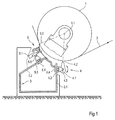
- FIG. 1 shows a counter roller 1. This is rotatably mounted about a rotation axis 1.1. The bearings are not shown here in lateral support structures - one at each end face of the backing roll. 1
- the counter roll 1 is looped by a fibrous web 2 on a part of its peripheral surface.
- a Fung part 3 is designed as a hollow construction. It connects the two mentioned lateral support structures together and establishes a rigid connection to these two.
- the stiffening part 3 carries two functional units, namely a commissioned work 4 and a doctor device 5.
- the commissioned work has a applicator body 4.1.
- a free jet 4.2 or spray jets directed against the fibrous web 2 in operation.
- the commissioned work 4 is mounted by means of a sliding or rolling guide 4.3 on a vertical wall 3.1, the framing part 3 and according to the vertically displaceable - see double arrow 4.4.
- the application body 4.1 is further pivotable about a rotation axis 4.5. In this way, the distance between the application body 4.1 and the fibrous web 2 can be changed, likewise the angle of the free jet 4.2 or the spray jets.
- the doctor device 5 has a doctor body 5.1, which carries a doctor blade 5.2.
- the doctor device 5 is in turn displaceable by means of a sliding guide 5.3 along an inclined wall 3.2 of the Fung part 3. See double arrow 5.4.
- Of the Doctor body 5.1 is pivotable about a rotation axis 5.5. In this way, the squeegee device 5 - equal to the commissioned work 4 - proceed in the direction of the backing roll 1, ie depart from this or hiring against them. Thus, the contact pressure and the angle of the doctor blade 2 can be changed.
- the embodiment according to FIG. 2 has essentially all the features of that according to FIG.
- the Fung part 3 has no closed profile, but is open against the counter roll 1 out. It is also walkable. Furthermore, it has a channel 3.3 for guiding supply lines and a channel 3.4 for catching rubbed-off coating color.
- the functional units 4 and 5 are in turn displaceable or pivotable, as in the embodiment according to FIG. 1. Likewise, the counter-roller 1 can be moved to a stand-by position.
- the commissioned work and doctor device can be designed solely on the basis of the functions to be performed by them.
- the flexural rigidity does not matter because the functional units are supported on the stiffening part, either throughout their entire lengths, or at several points of their lengths.
- the necessary translational movements in the radial direction towards the counter roll - contact pressure, service position - and the pivoting movements with regard to the blade angle, the beam angle and the service position remain unaffected and can be realized properly.
- the stool part could be made wholly or partially movable, but at least the walls or parts of the walls which carry the functional units 4 and 5.
- the fibrous web 2 wraps around the counter roll 1.
- the devices shown can also be used for the indirect application of a coating medium.
- the free jet 4.2 from the application body 4.1 is not applied to the fibrous web 2, but onto the lateral surface of the counter roll 1.
- the layer which deposits thereon is subjected to the doctoring process and transferred at a different point on the circumference of the counter roll 1 onto a fibrous web 2.
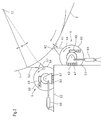
- the device shown in Figure 3 in turn comprises a counter-roller 1 with axis of rotation 1.1.
- the mating roll is also wrapped around a part of its circumference of a fibrous web 2.
- a stiffening part 3 has a vertical surface 3.1 and a horizontal surface 3.2.
- the commissioned work 4 comprises a coating body 4.1, with a nozzle which occupies a certain distance to the fibrous web 2.
- a continuous flat jet 4.2 or a plurality of spray jets of the application medium emerge and reach the fibrous web surface.
- the application body 4.1 is supported by a support beam 4.6. This is cylindrical in the present case.
- the support beam 4.6 is in turn rotatably mounted in bearing blocks 4.7.
- the bearing blocks 4.7 are movable in a sliding guide 4.3 along the vertical surface 3.1 by means of a pneumatic unit 4.8.
- the distance between the nozzle of the nozzle body 4.1 and the fibrous web 2 can be adjusted.
- the adjustment drive 4.9 can be used to change the direction of the application medium 4.2 emerging from the nozzle or a large number of individual nozzles by turning the support beam 4.6.
- the conditions in the doctor device 5 are analogous to those of the commissioned work 4.
- a doctor body 5.1 with doctor blade 5.2 is supported by a support beam 5.6.
- the support beam is in turn stored in bearing blocks 5.7.
- the bearing blocks are movable in a sliding guide 5.3.
- a pneumatic unit 5.8 allows a horizontal approach and retraction of the doctor device 5 relative to the counter cylinder 1.
- An adjusting 5.9 allows a rotation of the support roller 5.6 and thus the angle between the blade 5.2 and fibrous web. 2
Landscapes
- Coating Apparatus (AREA)
- Paper (AREA)
- Massaging Devices (AREA)
Abstract
- eine Gegenwalze (1); ein Auftragswerk (4) zum Auftragen von Streichmedium; eine Rakeleinrichtung (5), die dem Auftragswerk (4) nachgeschaltet ist; sowie eine Stuhlung, umfassend zwei seitliche Tragkonstruktionen zum Lagern der Gegenwalze (1).
Description
- Die Erfindung betrifft eine Vorrichtung zum direkten oder indirekten Auftragen eines flüssigen oder pastösen Streichmediums auf eine laufende Papier-, Karton- oder andere Fasterstoffbahn.
- Bei der Faserstoffbahn kann es sich aber auch um eine textile Bahn handeln. Die Bahn kann dabei einseitig oder beidseitig beschichtet werden. Das Streichmedium kann in einer oder mehreren Schichten aufgetragen werden. Es kann beispielsweise eine Farbe sein, eine Stärke, ein Imprägniermaterial oder anderes, jeweils in Gestalt einer Suspension oder Dispersion.
- Es gibt zahlreiche Ausführungsformen solcher Streichvorrichtungen. Nur beispielsweise wird verwiesen auf DE 196 49 559 A1 oder DE 44 32 179 C1.
- Die wesentlichen Bauteile einer solchen Vorrichtung sind eine Gegenwalze, ein dieser zugeordnetes Auftragswerk zum Auftragen des Streichmediums sowie eine Rakeleinrichtung. Das Auftragswerk trägt Streichmedium als flachen Strahl auf. Der Strahl kann so breit sein, wie die Bahn selbst. Er kann auch eine etwas geringere Breite haben oder in form einer Vielzahl von Einzelstrahlen die Auftragsschicht bilden. Die Rakeleinrichtung ist dem Auftragswerk nachgeschaltet. Sie dient dem Vergleichmäßigen und/oder der Dosierung der aufgetragenen Schicht aus Streichmedium.
- Bei dem direkten Auftragsverfahren umschlingt die Faserstoffbahn die Gegenwalze auf einem Teil von deren Umfang. Das vom Auftragswerk abgegebene Medium gelangt dabei unmittelbar, also direkt auf die zu streichende Bahn. Beim indirekten Auftragsverfahren hingegen wird der Strahl des Streichmediums auf die Mantelfläche der Gegenwalze aufgebracht, wiederum vergleichmäßigt durch die Rakeleinrichtung, und anschließend an die Faserstoffbahn abgegeben, die ihrerseits an die Mantelfläche der Gegenwalze herangeführt wird. Auch sind Vorrichtungen mit zwei Gegenwalzen bekannt, die miteinander einen Spalt bilden. Die Faserstoffbahn wird durch diesen Spalt hindurchgeführt, so dass die Übertragung der Schicht aus Streichmedium im Bereich des Walzenspaltes stattfindet.
- Die Gegenwalze ist in einer Stuhlung gelagert. Die Stuhlung weist zwei Tragkonstruktionen auf, die dem gemäß die Gegenwalze zwischen sich einschließen. Jede Tragkonstruktion befindet sich somit im Bereich einer Stirnseite der Gegenwalze.
- Auch das Auftragswerk und die Rakeleinrichtung sind von der Stuhlung getragen. Jedes Ende einer dieser beiden Elemente - Auftragswerk und Rakeleinrichtung - stützt sich in der zugehörenden Tragkonstruktion ab.
- Die beiden Tragkonstruktionen sind durch eine oder mehrere Stuhlungsteile starr miteinander verbunden, um der Stuhlung die notwendige Steifigkeit zu verleihen.
- Sowohl das Auftragswerk als auch die Rakeleinrichtung müssen von der Gegenwalze in eine Bereitschaftsposition abfahrbar sein, beispielsweise zum Zwecke der Reinigung, der Wartung oder der Reparatur. Sie müssen natürlich auch jeweils in eine Betriebsposition anstellbar sein. Dabei kommt es auf verschiedene Betriebsparameter an. Hierzu gehören beim Auftragswerk der Abstand zwischen der Auftragsdüse und der Mantelfläche der Gegenwalze (beim indirekten Auftrag) bzw. der Faserstoffbahn (beim direkten Auftrag), ferner der Winkel, den der Freistrahl des Auftragsmediums mit der Mantelfläche der Gegenwalze bzw. der Faserstoffbahn am Strahlauftreffpunkt bildet. Bei der Rakeleinrichtung kommt es auf die Anpresskraft an, mit welcher das betreffende Rakelelement an die Mantelfläche der Gegenwalze bzw. an die Bahn angepresst wird, ferner auf den Winkel, den das Rakelelement mit diesen beiden bildet. Zum Einstellen der genannten Parameter können die beiden Elemente - Auftragswerk und/oder Rakeleinrichtung - um eine zur Achse der Gegenwalze parallele Achse verdrehbar oder verschwenkbar oder sonst wie relativ zur Gegenwalze verfahrbar sein.
- Als Rakeleinrichtung kommt jegliche Art von Einrichtung in Betracht, beispielsweise eine Einrichtung mit einer Rakelklinge, einem Luftmesser, einer Rakelleiste oder einem drehbaren Rakelstab.
- An die gestrichene Faserstoffbahn werden hohe Qualitätsanforderungen gestellt. So muss der Strich eine bestimmte Dicke aufweisen. Das Dickenprofil über die Bahnbreite muss in hohem Maße gleichmäßig sein. Die Qualität der Strich-Oberfläche kann eine Rolle spielen.
- Alle diese Qualitätskriterien werden durch die genannten Parameter bestimmt, somit durch die einwandfreie Arbeitsweise und vielseitige Verstellbarkeit der beiden Funktionselemente Auftragswerk und Rakeleinrichtung.
- Diese Funktionselemente haben eine langgestreckte Gestalt. Je nach Bahnbreite können sie zwischen 1 und 11 m lang sein. Wegen der genannten Aufhängung in der Stuhlung - an den beiden seitlichen Tragkonstruktionen - lässt sich ein Durchhang aufgrund des Eigengewichtes des betreffenden Funktionselementes nicht vermeiden. Ohne weitere Maßnahmen würde dies dazu führen, dass die genannten Parameter über die Bahnbreite unterschiedliche Werte annehmen. Der Abstand zwischen Düse des Auftragswerkes und Auftreffpunkt des Freistrahles wäre somit in der Bahnmitte größer, als an den Bahnrändern. Der Anpressdruck des Rakelelementes der Rakeleinrichtung wäre in der Bahnmitte kleiner, als an den Bahnrändern.
- Man hat Maßnahmen getroffen, um diese schädlichen Einflüsse zu verringern. Diese bestehen darin, dass man die zugehörenden Tragbalken von Auftragswerk und Rakeleinrichtung entsprechend dimensioniert, um deren Widerstandsmoment zu vergrößern. Außerdem versucht man die Nachteile durch eine entsprechende Formgebung der betreffenden Elemente zu kompensieren, beispielsweise dadurch, dass die Düse des Auftragswerkes sowie das Rakelelement der Rakeleinrichtung - in Draufsicht gesehen - einen Bauch haben.
- Alle diese Maßnahmen haben sich jedoch als unzulänglich erwiesen.
- Der Erfindung liegt die Aufgabe zugrunde, eine Vorrichtung gemäß dem Oberbegriff von Anspruch 1 derart zu gestalten, dass die Qualitätsanforderungen an die gestrichene Faserstoffbahn voll und ganz erfüllt werden. Außerdem soll die Vorrichtung von einfachem, kostengünstigem und robustem Aufbau sein. Die Massen von Auftragswerk und Rakeleinrichtung sollen möglichst klein sein. Die Zugänglichkeit zum Zwecke der Überwachung der Funktionen, der Reinigung, der Wartung und der Reparatur soll verbessert werden.
- Diese Aufgabe wird durch die Merkmale von Anspruch 1 gelöst.
- Der Kerngedanke der Erfindung besteht darin, das Auftragswerk und/oder die Rakeleinrichtung auf einem Stuhlungsteil abzustützen, das sich quer zur Laufrichtung der Faserstoffbahn und somit parallel zur Gegenwalze erstreckt. Optimal ist die Abstützung beider Funktionselemente auf einem einzigen Stuhlungsteil. Das Stuhlungsteil ist natürlich entsprechend zu gestalten, so dass sie das eine oder beide dieser Funktionselemente zu tragen und zu führen vermag.
- Aufgrund einer solchen Gestaltung wird im Einzelnen Folgendes erreicht:
- Bei der bevorzugten Ausführungsform - beide Funktionseinheiten auf einem einzigen Stuhlungsteil - wird das ohnehin notwendige Stuhlungsteil ausgenutzt, um die Funktionseinheiten zu tragen. Die Funktionseinheiten können sich nunmehr auf dem Stuhlungsteil abstützen, statt nur an ihren Enden an den seitlichen Tragkonstruktionen der Stuhlung. Die Abstützung kann auf der gesamten Länge der betreffenden Funktionseinheit erfolgen. Es wird im Allgemeinen aber genügen, mehrere Auflagerpunkte und im am wenigsten aufwändigsten Fall nur an Führer- und Triebseite der Vorrichtung vorzusehen, an welchen sich die Funktionseinheit auf dem Stuhlungsteil abstützt.
- Die Erfindung ist anhand der Zeichnung näher erläutert. Darin ist im Einzelnen folgendes dargestellt:
- Figur 1
- zeigt eine erste Ausführungsform mit einem Stuhlungsteil mit geschlossenem Kastenprofil.
- Figur 2
- zeigt eine zweite Ausführungsform mit einem offenen, begehbaren Stuhlungsteil.
- Figur 3
- zeigt eine dritte Ausführungsform auf einem Stuhlungsteil vertikal verschiebbarem Auftragswerk und einer auf demselben Stuhlungsteil horizontal verschiebbarer Rakeleinrichtung.
- In Figur 1 erkennt man eine Gegenwalze 1. Diese ist um eine Drehachse 1.1 drehbar gelagert. Die Lager befinden sich in hier nicht dargestellten seitlichen Tragkonstruktionen - jeweils eine an jeder Stirnseite der Gegenwalze 1.
- Die Gegenwalze 1 ist von einer Faserstoffbahn 2 auf einem Teil ihrer Umfangsfläche umschlungen.
- Ein Stuhlungsteil 3 ist als Hohlkonstruktion ausgeführt. Sie verbindet die beiden genannten seitlichen Tragkonstruktionen miteinander und stellt eine starre Verbindung zu diesen beiden her. Das Stuhlungsteil 3 trägt zwei Funktionseinheiten, nämlich ein Auftragswerk 4 und eine Rakeleinrichtung 5. Das Auftragswerk weist einen Auftragskörper 4.1 auf. Aus diesem wird im Betrieb ein Freistrahl 4.2 oder Sprühstrahlen gegen die Faserstoffbahn 2 gerichtet. Das Auftragswerk 4 ist mittels einer Gleit- oder Rollführung 4.3 an einer vertikalen Wand 3.1 das Stuhlungsteil 3 gelagert und dem gemäß vertikal verschiebbar - siehe Doppelpfeil 4.4. Der Auftragskörper 4.1 ist ferner um eine Drehachse 4.5 verschwenkbar. Auf diese Weise lässt sich der Abstand zwischen dem Auftragskörper 4.1 und der Faserstoffbahn 2 verändern, desgleichen der Winkel des Freistrahls 4.2 bzw. der Sprühstrahlen.
- Die Rakeleinrichtung 5 weist einen Rakelkörper 5.1 auf, der eine Rakelklinge 5.2 trägt. Die Rakeleinrichtung 5 ist wiederum mittels einer Gleitführung 5.3 entlang einer geneigten Wand 3.2 des Stuhlungsteiles 3 verschiebbar. Siehe Doppelpfeil 5.4. Der Rakelkörper 5.1 ist um eine Drehachse 5.5 verschwenkbar. Auf diese Weise lässt sich die Rakeleinrichtung 5 - gleich dem Auftragswerk 4 - in Richtung auf die Gegenwalze 1 verfahren, d. h. von dieser abfahren oder gegen diese anstellen. Damit lassen sich auch der Anpressdruck sowie der Winkel der Rakelklinge 2 verändern.
- Es ist auch denkbar, die Gegenwalze 1 senkrecht zu ihrer Drehachse 1.1 zu verfahren, und zwar aus der hier gezeigten Betriebsposition in eine Bereitschaftsposition.
- Die Ausführungsform gemäß Figur 2 weist im Wesentlichen alle Merkmale von jener gemäß Figur 1 auf. Jedoch hat das Stuhlungsteil 3 kein geschlossenes Profil, sondern ist gegen die Gegenwalze 1 hin offen. Sie ist außerdem begehbar. Weiterhin weist sie einen Kanal 3.3 zur Führung von Versorgungsleitungen sowie eine Rinne 3.4 zum Auffangen abgerakelter Streichfarbe auf.
- Die Funktionseinheiten 4 und 5 sind wiederum verschiebbar bzw. verschwenkbar, so wie bei der Ausführungsform gemäß Figur 1. Desgleichen lässt sich die Gegenwalze 1 in eine Bereitschaftsposition verfahren.
- Beide Ausführungsformen machen sich die Vorteile der Erfindung zunutze. So können Auftragswerk und Rakeleinrichtung allein unter dem Gesichtspunkt der von ihnen zu erfüllenden Funktionen gestaltet werden. Die Biegesteifigkeit spielt keine Rolle, da sich die Funktionseinheiten auf dem Stuhlungsteil abstützen, entweder durchgehend auf ihren gesamten Längen, oder an mehreren Stellen ihrer Längen. Die notwendigen translatorischen Bewegungen in radialer Richtung zur Gegenwalze hin - Anpressung, Serviceposition - sowie die Schwenkbewegungen im Hinblick auf den Klingenwinkel, den Strahlwinkel und die Serviceposition bleiben unberührt und lassen sich einwandfrei verwirklichen.
- Die sonst notwendige Aufhängung der Funktionseinheiten an ihren beiden Enden an den seitlichen Tragkonstruktionen entfällt, was eine weitere Einsparung bedeutet.
- Statt die Gegenwalze 1 zwischen einer Betriebsposition und einer Bereitschaftsposition zu verfahren, könnte auch das Stuhlungsteil ganz oder teilweise verfahrbar gemacht werden, wenigstens aber deren Wände oder Teile der Wände, welche die Funktionseinheiten 4 und 5 tragen.
- In den beiden Figuren umschlingt die Faserstoffbahn 2 die Gegenwalze 1. Jedoch lassen sich die dargestellten Vorrichtungen auch zum indirekten Auftragen eines Streichmediums verwenden. Dabei wird der Freistrahl 4.2 aus dem Auftragskörper 4.1 nicht auf die Faserstoffbahn 2 aufgebracht, sondern auf die Mantelfläche der Gegenwalze 1. Die sich darauf niederschlagende Schicht wird dem Rakelvorgang unterworfen und an einer anderen Stelle des Umfanges von der Gegenwalze 1 auf eine Faserstoffbahn 2 übertragen.
- Die in Figur 3 dargestellte Vorrichtung umfasst wiederum eine Gegenwalze 1 mit Drehachse 1.1. Die Gegenwalze ist auch einem Teil ihres Umfanges von einer Faserstoffbahn 2 umschlungen. Ein Stuhlungsteil 3 weist eine vertikale Fläche 3.1 und eine horizontale Fläche 3.2 auf.
- An der vertikalen Fläche 3.1 ist ein Auftragswerk 4 gelagert, und an der horizontalen Fläche 3.2 eine Rakeleinrichtung 5.
- Das Auftragswerk 4 umfasst einen Auftragskörper 4.1, mit einer Düse, die zur Faserstoffbahn 2 einen gewissen Abstand einnimmt. Ein durchgängiger Flachstrahl 4.2 oder eine Vielzahl von Sprühstrahlen des Auftragsmediums treten aus und gelangen auf die Faserstoffbahnoberfläche. Der Auftragskörper 4.1 ist von einem Tragbalken 4.6 getragen. Dieser ist im vorliegenden Falle zylindrisch.
- Der Tragbalken 4.6 ist seinerseits in Lagerböcken 4.7 drehbar gelagert. Die Lagerböcke 4.7 sind in einer Gleitführung 4.3 entlang der vertikalen Fläche 3.1 verfahrbar mittels einer pneumatischen Einheit 4.8.
- Man erkennt ferner einen Verstellantrieb 4.9 zum Verdrehen des Tragbalkens 4.6 in Richtung des Doppelpfeiles 4.4.
- Mit der pneumatischen Einheit 4.8 lässt sich der Abstand zwischen der Düse des Düsenkörpers 4.1 und der Faserstoffbahn 2 verstellen. Mit dem Verstellantrieb 4.9 hingegen lässt sich die Richtung des aus der Düse oder einer Vielzahl von Einzeldüsen austretenden Auftragsmediums 4.2 durch Verdrehen des Tragbalkens 4.6 verändern.
- Die Verhältnisse bei der Rakeleinrichtung 5 sind analog zu jenen des Auftragswerkes 4. Ein Rakelkörper 5.1 mit Rakelklinge 5.2 ist von einem Tragbalken 5.6 getragen. Der Tragbalken ist seinerseits wiederum in Lagerböcken 5.7 gelagert. Die Lagerböcke sind in einer Gleitführung 5.3 verfahrbar. Eine pneumatische Einheit 5.8 erlaubt ein horizontales An- und Abfahren der Rakeleinrichtung 5 relativ zum Gegenzylinder 1. Ein Verstellantrieb 5.9 ermöglicht ein Verdrehen der Tragwalze 5.6 und damit des Winkels zwischen Klinge 5.2 und Faserstoffbahn 2.
-
- 1
- Gegenwalze
- 1.1
- Drehachse der Gegenwalze
- 2
- Faserstoffbahn
- 3
- Stuhlungsteil
- 3.1
- vertikale Wand
- 3.2
- geneigte Wand
- 3.3
- Kanal für Versorgungsleitungen
- 3.4
- Rinne
- 4
- Auftragswerk
- 4.1
- Auftragskörper
- 4.2
- Freistrahl
- 4.3
- Gleitführung
- 4.4
- Doppelpfeil
- 4.5
- Drehachse
- 4.6
- Tragbalken
- 4.7
- Lagerbock
- 4.8
- Pneumatische Einheit
- 4.9
- Verstellantrieb
- 5
- Rakeleinrichtung
- 5.1
- Rakelkörper
- 5.2
- Rakelklinge
- 5.3
- Gleitführung
- 5.4
- Doppelpfeil
- 5.5
- Drehachse
- 5.6
- Tragbalken
- 5.7
- Lagerbock
- 5.8
- Pneumatische Einheit
- 5.9
- Verstellantrieb
Claims (8)
- Vorrichtung zum Auftragen eines flüssigen oder pastösen Streichmediums auf eine laufende Papier-, Karton- oder andere Faserstoffbahn (2), aufweisend: eine Gegenwalze (1);
ein Auftragswerk (4) zum Auftragen von Streichmedium;
eine Rakeleinrichtung (5), die dem Auftragswerk (4) nachgeschaltet ist; sowie eine Stuhlung, umfassend zwei seitliche Tragkonstruktionen zum Lagern der Gegenwalze (1);
dadurch gekennzeichnet, dass
das Auftragswerk (4) und/oder die Rakeleinrichtung (5) auf einem ortsfesten Stuhlungsteil (3) auf ihrer gesamten Länge oder auf einem Teil ihrer Länge tragend gehalten sind. - Vorrichtung nach Anspruch 1, dadurch gekennzeichnet, dass das Auftragswerk (4) und die Rakeleinrichtung (5) auf einem einzigen Stuhlungsteil (3) abgestützt sind.
- Vorrichtung nach Anspruch 1 oder 2, dadurch gekennzeichnet, dass das Stuhlungsteil (3) als Hohlprofil ausgebildet ist.
- Vorrichtung nach Anspruch 3, dadurch gekennzeichnet, dass das Stuhlungsteil (3) gegen die Gegenwalze (1) hin offen ist.
- Vorrichtung nach Anspruch 3 oder 4, dadurch gekennzeichnet, dass das Stuhlungsteil (3) begehbar ist.
- Vorrichtung nach einem der Ansprüche 1 bis 5, dadurch gekennzeichnet, dass das Auftragswerk (4) und die Rakeleinrichtung (5) jeweils an Wänden (3.1) bzw. (3.2) des Stuhlungsteiles (3) gelagert sind, die wenigstens annähernd in Richtung eines Radius der Gegenwalze (1) verlaufen.
- Vorrichtung nach einem der Ansprüche 1 bis 6, dadurch gekennzeichnet, dass das Auftragswerk (4) und/oder die Rakeleinrichtung (5) über ihre Länge hinweg an mehreren gleichmäßig verteilten Stellen auf dem Stuhlungsteil (3) gelagert sind.
- Vorrichtung nach einem der Ansprüche 1 bis 6, dadurch gekennzeichnet, dass das Auftragswerk (4) und/oder die Rakeleinrichtung (5) nur im Bereich der Führerseite und der Triebseite der Vorrichtung gelagert sind.
Applications Claiming Priority (1)
| Application Number | Priority Date | Filing Date | Title |
|---|---|---|---|
| DE102004037532A DE102004037532A1 (de) | 2004-08-03 | 2004-08-03 | Auftragsvorrichtung |
Publications (2)
| Publication Number | Publication Date |
|---|---|
| EP1624106A1 true EP1624106A1 (de) | 2006-02-08 |
| EP1624106B1 EP1624106B1 (de) | 2008-09-03 |
Family
ID=35124309
Family Applications (1)
| Application Number | Title | Priority Date | Filing Date |
|---|---|---|---|
| EP05105847A Expired - Lifetime EP1624106B1 (de) | 2004-08-03 | 2005-06-30 | Auftragsvorrichtung |
Country Status (3)
| Country | Link |
|---|---|
| EP (1) | EP1624106B1 (de) |
| AT (1) | ATE407259T1 (de) |
| DE (2) | DE102004037532A1 (de) |
Cited By (1)
| Publication number | Priority date | Publication date | Assignee | Title |
|---|---|---|---|---|
| CN109700067A (zh) * | 2018-12-11 | 2019-05-03 | 中国船舶工业总公司七一五研究所宜昌分部 | 一种稠浆薄片制作成型机及操作方法 |
Families Citing this family (1)
| Publication number | Priority date | Publication date | Assignee | Title |
|---|---|---|---|---|
| DE102017109549B4 (de) | 2017-05-04 | 2021-07-29 | Voith Patent Gmbh | Streicheinrichtung zur Behandlung einer Faserstoffbahn |
Citations (9)
| Publication number | Priority date | Publication date | Assignee | Title |
|---|---|---|---|---|
| US3899999A (en) * | 1972-06-13 | 1975-08-19 | Escher Wyss Gmbh | Blade for applying a flowable substance to a moving article |
| US5074243A (en) * | 1989-03-15 | 1991-12-24 | Jagenberg Aktiengesellschaft | Method and device for coating webs of material, especially webs of paper or cardboard |
| US5203920A (en) * | 1990-05-08 | 1993-04-20 | J.M. Voith Gmbh | Device for applying a coating composition to traveling webs of material on two web paths |
| US5269846A (en) * | 1990-12-13 | 1993-12-14 | Valmet Paper Machinery Incorporated | Deflection-compensated doctor blade beam |
| US5395448A (en) * | 1992-06-04 | 1995-03-07 | J. M. Voith Gmbh | Support beam of a coating system |
| DE4341341C1 (de) * | 1993-12-06 | 1995-03-09 | Jagenberg Ag | Dosiersystem für Vorrichtungen zum Beschichten von Materialbahnen, insbesondere Papier- oder Kartonbahnen |
| EP0781608A2 (de) * | 1995-12-28 | 1997-07-02 | Valmet Corporation | Vorrichtung zum Auftragen von Beschichtungsmittel auf einen sich bewegenden Träger |
| US5766350A (en) * | 1995-07-29 | 1998-06-16 | Jagenberg Papiertechnik Gmbh | Applicator system for a web-coating apparatus |
| US6053979A (en) * | 1996-11-29 | 2000-04-25 | Voith Sulzer Papiermachinen Gmbh | Apparatus for direct or indirect application of a liquid or pasty coating medium onto a traveling material web, notably of paper or cardboard |
-
2004
- 2004-08-03 DE DE102004037532A patent/DE102004037532A1/de not_active Withdrawn
-
2005
- 2005-06-30 DE DE502005005241T patent/DE502005005241D1/de not_active Expired - Lifetime
- 2005-06-30 AT AT05105847T patent/ATE407259T1/de not_active IP Right Cessation
- 2005-06-30 EP EP05105847A patent/EP1624106B1/de not_active Expired - Lifetime
Patent Citations (9)
| Publication number | Priority date | Publication date | Assignee | Title |
|---|---|---|---|---|
| US3899999A (en) * | 1972-06-13 | 1975-08-19 | Escher Wyss Gmbh | Blade for applying a flowable substance to a moving article |
| US5074243A (en) * | 1989-03-15 | 1991-12-24 | Jagenberg Aktiengesellschaft | Method and device for coating webs of material, especially webs of paper or cardboard |
| US5203920A (en) * | 1990-05-08 | 1993-04-20 | J.M. Voith Gmbh | Device for applying a coating composition to traveling webs of material on two web paths |
| US5269846A (en) * | 1990-12-13 | 1993-12-14 | Valmet Paper Machinery Incorporated | Deflection-compensated doctor blade beam |
| US5395448A (en) * | 1992-06-04 | 1995-03-07 | J. M. Voith Gmbh | Support beam of a coating system |
| DE4341341C1 (de) * | 1993-12-06 | 1995-03-09 | Jagenberg Ag | Dosiersystem für Vorrichtungen zum Beschichten von Materialbahnen, insbesondere Papier- oder Kartonbahnen |
| US5766350A (en) * | 1995-07-29 | 1998-06-16 | Jagenberg Papiertechnik Gmbh | Applicator system for a web-coating apparatus |
| EP0781608A2 (de) * | 1995-12-28 | 1997-07-02 | Valmet Corporation | Vorrichtung zum Auftragen von Beschichtungsmittel auf einen sich bewegenden Träger |
| US6053979A (en) * | 1996-11-29 | 2000-04-25 | Voith Sulzer Papiermachinen Gmbh | Apparatus for direct or indirect application of a liquid or pasty coating medium onto a traveling material web, notably of paper or cardboard |
Cited By (2)
| Publication number | Priority date | Publication date | Assignee | Title |
|---|---|---|---|---|
| CN109700067A (zh) * | 2018-12-11 | 2019-05-03 | 中国船舶工业总公司七一五研究所宜昌分部 | 一种稠浆薄片制作成型机及操作方法 |
| CN109700067B (zh) * | 2018-12-11 | 2024-05-10 | 中国船舶工业总公司七一五研究所宜昌分部 | 一种稠浆薄片制作成型机及操作方法 |
Also Published As
| Publication number | Publication date |
|---|---|
| EP1624106B1 (de) | 2008-09-03 |
| ATE407259T1 (de) | 2008-09-15 |
| DE102004037532A1 (de) | 2006-03-16 |
| DE502005005241D1 (de) | 2008-10-16 |
Similar Documents
| Publication | Publication Date | Title |
|---|---|---|
| EP2146003A2 (de) | Vorhang-Auftragswerk | |
| DE4444779A1 (de) | Vorrichtung zum Auftragen eines flüssigen oder pastösen Mediums auf eine laufende Materialbahn, insbesondere aus Papier oder Karton | |
| DE19714645A1 (de) | Walze für eine Vorrichtung zum Beschichten einer Materialbahn, insbesondere einer Papier- oder Kartonbahn | |
| EP0677613B1 (de) | Vorrichtung zum Auftragen von mindestens einem flüssigen Medium auf eine laufende Materialbahn | |
| DE3139739A1 (de) | "bahnbeschichtungsvorrichtung" | |
| EP1624106B1 (de) | Auftragsvorrichtung | |
| EP2396121A1 (de) | Vorhang-auftragswerk | |
| EP2277630A2 (de) | Vorrichtung zum Beschichten einer durchlaufenden Bahn | |
| EP0757129B1 (de) | Auftragsystem für eine Vorrichtung zum Beschichten einer Papier- oder Kartonbahn | |
| DE19827712A1 (de) | Vorrichtung zum direkten oder indirekten Auftragen eines flüssigen oder pastösen Auftragsmediums auf eine laufende Materialbahn | |
| CH559629A5 (en) | Multi-colour screen printing machine - with doctor blades shaft roller operated by cams and bar to ensure control | |
| DE19603861C1 (de) | Vorrichtung zum Beschichten einer Materialbahn, insbesondere einer Papier- oder Kartonbahn | |
| DE4327421C2 (de) | Vorrichtung zum Einfärben von strukturierten, flächigen Teilen | |
| EP0050269B1 (de) | Verfahren und Vorrichtung zum Rundumlackieren von zylindrischen Hohlkörpern, wie Dosenrümpfe | |
| DE102010044030A1 (de) | Vorhangauftragswerk | |
| DE19604934A1 (de) | Auftragsystem für eine Vorrichtung zum Beschichten einer Papier- oder Kartonbahn | |
| EP1118708B1 (de) | Auftragsvorrichtung | |
| DE19743246A1 (de) | Kombinations-Auftragsvorrichtung | |
| AT409349B (de) | Auftragsvorrichtung zur aufbringung von fliessfähigen stoffen auf materialbahnen | |
| EP1391554A2 (de) | Auftragswerk | |
| EP1818450B1 (de) | Vorhang-Auftragsvorrichtung | |
| DE19960772A1 (de) | Auftragsverfahren | |
| EP0480285B1 (de) | Walzen-Auftragwerk zum Beschichten von durchlaufendem bahn- oder tafelförmigem Material | |
| EP1696075A1 (de) | Vorrichtung zum Verschwenken und Justieren einer Funktionseinheit | |
| DE29621269U1 (de) | Doppel-Lackierwerk mit Bahnbefeuchtung |
Legal Events
| Date | Code | Title | Description |
|---|---|---|---|
| PUAI | Public reference made under article 153(3) epc to a published international application that has entered the european phase |
Free format text: ORIGINAL CODE: 0009012 |
|
| AK | Designated contracting states |
Kind code of ref document: A1 Designated state(s): AT BE BG CH CY CZ DE DK EE ES FI FR GB GR HU IE IS IT LI LT LU MC NL PL PT RO SE SI SK TR |
|
| AX | Request for extension of the european patent |
Extension state: AL BA HR LV MK YU |
|
| RAP1 | Party data changed (applicant data changed or rights of an application transferred) |
Owner name: VOITH PATENT GMBH |
|
| 17P | Request for examination filed |
Effective date: 20060808 |
|
| AKX | Designation fees paid |
Designated state(s): AT BE BG CH CY CZ DE DK EE ES FI FR GB GR HU IE IS IT LI LT LU MC NL PL PT RO SE SI SK TR |
|
| 17Q | First examination report despatched |
Effective date: 20061212 |
|
| GRAP | Despatch of communication of intention to grant a patent |
Free format text: ORIGINAL CODE: EPIDOSNIGR1 |
|
| GRAS | Grant fee paid |
Free format text: ORIGINAL CODE: EPIDOSNIGR3 |
|
| GRAA | (expected) grant |
Free format text: ORIGINAL CODE: 0009210 |
|
| AK | Designated contracting states |
Kind code of ref document: B1 Designated state(s): AT BE BG CH CY CZ DE DK EE ES FI FR GB GR HU IE IS IT LI LT LU MC NL PL PT RO SE SI SK TR |
|
| REG | Reference to a national code |
Ref country code: GB Ref legal event code: FG4D Free format text: NOT ENGLISH |
|
| REG | Reference to a national code |
Ref country code: CH Ref legal event code: EP |
|
| REG | Reference to a national code |
Ref country code: IE Ref legal event code: FG4D Free format text: LANGUAGE OF EP DOCUMENT: GERMAN |
|
| REF | Corresponds to: |
Ref document number: 502005005241 Country of ref document: DE Date of ref document: 20081016 Kind code of ref document: P |
|
| REG | Reference to a national code |
Ref country code: SE Ref legal event code: TRGR |
|
| PG25 | Lapsed in a contracting state [announced via postgrant information from national office to epo] |
Ref country code: NL Free format text: LAPSE BECAUSE OF FAILURE TO SUBMIT A TRANSLATION OF THE DESCRIPTION OR TO PAY THE FEE WITHIN THE PRESCRIBED TIME-LIMIT Effective date: 20080903 Ref country code: LT Free format text: LAPSE BECAUSE OF FAILURE TO SUBMIT A TRANSLATION OF THE DESCRIPTION OR TO PAY THE FEE WITHIN THE PRESCRIBED TIME-LIMIT Effective date: 20080903 |
|
| PG25 | Lapsed in a contracting state [announced via postgrant information from national office to epo] |
Ref country code: SI Free format text: LAPSE BECAUSE OF FAILURE TO SUBMIT A TRANSLATION OF THE DESCRIPTION OR TO PAY THE FEE WITHIN THE PRESCRIBED TIME-LIMIT Effective date: 20080903 Ref country code: ES Free format text: LAPSE BECAUSE OF FAILURE TO SUBMIT A TRANSLATION OF THE DESCRIPTION OR TO PAY THE FEE WITHIN THE PRESCRIBED TIME-LIMIT Effective date: 20081214 |
|
| NLV1 | Nl: lapsed or annulled due to failure to fulfill the requirements of art. 29p and 29m of the patents act | ||
| REG | Reference to a national code |
Ref country code: IE Ref legal event code: FD4D |
|
| PG25 | Lapsed in a contracting state [announced via postgrant information from national office to epo] |
Ref country code: BG Free format text: LAPSE BECAUSE OF FAILURE TO SUBMIT A TRANSLATION OF THE DESCRIPTION OR TO PAY THE FEE WITHIN THE PRESCRIBED TIME-LIMIT Effective date: 20081203 Ref country code: IE Free format text: LAPSE BECAUSE OF FAILURE TO SUBMIT A TRANSLATION OF THE DESCRIPTION OR TO PAY THE FEE WITHIN THE PRESCRIBED TIME-LIMIT Effective date: 20080903 |
|
| PG25 | Lapsed in a contracting state [announced via postgrant information from national office to epo] |
Ref country code: PT Free format text: LAPSE BECAUSE OF FAILURE TO SUBMIT A TRANSLATION OF THE DESCRIPTION OR TO PAY THE FEE WITHIN THE PRESCRIBED TIME-LIMIT Effective date: 20090203 Ref country code: SK Free format text: LAPSE BECAUSE OF FAILURE TO SUBMIT A TRANSLATION OF THE DESCRIPTION OR TO PAY THE FEE WITHIN THE PRESCRIBED TIME-LIMIT Effective date: 20080903 Ref country code: RO Free format text: LAPSE BECAUSE OF FAILURE TO SUBMIT A TRANSLATION OF THE DESCRIPTION OR TO PAY THE FEE WITHIN THE PRESCRIBED TIME-LIMIT Effective date: 20080903 Ref country code: CZ Free format text: LAPSE BECAUSE OF FAILURE TO SUBMIT A TRANSLATION OF THE DESCRIPTION OR TO PAY THE FEE WITHIN THE PRESCRIBED TIME-LIMIT Effective date: 20080903 Ref country code: IS Free format text: LAPSE BECAUSE OF FAILURE TO SUBMIT A TRANSLATION OF THE DESCRIPTION OR TO PAY THE FEE WITHIN THE PRESCRIBED TIME-LIMIT Effective date: 20090103 |
|
| PLBE | No opposition filed within time limit |
Free format text: ORIGINAL CODE: 0009261 |
|
| STAA | Information on the status of an ep patent application or granted ep patent |
Free format text: STATUS: NO OPPOSITION FILED WITHIN TIME LIMIT |
|
| PG25 | Lapsed in a contracting state [announced via postgrant information from national office to epo] |
Ref country code: DK Free format text: LAPSE BECAUSE OF FAILURE TO SUBMIT A TRANSLATION OF THE DESCRIPTION OR TO PAY THE FEE WITHIN THE PRESCRIBED TIME-LIMIT Effective date: 20080903 Ref country code: EE Free format text: LAPSE BECAUSE OF FAILURE TO SUBMIT A TRANSLATION OF THE DESCRIPTION OR TO PAY THE FEE WITHIN THE PRESCRIBED TIME-LIMIT Effective date: 20080903 |
|
| 26N | No opposition filed |
Effective date: 20090604 |
|
| BERE | Be: lapsed |
Owner name: VOITH PATENT G.M.B.H. Effective date: 20090630 |
|
| PG25 | Lapsed in a contracting state [announced via postgrant information from national office to epo] |
Ref country code: MC Free format text: LAPSE BECAUSE OF NON-PAYMENT OF DUE FEES Effective date: 20090630 |
|
| REG | Reference to a national code |
Ref country code: CH Ref legal event code: PL |
|
| GBPC | Gb: european patent ceased through non-payment of renewal fee |
Effective date: 20090630 |
|
| PG25 | Lapsed in a contracting state [announced via postgrant information from national office to epo] |
Ref country code: LI Free format text: LAPSE BECAUSE OF NON-PAYMENT OF DUE FEES Effective date: 20090630 Ref country code: CH Free format text: LAPSE BECAUSE OF NON-PAYMENT OF DUE FEES Effective date: 20090630 |
|
| PG25 | Lapsed in a contracting state [announced via postgrant information from national office to epo] |
Ref country code: PL Free format text: LAPSE BECAUSE OF FAILURE TO SUBMIT A TRANSLATION OF THE DESCRIPTION OR TO PAY THE FEE WITHIN THE PRESCRIBED TIME-LIMIT Effective date: 20080903 Ref country code: GB Free format text: LAPSE BECAUSE OF NON-PAYMENT OF DUE FEES Effective date: 20090630 |
|
| PG25 | Lapsed in a contracting state [announced via postgrant information from national office to epo] |
Ref country code: BE Free format text: LAPSE BECAUSE OF NON-PAYMENT OF DUE FEES Effective date: 20090630 |
|
| PG25 | Lapsed in a contracting state [announced via postgrant information from national office to epo] |
Ref country code: AT Free format text: LAPSE BECAUSE OF NON-PAYMENT OF DUE FEES Effective date: 20090630 |
|
| PG25 | Lapsed in a contracting state [announced via postgrant information from national office to epo] |
Ref country code: GR Free format text: LAPSE BECAUSE OF FAILURE TO SUBMIT A TRANSLATION OF THE DESCRIPTION OR TO PAY THE FEE WITHIN THE PRESCRIBED TIME-LIMIT Effective date: 20081204 |
|
| PG25 | Lapsed in a contracting state [announced via postgrant information from national office to epo] |
Ref country code: LU Free format text: LAPSE BECAUSE OF NON-PAYMENT OF DUE FEES Effective date: 20090630 |
|
| PG25 | Lapsed in a contracting state [announced via postgrant information from national office to epo] |
Ref country code: HU Free format text: LAPSE BECAUSE OF FAILURE TO SUBMIT A TRANSLATION OF THE DESCRIPTION OR TO PAY THE FEE WITHIN THE PRESCRIBED TIME-LIMIT Effective date: 20090304 |
|
| PGFP | Annual fee paid to national office [announced via postgrant information from national office to epo] |
Ref country code: FR Payment date: 20110630 Year of fee payment: 7 Ref country code: SE Payment date: 20110613 Year of fee payment: 7 |
|
| PG25 | Lapsed in a contracting state [announced via postgrant information from national office to epo] |
Ref country code: TR Free format text: LAPSE BECAUSE OF FAILURE TO SUBMIT A TRANSLATION OF THE DESCRIPTION OR TO PAY THE FEE WITHIN THE PRESCRIBED TIME-LIMIT Effective date: 20080903 |
|
| PGFP | Annual fee paid to national office [announced via postgrant information from national office to epo] |
Ref country code: FI Payment date: 20110613 Year of fee payment: 7 |
|
| PG25 | Lapsed in a contracting state [announced via postgrant information from national office to epo] |
Ref country code: CY Free format text: LAPSE BECAUSE OF FAILURE TO SUBMIT A TRANSLATION OF THE DESCRIPTION OR TO PAY THE FEE WITHIN THE PRESCRIBED TIME-LIMIT Effective date: 20080903 |
|
| PGFP | Annual fee paid to national office [announced via postgrant information from national office to epo] |
Ref country code: IT Payment date: 20110622 Year of fee payment: 7 Ref country code: DE Payment date: 20110622 Year of fee payment: 7 |
|
| PG25 | Lapsed in a contracting state [announced via postgrant information from national office to epo] |
Ref country code: FI Free format text: LAPSE BECAUSE OF NON-PAYMENT OF DUE FEES Effective date: 20120630 |
|
| PG25 | Lapsed in a contracting state [announced via postgrant information from national office to epo] |
Ref country code: IT Free format text: LAPSE BECAUSE OF NON-PAYMENT OF DUE FEES Effective date: 20120630 |
|
| REG | Reference to a national code |
Ref country code: SE Ref legal event code: EUG |
|
| REG | Reference to a national code |
Ref country code: FR Ref legal event code: ST Effective date: 20130228 |
|
| REG | Reference to a national code |
Ref country code: DE Ref legal event code: R119 Ref document number: 502005005241 Country of ref document: DE Effective date: 20130101 |
|
| PG25 | Lapsed in a contracting state [announced via postgrant information from national office to epo] |
Ref country code: FR Free format text: LAPSE BECAUSE OF NON-PAYMENT OF DUE FEES Effective date: 20120702 Ref country code: DE Free format text: LAPSE BECAUSE OF NON-PAYMENT OF DUE FEES Effective date: 20130101 Ref country code: SE Free format text: LAPSE BECAUSE OF NON-PAYMENT OF DUE FEES Effective date: 20120701 |