EP1618906A1 - Künstliche Lunge - Google Patents
Künstliche Lunge Download PDFInfo
- Publication number
- EP1618906A1 EP1618906A1 EP05015107A EP05015107A EP1618906A1 EP 1618906 A1 EP1618906 A1 EP 1618906A1 EP 05015107 A EP05015107 A EP 05015107A EP 05015107 A EP05015107 A EP 05015107A EP 1618906 A1 EP1618906 A1 EP 1618906A1
- Authority
- EP
- European Patent Office
- Prior art keywords
- hollow yarn
- blood
- artificial lung
- filter member
- yarn film
- Prior art date
- Legal status (The legal status is an assumption and is not a legal conclusion. Google has not performed a legal analysis and makes no representation as to the accuracy of the status listed.)
- Granted
Links
- 210000004072 lung Anatomy 0.000 title claims abstract description 62
- 239000008280 blood Substances 0.000 claims abstract description 134
- 210000004369 blood Anatomy 0.000 claims abstract description 134
- 230000002093 peripheral effect Effects 0.000 claims abstract description 39
- 230000017531 blood circulation Effects 0.000 claims description 12
- 238000004891 communication Methods 0.000 claims description 4
- 238000010438 heat treatment Methods 0.000 description 34
- 239000007789 gas Substances 0.000 description 30
- 239000000463 material Substances 0.000 description 17
- 238000005192 partition Methods 0.000 description 12
- 230000000452 restraining effect Effects 0.000 description 12
- -1 polypropylene Polymers 0.000 description 9
- 230000002965 anti-thrombogenic effect Effects 0.000 description 4
- 229920005989 resin Polymers 0.000 description 4
- 239000011347 resin Substances 0.000 description 4
- 239000004698 Polyethylene Substances 0.000 description 3
- 239000004743 Polypropylene Substances 0.000 description 3
- 229920000573 polyethylene Polymers 0.000 description 3
- 229920001155 polypropylene Polymers 0.000 description 3
- 239000011148 porous material Substances 0.000 description 3
- PPBRXRYQALVLMV-UHFFFAOYSA-N Styrene Chemical compound C=CC1=CC=CC=C1 PPBRXRYQALVLMV-UHFFFAOYSA-N 0.000 description 2
- 229910052782 aluminium Inorganic materials 0.000 description 2
- XAGFODPZIPBFFR-UHFFFAOYSA-N aluminium Chemical compound [Al] XAGFODPZIPBFFR-UHFFFAOYSA-N 0.000 description 2
- 229910052751 metal Inorganic materials 0.000 description 2
- 239000002184 metal Substances 0.000 description 2
- 238000000034 method Methods 0.000 description 2
- 229920000515 polycarbonate Polymers 0.000 description 2
- 239000004417 polycarbonate Substances 0.000 description 2
- 230000037452 priming Effects 0.000 description 2
- 229910001220 stainless steel Inorganic materials 0.000 description 2
- 239000010935 stainless steel Substances 0.000 description 2
- HTTJABKRGRZYRN-UHFFFAOYSA-N Heparin Chemical compound OC1C(NC(=O)C)C(O)OC(COS(O)(=O)=O)C1OC1C(OS(O)(=O)=O)C(O)C(OC2C(C(OS(O)(=O)=O)C(OC3C(C(O)C(O)C(O3)C(O)=O)OS(O)(=O)=O)C(CO)O2)NS(O)(=O)=O)C(C(O)=O)O1 HTTJABKRGRZYRN-UHFFFAOYSA-N 0.000 description 1
- 239000004793 Polystyrene Substances 0.000 description 1
- 102000003990 Urokinase-type plasminogen activator Human genes 0.000 description 1
- 108090000435 Urokinase-type plasminogen activator Proteins 0.000 description 1
- 238000009825 accumulation Methods 0.000 description 1
- QVGXLLKOCUKJST-UHFFFAOYSA-N atomic oxygen Chemical compound [O] QVGXLLKOCUKJST-UHFFFAOYSA-N 0.000 description 1
- 229920002301 cellulose acetate Polymers 0.000 description 1
- 239000003795 chemical substances by application Substances 0.000 description 1
- 239000000470 constituent Substances 0.000 description 1
- 229920001577 copolymer Polymers 0.000 description 1
- 150000002148 esters Chemical class 0.000 description 1
- 229960002897 heparin Drugs 0.000 description 1
- 229920000669 heparin Polymers 0.000 description 1
- 230000002209 hydrophobic effect Effects 0.000 description 1
- 238000003780 insertion Methods 0.000 description 1
- 230000037431 insertion Effects 0.000 description 1
- 239000007791 liquid phase Substances 0.000 description 1
- 239000001301 oxygen Substances 0.000 description 1
- 229910052760 oxygen Inorganic materials 0.000 description 1
- 238000005191 phase separation Methods 0.000 description 1
- 238000009832 plasma treatment Methods 0.000 description 1
- 229920002492 poly(sulfone) Polymers 0.000 description 1
- 229920000139 polyethylene terephthalate Polymers 0.000 description 1
- 239000005020 polyethylene terephthalate Substances 0.000 description 1
- 229920002338 polyhydroxyethylmethacrylate Polymers 0.000 description 1
- 229920000098 polyolefin Polymers 0.000 description 1
- 229920005672 polyolefin resin Polymers 0.000 description 1
- 229920002223 polystyrene Polymers 0.000 description 1
- 229920001343 polytetrafluoroethylene Polymers 0.000 description 1
- 239000004810 polytetrafluoroethylene Substances 0.000 description 1
- 239000004814 polyurethane Substances 0.000 description 1
- 229920003225 polyurethane elastomer Polymers 0.000 description 1
- 238000004382 potting Methods 0.000 description 1
- 229920002379 silicone rubber Polymers 0.000 description 1
- 239000004945 silicone rubber Substances 0.000 description 1
- 238000000638 solvent extraction Methods 0.000 description 1
- 229960005356 urokinase Drugs 0.000 description 1
- 238000004804 winding Methods 0.000 description 1
Images


Classifications
-
- A—HUMAN NECESSITIES
- A61—MEDICAL OR VETERINARY SCIENCE; HYGIENE
- A61M—DEVICES FOR INTRODUCING MEDIA INTO, OR ONTO, THE BODY; DEVICES FOR TRANSDUCING BODY MEDIA OR FOR TAKING MEDIA FROM THE BODY; DEVICES FOR PRODUCING OR ENDING SLEEP OR STUPOR
- A61M1/00—Suction or pumping devices for medical purposes; Devices for carrying-off, for treatment of, or for carrying-over, body-liquids; Drainage systems
- A61M1/14—Dialysis systems; Artificial kidneys; Blood oxygenators ; Reciprocating systems for treatment of body fluids, e.g. single needle systems for hemofiltration or pheresis
- A61M1/16—Dialysis systems; Artificial kidneys; Blood oxygenators ; Reciprocating systems for treatment of body fluids, e.g. single needle systems for hemofiltration or pheresis with membranes
- A61M1/1698—Blood oxygenators with or without heat-exchangers
-
- A—HUMAN NECESSITIES
- A61—MEDICAL OR VETERINARY SCIENCE; HYGIENE
- A61M—DEVICES FOR INTRODUCING MEDIA INTO, OR ONTO, THE BODY; DEVICES FOR TRANSDUCING BODY MEDIA OR FOR TAKING MEDIA FROM THE BODY; DEVICES FOR PRODUCING OR ENDING SLEEP OR STUPOR
- A61M1/00—Suction or pumping devices for medical purposes; Devices for carrying-off, for treatment of, or for carrying-over, body-liquids; Drainage systems
- A61M1/36—Other treatment of blood in a by-pass of the natural circulatory system, e.g. temperature adaptation, irradiation ; Extra-corporeal blood circuits
- A61M1/3621—Extra-corporeal blood circuits
- A61M1/3627—Degassing devices; Buffer reservoirs; Drip chambers; Blood filters
-
- A—HUMAN NECESSITIES
- A61—MEDICAL OR VETERINARY SCIENCE; HYGIENE
- A61M—DEVICES FOR INTRODUCING MEDIA INTO, OR ONTO, THE BODY; DEVICES FOR TRANSDUCING BODY MEDIA OR FOR TAKING MEDIA FROM THE BODY; DEVICES FOR PRODUCING OR ENDING SLEEP OR STUPOR
- A61M2205/00—General characteristics of the apparatus
- A61M2205/75—General characteristics of the apparatus with filters
- A61M2205/7527—General characteristics of the apparatus with filters liquophilic, hydrophilic
-
- Y—GENERAL TAGGING OF NEW TECHNOLOGICAL DEVELOPMENTS; GENERAL TAGGING OF CROSS-SECTIONAL TECHNOLOGIES SPANNING OVER SEVERAL SECTIONS OF THE IPC; TECHNICAL SUBJECTS COVERED BY FORMER USPC CROSS-REFERENCE ART COLLECTIONS [XRACs] AND DIGESTS
- Y10—TECHNICAL SUBJECTS COVERED BY FORMER USPC
- Y10S—TECHNICAL SUBJECTS COVERED BY FORMER USPC CROSS-REFERENCE ART COLLECTIONS [XRACs] AND DIGESTS
- Y10S128/00—Surgery
- Y10S128/03—Heart-lung
-
- Y—GENERAL TAGGING OF NEW TECHNOLOGICAL DEVELOPMENTS; GENERAL TAGGING OF CROSS-SECTIONAL TECHNOLOGIES SPANNING OVER SEVERAL SECTIONS OF THE IPC; TECHNICAL SUBJECTS COVERED BY FORMER USPC CROSS-REFERENCE ART COLLECTIONS [XRACs] AND DIGESTS
- Y10—TECHNICAL SUBJECTS COVERED BY FORMER USPC
- Y10S—TECHNICAL SUBJECTS COVERED BY FORMER USPC CROSS-REFERENCE ART COLLECTIONS [XRACs] AND DIGESTS
- Y10S261/00—Gas and liquid contact apparatus
- Y10S261/28—Blood oxygenators
Definitions
- Conventional artificial lungs include those having a hollow yarn film layer.
- An example of such an artificial lung is described in Japanese Patent Laid-Open No. Hei 11-47268, corresponding to European Application Publication No. 0 895 786.
- This artificial lung includes a housing, a hollow yarn film layer (hollow yarn film sheet accumulation) contained in the housing, a blood inflow port and a blood outflow port, and a gas inflow port and a gas outflow port.
- a hollow yarn film layer high yarn film sheet accumulation
- an artificial lung includes: a housing; a hollow yarn film layer contained in the housing and in which a multiplicity of hollow yarn films having a gas exchanging function are accumulated; a gas inflow portion and a gas outflow portion communicated with each other through the lumens of the hollow yarn film layers; and a blood inflow portion and a blood outflow portion in which blood flows.
- the hollow yarn film layer has a cylindrical overall shape.
- a bubble trapping filter member which is adapted to trap bubbles is provided at an outer peripheral portion of the hollow yarn film layer or at an intermediate portion in the thickness direction of the hollow yarn film layer.
- the blood inflow portion has an inflow opening portion opening to the inner peripheral portion side of the hollow yarn film layer, while the blood outflow portion has an outflow opening portion opening to the outer peripheral portion side of the hollow yarn film layer, and the blood passes from the inner peripheral portion side to the outer peripheral portion side of the hollow yarn film layer.
- an artificial lung comprises a housing comprising a blood inflow port through which blood flows, a blood outflow port through which blood flows, a gas inflow port through which flows gas and a gas outflow through which flows gas.
- a tubular hollow yarn film bundle is positioned in the housing and comprises a plurality of hollow yarn films, with the gas inflow port communicating with the hollow yarn film bundle and the gas outflow port communicating with the hollow yarn film bundle.
- a first annular blood chamber is positioned radially inwardly of the hollow yarn film bundle and communicates with the blood inflow port, and a second annular blood chamber is positioned radially outwardly of the hollow yarn film bundle and communicates with the blood outflow port.
- An annular bubble trapping filter member is positioned in the housing between a circumferential inner surface of the housing and the first annular blood chamber to trap bubbles contained in blood in the hollow yarn film bundle.
- the embodiments of the artificial lung described here are able to relatively securely trap bubbles present in the blood by the filter member provided at the hollow yarn film layer. It is thus possible with the artificial lung described here to relatively reliably prevent the bubbles from flowing out from the blood outflow portion.
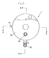
- Fig. 1 is a front view of an artificial lung according to a first embodiment of the present invention.
- Fig. 2 is a left side view of the artificial lung shown in Fig. 1.
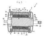
- Fig. 3 is a cross-sectional view along line A-A of Fig. 2.
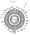
- Fig. 5 is a cross-sectional view along line C-C of Fig. 1.
- Fig. 6 is a cross-sectional view of an artificial lung according to a second embodiment of the present invention.
- one embodiment of the artificial lung 1 includes a tubular core 5, a tubular (cylindrical) hollow yarn film bundle 3 in which are accumulated a multiplicity of gas exchange hollow yarn films 3a, which are adapted to perform a gas exchange function, wound around the outer surface of the tubular core 5, a housing for containing the tubular hollow yarn film bundle 3 therein, a gas inflow portion and a gas outflow portion communicating with each other through the inside (lumen) of the hollow yarn films 3a, a blood inflow portion and a blood outflow portion for communication between the exterior of the hollow yarn films 3 and the inside of the housing, and a filter member 6 provided at the tubular hollow yarn film bundle 3.
- the tubular hollow yarn film bundle 3 has a structure in which hollow yarn film layers (hollow yarn films 3a) spread on the outer peripheral surface of the tubular core 5 are stacked in a multi-layer form, i.e., stacked or layered in a spiral form, or taken up into a reel form, with the tubular core as a core. Further, the hollow yarn film layers are so configured that an intersection portion 3b where the hollow yarn films 3a intersect each other is provided in the vicinity of the center in the longitudinal direction of the tubular core 5, with the intersection portions 3b being located at different positions so that one intersection portion 3b is not stacked directly on another intersection portion 3b, or a direct stacking of one intersection portion 3b and another intersection portion 3b does not occur.
- the artificial lung 1 includes the housing 2, an artificial lung unit contained in the housing 2, and a tubular heat exchanger unit contained in the artificial lung unit so that the artificial lung is a heat exchange functionincorporating artificial lung.
- the artificial lung 1 comprises: the artificial lung unit which includes the tubular core 5, the tubular hollow yarn film bundle 3 having a multiplicity of gas exchange hollow yarn films wound around the outside surface of the tubular core 5, and a filter member 6; the tubular heat exchanger unit contained in the tubular core 5; and the housing 2 containing the artificial lung unit and the tubular heat exchanger unit therein.
- the outwardly facing surface of the tubular core 5 is provided with a plurality of grooves 51 forming blood conduits between the outside surface of the tubular core 5 and the inside surface of the tubular hollow yarn film bundle 3.
- the tubular core 5 is also provided with a blood flow opening(s) 52 providing communication between a first blood chamber 11, formed between the tubular core 5 and the tubular heat exchanger unit, and the grooves 51.
- the artificial lung 1 has a blood inflow port (blood inflow portion) 24 communicating with the first blood chamber 11 (the inner peripheral portion side of the tubular hollow yarn film bundle 3) formed between the tubular core 5 and the tubular heat exchanger unit, and a blood outflow port (blood outflow portion) 25 communicating with a second blood chamber 12 (the outer peripheral portion side of the tubular hollow yarn film bundle 3) formed between the outside surface of the tubular hollow yarn films and the inside surface of the housing 2.
- the blood inflow port 24 is provided with an inflow opening portion 40 opening into the first blood chamber 11. This helps ensure that blood from the blood inflow port 24 flows assuredly into the first blood chamber 11.
- the blood in the first blood chamber 11 passes through a blood distribution opening(s) 52 and through an inner peripheral portion 15 of the tubular hollow yarn film bundle 3 into the inside 16 of the tubular hollow yarn film bundle 3.
- the blood which has flowed into the inside 16 of the tubular hollow yarn film bundle 3 flows via an outer peripheral portion 17 of the tubular hollow yarn film bundle 3 into the second blood chamber 12.
- the blood outflow port 25 is provided with an outflow opening portion 43 opening into the second blood chamber 12. This helps ensure that the blood in the second blood chamber 12 flows out to the blood outflow port 25 assuredly.
- the hollow yarn film bundle 3, the tubular core 5 having the grooves 51, the first blood chamber 11, a tubular heat exchanger 31, tubular heat exchanger deformation restraining portions 34, 35, and a tubular heating medium forming member 32 are arranged or formed concentrically in this order from the outside.
- the housing 2 includes the tubular housing body 21 having the blood outflow port 28; a first header 22 having a gas inflow port (gas inflow portion) 26, a heating medium inflow port 25 and a heating medium outflow port 29; and a second header 23 having a gas outflow port (gas outflow portion) 27 and an insertion port for the blood inflow port 24 provided in the tubular core 5.
- the first header 22 is provided at its inside surface with a heating medium chamber forming member connection portion 22a projecting in a tubular form, and a partition portion 22b bisecting or dividing the inside of the heating medium chamber forming member connection portion 22a.
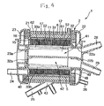
- the second header 23 is provided at its inside surface with a heating medium chamber forming member connection portion 32 projecting in a tubular form. As shown in Fig. 4, a tubular heating medium chamber forming member 32 described later has an opening end side held by the first header 22 and a closed end side held by the second header 23.
- the artificial lung unit includes the tubular core 5, the tubular hollow yarn film bundle 3 having a multiplicity of hollow yarn films wound around the outside surface of the tubular core 5, and the filter member 6 provided on the outer peripheral portion 17 of the tubular hollow yarn film bundle 3.
- the tubular core 5 is tubular in shape.
- An annular plate-like projecting portion 55 extending on the inside with a predetermined width is formed at one end of the tubular core 5, and the blood inflow port 24 is formed at the outside surface of a flat surface portion of the annular plate-like projecting portion 55 in parallel to the center axis of the tubular core 5 so as to project outwards.
- the outside surface of the tubular core 5 is provided with the multiplicity of grooves 51 forming blood conduits between the outside surface of the tubular core 5 and the inside surface of the tubular hollow yarn film bundle 3.
- the tubular core 5 also has the blood distribution opening(s) 52 providing communication between the grooves 51 and the first blood chamber 11 which is formed between the tubular core 5 and the tubular heat exchanger unit.
- the tubular core 5 possesses an outside diameter that is preferably about 20 to 100 mm, and an effective length (i.e.,. the length of the portion not buried in the partition wall) of preferably about 10 to 730 mm.
- the plurality of grooves 51 of the tubular core 5 are parallel to one another, but not continuous, and axially spaced apart over a range of the core exclusive of both end portions.
- the portions between the axially adjacent grooves 51 are provided as annular ribs 53.
- the grooves in the tubular core 5 are so formed as to be present over substantially the whole area of that portion of the hollow yarn film bundle which contributes to gas exchange (the effective length, or the portion not buried in the partition wall).
- the tubular core 5 used here has a non-grooved portion 54 (of a generally flat surface form) which is located substantially on an extension line of the blood inflow port 24 and extends substantially over the entirety of the grooved portion of the tubular core 5. Therefore, the grooves 51 and the ribs 53 of the tubular core 5 are formed as annular grooves 51 (arcuate grooves and annular ribs 53 (arcuate ribs) having starting ends and finishing ends (i.e., the grooves and ribs are not continuous).
- the non-grooved portion 54 of the core 5 extends substantially over the whole part (i.e., axial extent) of the grooved portion of the tubular core 5, whereby shape stability of the tubular hollow yarn film bundle 3 provided at the outside surface of the tubular core 5 is enhanced.
- non-grooved portion 54 is not indispensable, as the grooves 51 and the ribs 53 of the tubular core 5 may be endless fully annular grooves 51 and endless fully annular ribs 53, respectively.
- the tubular core 5 is provided with the grooves 51 over substantially the entire range of the effective length (the portion not buried in the partition wall) of the hollow yarn film bundle 3 so that it is possible to disperse the blood to substantially the whole part of the hollow yarn film bundle 3, thus effectively utilizing substantially the whole part of the hollow yarn films and achieving a relatively high gas exchange performance.
- each of the ribs 53 formed between the grooves 51 of the tubular core 5 is preferably a generally flat surface, meaning that the top of each of the ribs is not pointed.
- each of the ribs 53 is a shape that narrows toward the top of the rib (i.e., in a direction toward the hollow yarn film bundle 3.
- the ribs may thus possess a somewhat trapezoidal shape in cross-section). This helps ensure that the grooves 51 (blood conduits) are each broadened toward the inside surface of the hollow yarn film bundle so that the blood flows into the hollow yarn film bundle favorably.
- the blood inflow port 24 is provided on the side of one end portion of the tubular core 5, and the blood distribution opening(s) 52 is formed in a region opposed to a region obtained by extending the center line of the blood inflow port 24. This helps provide a relatively uniform blood distribution in the first blood chamber 11 formed between the tubular core 5 and the tubular heat exchanger unit, and can also enhance the heat exchange efficiency.
- the non-grooved portion 54 is circumferentially located substantially on the extension line of the blood inflow port 24 (i.e., the axis or center line of the blood inflow port 24 circumferentially coincides with the location of the non-grooved portions 54) and extends over substantially the entire axial extent of the grooved portion.
- the non-grooved portion 54 is a thinner portion (i.e., thinner in the radial direction) enabled by the absence of the grooves, whereby a blood guide portion 56 circumferentially located substantially on the extension line of the blood inflow port 24 (on the axial extension of the center line of the blood inflow port 24) is formed in the inside of the tubular core 5.
- the blood guide portion 56 is larger in inside diameter than the grooved portions. With the blood guide portion 56 thus provided, it is possible to cause the blood to relatively reliably flow into the whole part in the axial direction of the first blood chamber 11 formed between the tubular core and the tubular heat exchanger unit.
- a plurality of blood distribution openings 52 are provided in the tubular core 5 and are individually communicated with the plurality of annular grooves 51.
- the blood distribution openings 52 are circumferentially located in a region or location that is opposed (diametrically opposed) to the non-grooved portion 54 (blood guide portion 56).
- One of the ribs 53 is present between the adjacent openings 52.
- the hollow yarn film bundle 3 is wound around the outside surface of the tubular core 5.
- the hollow yarn films 3a forming the hollow yarn film bundle 3 are sequentially wound around the tubular core 5, as shown in Fig. 1, whereby the hollow yarn film layers spread on the outer peripheral surface of the tubular core 5 are stacked in a multi-layer form, i.e., stacked in a spiral form or taken up into a reel form with the tubular core 5 as a core.
- the hollow yarn film bundle 3 is formed by winding the hollow yarn film around the tubular core 5, fixing both ends of the hollow yarn film to the tubular housing body 21 by partition walls 8, 9, and cutting both ends of the hollow yarn film bundle 3. Both ends of the tubular core 5 with the hollow yarn film bundle 3 wound around the outside surface thereof are fixed in a liquid-tight manner to both end portions of the tubular housing body 21 by the partition walls 8, 9, and the second blood chamber 12 as an annular space (tubular space) is located between the outside surface of the tubular hollow yarn films and the inside surface of the tubular housing body 21.
- the partition walls 8, 9 are each preferably formed of a potting agent such as polyurethane and silicone rubber.
- a porous gas exchange film is used as the hollow yarn film.
- the porous hollow yarn film there can be used one which has an inside diameter of 100 to 1000 ⁇ m, a material thickness of 5 to 200 ⁇ m, preferably 10 to 100 ⁇ m, a porosity of 20% to 80%, preferably 30% to 60%, and a pore diameter of 0.01 to 5 ⁇ m, preferably 0.01 to 1 ⁇ m.
- a hydrophobic polymeric material such as polypropylene, polyethylene, polysulfone, polyacrynonitrile, polytetrafluoroethylene, cellulose acetate, etc. is used.
- polyolefin resin is a preferred material
- polypropylene is particularly preferred. It is more preferable to use a material whose wall is provided with micro-pores by an orientation method or a solid-liquid phase separation method.
- the outside diameter (overall size) of the hollow yarn film bundle 3 is preferably 30 to 162 mm, and the thickness of the hollow yarn film bundle 3 is preferably 3 to 28 mm.
- a filter member 6 is provided on the outer peripheral portion 17 of the tubular hollow yarn film bundle 3.
- the filter member 6 has the function of trapping bubbles present in the blood flowing into the artificial lung 1 (tubular hollow yarn film bundle 3).
- the filter member 6 is cylindrical in overall shape. With the filter member 6 having such a shape, the inner peripheral portion (inner peripheral surface) 61 if the filter member 6 is in contact with the outer peripheral portion (outer peripheral surface) 17 of the tubular hollow yarn film bundle 3. In addition, the filter member 6 is provided so as to cover substantially the whole part of the outer peripheral portion 17 of the tubular hollow yarn film 3.
- the filter member 6 With the filter member 6 thus provided, it is possible to enlarge the area of the filter member 6 (inner peripheral portion 61) and, therefore, to trap the bubbles more assuredly. In addition, the large area of the filter member 6 makes it possible to restrain or prevent the blood flow from being blocked, even upon generation of clogging (for example, with a coagulated lump of blood) at a part of the filter member 6.
- the second blood chamber 12 in the form of an annular gap is located between the filter member 6 and the housing 2. This makes it possible to prevent the filter member 6 from making contact with the inner peripheral surface of the housing 2, and to enable the blood flowing out from the outer peripheral portion 62 of the filter member 6 to pass through the inside of the second blood chamber 12 and, therefore, reach (flow into) the blood outflow port 25 relatively assuredly.
- the filter member 6 is preferably hydrophilic. Specifically, it is preferable that the filter member 6 itself is formed of a hydrophilic material or the surface of the filter member 6 is subjected to a hydrophilicity-imparting treatment (for example, plasma treatment or the like). This helps ensure that the removal of bubbles at the time of priming is easy to carry out, whereby it is more difficult for the bubbles to pass when the blood with the bubbles mixed therein passes, and outflow of the bubbles from the filter member 6 can be restrained effectively.
- a hydrophilicity-imparting treatment for example, plasma treatment or the like
- the material constituting the filter member 6 is not particularly limited.
- a mesh-like material (screen filter) is preferable as the constituent material. This makes it possible to trap the bubbles more assuredly and to allow the blood to pass through the filter member 6 relatively easily.
- the size of the openings of the filter member 6 are not particularly limited, although the openings are preferably not more than 50 ⁇ m, more preferably in the range of 20 to 45 ⁇ m. This helps promote a relatively reliable trapping of the bubbles.
- the filter member 6 configured as above contributes to achieving relatively reliable trapping of the bubbles present in the blood flowing from the first blood chamber 11 into the tubular hollow yarn film bundle 3, so that the bubbles can be relatively securely prevented from flowing out via the blood outflow port 25.
- the bubbles trapped by the filter member 6 enter (flow) into the multiplicity of pores formed in the outside surface of the hollow yarn films 3a (tubular hollow yarn film bundle 3) as the pressure at the blood side is higher than inside the lumens of the hollow yarn film bundle.
- the bubbles are thus discharged (flow out) from the gas outflow port 27 after passing through the lumens of the hollow yarn films 3a.
- the filter member 6 need not necessarily be so provided as to cover substantially the whole part of the outer peripheral portion 17 of the tubular hollow yarn film bundle 3.
- the filter member 6 may be so provided as to cover a part of the outer peripheral portion 17 of the tubular hollow yarn film bundle 3.
- a heat exchanger unit is contained in the inside of the tubular core 5 of the artificial lung unit formed as mentioned above.
- Various features pertaining to the heat exchanger unit will now be described.
- the annular first blood chamber 11 is formed between the tubular core 5 and the tubular heat exchanger unit, and the blood inflow port 24 communicates with this blood chamber 11.
- the tubular heat exchanger unit includes a tubular heat exchange body 31, a tubular heating medium chamber forming member 32 contained in the heat exchange body 31, and two tubular heat exchange body deformation restraining portions 34, 35 inserted between the tubular heat exchange body 31 and the tubular heating medium chamber forming member 32.
- the bellows type heat exchange body 31 (bellows pipe) includes a bellows forming portion having a multiplicity of hollow annular projections formed substantially parallel to a central side surface thereof, and cylindrical portions formed at both ends of the bellows forming portion and having an inside diameter approximately equal to that of the bellows forming portion.
- One of the cylindrical portions of the heat exchange body 31 is clamped between the inside surface of a side end portion of the blood inflow port 24 of the hollow tubular core 5 and a second header 23, and the other of the cylindrical portions of the heat exchange body 31 is clamped between the first header 22 and a tubular heat exchange body fixing member 49, which is inserted between a ring-like heat exchange body fixing member 48 inserted in one end of the hollow tubular core 5 and the first header 22.
- the bellows type heat exchange body 31 is formed in a so-called minute bellows-like form, from a metal such as stainless steel, aluminum, etc. or a resin material such as polyethylene, polycarbonate, etc. A metal such as stainless steel and aluminum is preferably used, from the viewpoint of strength and heat exchange efficiency.
- the bellows type heat exchange body 31 is composed of a bellows pipe assuming a wavy shape obtained by repetition of a multiplicity of recesses and projections substantially orthogonal to the axial direction (center axis) of the tubular heat exchange body 31.
- the tubular heating medium chamber forming member 32 is a tubular body opened at one end (on the side of the first header 22), and includes a partition wall 32a for partitioning the inside into an inflow side heating medium chamber 41 and an outflow side heating medium chamber 42, a first opening 33a communicated with the inflow side heating medium chamber 41 and extending in the axial direction, a second opening 33b communicated with the outflow side heat exchange chamber 42 and extending in the axial direction, and projections 36a and 36b.
- projections 36a, 36b are diametrically opposed to each other, are formed on the side surfaces at positions deviated by about 90° from the first opening 33a and the second opening 33b, project radially outwardly, and extend in the axial direction.
- the projection 36a enters into a groove formed at the center of the inside surface of the heat exchange body deformation restraining portion 34 and extends in the axial direction to thereby restrain the heat exchange body deformation restraining portion 34 from being moved.
- the projection 36b enters into a groove formed at the center of the inside surface of the heat exchange body deformation restraining portion 35 and extends in the axial direction, to thereby restrain the heat exchange body deformation restraining portion 35 from being moved.
- a partition portion 22b for bisecting the inside of the tubular connection portion 22a makes close contact with one surface (in this embodiment, the lower surface) of a tip end portion of the partition wall 32a of the tubular heating medium chamber forming member 32.
- the inflow side heating medium chamber 41 in the tubular heating medium chamber forming member 32 is communicated with the heating medium inflow port 28, and the outflow side heating medium chamber 42 is communicated with the heating medium outflow port 29.
- the two heat exchange body deformation restraining portions 34, 35 are provided at their abutting end portions with cutout portions extending in the axial direction.
- a medium inflow side passage 37 and a medium outflow side passage 38 are formed. It is to be understood that the two heat exchange body deformation restraining portions 34, 35 may be formed as one body.
- the heating medium flowing into the inside of the artificial lung 1 via the heating medium inflow port 28 passes through the inside of the first header 22 to flow into the inflow side heating medium chamber 41. Then, the heating medium passes through the inflow chamber side opening 33a of the tubular heating medium chamber forming member 32, passes through the medium inflow side passage 37 formed by the abutment portions of the heat exchange body deformation restraining portions 34, 35, and flows between the heat exchange body 31 and the heat exchange body deformation restraining portions 34, 35. In this instance, the heat exchange body 3 is warmed or cooled by the heating medium.
- the heating medium passes through the medium outflow side passage 38 formed by the abutment portions of the heat exchange body deformation restraining portions 34, 35, passes through the outflow chamber side opening 33b of the tubular heating medium chamber forming member 32, and flows out into the outflow side heating medium chamber 42 in the tubular heating medium chamber forming member 32. Subsequently, the heating medium passes through the inside of the first header 22 and flows out via the heating medium outflow port 29.
- the blood flowing into the artificial lung is distributed via the blood inflow port 24 and flows into the blood guide portion 56 constituting a part of the first blood chamber 11 formed between the tubular core 5 and the tubular heat exchanger unit.
- the blood flows between the tubular core 5 and the tubular heat exchange body, then passes through the openings 52 located at a position opposed to the first blood guide portion 56, and flows out of the tubular core 5.
- the blood makes contact with the hollow yarn films where gas exchange is performed, and then the blood flows into the second blood chamber 12 formed between the tubular housing body 21 and the outside surface of the hollow yarn films (the outside surface of the hollow yarn film bundle 3).
- the bubbles present in the blood are trapped by the filter member 6, as described above, and eventually enters into the lumens of the hollow yarn films 3a.
- the blood flowing into the second blood chamber 12 flows out of the artificial lung or is distributed via the blood outflow port 25.
- an oxygen-containing gas flowing in via the gas inflow port 26 passes through the inside of the first header 22, flows via the partition wall end face into the hollow yarn films, then passes through the inside of the second header 23, and flows out via the gas outflow port 27.
- Examples of the materials for forming the members other than the heat exchange body 31, i.e., the materials for forming the tubular housing body 21, the tubular core 5, the first and second headers 22, 23 and the like include polyolefins (e.g., polyethylene, polypropylene), ester resins (e.g., polyethylene terephthalate), styrene-based reins (e.g., polystyrene, MS resin, MBS resin), and polycarbonates.
- polyolefins e.g., polyethylene, polypropylene
- ester resins e.g., polyethylene terephthalate
- styrene-based reins e.g., polystyrene, MS resin, MBS resin
- the blood contact surfaces in the artificial lung 1 are preferably anti-thrombogenic surfaces.
- the anti-thrombogenic surfaces can be formed by covering the surfaces with an anti-thrombogenic material and fixing the material.
- the antithrombogenic material include heparin, urokinase, HEMA-St-HEMA copolymer, and poly-HEMA.
- Fig. 6 is a cross-sectional view of an artificial lung according to a second embodiment of the present invention.
- the following description of the second embodiment will focus primarily on the differences between this embodiment and the embodiment described above, with features in the second embodiment that correspond to those in the first embodiment being identified by the same reference numerals. A detailed discussion of features which have already been described will not be repeated in entirety.
- an outer peripheral portion 62 and an inner peripheral portion 61 of the filter member 6 are in contact with the outside layer 18 and the inside layer 19, respectively. Namely, the filter member 6 is clamped or situated between the outside layer 18 and the inside layer 19.
- the filter member 6 thus arranged makes it possible to relatively reliably trap the bubbles present in the blood flowing from the first blood chamber 11 into the tubular hollow yarn film bundle 3 and, hence, to securely prevent the bubbles from flowing out via the blood outflow port.
- one filter member 6 at an intermediate portion of the tubular hollow yarn film bundle 3 is not limitative.
- a plurality of filter members 6 may be provided.
Landscapes
- Health & Medical Sciences (AREA)
- Heart & Thoracic Surgery (AREA)
- Vascular Medicine (AREA)
- Hematology (AREA)
- Animal Behavior & Ethology (AREA)
- Engineering & Computer Science (AREA)
- Anesthesiology (AREA)
- Biomedical Technology (AREA)
- Emergency Medicine (AREA)
- Life Sciences & Earth Sciences (AREA)
- Urology & Nephrology (AREA)
- General Health & Medical Sciences (AREA)
- Public Health (AREA)
- Veterinary Medicine (AREA)
- Cardiology (AREA)
- External Artificial Organs (AREA)
- Separation Using Semi-Permeable Membranes (AREA)
- Prostheses (AREA)
Applications Claiming Priority (1)
| Application Number | Priority Date | Filing Date | Title |
|---|---|---|---|
| JP2004216448A JP4366268B2 (ja) | 2004-07-23 | 2004-07-23 | 人工肺 |
Publications (2)
| Publication Number | Publication Date |
|---|---|
| EP1618906A1 true EP1618906A1 (de) | 2006-01-25 |
| EP1618906B1 EP1618906B1 (de) | 2008-09-03 |
Family
ID=34937831
Family Applications (1)
| Application Number | Title | Priority Date | Filing Date |
|---|---|---|---|
| EP05015107A Active EP1618906B1 (de) | 2004-07-23 | 2005-07-12 | Künstliche Lunge |
Country Status (6)
| Country | Link |
|---|---|
| US (3) | US7431754B2 (de) |
| EP (1) | EP1618906B1 (de) |
| JP (1) | JP4366268B2 (de) |
| AT (1) | ATE406924T1 (de) |
| DE (1) | DE602005009441D1 (de) |
| ES (1) | ES2308345T3 (de) |
Cited By (12)
| Publication number | Priority date | Publication date | Assignee | Title |
|---|---|---|---|---|
| EP1810705A1 (de) * | 2006-01-19 | 2007-07-25 | Terumo Kabushiki Kaisha | Oxygenator |
| EP1810704A2 (de) | 2006-01-19 | 2007-07-25 | Terumo Kabushiki Kaisha | Oxygenator |
| EP1834656A1 (de) * | 2006-03-17 | 2007-09-19 | Eurosets S.r.l. | Integrierte Vorrichtung zum Erwärmen und Anreichern mit Sauerstoff von Blut in einem extrakorporalen Kreislauf |
| EP1839691A1 (de) * | 2006-03-28 | 2007-10-03 | Terumo Kabushiki Kaisha | Filterelement und seine Kombination mit einem Oxygenator |
| US7431754B2 (en) | 2004-07-23 | 2008-10-07 | Terumo Kabushiki Kaisha | Artificial lung |
| CN103458938A (zh) * | 2011-03-31 | 2013-12-18 | 泰尔茂株式会社 | 人工肺及体外循环装置 |
| WO2015128886A1 (en) * | 2014-02-28 | 2015-09-03 | Sorin Group Italia S.R.L. | System for providing an integrated arterial filter into an oxygenator, minimizing added priming volume |
| WO2015107486A3 (en) * | 2014-01-20 | 2015-11-12 | Eurosets S.R.L. | Device for the extracorporeal oxygenation of the blood of a patient |
| EP3263151A4 (de) * | 2015-02-24 | 2018-10-17 | Terumo Kabushiki Kaisha | Verfahren zur herstellung einer hohlfaserartigen blutverarbeitungsvorrichtung sowie hohlfaserartige blutverarbeitungsvorrichtung |
| US10322223B2 (en) | 2014-04-11 | 2019-06-18 | Medos Medizintechnik Ag | Oxygenator comprising a hollow-fiber film bundle |
| US11160912B2 (en) | 2010-08-19 | 2021-11-02 | Sorin Group Italia S.R.L. | Blood processing unit with modified flow path |
| WO2022217659A1 (zh) * | 2021-04-15 | 2022-10-20 | 上海超高环保科技股份有限公司 | 超高分子人工肺制作方法 |
Families Citing this family (19)
| Publication number | Priority date | Publication date | Assignee | Title |
|---|---|---|---|---|
| CN103381277B (zh) | 2005-04-21 | 2015-11-25 | 联邦高等教育系统匹兹堡大学 | 体外辅助呼吸器 |
| US8545754B2 (en) | 2009-04-23 | 2013-10-01 | Medtronic, Inc. | Radial design oxygenator with heat exchanger |
| WO2010125037A1 (de) * | 2009-04-29 | 2010-11-04 | Basf Se | Rohrbündelwärmeüberträger und verfahren zur entfernung von flüchtigen stoffen aus einer polymerlösung |
| JP5809438B2 (ja) * | 2010-04-29 | 2015-11-10 | ソリン・グループ・イタリア・ソシエタ・ア・レスポンサビリタ・リミタータ | 一体化された動脈フィルタを有する酸素付加器 |
| EP2692370B1 (de) | 2011-03-31 | 2018-08-22 | Terumo Kabushiki Kaisha | Künstliche lunge |
| US8865067B2 (en) * | 2011-04-29 | 2014-10-21 | Medtronic, Inc. | Combination oxygenator and arterial filter device for treating blood in an extracorporeal blood circuit |
| US8685319B2 (en) * | 2011-04-29 | 2014-04-01 | Medtronic, Inc. | Combination oxygenator and arterial filter device with a fiber bundle of continuously wound hollow fibers for treating blood in an extracorporeal blood circuit |
| JP5922360B2 (ja) * | 2011-09-08 | 2016-05-24 | 泉工医科工業株式会社 | 血液酸素加装置 |
| US9072987B2 (en) * | 2013-03-15 | 2015-07-07 | Gas Technology Institute | Method and apparatus for desorption using a microporous membrane operated in wetted mode |
| WO2015104725A1 (en) | 2014-01-09 | 2015-07-16 | Sorin Group Italia S.R.L. | Blood processing unit with heat exchanger core for providing modified flow path |
| WO2016075514A1 (en) | 2014-11-12 | 2016-05-19 | Sorin Group Italia S.R.L. | Elastic protection tube for a hollow fibre blood processing apparatus |
| WO2016118114A1 (en) * | 2015-01-20 | 2016-07-28 | Mirzoyan Michael | Intracorporeal artificial lung |
| WO2016181189A1 (en) | 2015-05-12 | 2016-11-17 | Sorin Group Italia S.R.L. | Blood gas exchanger with restriction element or elements to reduce gas exchange |
| EP3392632B1 (de) | 2015-12-14 | 2022-10-12 | Terumo Kabushiki Kaisha | Abnehmbarer drucksensor und extrakorporale zirkulationsvorrichtung mit abnehmbarem drucksensor |
| CN105396187B (zh) * | 2015-12-29 | 2018-11-30 | 中国科学院苏州生物医学工程技术研究所 | 一种体外膜氧合器 |
| KR101892597B1 (ko) * | 2016-10-10 | 2018-08-28 | 김기정 | 인체에 삽입 가능한 인공 폐 |
| CN109224163B (zh) * | 2018-10-16 | 2019-06-21 | 广东工业大学 | 一种热交换层外置的中空纤维膜式氧合器 |
| WO2020158777A1 (ja) * | 2019-01-29 | 2020-08-06 | ニプロ株式会社 | 人工肺装置 |
| EP3919095A4 (de) * | 2019-01-29 | 2023-01-25 | Nipro Corporation | Künstliche lungenvorrichtung |
Citations (4)
| Publication number | Priority date | Publication date | Assignee | Title |
|---|---|---|---|---|
| WO1997016213A2 (en) * | 1995-10-31 | 1997-05-09 | Baxter International Inc. | Extracorporeal blood oxygenation system having integrated blood pump, heat exchanger and membrane oxygenator |
| WO2000006357A1 (en) * | 1998-07-28 | 2000-02-10 | Terumo Cardiovascular Systems Corporation | Potting of tubular bundles in housing |
| EP1108462A2 (de) * | 1999-12-15 | 2001-06-20 | Terumo Kabushiki Kaisha | Hohlfaseroxygenator |
| EP1180374A1 (de) * | 2000-08-08 | 2002-02-20 | DIDECO S.p.A. | Vorrichtung zur Sauerstoffanreicherung von Blut in einem extrakorporalen Kreislauf |
Family Cites Families (21)
| Publication number | Priority date | Publication date | Assignee | Title |
|---|---|---|---|---|
| US3807958A (en) * | 1972-06-05 | 1974-04-30 | Harvey Res Corp William | A bubble oxygenerator including a blood foam return exchanger device |
| US4183961A (en) * | 1976-02-03 | 1980-01-15 | Shiley Incorporated | Method of oxygenating blood |
| JPS5623960A (en) * | 1979-08-03 | 1981-03-06 | Nippon Medical Sapurai Kk | Artificial lung |
| EP0049461B1 (de) | 1980-10-06 | 1986-04-02 | DIDECO S.p.A. | Vorrichtung zur Sauerstoffanreicherung von Blut in einem Kreislauf ausserhalb des Körpers mit Wärmetauscher |
| US4620965A (en) * | 1982-09-22 | 1986-11-04 | Terumo Corporation | Hollow fiber-type artificial lung |
| US4690758A (en) | 1984-11-05 | 1987-09-01 | Baxter Travenol Laboratories, Inc. | Mass transfer device |
| JPH0342927Y2 (de) * | 1987-02-09 | 1991-09-09 | ||
| JPH01139073A (ja) * | 1987-08-22 | 1989-05-31 | Terumo Corp | 中空糸膜型人工肺 |
| JPS63267367A (ja) | 1988-04-05 | 1988-11-04 | Terumo Corp | 中空糸型人工肺 |
| EP0371173A1 (de) * | 1988-11-03 | 1990-06-06 | BAXTER INTERNATIONAL INC. (a Delaware corporation) | Integrale Vorrichtung zum Entschäumen, Sammeln und Erwärmen von Blut sowie zum Filtern eines Kardiotomiestromes |
| JP2554734B2 (ja) * | 1989-01-27 | 1996-11-13 | ディデコ・ソチエタ・ペル・アチオーニ | 体外血液回路用集積装置及びその安全装置 |
| JPH0798061B2 (ja) | 1989-02-13 | 1995-10-25 | 株式会社クラレ | 血液処理装置 |
| JP3051495B2 (ja) * | 1991-05-13 | 2000-06-12 | テルモ株式会社 | 除泡装置および貯血槽 |
| JPH07328114A (ja) | 1994-06-10 | 1995-12-19 | Koji Higuchi | 動脈フィルタを内蔵した酸素加装置 |
| JPH0819601A (ja) | 1994-07-08 | 1996-01-23 | Senko Ika Kogyo Kk | 人工肺 |
| JPH1147268A (ja) * | 1997-08-06 | 1999-02-23 | Terumo Corp | 中空糸膜型人工肺 |
| JPH11137671A (ja) | 1997-11-05 | 1999-05-25 | Terumo Corp | 熱交換器内蔵型人工肺 |
| US6730267B2 (en) * | 2001-02-09 | 2004-05-04 | Cardiovention, Inc. | Integrated blood handling system having active gas removal system and methods of use |
| ITMI20021552A1 (it) * | 2002-07-15 | 2004-01-15 | Dideco Spa | Dispositivo per il trattamento di sangue in circuito extracorporeo |
| US7022284B2 (en) * | 2003-05-09 | 2006-04-04 | Cardiovention, Inc. | Extracorporeal blood handling system with integrated heat exchanger |
| JP4366268B2 (ja) | 2004-07-23 | 2009-11-18 | テルモ株式会社 | 人工肺 |
-
2004
- 2004-07-23 JP JP2004216448A patent/JP4366268B2/ja not_active Expired - Lifetime
-
2005
- 2005-07-12 EP EP05015107A patent/EP1618906B1/de active Active
- 2005-07-12 AT AT05015107T patent/ATE406924T1/de not_active IP Right Cessation
- 2005-07-12 DE DE602005009441T patent/DE602005009441D1/de active Active
- 2005-07-12 ES ES05015107T patent/ES2308345T3/es active Active
- 2005-07-13 US US11/179,743 patent/US7431754B2/en active Active
-
2008
- 2008-09-08 US US12/206,440 patent/US7947113B2/en active Active
-
2011
- 2011-04-12 US US13/085,157 patent/US8142546B2/en active Active
Patent Citations (4)
| Publication number | Priority date | Publication date | Assignee | Title |
|---|---|---|---|---|
| WO1997016213A2 (en) * | 1995-10-31 | 1997-05-09 | Baxter International Inc. | Extracorporeal blood oxygenation system having integrated blood pump, heat exchanger and membrane oxygenator |
| WO2000006357A1 (en) * | 1998-07-28 | 2000-02-10 | Terumo Cardiovascular Systems Corporation | Potting of tubular bundles in housing |
| EP1108462A2 (de) * | 1999-12-15 | 2001-06-20 | Terumo Kabushiki Kaisha | Hohlfaseroxygenator |
| EP1180374A1 (de) * | 2000-08-08 | 2002-02-20 | DIDECO S.p.A. | Vorrichtung zur Sauerstoffanreicherung von Blut in einem extrakorporalen Kreislauf |
Cited By (33)
| Publication number | Priority date | Publication date | Assignee | Title |
|---|---|---|---|---|
| US8142546B2 (en) | 2004-07-23 | 2012-03-27 | Terumo Kabushiki Kaisha | Artificial lung |
| US7431754B2 (en) | 2004-07-23 | 2008-10-07 | Terumo Kabushiki Kaisha | Artificial lung |
| US7947113B2 (en) | 2004-07-23 | 2011-05-24 | Terumo Kabushiki Kaisha | Artificial lung |
| EP1810704A2 (de) | 2006-01-19 | 2007-07-25 | Terumo Kabushiki Kaisha | Oxygenator |
| EP1810705A1 (de) * | 2006-01-19 | 2007-07-25 | Terumo Kabushiki Kaisha | Oxygenator |
| US8968652B2 (en) | 2006-01-19 | 2015-03-03 | Terumo Kabushiki Kaisha | Oxygenator |
| US8017075B2 (en) | 2006-01-19 | 2011-09-13 | Terumo Kabushiki Kaisha | Oxygenator |
| EP1834656A1 (de) * | 2006-03-17 | 2007-09-19 | Eurosets S.r.l. | Integrierte Vorrichtung zum Erwärmen und Anreichern mit Sauerstoff von Blut in einem extrakorporalen Kreislauf |
| US8066942B2 (en) | 2006-03-17 | 2011-11-29 | Eurosets S.R.L. | Integrated device for heating and oxygenating blood in an extracorporeal circuit |
| US9199025B2 (en) | 2006-03-28 | 2015-12-01 | Terumo Kabushiki Kaisha | Filter member and oxygenator using same |
| EP1839691A1 (de) * | 2006-03-28 | 2007-10-03 | Terumo Kabushiki Kaisha | Filterelement und seine Kombination mit einem Oxygenator |
| US9522362B2 (en) | 2006-03-28 | 2016-12-20 | Terumo Kabushiki Kaisha | Filter member and oxygenator using same |
| US8425838B2 (en) | 2006-03-28 | 2013-04-23 | Terumo Kabushiki Kaisha | Filter member and oxygenator using same |
| US8911666B2 (en) | 2006-03-28 | 2014-12-16 | Terumo Kabushiki Kaisha | Filter member and oxygenator using same |
| EP2147691A1 (de) * | 2006-03-28 | 2010-01-27 | Terumo Kabushiki Kaisha | Oxygenator |
| US11160912B2 (en) | 2010-08-19 | 2021-11-02 | Sorin Group Italia S.R.L. | Blood processing unit with modified flow path |
| EP2692371A4 (de) * | 2011-03-31 | 2014-12-24 | Terumo Corp | Künstliche lunge und extrakorporaler kreislauf |
| EP2692371A1 (de) * | 2011-03-31 | 2014-02-05 | Terumo Kabushiki Kaisha | Künstliche lunge und extrakorporaler kreislauf |
| US9283311B2 (en) | 2011-03-31 | 2016-03-15 | Terumo Kabushiki Kaisha | Oxygenator and extracorporeal circuit |
| CN103458938B (zh) * | 2011-03-31 | 2016-06-01 | 泰尔茂株式会社 | 人工肺及体外循环装置 |
| CN103458938A (zh) * | 2011-03-31 | 2013-12-18 | 泰尔茂株式会社 | 人工肺及体外循环装置 |
| WO2015107486A3 (en) * | 2014-01-20 | 2015-11-12 | Eurosets S.R.L. | Device for the extracorporeal oxygenation of the blood of a patient |
| US10124105B2 (en) | 2014-01-20 | 2018-11-13 | Eurosets S.R.L. | Device for the extracorporeal oxygenation of the blood of a patient |
| CN106163584A (zh) * | 2014-01-20 | 2016-11-23 | 优罗塞斯有限责任公司 | 用于病人血液体外氧合的装置 |
| CN106163584B (zh) * | 2014-01-20 | 2019-03-19 | 优罗塞斯有限责任公司 | 用于病人血液体外氧合的装置 |
| WO2015128886A1 (en) * | 2014-02-28 | 2015-09-03 | Sorin Group Italia S.R.L. | System for providing an integrated arterial filter into an oxygenator, minimizing added priming volume |
| CN106029118B (zh) * | 2014-02-28 | 2018-10-02 | 索林集团意大利有限责任公司 | 用于将集成动脉过滤器设置在氧合器中、使增加的预充量最小化的系统 |
| US10369262B2 (en) | 2014-02-28 | 2019-08-06 | Sorin Group Italia S.R.L. | System for providing an integrated arterial filter into an oxygenator, minimizing added priming volume |
| CN106029118A (zh) * | 2014-02-28 | 2016-10-12 | 索林集团意大利有限责任公司 | 用于将集成动脉过滤器设置在氧合器中、使增加的预充量最小化的系统 |
| US11471577B2 (en) | 2014-02-28 | 2022-10-18 | Sorin Group S.r.l. | System for providing an integrated arterial filter into an oxygenator, minimizing added priming volume |
| US10322223B2 (en) | 2014-04-11 | 2019-06-18 | Medos Medizintechnik Ag | Oxygenator comprising a hollow-fiber film bundle |
| EP3263151A4 (de) * | 2015-02-24 | 2018-10-17 | Terumo Kabushiki Kaisha | Verfahren zur herstellung einer hohlfaserartigen blutverarbeitungsvorrichtung sowie hohlfaserartige blutverarbeitungsvorrichtung |
| WO2022217659A1 (zh) * | 2021-04-15 | 2022-10-20 | 上海超高环保科技股份有限公司 | 超高分子人工肺制作方法 |
Also Published As
| Publication number | Publication date |
|---|---|
| US7431754B2 (en) | 2008-10-07 |
| US20110186514A1 (en) | 2011-08-04 |
| ATE406924T1 (de) | 2008-09-15 |
| US20060016743A1 (en) | 2006-01-26 |
| US20090107898A1 (en) | 2009-04-30 |
| JP2006034466A (ja) | 2006-02-09 |
| ES2308345T3 (es) | 2008-12-01 |
| EP1618906B1 (de) | 2008-09-03 |
| JP4366268B2 (ja) | 2009-11-18 |
| US8142546B2 (en) | 2012-03-27 |
| US7947113B2 (en) | 2011-05-24 |
| DE602005009441D1 (de) | 2008-10-16 |
Similar Documents
| Publication | Publication Date | Title |
|---|---|---|
| US7431754B2 (en) | Artificial lung | |
| US6503451B2 (en) | Oxygenator of hollow fiber membrane type | |
| EP2335752B1 (de) | Oxygenator | |
| EP1810705B1 (de) | Oxygenator | |
| CN103458938A (zh) | 人工肺及体外循环装置 | |
| JP2007260151A (ja) | フィルタ部材および人工肺 | |
| JP6109150B2 (ja) | 医療器具 | |
| EP0895786A1 (de) | Hohlfasermembran-Oxygenator | |
| JP4892589B2 (ja) | 人工肺 | |
| JP4874088B2 (ja) | 人工肺 | |
| JP6364302B2 (ja) | 人工肺 | |
| JP2000093509A (ja) | 熱交換機能内蔵中空糸膜型人工肺 | |
| JP3936111B2 (ja) | 中空糸膜型人工肺 | |
| JP3936376B2 (ja) | 中空糸膜型人工肺 | |
| JP4533851B2 (ja) | 人工肺 | |
| JP2003010323A (ja) | 人工肺 |
Legal Events
| Date | Code | Title | Description |
|---|---|---|---|
| PUAI | Public reference made under article 153(3) epc to a published international application that has entered the european phase |
Free format text: ORIGINAL CODE: 0009012 |
|
| AK | Designated contracting states |
Kind code of ref document: A1 Designated state(s): AT BE BG CH CY CZ DE DK EE ES FI FR GB GR HU IE IS IT LI LT LU LV MC NL PL PT RO SE SI SK TR |
|
| AX | Request for extension of the european patent |
Extension state: AL BA HR MK YU |
|
| 17P | Request for examination filed |
Effective date: 20060602 |
|
| 17Q | First examination report despatched |
Effective date: 20060706 |
|
| AKX | Designation fees paid |
Designated state(s): AT BE BG CH CY CZ DE DK EE ES FI FR GB GR HU IE IS IT LI LT LU LV MC NL PL PT RO SE SI SK TR |
|
| 17Q | First examination report despatched |
Effective date: 20060706 |
|
| GRAP | Despatch of communication of intention to grant a patent |
Free format text: ORIGINAL CODE: EPIDOSNIGR1 |
|
| RIN1 | Information on inventor provided before grant (corrected) |
Inventor name: OGIHARA, MITSUAKI Inventor name: NAKAYAMA, HIDETAKA |
|
| GRAS | Grant fee paid |
Free format text: ORIGINAL CODE: EPIDOSNIGR3 |
|
| GRAA | (expected) grant |
Free format text: ORIGINAL CODE: 0009210 |
|
| AK | Designated contracting states |
Kind code of ref document: B1 Designated state(s): AT BE BG CH CY CZ DE DK EE ES FI FR GB GR HU IE IS IT LI LT LU LV MC NL PL PT RO SE SI SK TR |
|
| REG | Reference to a national code |
Ref country code: GB Ref legal event code: FG4D |
|
| REG | Reference to a national code |
Ref country code: CH Ref legal event code: EP |
|
| REG | Reference to a national code |
Ref country code: IE Ref legal event code: FG4D |
|
| REF | Corresponds to: |
Ref document number: 602005009441 Country of ref document: DE Date of ref document: 20081016 Kind code of ref document: P |
|
| REG | Reference to a national code |
Ref country code: SE Ref legal event code: TRGR |
|
| REG | Reference to a national code |
Ref country code: ES Ref legal event code: FG2A Ref document number: 2308345 Country of ref document: ES Kind code of ref document: T3 |
|
| PG25 | Lapsed in a contracting state [announced via postgrant information from national office to epo] |
Ref country code: LT Free format text: LAPSE BECAUSE OF FAILURE TO SUBMIT A TRANSLATION OF THE DESCRIPTION OR TO PAY THE FEE WITHIN THE PRESCRIBED TIME-LIMIT Effective date: 20080903 |
|
| PG25 | Lapsed in a contracting state [announced via postgrant information from national office to epo] |
Ref country code: SI Free format text: LAPSE BECAUSE OF FAILURE TO SUBMIT A TRANSLATION OF THE DESCRIPTION OR TO PAY THE FEE WITHIN THE PRESCRIBED TIME-LIMIT Effective date: 20080903 Ref country code: FI Free format text: LAPSE BECAUSE OF FAILURE TO SUBMIT A TRANSLATION OF THE DESCRIPTION OR TO PAY THE FEE WITHIN THE PRESCRIBED TIME-LIMIT Effective date: 20080903 Ref country code: LV Free format text: LAPSE BECAUSE OF FAILURE TO SUBMIT A TRANSLATION OF THE DESCRIPTION OR TO PAY THE FEE WITHIN THE PRESCRIBED TIME-LIMIT Effective date: 20080903 Ref country code: AT Free format text: LAPSE BECAUSE OF FAILURE TO SUBMIT A TRANSLATION OF THE DESCRIPTION OR TO PAY THE FEE WITHIN THE PRESCRIBED TIME-LIMIT Effective date: 20080903 |
|
| PG25 | Lapsed in a contracting state [announced via postgrant information from national office to epo] |
Ref country code: BE Free format text: LAPSE BECAUSE OF FAILURE TO SUBMIT A TRANSLATION OF THE DESCRIPTION OR TO PAY THE FEE WITHIN THE PRESCRIBED TIME-LIMIT Effective date: 20080903 |
|
| PG25 | Lapsed in a contracting state [announced via postgrant information from national office to epo] |
Ref country code: BG Free format text: LAPSE BECAUSE OF FAILURE TO SUBMIT A TRANSLATION OF THE DESCRIPTION OR TO PAY THE FEE WITHIN THE PRESCRIBED TIME-LIMIT Effective date: 20081203 |
|
| PG25 | Lapsed in a contracting state [announced via postgrant information from national office to epo] |
Ref country code: PT Free format text: LAPSE BECAUSE OF FAILURE TO SUBMIT A TRANSLATION OF THE DESCRIPTION OR TO PAY THE FEE WITHIN THE PRESCRIBED TIME-LIMIT Effective date: 20090203 Ref country code: CZ Free format text: LAPSE BECAUSE OF FAILURE TO SUBMIT A TRANSLATION OF THE DESCRIPTION OR TO PAY THE FEE WITHIN THE PRESCRIBED TIME-LIMIT Effective date: 20080903 Ref country code: IS Free format text: LAPSE BECAUSE OF FAILURE TO SUBMIT A TRANSLATION OF THE DESCRIPTION OR TO PAY THE FEE WITHIN THE PRESCRIBED TIME-LIMIT Effective date: 20090103 Ref country code: RO Free format text: LAPSE BECAUSE OF FAILURE TO SUBMIT A TRANSLATION OF THE DESCRIPTION OR TO PAY THE FEE WITHIN THE PRESCRIBED TIME-LIMIT Effective date: 20080903 Ref country code: SK Free format text: LAPSE BECAUSE OF FAILURE TO SUBMIT A TRANSLATION OF THE DESCRIPTION OR TO PAY THE FEE WITHIN THE PRESCRIBED TIME-LIMIT Effective date: 20080903 |
|
| PLBE | No opposition filed within time limit |
Free format text: ORIGINAL CODE: 0009261 |
|
| STAA | Information on the status of an ep patent application or granted ep patent |
Free format text: STATUS: NO OPPOSITION FILED WITHIN TIME LIMIT |
|
| PG25 | Lapsed in a contracting state [announced via postgrant information from national office to epo] |
Ref country code: EE Free format text: LAPSE BECAUSE OF FAILURE TO SUBMIT A TRANSLATION OF THE DESCRIPTION OR TO PAY THE FEE WITHIN THE PRESCRIBED TIME-LIMIT Effective date: 20080903 Ref country code: DK Free format text: LAPSE BECAUSE OF FAILURE TO SUBMIT A TRANSLATION OF THE DESCRIPTION OR TO PAY THE FEE WITHIN THE PRESCRIBED TIME-LIMIT Effective date: 20080903 |
|
| 26N | No opposition filed |
Effective date: 20090604 |
|
| PG25 | Lapsed in a contracting state [announced via postgrant information from national office to epo] |
Ref country code: MC Free format text: LAPSE BECAUSE OF NON-PAYMENT OF DUE FEES Effective date: 20090731 |
|
| REG | Reference to a national code |
Ref country code: CH Ref legal event code: PL |
|
| PG25 | Lapsed in a contracting state [announced via postgrant information from national office to epo] |
Ref country code: LI Free format text: LAPSE BECAUSE OF NON-PAYMENT OF DUE FEES Effective date: 20090731 Ref country code: CH Free format text: LAPSE BECAUSE OF NON-PAYMENT OF DUE FEES Effective date: 20090731 |
|
| PG25 | Lapsed in a contracting state [announced via postgrant information from national office to epo] |
Ref country code: PL Free format text: LAPSE BECAUSE OF FAILURE TO SUBMIT A TRANSLATION OF THE DESCRIPTION OR TO PAY THE FEE WITHIN THE PRESCRIBED TIME-LIMIT Effective date: 20080903 |
|
| PG25 | Lapsed in a contracting state [announced via postgrant information from national office to epo] |
Ref country code: IE Free format text: LAPSE BECAUSE OF NON-PAYMENT OF DUE FEES Effective date: 20090712 |
|
| PG25 | Lapsed in a contracting state [announced via postgrant information from national office to epo] |
Ref country code: GR Free format text: LAPSE BECAUSE OF FAILURE TO SUBMIT A TRANSLATION OF THE DESCRIPTION OR TO PAY THE FEE WITHIN THE PRESCRIBED TIME-LIMIT Effective date: 20081204 |
|
| PG25 | Lapsed in a contracting state [announced via postgrant information from national office to epo] |
Ref country code: LU Free format text: LAPSE BECAUSE OF NON-PAYMENT OF DUE FEES Effective date: 20090712 |
|
| PG25 | Lapsed in a contracting state [announced via postgrant information from national office to epo] |
Ref country code: HU Free format text: LAPSE BECAUSE OF FAILURE TO SUBMIT A TRANSLATION OF THE DESCRIPTION OR TO PAY THE FEE WITHIN THE PRESCRIBED TIME-LIMIT Effective date: 20090304 |
|
| PG25 | Lapsed in a contracting state [announced via postgrant information from national office to epo] |
Ref country code: TR Free format text: LAPSE BECAUSE OF FAILURE TO SUBMIT A TRANSLATION OF THE DESCRIPTION OR TO PAY THE FEE WITHIN THE PRESCRIBED TIME-LIMIT Effective date: 20080903 |
|
| PG25 | Lapsed in a contracting state [announced via postgrant information from national office to epo] |
Ref country code: CY Free format text: LAPSE BECAUSE OF FAILURE TO SUBMIT A TRANSLATION OF THE DESCRIPTION OR TO PAY THE FEE WITHIN THE PRESCRIBED TIME-LIMIT Effective date: 20080903 |
|
| REG | Reference to a national code |
Ref country code: FR Ref legal event code: PLFP Year of fee payment: 12 |
|
| REG | Reference to a national code |
Ref country code: FR Ref legal event code: PLFP Year of fee payment: 13 |
|
| REG | Reference to a national code |
Ref country code: FR Ref legal event code: PLFP Year of fee payment: 14 |
|
| PGFP | Annual fee paid to national office [announced via postgrant information from national office to epo] |
Ref country code: ES Payment date: 20180802 Year of fee payment: 14 |
|
| PGFP | Annual fee paid to national office [announced via postgrant information from national office to epo] |
Ref country code: SE Payment date: 20180710 Year of fee payment: 14 Ref country code: GB Payment date: 20180711 Year of fee payment: 14 |
|
| REG | Reference to a national code |
Ref country code: SE Ref legal event code: EUG |
|
| GBPC | Gb: european patent ceased through non-payment of renewal fee |
Effective date: 20190712 |
|
| PG25 | Lapsed in a contracting state [announced via postgrant information from national office to epo] |
Ref country code: SE Free format text: LAPSE BECAUSE OF NON-PAYMENT OF DUE FEES Effective date: 20190713 Ref country code: GB Free format text: LAPSE BECAUSE OF NON-PAYMENT OF DUE FEES Effective date: 20190712 |
|
| REG | Reference to a national code |
Ref country code: ES Ref legal event code: FD2A Effective date: 20201126 |
|
| PG25 | Lapsed in a contracting state [announced via postgrant information from national office to epo] |
Ref country code: ES Free format text: LAPSE BECAUSE OF NON-PAYMENT OF DUE FEES Effective date: 20190713 |
|
| PGFP | Annual fee paid to national office [announced via postgrant information from national office to epo] |
Ref country code: IT Payment date: 20230612 Year of fee payment: 19 |
|
| PGFP | Annual fee paid to national office [announced via postgrant information from national office to epo] |
Ref country code: DE Payment date: 20230531 Year of fee payment: 19 |
|
| PGFP | Annual fee paid to national office [announced via postgrant information from national office to epo] |
Ref country code: NL Payment date: 20240613 Year of fee payment: 20 |
|
| PGFP | Annual fee paid to national office [announced via postgrant information from national office to epo] |
Ref country code: FR Payment date: 20240611 Year of fee payment: 20 |