EP1617552B1 - Antriebssteuerungsvorrichtung und Verfahren eines Wechselstrommotors - Google Patents
Antriebssteuerungsvorrichtung und Verfahren eines Wechselstrommotors Download PDFInfo
- Publication number
- EP1617552B1 EP1617552B1 EP05015035A EP05015035A EP1617552B1 EP 1617552 B1 EP1617552 B1 EP 1617552B1 EP 05015035 A EP05015035 A EP 05015035A EP 05015035 A EP05015035 A EP 05015035A EP 1617552 B1 EP1617552 B1 EP 1617552B1
- Authority
- EP
- European Patent Office
- Prior art keywords
- estimated
- value
- voltage phase
- torque value
- voltage
- Prior art date
- Legal status (The legal status is an assumption and is not a legal conclusion. Google has not performed a legal analysis and makes no representation as to the accuracy of the status listed.)
- Ceased
Links
- 238000000034 method Methods 0.000 title claims description 25
- 238000004364 calculation method Methods 0.000 claims description 62
- 238000001514 detection method Methods 0.000 claims description 14
- 230000008569 process Effects 0.000 claims description 14
- 230000008859 change Effects 0.000 claims description 12
- 238000013178 mathematical model Methods 0.000 claims description 7
- 238000006243 chemical reaction Methods 0.000 claims description 5
- 230000010354 integration Effects 0.000 claims description 2
- 150000001875 compounds Chemical class 0.000 claims 1
- 230000004044 response Effects 0.000 description 16
- 238000001914 filtration Methods 0.000 description 12
- 238000010586 diagram Methods 0.000 description 11
- 230000000694 effects Effects 0.000 description 4
- 230000004907 flux Effects 0.000 description 4
- 230000001052 transient effect Effects 0.000 description 3
- 238000004458 analytical method Methods 0.000 description 2
- 230000008901 benefit Effects 0.000 description 2
- 230000000593 degrading effect Effects 0.000 description 2
- 238000005516 engineering process Methods 0.000 description 2
- 238000011156 evaluation Methods 0.000 description 2
- 238000004804 winding Methods 0.000 description 2
- 238000013459 approach Methods 0.000 description 1
- 230000002349 favourable effect Effects 0.000 description 1
- 230000002265 prevention Effects 0.000 description 1
Images


Classifications
-
- H—ELECTRICITY
- H02—GENERATION; CONVERSION OR DISTRIBUTION OF ELECTRIC POWER
- H02P—CONTROL OR REGULATION OF ELECTRIC MOTORS, ELECTRIC GENERATORS OR DYNAMO-ELECTRIC CONVERTERS; CONTROLLING TRANSFORMERS, REACTORS OR CHOKE COILS
- H02P21/00—Arrangements or methods for the control of electric machines by vector control, e.g. by control of field orientation
- H02P21/22—Current control, e.g. using a current control loop
Definitions
- the invention relates to a drive control apparatus and method for controlling an alternating current motor,hereinafterreferred to as an "AC motor", subjected to rotational drive by applying a rectangular wave voltage thereto.
- AC motor alternating current motor
- Japanese Patent Laid-Open Publication Nos. 2001-28892 and 2000-50689 respectively disclose a drive control apparatus which calculates such a voltage phase so as to eliminate deviation of an output torque value from a command torque value by feeding back an output torque value of a motor.
- Japanese Patent Laid-Open Publication No. 2001-28892 obtains an output torque value based on respective phase currents detected by a detector, a command voltage value, and an angular speed.
- Japanese Patent Laid-Open Publication No. 2000-50689 obtains an output torque value using a torque sensor.
- Japanese Patent Laid-Open Publication No. Hei 10-14273 discloses a control apparatus of a motor for controlling an inverter phase angle so that a command torque value may be outputted.
- This control apparatus obtains a torque compensation angle based on a deviation of an output torque value from a command torque value, and an angle (a voltage vector angle) to the flux axial direction of a voltage vector using a motor model with a motor in a simulated state and the command torque value.
- An inverter phase is calculated based on the obtained torque compensation angle and the voltage vector angle.
- a low pass filter for filtering out noise.
- noise filtering by the low pass filter is essential because the detected current value includes a harmonic component.
- use of the low pass filter causes a time lag in the obtained output torque value, thus degrading torque response.
- the drive control apparatuses disclosed in Japanese Patent Laid-Open Publication Nos. 2001-28892 and 2000-50689 which only feed back the output torque, have a disadvantage that the torque response of a motor is low.
- a control apparatus disclosed in the Japanese Patent Laid-Open Publication No. Hei 10-14273 makes combined use of feedback control and feed-forward control, which is capable of suppressing an effect of time lag in an output torque.
- the control apparatus disclosed in Japanese Patent Laid-Open Publication No. Hei 10-14273 calculates a voltage vector angle from a torque command. That is, it may be said that the voltage vector is a parameter with state quantity of a motor not considered. Therefore, there is a problem that a command torque value that changes in a stepped manner will also cause a voltage vector angle to change in a stepped manner, thus causing the output torque of the motor to have an overshoot state.
- conventional drive control of a motor has a disadvantage that low response or overshoot causes a control error, especially a significant control error in a transient region.
- the European Patent Application EP 1 263 125 A1 further discloses a drive control apparatus and method that drives an AC motor by applying a rectangular wave voltage thereto.
- the apparatus estimates the torque of a rotor of the AC motor, and detects a torque deviation which is the difference between the estimated torque and a required torque of the motor.
- a controller controls a state of the rectangular wave voltage applied to the AC motor, through torque feedback control based on the torque deviation, so that the torque approaches the torque command value.
- the controller detects a current rotation speed of the motor, and switches, in a predetermined order, a plurality of predetermined rectangular wave voltage states corresponding to different phase values of the rectangular wave voltage.
- the switching timing of the rectangular wave voltage states is set to a timing that deviates from a reference timing determined based on the current rotation speed, by a length of time corresponding to the torque deviation.
- the drive control apparatus of the present invention which controls an AC motor subjected to rotational drive by applying rectangular wave voltage thereto, comprises: actual torque detection means for detecting an actual torque value outputted from the AC motor; estimated torque calculation means for calculating an estimated torque value based on a motor model with the AC motor in a simulated state; and voltage phase calculation means for calculating a voltage phase based on the actual torque value, the estimated torque value and a predetermined command torque value, wherein the voltage phase calculation means adds an actual parameter based on the actual torque value calculated in the calculation process of the voltage phase to an estimated parameter based on the estimated torque value in a predetermined proportion, and calculates the voltage phase based on the obtained value.
- a drive control method controlling an AC motor subjected to rotational drive by applying rectangular wave voltage thereto, comprises: an actual torque detection process for detecting an actual torque value outputted from the AC motor; an estimated torque calculation process for calculating an estimated torque value based on a motor model with the AC motor in a simulated state; and a voltage phase calculation process for calculating a voltage phase of command voltage based on the actual torque value, the estimated torque value and a predetermined command torque value, especially a voltage phase calculation process for calculating a voltage phase based on a value obtained by adding an actual parameter based on an actual torque value calculated in a voltage phase calculation process of a voltage phase and an estimated parameter based on the estimated torque value in a predetermined proportion.
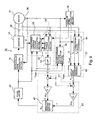
- Fig. 1 is a basic schematicblockdiagramof a drive control apparatus 10 for an AC motor 12 according to one embodiment of the present invention.
- the input-output relationship of each section shown in Fig. 1 is a typical example and may be a relationship other than the one illustrated.
- the drive control apparatus 10 controls the AC motor 12 driven by a rectangular wave voltage, and calculates a voltage phase ⁇ v corresponding to a predetermined command torque value T* and applies rectangular wave voltage to the AC motor 12.
- An inverter 14 is connected to the AC motor 12.
- the inverter 14 receives power supply from a power source, not shown, and passes current through stator windings for respective U, V and W phases of the AC motor 12.
- a current sensor 28 On a power supply line from the inverter 14 to the AC motor 12, there is provided a current sensor 28 to detect current values being supplied to the respective phase windings of the AC motor 12.
- the inverter 14 is connected with a rectangular wave generation section 16, which produces a SW signal of rectangular wave voltage for each phase, and the SW signal permits the inverter 14 to be subjected to switching control.
- the rectangular wave generation section 16 controls a phase of the SW signal based on a voltage phase ⁇ v obtained by a voltage phase calculation section 24 described below and a rotor angle ⁇ as an output from a resolver 26 provided next to the AC motor 12.
- An actual torque detection section 20 detects an actual torque value T as a torque value actually outputted from the motor. Detection of the actual torque value T can be performed in a wide variety of ways. As one of preferred way, an actual torque value T is calculated based on a current value detected by the current sensor 28. For example, supplied power is calculated by a product sum of a detected current and a command voltage value, and a value obtained by dividing the calculated power by an angular speed is taken as an actual torque T. As another method, magnetic torque and inductance torque are calculated from the detected current, and a sumof themmaybe taken as the actual torque value T. Moreover, as another embodiment, an output of a torque sensor attached onto the AC motor 12 may be taken as the actual torque value T.
- the actual torque detection section 20 filters out noise with a low pass filter in the detection process of the actual torque value T. This is because the value detected from the AC motor 12 includes noise. Especially, since the current value detected by the current sensor 28 includes a high-frequency component, the low pass filter is mandatory for calculation of the actual torque value T based on the detected current.
- the noise filtering-out may be applied directly to the detected current or to the actual torque value T calculated from the detected current.
- this embodiment uses an estimated torque calculation section 22 and a voltage phase calculation section 24 described below, thus achieving high response.
- the estimated torque calculation section 22 obtains an estimated torque value Tm of the AC motor 12.
- the estimated torque value Tm is calculated based on a motor model with the AC motor 12 in a simulated state.
- the motor model has a mathematical model obtained by approximating a current value supplied with a command voltage value, an inductance and an angular speed. By inputting the command voltage value, the inductance and the angular speed, an estimated current value supplied to the AC motor 12, hereinafter referred to an "estimated current value" can be calculated.
- the mathematical model for calculating the estimated current value is an observer constructed out of a Kalman filter in a preferred embodiment.
- an estimated current value Tm of the AC motor 12 is obtained.
- magnetic torque and inductance torque are calculated, a sum of which may be taken as the estimated torque value Tm.
- a command voltage value used to calculate the estimated current value and the estimated torque value is a value before it undergoes rectangular wave conversion. That is, the estimated current value and the estimated torque value are calculated with a value different from a voltage actually inputted into the AC motor 12.
- the inductance used to calculate the estimated current value and the estimated torque value may be a fixed value or a variable. Especially, for a motor generating magnetic flux saturation, use of the inductance varying with motor constant variation is preferable to reflect an inductance variation due to magnetic flux saturation on the estimated value.
- an instantaneous value or a fundamental wave component may be used as the command voltage value and the angular speed.
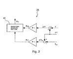
- Fig. 2 is a detail view of the voltage phase calculation section 24.
- the voltage phase calculation section 24 calculates such a voltage phase ⁇ v that the AC motor 12 can output a command torque value T*.
- a first voltage phase ⁇ fb of such a voltage phase as to eliminate a deviation ⁇ T between an actual torque value T and a command torque value T* is calculated.
- a second voltage phase ⁇ ff of such a voltage phase as to eliminate a deviation ⁇ T m between the estimated torque Tm and the command torque value T* is calculated.
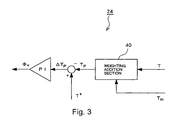
- a value obtained by weighting addition of the first voltage phase ⁇ fb and the second voltage phase ⁇ ff in a prescribed proportion is taken as a voltage phase ⁇ v.
- the first voltage phase ⁇ fb is the voltage phase obtained by feedback control. Use of only the voltage phase ⁇ fb cannot prevent generation of a time lag corresponding to a time constant of a low pass filter. Therefore, weighting addition of the second voltage phase ⁇ ff calculated from the estimated torque value without time lag improves torque response.
- the second voltage phase ⁇ ff is calculated from the estimated torque value and may be taken as a voltage phase with state quantity of the motor considered. Even if the command torque value T* changes in a stepped manner, the second voltage phase ⁇ ff changes continuously with the state quantity of the motor.
- the voltage phase ⁇ v from the weighting addition of the second voltage phase ⁇ ff and the first voltage phase ⁇ fb also changes continuously, thus preventing overshoot.
- the weighting addition of the first voltage phase ⁇ fb and the second voltage phase ⁇ ff improves response while preventing torque overshoot, thus suppressing a control error.
- the calculation methods of the first voltage phase ⁇ fb and the second voltage phase ⁇ ff may use various types of control technologies which have been conventionally proposed, such as technologies of P control, PI control and PID control.
- the proportion of the weighting addition may be a fixed value, but a variable is preferable which changes with an operating status such as a changing rate or magnitude of a command torque value. For example, it is desirable to take such a value as to obtain a higher proportion of the second voltage phase ⁇ ff as a change rate of a command torque value is higher.
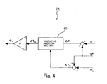
- the weighting addition may be made before the calculation of two types of voltage phases ⁇ ff, ⁇ fb.
- the voltage phase ⁇ v may be calculated based on a deviation ⁇ Tp of a torque value Tp after the calculation from a command torque value T*.
- the voltage phase ⁇ v may be calculated based on a deviation ⁇ Tp after the addition.
- phase limiter After the calculation of the voltage phase ⁇ v, a phase limiter may be provided.
- the phase limiter restricts the voltage phase ⁇ v to a predetermined range, for example, 90° to -90°. If the calculated voltage phase ⁇ v is in excess of 90°, it is clipped to 90°.
- Fig. 5 shows an example of a drive control apparatus.
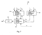
- an actual torque value T is calculated from three-phase supply currents (detected values) Iu, Iv, Iw, three-phase command voltage values Vuref, Vvref, Vwref and an angular speed ⁇ . Therefore, the three-phase current values Iu, Iv, Iw are inputted into an actual torque detection section 20 from a current sensor 28, and the angular speed ⁇ is inputted from an angular speed calculation section.
- the actual torque detection section 20 is provided with a three-phase command voltage calculation section 30, and the three-phase command voltage values Vuref, Vvref, Vwref are calculated from a battery voltage Vbatt and a voltage phase ⁇ v (a value on q-axis taken as 0°).
- the three-phase command voltage values Vuref, Vvref, Vwref can be calculated from the following equation (1).
- Vuref - ⁇ ⁇ 6 / ⁇ ⁇ Vbatt ⁇ sin ⁇ + ⁇ v
- Vvref - ⁇ ⁇ 6 / ⁇ ⁇ Vbatt ⁇ sin ⁇ + ⁇ v - 2 ⁇ ⁇ / 3
- Vwref - ⁇ ⁇ 6 / ⁇ ⁇ Vbatt ⁇ sin ⁇ + ⁇ v + 2 ⁇ ⁇ / 3
- the calculated three-phase command voltage values Vuref, Vvref, Vwref are inputted into the actual torque calculation section 32.
- the actual torque calculation section 32 calculates an actual torque value by dividing a product sum (a power value) of the three-phase command voltage values Vuref, Vvref, Vwref and three-phase supply current values Iu, Iv, Iw by an angular speed ⁇ .
- the calculated actual torque value T is inputted into the voltage phase calculation section 24 after the low pass filter 34 filters out noise.
- An estimated torque value Tm is calculated based on the motor model. Specifically, dq-axis estimated current values Idsim, Iqsim are calculated based on the mathematical model shown in the expression (3), and are substituted into the following equation (4) to calculate the estimated torque value Tm.
- dq-axis inductances Ld and Lq use values that vary according to motor constant variation. That is, a previous magnetic field analysis is made for the motor, and the dq-axis current value obtained from the magnetic field analysis result and a value obtained with an inductance map are used. This can reduce errors in the estimated current values even if an inductance variation occurs due to magnetic flux saturation or the like.
- Vdref ⁇ ⁇ 6 / ⁇ ⁇ Vbatt ⁇ sin ⁇ v
- Vqref ⁇ ⁇ 6 / ⁇ ⁇ Vbatt ⁇ cos ⁇ v
- the calculated estimated torque value Tm is inputted into the voltage phase calculation section 24 together with an actual torque value T and a command torque value T*.
- the command torque value T* is a torque target produced by an electronic control device, not shown.
- the voltage phase calculation section 24 calculates a deviation ⁇ T between an actual torque value T and a command torque value T* to calculate a first voltage phase ⁇ fb eliminating the deviation ⁇ T. Based on a deviation ⁇ Tm between the estimated torque value Tm and the command torque value T*, in the same way, a second voltage phase ⁇ ff eliminating the deviation ⁇ Tm is calculated. Both of the first voltage phase ⁇ fb and the second voltage phase ⁇ ff are calculated from the equations (6) and (7) by means of PI (proportional integration) control.
- PI proportional integration
- Kpfb and Kpff are proportional gains
- Kifb and Kiff are integral gains.
- the obtained first voltage phase ⁇ fb and the second voltage phase ⁇ ff are subjected to weighting addition in a predetermined proportion by the weighting addition section 40.
- a value obtained by the addition is a voltage phase ⁇ v of command voltage.
- the proportion of ⁇ to ⁇ is changed so that the proportion ( ⁇ ) of the second voltage phase ⁇ ff becomes higher as a change rate dT of the command torque value T* is higher.
- the proportion of the first voltage phase ⁇ fb is lowered in such a region that the change rate dT is high and high response is requested.
- the proportion of the first voltage phase ⁇ fb is increased in such a region that the change rate dT is low and no high response is requested.
- ⁇ (a proportion of the second voltage phase ⁇ ff) is increased in proportion to the magnitude of a change rate dT of a command torque value T*.
- an upper-limit threshold dTmax and a lower-limit threshold dTmin are provided. If the change rate dT exceeds the upper-limit threshold dTmax, ⁇ (a proportion of a first voltage phase ⁇ fb) is set to zero, and if the change rate dT is below the lower-limit threshold dTmin, ⁇ (a proportion of a second voltage phase ⁇ ff) is set to zero.
- FIG. 6 is a schematic block diagram illustrating another configuration of a weighting addition section 40.
- This addition method is established so that the proportion of the second voltage phase ⁇ ff may become higher as the change rate dT of the command torque value T* is higher, in other words, a frequency of the command torque value T* is higher.
- a low pass filter 54 to a first voltage phase ⁇ fb
- a high pass filter 52 to a second voltage phase ⁇ ff
- its output is added. If the frequency of the command torque value T* is high (in the case of a high change rate dT), frequencies of two voltage phases ⁇ ff, ⁇ fb become higher.
- the second voltage phase ⁇ ff can pass through the high pass filter 52, while the first voltage phase ⁇ fb is cut almost entirely by the low pass filter 54.
- the proportion of the second voltage phase ⁇ fb is increased if the frequency of the command torque value T* is high.
- the proportion of the first voltage phase ⁇ fb can be increased.
- the rectangular wave generation part 16 produces a SW signal of the inverter 14 based on a voltage phase ⁇ v and a rotor angle ⁇ described above.
- An output voltage from the inverter 14 as shown in the following equation (10) is applied to the motor 12 to drive the rotation of the AC motor 12.
- this embodiment provides a voltage phase ⁇ v with further reduced control errors by weighting addition of a first voltage phase ⁇ fb obtained from an actual torque value and a second voltage phase ⁇ ff obtained from an estimated torque value.
- This embodiment provides, especially a high torque response in a transient region and prevention of overshoot.
- the estimated torque value T may be calculated from the following equation (11) in place of the equation (4).
- Tm p ⁇ ⁇ ⁇ Iqsim + p ⁇ Ld - Lq Idsim ⁇ Iqsim where p is number of poles and ⁇ is an exciting constant.
- the p ⁇ Iqsim at the first term on the right side refers to a magnetic torque
- p(Ld-Lq) Idsim-Iqsim refers to a torque produced by an inductance.
- This embodiment uses a three-phase current value as a current value used to calculate an actual torque value T and a three-phase command voltage value, but may naturally use a dq-axis current value and a dq-axis command voltage value.
- a three-phase/ dq-axis conversion section 48 and a dq-axis command voltage calculation section 50 are provided for the actual torque detection section 20, and a current value and a voltage value converted on a dq-axis are inputted into the actual torque calculation section 32.
- the low pass filter may be applied to a current value detected as shown in Fig. 8 .
- FIG. 9 is a schematic block diagram illustrating a configuration according to another embodiment.
- configurations except those of the estimated torque calculation section 22 are the same as in the foregoing embodiment, and therefore its explanation is omitted.
- the estimated current values Idsim and Iqsim are calculated with an observer constructed out of a Kalman filter.
- the Kalman filter is an algorithm for improving estimated accuracy by sequentially evaluating an error between a measured value and an estimated value. Therefore, in estimating current values Id and Iq with the observer constructed outoftheKalmanfilter, detected current values Iu, Iv, Iw detected by the current sensor 28 are inputted into the motor model 38.
- the detected current values Iu, Iv and Iw are three-phase current values, and therefore a three-phase/ dq-axis conversion section 44 is provided for the estimated torque calculation section 22, and values obtained by converting the three-phase current values into dq-axis current values are inputted into the motor model.
- the equation (11) has terms for evaluating an error between the estimated values Idsi, and Iqsim and the detected values Id and Iq on the third and fourth terms on the right side. TAn estimated error is therefore sequentially modified. Thus, the estimated current value and the estimated torque value can be estimated more rapidly.
- the timings for inputting the detected current values Id and Iq into the observer are either before or after noise filtering, but the value at noise filtering can reduce estimated convergence time.
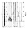
- FIG. 10 shows, in the order from the above, an actual torque value (before noise filtering), an estimated torque value calculated with a standard motor model (equations (3) and (4)), an estimated torque value (use of a detected current value before noise filtering) calculated with the motor model (equations (12) and (4)), through the use of the observer and estimated torque value (use of a detected current value after noise filtering) calculated with the motor model (equations (12) and (4)) through the use of the observer.
- a standard motor model (a graph at the second stage) requires approx. 130 msec. until an estimated value converges.
- an estimated value converges at approx. 10 msec.
- use of the observer can reduce estimated convergence time significantly compared to the standard motor model.
- control with few control errors can be achieved with higher rapidity.
- Use of a value after noise filtering as a detected value for estimated error evaluation can reduce control errors more significantly.
- the drive control apparatus 10 does not detect the actual torque value T, but calculates the voltage phase ⁇ v applied to the AC motor 12 based on the estimated torque value Tm and the predetermined command torque value T*.
- the estimated torque value Tm is calculated by the estimated torque calculation section 22.
- the estimated torque calculation section 22 has almost the same configuration to that of the estimated torque calculation section of the drive control apparatus shown in Fig. 5 , and includes a dq-axis command voltage calculation section 36 and the motor model 38.
- a battery voltage Vbatt and the voltage phase ⁇ v are inputted into the dq-axis command voltage calculation section 36. Both these parameters are substituted into an equation (5) to calculate dq-axis command voltage values Vdref and Vqref.
- the calculated voltage command values are inputted into the motor model 38.
- the battery voltage Vbatt is a voltage before rectangular wave conversion and a sine wave voltage.
- the motor model 38 is a mathematical model that approximates the output torque of the motor 12 with an angular speed ⁇ , a voltage command value and a current value. Specifically, it is a mathematical model shown in an equation (4).
- the angular speed ⁇ required to calculate the estimated torque value Tm is calculated by an angular speed calculation section 18 and inputted.
- the dq-axis command voltage values Vdref, Vqref calculated by the dq-axiscommand voltage calculation section 36 are substituted.
- dq-axis estimated current values Idsim, Iqsim calculated from the equation (3) are substituted.
- a difference from the command torque value T* is taken.
- the obtained difference ⁇ T is inputted into a PI control system to calculate the voltage phase ⁇ v.
- the voltage phase ⁇ v is calculated from the equation (7).
- the calculated voltage phase ⁇ v is inputted into a phase limiter 42 and, as necessary, is inputted into a rectangular wave generation section 16 after clipping.
- the rectangular wave generation part 16 produces a SW signal of an inverter 14.
- the inverter 14 produces a rectangular wave voltage by a switching operation based on the SW signal and applies the voltage to the AC motor 12.
- the estimated torque value Tm is calculated based on the motor model 38 in this way, and a voltage phase ⁇ v is calculated based on the estimated torque value Tm, thus enabling motor control with high response. Especially, if a variation in the command torque value T* is large, the drive control apparatus 10 according to this embodiment can rapidly follow the variation, thus reducing control errors.
- the dq-axis command voltage values Vdref and Vqref are calculated based on a battery voltage Vbatt as a sine wave voltage.
- the dq-axis command voltage values Vdref and Vqref are calculated based on a sine wave voltage.
- the sine wave voltage By using the sine wave voltage in this way, a favorable estimated torque value Tm without ripples can be obtained.
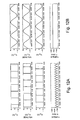
- FigS. 12A and 12B the estimated torque results are described below.
- Fig. 12A is a graph showing estimated torque results when rectangular wave voltages are inputted into an estimated torque calculation section.
- Fig. 12B is a graph showing estimated torque results when sine wave voltages are inputted into an estimated torque calculation section.
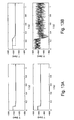
- Fig. 13A is a graph showing results when a motor is controlled with sine wave voltages.
- Fig. 13B is a graph showing results when a motor is controlled with rectangular wave voltages.
- Each figure shows, at its lower stage, the result obtained by applying the estimated torque value calculated without the need for noise filtering-out to control as it is.
- a solid line indicates an actual torque value and a broken line indicates a command torque value.
- Fig. 13B shows that an actual torque value is affected by a high-frequency component if the low pass filter is inapplicable, and thus the torque value varies significantly.
- Fig. 13B shows that the high-frequency component of the actual torque value can be reduced.
- torque response is seriously degraded by the effect of the low pass filter. That is, use of rectangular wave voltage makes it difficult to perform motor control with high accuracy.
- this embodiment for calculating an estimated torque value Tm with sine wave voltage provides highly accurate motor control with higher response.
- an estimated torque value Tm is calculated based on a single motor model.
- an observer constructed out of a Kalman filter or the like may be provided for the motor model.
- an actually measured value as an evaluation criterion of an estimated value is also inputted into the motor model.
- an actual current value is inputted into the motor model, and an error between the actual current value and the estimated current value is sequentially evaluated by the observer. Attachment of the observer enables more highly accurate motor control.
Landscapes
- Engineering & Computer Science (AREA)
- Power Engineering (AREA)
- Control Of Ac Motors In General (AREA)
- Control Of Motors That Do Not Use Commutators (AREA)
Claims (10)
- Antriebssteuerungsvorrichtung (10), die einen Wechselstrommotor (12) steuert, der einem Rotationsantrieb ausgesetzt ist, indem an denselben eine Rechteckwellenspannung angelegt wird, aufweisend:eine Ist-Drehmomenterfassungseinrichtung (20) zum Erfassen eines Ist-Drehmomentwerts (T), der von dem Wechselstrommotor (12) ausgegeben wird;eine Schätzdrehmoment-Berechnungseinrichtung (22) zum Berechnen eines Schätzdrehmomentwerts (Tm) basierend auf einem Motormodell (38) mit dem Wechselstrommotor (12) in einem simulierten Zustand; undeine Spannungsphasen-Berechnungseinrichtung (24) zum Berechnen einer Spannungsphase (φv) einer Befehlsspannung basierend auf dem Ist-Drehmomentwert (T), dem Schätzdrehmomentwert und einem vorbestimmten Befehlsdrehmomentwert (T*),wobei die Spannungsphasen-Berechnungseinrichtung (24) einen Ist-Parameter (φfb) basierend auf dem Ist-Drehmomentwert (T), der in dem Berechnungsvorgang der Spannungsphase berechnet wird, einem Schätzparameter (φff)) basierend auf dem Schätzdrehmomentwert (Tm) in einem vorbestimmten Anteil (40) hinzuaddiert (40), und die Spannungsphase ((φv) basierend auf dem erhaltenen Wert berechnet.
- Antriebssteuerungsvorrichtung (10) nach Anspruch 1, wobei der Ist-Parameter eine erste Spannungsphase als eine Spannungsphase zum Eliminieren einer Abweichung des Ist-Drehmomentwerts von dem Befehlsdrehmomentwert ist;
der Schätzparameter eine zweite Spannungsphase als eine Spannungsphase zum Eliminieren einer Abweichung des Schätzdrehmomentwerts von dem Befehlsdrehmomentwert ist; und
die Spannungsphasen-Berechnungseinrichtung (24) einen Wert berechnet, der erhalten wird, indem die erste Spannungsphase der zweiten Spannungsphase in einem vorbestimmten Anteil als eine Spannungsphase hinzuaddiert wird. - Antriebssteuerungsvorrichtung (10) nach Anspruch 2, wobei sowohl die erste Spannungsphase als auch die zweite Spannungsphase durch ein Steuerungssystem berechnet werden, das eine Abweichung von dem Befehlsdrehmomentwert als eine Eingabe und die Spannungsphase als eine Ausgabe aufnimmt.
- Antriebssteuerungsvorrichtung (10) nach Anspruch 3, wobei das Steuerungssystem ein Proportionalintegrations- (PI-) Steuerungssystem ist.
- Antriebssteuerungsvorrichtung (10) nach Anspruch 1, wobei die Schätzdrehmoment-Berechnungseinrichtung (22) eine Schätzstrom-Berechnungseinrichtung zum Berechnen eines Schätzstromswerts als einen Schätzzufiihrstromwert basierend auf einem mathematischen Model aufweist, das erhalten wird, indem ein Zuführstromwert, der dem Motor mit einer Induktivität zugeführt wird, ein Befehlspannungswert und eine Winkelgeschwindigkeit angenähert werden, und einen Schätzdrehmomentwert basierend auf dem Schätzstromwert berechnet.
- Antriebssteuerungsvorrichtung (10) nach Anspruch 1, wobei die Schätzdrehmoment-Berechnungseinrichtung (22) einen Schätzdrehmomentwert mit einem Spannungswert vor einer Rechteckwellenumwandlung berechnet.
- Antriebssteuerungsvorrichtung (10) nach Anspruch 5, wobei das mathematische Modell der Schätzstrom-Berechnungseinrichtung einen Beobachter zum sequentiellen Einschätzen eines Fehlers zwischen einem tatsächlich gemessenen Wert und einem Schätzwert aufweist.
- Antriebssteuerungsvorrichtung (10) nach Anspruch 1, wobei ein Anteil der Addition eines Ist-Parameters zu einem Schätzparameter eine Variable ist, die sich mit einem Betriebsstatus des Wechselstrommotors (12) verändert.
- Antriebssteuerungsvorrichtung (10) nach Anspruch 8, wobei ein Anteil der Addition eines Ist-Parameters zu einem Schätzparameter einen höheren Anteil des Schätzparameters aufweist, wenn eine Veränderungsrate eines Befehlsdrehmomentwerts höher ist.
- Antriebssteuerungsverfahren, das einen Wechselstrommotor (12) steuert, der einem Rotationsantrieb ausgesetzt ist, indem an denselben eine Rechteckwellenspannung angelegt wird, aufweisend:einen Ist-Drehmomenterfassungsvorgang zum Erfassen eines Ist-Drehmomentwerts (T), der von dem Wechselstrommotor (12) ausgegeben wird;einen Schätzdrehmoment-Berechnungsvorgang zum Berechnen eines Schätzdrehmomentwerts (Tm) basierend auf einem Motormodell (38) mit dem Wechselstrommotor (12) in einem simulierten Zustand; undeinen Spannungsphasen-Berechnungsvorgang zum Berechnen einer Spannungsphase (φv) einer Befehlsspannung basierend auf dem Ist-Drehmomentwert (T), dem Schätzdrehmomentwert (Tm) und einem vorbestimmten Befehlsdrehmomentwert (T*), insbesondere einen Spannungsphasen-Berechnungsvorgang (24) zum Berechnen einer Spannungsphase (φv) basierend auf einem Wert, der erhalten wird, indem ein Ist-Parameter (φfb) basierend auf einem Ist-Drehmomentwert (T), der in einem Spannungsphasen-Berechnungsvorgang einer Spannungsphase (φv) berechnet wird, und ein Schätzparameter (φff) basierend auf dem Schätzdrehmomentwert (Tm) in einem vorbestimmten Anteil hinzuaddiert werden.
Applications Claiming Priority (2)
| Application Number | Priority Date | Filing Date | Title |
|---|---|---|---|
| JP2004204792 | 2004-07-12 | ||
| JP2005151165A JP4685509B2 (ja) | 2004-07-12 | 2005-05-24 | 交流電動機の駆動制御装置および駆動制御方法 |
Publications (3)
| Publication Number | Publication Date |
|---|---|
| EP1617552A2 EP1617552A2 (de) | 2006-01-18 |
| EP1617552A3 EP1617552A3 (de) | 2006-09-13 |
| EP1617552B1 true EP1617552B1 (de) | 2012-08-22 |
Family
ID=35169740
Family Applications (1)
| Application Number | Title | Priority Date | Filing Date |
|---|---|---|---|
| EP05015035A Ceased EP1617552B1 (de) | 2004-07-12 | 2005-07-11 | Antriebssteuerungsvorrichtung und Verfahren eines Wechselstrommotors |
Country Status (3)
| Country | Link |
|---|---|
| US (1) | US7199548B2 (de) |
| EP (1) | EP1617552B1 (de) |
| JP (1) | JP4685509B2 (de) |
Families Citing this family (31)
| Publication number | Priority date | Publication date | Assignee | Title |
|---|---|---|---|---|
| JP4847060B2 (ja) * | 2005-07-15 | 2011-12-28 | 日立オートモティブシステムズ株式会社 | 交流モータ駆動装置及びその制御方法 |
| JP2008029082A (ja) * | 2006-07-19 | 2008-02-07 | Toyota Motor Corp | 回転電機制御装置、回転電機制御方法及び回転電機制御プログラム |
| US7365511B2 (en) * | 2006-09-12 | 2008-04-29 | Hamilton Sundstrand Corporation | Methods to control high speed electric machines having a front-end EMI filter attached |
| JP2009124869A (ja) * | 2007-11-15 | 2009-06-04 | Meidensha Corp | 同期電動機のV/f制御装置 |
| US7821224B2 (en) * | 2008-04-10 | 2010-10-26 | Tesla Motors, Inc. | Voltage estimation feedback of overmodulated signal for an electrical vehicle |
| JP5293159B2 (ja) * | 2008-12-22 | 2013-09-18 | トヨタ自動車株式会社 | 交流電動機の制御システム |
| JP5407322B2 (ja) | 2008-12-22 | 2014-02-05 | トヨタ自動車株式会社 | 交流電動機の制御システム |
| JP5363139B2 (ja) * | 2009-02-25 | 2013-12-11 | アズビル株式会社 | 冷却塔ファン制御装置および方法 |
| US8657585B2 (en) * | 2010-02-08 | 2014-02-25 | Lg Electronics Inc. | Apparatus for driving compressor of air conditioner and method for driving the same |
| US8080956B2 (en) * | 2010-08-26 | 2011-12-20 | Ford Global Technologies, Llc | Electric motor torque estimation |
| WO2012066939A1 (ja) * | 2010-11-18 | 2012-05-24 | 株式会社日立製作所 | 電力制御装置、電力制御システム |
| US8723590B2 (en) * | 2010-12-23 | 2014-05-13 | General Electric Company | Power switch current estimator at gate driver |
| DE102011075387A1 (de) * | 2011-05-06 | 2012-11-08 | Robert Bosch Gmbh | Verfahren und Vorrichtung zum Überwachen eines Drehmoments eines Elektromotors |
| GB2491198A (en) * | 2011-05-27 | 2012-11-28 | Technelec Ltd | Dynamic torque controller for electrical machines |
| US8754603B2 (en) * | 2011-07-14 | 2014-06-17 | GM Global Technology Operations LLC | Methods, systems and apparatus for reducing power loss in an electric motor drive system |
| CN103858334B (zh) * | 2011-11-17 | 2016-09-07 | 三菱电机株式会社 | 交流旋转电机控制装置及具备交流旋转电机控制装置的电动助力转向装置 |
| JP5594301B2 (ja) * | 2012-02-07 | 2014-09-24 | 株式会社豊田中央研究所 | 電動機駆動システム |
| JP5488845B2 (ja) | 2012-02-22 | 2014-05-14 | 株式会社デンソー | 交流電動機の制御装置 |
| JP5621998B2 (ja) * | 2012-02-22 | 2014-11-12 | 株式会社デンソー | 交流電動機の制御装置 |
| JP5598767B2 (ja) | 2012-02-22 | 2014-10-01 | 株式会社デンソー | 交流電動機の制御装置 |
| JP5534252B2 (ja) | 2012-02-22 | 2014-06-25 | 株式会社デンソー | 交流電動機の制御装置 |
| JP5955761B2 (ja) * | 2012-12-25 | 2016-07-20 | トヨタ自動車株式会社 | 車両の制御装置 |
| JP5943875B2 (ja) * | 2013-05-09 | 2016-07-05 | 三菱電機株式会社 | モータ制御装置 |
| JP6166305B2 (ja) * | 2015-05-08 | 2017-07-19 | ファナック株式会社 | 負荷パラメータ設定装置および負荷パラメータ設定方法 |
| CN105119538B (zh) * | 2015-09-17 | 2018-06-26 | 矽力杰半导体技术(杭州)有限公司 | 一种永磁同步电机的驱动电路及驱动方法 |
| WO2017212794A1 (ja) * | 2016-06-08 | 2017-12-14 | 三菱電機株式会社 | 交流電動機の速度推定装置、交流電動機の駆動装置、冷媒圧縮機および冷凍サイクル装置 |
| CN106788030B (zh) * | 2016-12-22 | 2019-11-22 | 哈尔滨工业大学 | 一种电机驱动系统机械参数的计算方法及装置 |
| CN110716577B (zh) * | 2019-11-13 | 2020-12-15 | 北京航空航天大学 | 一种磁悬浮控制力矩陀螺无刷直流电机的无传感器自适应换相误差补偿方法 |
| US11987132B2 (en) * | 2021-01-11 | 2024-05-21 | GM Global Technology Operations LLC | Linear time varying model predictive torque control |
| JPWO2023135812A1 (de) * | 2022-01-17 | 2023-07-20 | ||
| CN118821492B (zh) * | 2024-09-12 | 2024-11-26 | 西南交通大学 | 电流传感器故障在线辨识方法、诊断设备及容错控制系统 |
Family Cites Families (9)
| Publication number | Priority date | Publication date | Assignee | Title |
|---|---|---|---|---|
| JP3455017B2 (ja) * | 1996-06-24 | 2003-10-06 | 財団法人鉄道総合技術研究所 | 車両駆動用永久磁石同期電動機の制御装置 |
| JP3746377B2 (ja) | 1998-07-24 | 2006-02-15 | トヨタ自動車株式会社 | 交流電動機の駆動制御装置 |
| JP3547117B2 (ja) | 1999-07-13 | 2004-07-28 | トヨタ自動車株式会社 | 交流電動機のトルク検出装置及び駆動制御装置 |
| US6605919B1 (en) * | 1999-12-13 | 2003-08-12 | A.O. Smith Corporation | Method and apparatus for indirectly measuring induction motor slip to establish speed control |
| JP2002233199A (ja) * | 2001-02-05 | 2002-08-16 | Railway Technical Res Inst | 永久磁石同期電動機の制御装置 |
| US6448735B1 (en) * | 2001-04-26 | 2002-09-10 | Abb Automation Inc. | Controller for a wound rotor slip ring induction machine |
| JP3755424B2 (ja) * | 2001-05-31 | 2006-03-15 | トヨタ自動車株式会社 | 交流電動機の駆動制御装置 |
| US20030076064A1 (en) * | 2001-08-17 | 2003-04-24 | Kleinau Julie A. | Feedforward parameter estimation for electric machines |
| DE10145891A1 (de) * | 2001-09-07 | 2003-06-12 | Daimler Chrysler Ag | Verfahren und Regelung zum Dämpfen der Drehmoment-Schwingungen des Antriebsstrangs eines elektrisch angetriebenen Straßenfahrzeugs |
-
2005
- 2005-05-24 JP JP2005151165A patent/JP4685509B2/ja not_active Expired - Fee Related
- 2005-07-07 US US11/175,323 patent/US7199548B2/en not_active Expired - Lifetime
- 2005-07-11 EP EP05015035A patent/EP1617552B1/de not_active Ceased
Also Published As
| Publication number | Publication date |
|---|---|
| EP1617552A3 (de) | 2006-09-13 |
| JP2006054995A (ja) | 2006-02-23 |
| US7199548B2 (en) | 2007-04-03 |
| EP1617552A2 (de) | 2006-01-18 |
| US20060006825A1 (en) | 2006-01-12 |
| JP4685509B2 (ja) | 2011-05-18 |
Similar Documents
| Publication | Publication Date | Title |
|---|---|---|
| EP1617552B1 (de) | Antriebssteuerungsvorrichtung und Verfahren eines Wechselstrommotors | |
| EP2582036B1 (de) | Parameterschätzvorrichtung für ein Antriebssystem eines Permanentmagnetsynchronmotors | |
| EP1276225B1 (de) | Motorsteuerung zur Reduzierung der Oberschwingungsströme | |
| EP1378990B1 (de) | Steuergerät für einen Elektromotor | |
| US6690137B2 (en) | Sensorless control system for synchronous motor | |
| JP5130031B2 (ja) | 永久磁石モータの位置センサレス制御装置 | |
| EP2827492B1 (de) | Vorrichtung zum steuern eines elektromotors und verfahren zum steuern eines elektromotors | |
| CN1784824B (zh) | 永久磁铁式同步电动机的控制装置 | |
| EP0748038A2 (de) | System und Verfahren zur Steuerung von bürstenlosen Permanentmagnetmotoren | |
| EP1944862B1 (de) | Induktiosmotorsteuerung | |
| EP1753125A2 (de) | Vektorsteuerung für Permanentmagnet -Synchronmotor | |
| EP1808956B1 (de) | Steuervorrichtung und Steuersystem für einen elektrischen Motor | |
| EP2099125A2 (de) | Systeme und Verfahren zur dynamischen Motorregelung und Feldschwächung | |
| EP1460758B1 (de) | Vektorsteuerungsverfahren und -vorrichtung | |
| EP2963804B1 (de) | Wechselrichter, baumaschine und motorsteuerungsverfahren | |
| EP3767819B1 (de) | Motorsteuerungsverfahren und motorsteuerungsvorrichtung | |
| US8143837B2 (en) | Inverter control apparatus | |
| EP2169820B1 (de) | Wechselstrommotor-Steuerungsvorrichtung | |
| EP2618480A2 (de) | Motorsteuerungsvorrichtung und Klimaanlage | |
| EP1681762B1 (de) | Synchronmotorantriebssystem und Verfahren | |
| EP4207586A1 (de) | Motorsteuerungsverfahren und motorsteuerungsvorrichtung | |
| JP3768476B2 (ja) | ステッピングモータの駆動装置 | |
| EP3474438A1 (de) | Motorsteuerungsvorrichtung und steuerungsverfahren | |
| CN100550600C (zh) | 交流电动机的驱动控制装置 | |
| JP6693442B2 (ja) | モータ駆動装置 |
Legal Events
| Date | Code | Title | Description |
|---|---|---|---|
| PUAI | Public reference made under article 153(3) epc to a published international application that has entered the european phase |
Free format text: ORIGINAL CODE: 0009012 |
|
| 17P | Request for examination filed |
Effective date: 20050711 |
|
| AK | Designated contracting states |
Kind code of ref document: A2 Designated state(s): AT BE BG CH CY CZ DE DK EE ES FI FR GB GR HU IE IS IT LI LT LU LV MC NL PL PT RO SE SI SK TR |
|
| AX | Request for extension of the european patent |
Extension state: AL BA HR MK YU |
|
| PUAL | Search report despatched |
Free format text: ORIGINAL CODE: 0009013 |
|
| AK | Designated contracting states |
Kind code of ref document: A3 Designated state(s): AT BE BG CH CY CZ DE DK EE ES FI FR GB GR HU IE IS IT LI LT LU LV MC NL PL PT RO SE SI SK TR |
|
| AX | Request for extension of the european patent |
Extension state: AL BA HR MK YU |
|
| 17Q | First examination report despatched |
Effective date: 20061115 |
|
| AKX | Designation fees paid |
Designated state(s): DE FR GB |
|
| REG | Reference to a national code |
Ref country code: DE Ref legal event code: R079 Ref document number: 602005035731 Country of ref document: DE Free format text: PREVIOUS MAIN CLASS: H02P0006080000 Ipc: H02P0021000000 |
|
| GRAP | Despatch of communication of intention to grant a patent |
Free format text: ORIGINAL CODE: EPIDOSNIGR1 |
|
| RIC1 | Information provided on ipc code assigned before grant |
Ipc: H02P 21/00 20060101AFI20120203BHEP Ipc: H02P 6/08 20060101ALI20120203BHEP |
|
| GRAS | Grant fee paid |
Free format text: ORIGINAL CODE: EPIDOSNIGR3 |
|
| GRAA | (expected) grant |
Free format text: ORIGINAL CODE: 0009210 |
|
| RIN1 | Information on inventor provided before grant (corrected) |
Inventor name: OKAMURA, MASAKI Inventor name: OHTANI, HIROKI Inventor name: INAGUMA, YUKIO Inventor name: NAKAI, HIDEO |
|
| AK | Designated contracting states |
Kind code of ref document: B1 Designated state(s): DE FR GB |
|
| REG | Reference to a national code |
Ref country code: GB Ref legal event code: FG4D |
|
| REG | Reference to a national code |
Ref country code: DE Ref legal event code: R096 Ref document number: 602005035731 Country of ref document: DE Effective date: 20121018 |
|
| RAP2 | Party data changed (patent owner data changed or rights of a patent transferred) |
Owner name: TOYOTA JIDOSHA KABUSHIKI KAISHA |
|
| REG | Reference to a national code |
Ref country code: GB Ref legal event code: 746 Effective date: 20130412 |
|
| REG | Reference to a national code |
Ref country code: DE Ref legal event code: R084 Ref document number: 602005035731 Country of ref document: DE Effective date: 20130410 |
|
| PLBE | No opposition filed within time limit |
Free format text: ORIGINAL CODE: 0009261 |
|
| STAA | Information on the status of an ep patent application or granted ep patent |
Free format text: STATUS: NO OPPOSITION FILED WITHIN TIME LIMIT |
|
| 26N | No opposition filed |
Effective date: 20130523 |
|
| REG | Reference to a national code |
Ref country code: DE Ref legal event code: R097 Ref document number: 602005035731 Country of ref document: DE Effective date: 20130523 |
|
| REG | Reference to a national code |
Ref country code: FR Ref legal event code: PLFP Year of fee payment: 12 |
|
| REG | Reference to a national code |
Ref country code: FR Ref legal event code: PLFP Year of fee payment: 13 |
|
| REG | Reference to a national code |
Ref country code: FR Ref legal event code: PLFP Year of fee payment: 14 |
|
| PGFP | Annual fee paid to national office [announced via postgrant information from national office to epo] |
Ref country code: FR Payment date: 20200612 Year of fee payment: 16 |
|
| PGFP | Annual fee paid to national office [announced via postgrant information from national office to epo] |
Ref country code: DE Payment date: 20200630 Year of fee payment: 16 Ref country code: GB Payment date: 20200701 Year of fee payment: 16 |
|
| REG | Reference to a national code |
Ref country code: DE Ref legal event code: R119 Ref document number: 602005035731 Country of ref document: DE |
|
| GBPC | Gb: european patent ceased through non-payment of renewal fee |
Effective date: 20210711 |
|
| PG25 | Lapsed in a contracting state [announced via postgrant information from national office to epo] |
Ref country code: GB Free format text: LAPSE BECAUSE OF NON-PAYMENT OF DUE FEES Effective date: 20210711 Ref country code: DE Free format text: LAPSE BECAUSE OF NON-PAYMENT OF DUE FEES Effective date: 20220201 |
|
| PG25 | Lapsed in a contracting state [announced via postgrant information from national office to epo] |
Ref country code: FR Free format text: LAPSE BECAUSE OF NON-PAYMENT OF DUE FEES Effective date: 20210731 |