EP1617021B1 - Serrure pour véhicule automobile - Google Patents
Serrure pour véhicule automobile Download PDFInfo
- Publication number
- EP1617021B1 EP1617021B1 EP20050011821 EP05011821A EP1617021B1 EP 1617021 B1 EP1617021 B1 EP 1617021B1 EP 20050011821 EP20050011821 EP 20050011821 EP 05011821 A EP05011821 A EP 05011821A EP 1617021 B1 EP1617021 B1 EP 1617021B1
- Authority
- EP
- European Patent Office
- Prior art keywords
- locking
- drive element
- latch
- lever
- aid
- Prior art date
- Legal status (The legal status is an assumption and is not a legal conclusion. Google has not performed a legal analysis and makes no representation as to the accuracy of the status listed.)
- Active
Links
Images

Classifications
-
- E—FIXED CONSTRUCTIONS
- E05—LOCKS; KEYS; WINDOW OR DOOR FITTINGS; SAFES
- E05B—LOCKS; ACCESSORIES THEREFOR; HANDCUFFS
- E05B81/00—Power-actuated vehicle locks
- E05B81/12—Power-actuated vehicle locks characterised by the function or purpose of the powered actuators
- E05B81/20—Power-actuated vehicle locks characterised by the function or purpose of the powered actuators for assisting final closing or for initiating opening
-
- Y—GENERAL TAGGING OF NEW TECHNOLOGICAL DEVELOPMENTS; GENERAL TAGGING OF CROSS-SECTIONAL TECHNOLOGIES SPANNING OVER SEVERAL SECTIONS OF THE IPC; TECHNICAL SUBJECTS COVERED BY FORMER USPC CROSS-REFERENCE ART COLLECTIONS [XRACs] AND DIGESTS
- Y10—TECHNICAL SUBJECTS COVERED BY FORMER USPC
- Y10T—TECHNICAL SUBJECTS COVERED BY FORMER US CLASSIFICATION
- Y10T292/00—Closure fasteners
- Y10T292/08—Bolts
- Y10T292/1043—Swinging
- Y10T292/1044—Multiple head
- Y10T292/1045—Operating means
- Y10T292/1047—Closure
-
- Y—GENERAL TAGGING OF NEW TECHNOLOGICAL DEVELOPMENTS; GENERAL TAGGING OF CROSS-SECTIONAL TECHNOLOGIES SPANNING OVER SEVERAL SECTIONS OF THE IPC; TECHNICAL SUBJECTS COVERED BY FORMER USPC CROSS-REFERENCE ART COLLECTIONS [XRACs] AND DIGESTS
- Y10—TECHNICAL SUBJECTS COVERED BY FORMER USPC
- Y10T—TECHNICAL SUBJECTS COVERED BY FORMER US CLASSIFICATION
- Y10T292/00—Closure fasteners
- Y10T292/08—Bolts
- Y10T292/1043—Swinging
- Y10T292/1075—Operating means
- Y10T292/1082—Motor
Definitions
- the present invention relates to a motor vehicle lock having the features of the preamble of claim 1.
- the motor vehicle lock is particularly suitable as a side door lock, but can be used as a sliding door lock, rear door lock, tailgate lock or hood lock use.
- motor vehicle locks are increasingly equipped with a closing auxiliary function.
- the auxiliary closing function ensures that the motor vehicle lock is transferred from an intermediate position out motor to the fully closed position.
- the intermediate position corresponds in a motor vehicle lock with latch and pawl usually the prelocking the latch.
- a closing auxiliary drive and a closing auxiliary lever to adjust the latch of the motor vehicle lock from a prelocking in a main closed position.
- this closing operation of the closing auxiliary lever comes into engagement with a arranged on the lock latch molding, pushes the latch in the main closed position and finally remains in a position in which the auxiliary closing lever blocks the return of the latch. Only when lifting the pawl, so when the vehicle door is to be opened, and the closing auxiliary lever is disengaged from the latch.
- the lifting of the auxiliary closing lever ie the decoupling of the auxiliary closing lever of the latch, is here directly connected to the lifting of the pawl. This is realized by an additional lever mechanism, which requires a high design effort.
- a motor vehicle lock is known ( DE 43 11 785 A1 ), in which the pawl itself is used as a closing auxiliary lever.
- a lever mechanism is provided, on the one hand allows the adjustment of the latch in the main closing position by means of the pawl and on the other hand, the lifting of the pawl itself.
- Such a construction is expensive and has disadvantages with respect to a flexible arrangement of the various components in the motor vehicle lock.
- the known motor vehicle lock ( DE 203 03 196 U1 ), from which the present invention proceeds, is also equipped with a motorized closing aid.
- the closing aid shows a closing auxiliary drive with a pivotable drive element and a pivotally hinged to the drive element closing auxiliary lever.
- the closing auxiliary lever has a slotted guide, which can be brought into engagement with an intermediate element. The slide guide thus causes a motion guide of the auxiliary closing lever such that the auxiliary closing lever is coupled at the beginning of the closing operation with the latch and is decoupled from the latch at the end of the closing process.
- a disadvantage of the motor vehicle lock forming the starting point is the fundamental susceptibility to failure of the slide guide described. This can lead to frictional losses or jamming. Furthermore, it is disadvantageous that the components required here, in particular the slotted guide itself, are expensive to manufacture. Finally, it should be noted that in principle the necessary coupling between the auxiliary closing lever and the intermediate element is to be considered in the construction, which leads to undesirable structural limitations.
- the present invention is based on the problem to design the known motor vehicle lock such and further, that a high reliability with high design flexibility and is guaranteed with little effort.
- the auxiliary closing drive forms with the auxiliary closing lever to some extent a closed system, which can fulfill its function - apart from the coupling with the latch - largely independent of other components of the motor vehicle lock. This leads to a constructive decoupling and as a result to particularly simple structural solutions.
- the stop and the counter stop are engaged with each other and block the pivoting of the auxiliary closing lever relative to the drive element in one direction. This initially ensures that the auxiliary closing lever can not interfere with the movement of the latch, as long as this is not desirable.
- the closing aid is now preferably carried out so that the closing auxiliary lever during closing by the movement cycle of the drive element and engaged with each stop and counter-stop initially without pivoting relative to the drive element comes into contact with the latch and then with a pivoting relative to the drive element, the corresponding adjustment the latch causes.
- stop and counter-stop are designed so that they come so close to each other during the closing operation and after the adjustment of the latch by the movement cycle of the drive element, that the uncoupling of the auxiliary closing lever takes place.
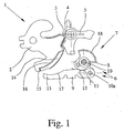
- Fig. 1 shows a motor vehicle lock 1 with a latch 2 and a lock latch 2 in a main catch 3 and a pre-latch 4 holding pawl 5.
- the latch 2 is in a prelocking position, in which the latch 2 in the pre-rest 4 is held by the pawl 5.
- the main closed position the latch 2 is held by the pawl 5 in the main catch 3.
- a prelocking is not necessarily required. Instead, a defined intermediate position, from which the latch 2 is then adjustable in its main closed position is sufficient. In the presently described embodiment, however, this intermediate position corresponds to the prelocking position.
- the motor vehicle lock 1 is equipped with a closing aid 6 for adjusting the latch 2 in the Hauptsch Anlagenstellüng. In this case, both a motor and a manual operation of the closing aid can be provided.
- the closing operation of the latch 2 comprises a cycle of movement of the drive element 8, which causes the adjustment of the latch 2 in the main closing position and then the uncoupling of the auxiliary closing lever 9 of the latch 2.
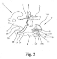
- the adjustment of the latch 2 in the main closing position in the present case also includes the adjustment of the latch 2 initially in an overstroke position (Fig. 3) with the subsequent falling back of the latch 2 in the main closed position.
- the closing process is completed only after the uncoupling of the auxiliary closing lever 9 of the latch 2.
- the closing aid 6 is designed here so that the movement cycle of the drive element 8 causes the coupling of the auxiliary closing lever 9 with the latch 2 before the adjustment of the latch 2 in the main closing position.
- the movement cycle of the drive element 8 during the closing operation preferably comprises a pivoting of the drive element 8 in both pivoting directions.
- the coupling of the auxiliary closing lever 9 with the latch 2 and the adjustment of the lock catch 2 in the main closing position with the pivoting of the drive element 8 in a pivoting direction - in Fig. 1 litisherum - connected and uncoupling with the pivoting of the drive element 8 in the opposite pivoting direction - in Fig. 1 linksherum - connected.
- the entire closing operation is preferably completely motorized. But it is also possible that the provision of the drive element 8 and thus the decoupling of the auxiliary closing lever 9 is realized by spring force in conjunction with a freewheel of the drive element 8.
- the auxiliary closing lever 9 is preferably pivotably connected to the drive element 8 in the manner of an eccentric at a location spaced from the pivot axis 10 of the drive element 8.
- the drive element 8 has a stop 11 and the auxiliary closing lever 9 has a counter-stop 12.
- the two stops 11, 12 are at the beginning of the closing operation with each other engaged and block pivoting of the auxiliary closing lever 9 relative to the drive member 8 in one direction, here in the direction of the coupled position of the auxiliary closing lever.
- the closing aid 6 is preferably designed so that the closing auxiliary lever 9 during closing by the movement cycle of the drive element 8 and with mutually engaged stop 11 and counter-stop 12 initially - without pivoting relative to the drive element 8 - comes into contact with the latch 2. This is connected to a pivoting of the drive element 8 in Fig. 1 on the right. Subsequently, the further pivoting of the drive element 8 causes pivoting of the auxiliary closing lever 9 relative to the drive element 8, the adjustment of the latch 2 in the main closed position.
- Stop 11 and counter-stop 12 are arranged so that they engage in the closing operation and after the adjustment of the latch 2 in the main closing position by the movement cycle of the drive member 8 with each other in such a way that thereby the uncoupling of the auxiliary closing lever 9 takes place from the latch 2.
- the drive element 8 - in Fig. 3 on the left - so long pivots until stop 11 and counter-stop 12 in turn come into engagement with each other.
- the further pivoting of the drive element 8 then has the blokkierenden engagement of the stops 11, 12 a common pivoting of the drive element 8 and closing auxiliary lever 9 result, until finally the starting position (Fig. 1) is reached.
- the drive element 8 and the auxiliary closing lever 9 are biased in the blocking position one another. This is preferably done by a correspondingly arranged spring.
- the bias stop 11 and counter-stop 12 are so long in blocking engagement, as long as there is no force acting against the bias. Such a force comes only to bear when the auxiliary closing lever 9 is coupled to the latch 2 or as long as the auxiliary closing lever 9 is coupled to the latch 2.
- the drive element 8, the auxiliary closing lever 9 and the latch 2 form a four-joint kinematics during the closing process. This is particularly advantageous in terms of actuation forces for adjusting the lock latch 2 in the main closed position, as can be achieved by a four-joint kinematics with little effort, a favorable gear ratio.
- the kinematics between the drive element 8 and the latch 2 is called, in which four joints are involved during the closing process. These are here the pivot axis 10 of the drive element 8, the articulation point of the auxiliary closing lever 9 on the drive element 8, the coupling of the auxiliary closing lever 9 with the latch 2 and the pivot axis of the latch 2.
- the four-joint kinematics is not mandatory, it can instead other kinematic chains be provided between the drive element 8 and the latch 2.
- a kinematics with more than four joints can be provided, which may be more favorable in terms of the transmission ratio, but requires greater design effort.
- the auxiliary closing lever 9 has a mandrel 13 and the latch 2 has a molding 14.
- the molding 14 has for this purpose a substantially radially aligned portion 15, with which the mandrel 13 of the auxiliary closing lever 9 during pivoting of the latch 2 for power transmission is engaged.
- the molding 14 has a substantially arcuate portion 16, to which the closing auxiliary lever 9 approaches during the closing operation.
- the closing auxiliary lever 9 is also equipped with a curved section 17 corresponding to the section 16 of the molding 14.
- the auxiliary closing drive 7 has here and preferably an electric motor for adjusting the drive element 8.
- an electric motor for adjusting the drive element 8.
- a pneumatic drive or the like may be provided for the drive-technical coupling, preferably with the motor, the drive element 8 preferably has a section 18 designed as a toothed rim.
- the auxiliary closing drive 7 may also have a Bowden cable, so that the drive element 8 is pivoted as described above by operating the Bowden cable.
- the pivoting of the drive element 8 can be realized in that the Bowden cable is directly coupled to the drive element 8 itself, or that the Bowden cable indirectly, for example via a transmission, is coupled to the drive element 8.
- the Bowden cable itself is operated by a motor drive, or manually.
Landscapes
- Lock And Its Accessories (AREA)
- Vehicle Body Suspensions (AREA)
Claims (13)
- Serrure pour véhicule automobile comprenant un pêne de serrure (2), avec un cliquet d'arrêt (5) retenant le pêne de serrure (2) dans un dispositif de verrouillage principal (3) et un dispositif de pré-verrouillage éventuellement présent (4), et comprenant un auxiliaire de fermeture (6), l'auxiliaire de fermeture (6) présentant un entraînement (7) - entraînement d'auxiliaire de fermeture - avec un élément d'entraînement pivotant (8) et un levier d'auxiliaire de fermeture (9) articulé de manière pivotante à l'élément d'entraînement (8), le pêne de serrure (2) pouvant être déplacé au moyen de l'entraînement d'auxiliaire de fermeture (7) par le biais de l'élément d'entraînement (8) et par le biais du levier d'auxiliaire de fermeture (9) dans une position de fermeture principale - opération de fermeture - et pour cela, le levier d'auxiliaire de fermeture (9) pouvant être accouplé au pêne de serrure (2) et l'opération de fermeture comprenant un cycle de mouvement de l'élément d'entraînement (8),
caractérisée en ce que
l'élément d'entraînement (8) peut être amené en prise avec le levier d'auxiliaire de fermeture (9) de telle sorte que le cycle de mouvement de l'élément d'entraînement (8) provoque, après le déplacement du pêne de serrure (2) dans la position de fermeture principale, le désaccouplement du levier d'auxiliaire de fermeture (9) du pêne de serrure (2). - Serrure pour véhicule automobile selon la revendication 1, caractérisée en ce que lors de l'opération de fermeture, le cycle de mouvement de l'élément d'entraînement (8) pour le déplacement du pêne de serrure (2) dans la position de fermeture principale provoque d'abord l'accouplement du levier d'auxiliaire de fermeture (9) avec le pêne de serrure (2).
- Serrure pour véhicule automobile selon la revendication 2, caractérisée en ce que lors de l'opération de fermeture, le cycle de mouvement de l'élément d'entraînement (8) comprend un pivotement de l'élément d'entraînement (8) dans les deux sens de pivotement, en ce que l'accouplement du levier d'auxiliaire de fermeture (9) avec le pêne de serrure (2) et le déplacement du pêne de serrure (2) dans la position de fermeture principale sont associés au pivotement de l'élément d'entraînement (8) dans un sens de pivotement et en ce que le désaccouplement est associé au pivotement de l'élément d'entraînement (8) dans l'autre sens de pivotement.
- Serrure pour véhicule automobile selon l'une quelconque des revendications 1 à 3, caractérisée en ce que le levier d'auxiliaire de fermeture (9) est articulé de manière pivotante à un endroit de l'élément d'entraînement (8) espacé de l'axe de pivotement (10) de l'élément d'entraînement (8).
- Serrure pour véhicule automobile selon l'une quelconque des revendications 1 à 4, caractérisée en ce que l'élément d'entraînement (8) présente une butée (11) et le levier d'auxiliaire de fermeture (9) présente une contre-butée (12) et en ce que par un pivotement du levier d'auxiliaire de fermeture (9) par rapport à l'élément d'entraînement (8), la butée (11) et la contre-butée (12) peuvent être amenées en prise l'une avec l'autre et de ce fait un pivotement supplémentaire est bloqué.
- Serrure pour véhicule automobile selon la revendication 5, caractérisée en ce que la butée (11) et la contre-butée (12) sont en prise l'une avec l'autre par blocage au début de l'opération de fermeture.
- Serrure pour véhicule automobile selon la revendication 6, caractérisée en ce que lors de l'opération de fermeture, le levier d'auxiliaire de fermeture (9), par le cycle de mouvement de l'élément d'entraînement (8) et lorsque la butée (11) et la contre-butée (12) sont en prise l'une avec l'autre, vient d'abord en appui - sans pivotement du levier d'auxiliaire de fermeture (9) par rapport à l'élément d'entraînement (8) - avec le pêne de serrure (2) puis - par pivotement du levier d'auxiliaire de fermeture (9) par rapport à l'élément d'entraînement (8) - provoque le déplacement du pêne de serrure (2).
- Serrure pour véhicule automobile selon la revendication 5 et éventuellement selon la revendication 6 ou 7, caractérisée en ce que lors de l'opération de fermeture et après le déplacement du pêne de serrure (2) dans la position de fermeture principale par le cycle de déplacement de l'élément d'entraînement (8), la butée (11) et la contre-butée (12) viennent en prise l'une avec l'autre par blocage et de ce fait le désaccouplement du levier d'auxiliaire de fermeture (9) du pêne de serrure (2) a lieu.
- Serrure pour véhicule automobile selon la revendication 5 et éventuellement selon l'une quelconque des revendications 6 à 8, caractérisée en ce que l'élément d'entraînement (8) et le levier d'auxiliaire de fermeture (9) sont précontraints dans la position de blocage mutuel.
- Serrure pour véhicule automobile selon la revendication 4 et éventuellement selon l'une quelconque des revendications 5 à 9, caractérisée en ce que l'élément d'entraînement (8), le levier d'auxiliaire de fermeture (9) et le pêne de serrure (2) forment une cinématique à quadrilatère articulé lors de l'opération de fermeture, et en ce que l'accouplement entre le levier d'auxiliaire de fermeture (9) et le pêne de serrure (2) forme lors de l'opération de fermeture une articulation de la cinématique à quadrilatère articulé.
- Serrure pour véhicule automobile selon l'une quelconque des revendications 1 à 10, caractérisée en ce que le levier d'auxiliaire de fermeture (9) présente un mandrin (13), en ce que le pêne de serrure (2) présente une formation (14) et en ce que le mandrin (13), lors de l'opération de fermeture, pour l'accouplement du levier d'auxiliaire de fermeture (9) au pêne de serrure (2) vient en prise avec la formation (14), de préférence en ce que la formation (14) présente une portion (15) orientée substantiellement radialement et/ou en ce que la formation (14) présente une portion (16) substantiellement en forme d'arc, de laquelle se rapproche le levier d'auxiliaire de fermeture (9) lors de l'opération de fermeture.
- Serrure pour véhicule automobile selon l'une quelconque des revendications 1 à 11, caractérisée en ce que l'entraînement d'auxiliaire de fermeture (7) est réalisé sous forme d'entraînement à moteur et présente de préférence un moteur électrique pour le déplacement de l'élément d'entraînement (8), de préférence en ce que l'élément d'entraînement (8) pour l'accouplement technique d'entraînement présente de préférence avec le moteur une portion (18) réalisée sous forme de couronne dentée.
- Serrure pour véhicule automobile selon l'une quelconque des revendications 1 à 12, caractérisée en ce que l'entraînement d'auxiliaire de fermeture (7) présente un câble Bowden de sorte que l'élément d'entraînement (8) puisse être pivoté par actionnement manuel ou par moteur du câble Bowden.
Applications Claiming Priority (1)
| Application Number | Priority Date | Filing Date | Title |
|---|---|---|---|
| DE200410034510 DE102004034510A1 (de) | 2004-07-15 | 2004-07-15 | Kraftfahrzeugschloß |
Publications (2)
| Publication Number | Publication Date |
|---|---|
| EP1617021A1 EP1617021A1 (fr) | 2006-01-18 |
| EP1617021B1 true EP1617021B1 (fr) | 2007-08-01 |
Family
ID=35335767
Family Applications (1)
| Application Number | Title | Priority Date | Filing Date |
|---|---|---|---|
| EP20050011821 Active EP1617021B1 (fr) | 2004-07-15 | 2005-06-01 | Serrure pour véhicule automobile |
Country Status (4)
| Country | Link |
|---|---|
| US (1) | US7261336B2 (fr) |
| EP (1) | EP1617021B1 (fr) |
| AT (1) | ATE368786T1 (fr) |
| DE (2) | DE102004034510A1 (fr) |
Cited By (2)
| Publication number | Priority date | Publication date | Assignee | Title |
|---|---|---|---|---|
| EP2803795A2 (fr) | 2013-05-17 | 2014-11-19 | Brose Schliesssysteme GmbH & Co. KG | Serrure de véhicule automobile |
| DE202014103819U1 (de) | 2014-08-18 | 2015-11-19 | BROSE SCHLIEßSYSTEME GMBH & CO. KG | Kraftfahrzeugschloss |
Families Citing this family (15)
| Publication number | Priority date | Publication date | Assignee | Title |
|---|---|---|---|---|
| DE202006018617U1 (de) * | 2006-12-08 | 2008-04-17 | Zumtobel Lighting Gmbh | Transparente Lichtbeeinflussungsplatte sowie Leuchte mit einer solchen |
| JP5423207B2 (ja) * | 2009-07-24 | 2014-02-19 | アイシン精機株式会社 | 車両用開閉体制御装置 |
| US8528950B2 (en) | 2010-02-01 | 2013-09-10 | Strattec Security Corporation | Latch mechanism and latching method |
| DE102011012650A1 (de) | 2011-02-28 | 2012-08-30 | BROSE SCHLIEßSYSTEME GMBH & CO. KG | Schloss für ein Kraftfahrzeug |
| US8684094B2 (en) | 2011-11-14 | 2014-04-01 | Halliburton Energy Services, Inc. | Preventing flow of undesired fluid through a variable flow resistance system in a well |
| DE102012017677A1 (de) * | 2012-09-07 | 2014-03-13 | Kiekert Aktiengesellschaft | Kraftfahrzeugtürschloss |
| DE102014016787A1 (de) | 2014-11-14 | 2016-05-19 | BROSE SCHLIEßSYSTEME GMBH & CO. KG | Kraftfahrzeugschloss |
| DE102016218299A1 (de) * | 2015-09-29 | 2017-03-30 | Magna Closures S.P.A. | Ein-Motor-Verriegelungsanordnung mit Kraft-Anzug und Kraft-Entriegelung mit einer weichen Öffnungsfunktion |
| DE102017209376A1 (de) * | 2016-06-07 | 2017-12-07 | Magna Closures Inc. | Fahrzeugverschluss-Verriegelungsanordnung mit Doppelklinken-Verriegelungsmechanismus |
| US10871011B2 (en) | 2018-06-08 | 2020-12-22 | Brose Schliesssysteme Gmbh & Co. Kg | Method for operating a motor vehicle lock |
| US11359418B2 (en) | 2018-07-19 | 2022-06-14 | Brose Schliesssysteme Gmbh & Co. Kg | Motor vehicle lock |
| US11619078B2 (en) | 2018-07-19 | 2023-04-04 | Brose Schliesssysteme Gmbh & Co. Kommanditgesellschaft | Motor vehicle lock |
| US10914098B2 (en) * | 2019-05-30 | 2021-02-09 | Digilock Asia Ltd. | Enclosure latch system |
| CN110259292A (zh) * | 2019-07-24 | 2019-09-20 | 杭州锐一汽配有限公司 | 汽车滑门锁用自吸驱动机构 |
| DE102020215931A1 (de) * | 2020-12-15 | 2022-06-15 | Witte Automotive Gmbh | Schließvorrichtung |
Family Cites Families (14)
| Publication number | Priority date | Publication date | Assignee | Title |
|---|---|---|---|---|
| DE3414475C1 (de) * | 1984-04-17 | 1985-12-19 | Kiekert GmbH & Co KG, 5628 Heiligenhaus | Kraftfahrzeugtürverschluß |
| JP2557005B2 (ja) * | 1991-10-15 | 1996-11-27 | 三井金属鉱業株式会社 | 車両トランク扉等のアクテイブロック装置 |
| DE4311785C2 (de) | 1993-04-09 | 1995-03-09 | Kiekert Gmbh Co Kg | Kraftfahrzeugtürverschluß, der eine Schließ- und Öffnungshilfe mit motorischem Antrieb aufweist |
| JP2855557B2 (ja) * | 1993-07-30 | 1999-02-10 | 株式会社大井製作所 | 自動車用ドアロック装置 |
| JP3216981B2 (ja) * | 1996-01-18 | 2001-10-09 | 三井金属鉱業株式会社 | 車両用スライド扉自動開閉装置 |
| FR2768764B1 (fr) * | 1997-09-19 | 1999-11-26 | Valeo Systemes De Fermetures | Serrure electrique pour portiere de vehicule |
| FR2768761B1 (fr) * | 1997-09-19 | 1999-11-26 | Valeo Systemes De Fermetures | Serrure electrique pour portiere de vehicule, comportant des moyens d'assistance a la fermeture et a l'ouverture |
| US6386599B1 (en) * | 1999-08-12 | 2002-05-14 | John Phillip Chevalier | Latch arrangement for automotive door |
| DE19828040B4 (de) * | 1998-06-24 | 2005-05-19 | Siemens Ag | Kraftunterstützte Schließeinrichtung |
| GB2339593A (en) * | 1998-07-15 | 2000-02-02 | Meritor Light Vehicle Sys Ltd | Vehicle door latch with disengageable power release |
| DE19942360C2 (de) * | 1999-09-04 | 2003-11-13 | Kiekert Ag | Kraftfahrzeugtürverschluß |
| JP4583634B2 (ja) * | 2001-02-26 | 2010-11-17 | アイシン精機株式会社 | 車両ドア開閉装置 |
| DE10133092A1 (de) | 2001-07-11 | 2003-01-30 | Huf Huelsbeck & Fuerst Gmbh | Schloß, insbesondere für Kraftfahrzeugtüren, -klappen od. dgl. |
| DE20303196U1 (de) | 2002-02-25 | 2003-07-31 | Intier Automotive Closures Inc | Fahrzeugschloß mit Schließhilfemechanismus |
-
2004
- 2004-07-15 DE DE200410034510 patent/DE102004034510A1/de not_active Withdrawn
-
2005
- 2005-06-01 DE DE200550001124 patent/DE502005001124D1/de active Active
- 2005-06-01 EP EP20050011821 patent/EP1617021B1/fr active Active
- 2005-06-01 AT AT05011821T patent/ATE368786T1/de not_active IP Right Cessation
- 2005-07-14 US US11/180,592 patent/US7261336B2/en active Active
Cited By (4)
| Publication number | Priority date | Publication date | Assignee | Title |
|---|---|---|---|---|
| EP2803795A2 (fr) | 2013-05-17 | 2014-11-19 | Brose Schliesssysteme GmbH & Co. KG | Serrure de véhicule automobile |
| DE102013008415A1 (de) | 2013-05-17 | 2014-11-20 | BROSE SCHLIEßSYSTEME GMBH & CO. KG | Kraftfahrzeugschloss |
| DE202014103819U1 (de) | 2014-08-18 | 2015-11-19 | BROSE SCHLIEßSYSTEME GMBH & CO. KG | Kraftfahrzeugschloss |
| EP2987931A1 (fr) | 2014-08-18 | 2016-02-24 | Brose Schliesssysteme GmbH & Co. KG | Serrure de véhicule automobile |
Also Published As
| Publication number | Publication date |
|---|---|
| ATE368786T1 (de) | 2007-08-15 |
| US7261336B2 (en) | 2007-08-28 |
| DE502005001124D1 (de) | 2007-09-13 |
| EP1617021A1 (fr) | 2006-01-18 |
| US20060012186A1 (en) | 2006-01-19 |
| DE102004034510A1 (de) | 2006-02-16 |
Similar Documents
| Publication | Publication Date | Title |
|---|---|---|
| EP1617021B1 (fr) | Serrure pour véhicule automobile | |
| DE10205144B4 (de) | Verriegelungsvorrichtung für ein Faltdach eines Fahrzeugs | |
| EP2859165B1 (fr) | Dispositif d'accouplement destiné à la liaison détachable d'une partie de carrosserie montée de manière à pivoter, telle que les portes d'un véhicule, le hayon ou le capot de ce dernier, à une partie structurelle d'une carrosserie du véhicule | |
| DE10242725B4 (de) | Dach eines Cabriolets mit einer Verschlußvorrichtung | |
| EP2428380B1 (fr) | Dispositif de verrouillage | |
| EP2349763B1 (fr) | Dispositif de fermeture pour la capote d'un véhicule cabriolet | |
| DE19964066B4 (de) | Verschlusseinrichtung für ein Verdeck eines Fahrzeugs | |
| EP2987931B1 (fr) | Serrure de véhicule automobile | |
| EP1655437A1 (fr) | Dispositif d'entraînement pour la manoeuvre d'un hayon de véhicule | |
| EP1149751B1 (fr) | Dispositif d' actionnement d' un adaptateur de longueur et/ou d' un dispositif de verrouillage d' un attelage automatique | |
| DE102009018188B4 (de) | Vorrichtung zum automatischen Schließen einer Fahrzeugtür | |
| EP2329976A1 (fr) | Porte coulissante pour véhicule | |
| DE112010004715T5 (de) | Fahrzeugtürverriegelung | |
| DE202020005519U1 (de) | Elektrokupplung für ein spurgebundenes Fahrzeug, automatische Kupplung mit einer derartigen Elektrokupplung | |
| EP2428381B1 (fr) | Dispositif de verrouillage | |
| EP2025853B1 (fr) | Dispositif d'entraîneur pour un dispositif d'entraînement de porte, un tel dispositif d'entraînement de porte et une porte | |
| EP3640419A1 (fr) | Serrure de véhicule automobile pour une porte de véhicule automobile | |
| DE10045026A1 (de) | Türverriegelungsvorrichtung eines Kraftfahrzeuges | |
| EP1529908A2 (fr) | Dispositif de fermeture pour capotes, hayons ou similaires d'un véhicule | |
| WO2014166854A1 (fr) | Dispositif et procédé de blocage d'un positionnement rapide d'une tige filetée | |
| WO2018050148A1 (fr) | Serrure d'ouvrant de véhicule automobile | |
| WO2017202607A1 (fr) | Ensemble de déplacement d'un panneau de fermeture pour un toit de véhicule, système pour deux toits de véhicule et procédé de fabrication d'un ensemble | |
| DE102012200640A1 (de) | Antriebsvorrichtung für eine gemeinsame Betätigung eines Zentralverschlusses und des Flügels eines Fensters oder einer Türe | |
| DE202008003372U1 (de) | Verschlussvorrichtung für ein Cabriolet-Dach | |
| EP3913181B1 (fr) | Élément de blocage de portière pourvu d'un support amovible |
Legal Events
| Date | Code | Title | Description |
|---|---|---|---|
| PUAI | Public reference made under article 153(3) epc to a published international application that has entered the european phase |
Free format text: ORIGINAL CODE: 0009012 |
|
| AK | Designated contracting states |
Kind code of ref document: A1 Designated state(s): AT BE BG CH CY CZ DE DK EE ES FI FR GB GR HU IE IS IT LI LT LU MC NL PL PT RO SE SI SK TR |
|
| AX | Request for extension of the european patent |
Extension state: AL BA HR LV MK YU |
|
| 17P | Request for examination filed |
Effective date: 20060718 |
|
| AKX | Designation fees paid |
Designated state(s): AT BE BG CH CY CZ DE DK EE ES FI FR GB GR HU IE IS IT LI LT LU MC NL PL PT RO SE SI SK TR |
|
| GRAP | Despatch of communication of intention to grant a patent |
Free format text: ORIGINAL CODE: EPIDOSNIGR1 |
|
| GRAS | Grant fee paid |
Free format text: ORIGINAL CODE: EPIDOSNIGR3 |
|
| GRAA | (expected) grant |
Free format text: ORIGINAL CODE: 0009210 |
|
| AK | Designated contracting states |
Kind code of ref document: B1 Designated state(s): AT BE BG CH CY CZ DE DK EE ES FI FR GB GR HU IE IS IT LI LT LU MC NL PL PT RO SE SI SK TR |
|
| REG | Reference to a national code |
Ref country code: GB Ref legal event code: FG4D Free format text: NOT ENGLISH |
|
| REG | Reference to a national code |
Ref country code: CH Ref legal event code: EP |
|
| REG | Reference to a national code |
Ref country code: IE Ref legal event code: FG4D Free format text: LANGUAGE OF EP DOCUMENT: GERMAN |
|
| REF | Corresponds to: |
Ref document number: 502005001124 Country of ref document: DE Date of ref document: 20070913 Kind code of ref document: P |
|
| GBT | Gb: translation of ep patent filed (gb section 77(6)(a)/1977) |
Effective date: 20070905 |
|
| ET | Fr: translation filed | ||
| PG25 | Lapsed in a contracting state [announced via postgrant information from national office to epo] |
Ref country code: LT Free format text: LAPSE BECAUSE OF FAILURE TO SUBMIT A TRANSLATION OF THE DESCRIPTION OR TO PAY THE FEE WITHIN THE PRESCRIBED TIME-LIMIT Effective date: 20070801 Ref country code: BG Free format text: LAPSE BECAUSE OF FAILURE TO SUBMIT A TRANSLATION OF THE DESCRIPTION OR TO PAY THE FEE WITHIN THE PRESCRIBED TIME-LIMIT Effective date: 20071101 Ref country code: ES Free format text: LAPSE BECAUSE OF FAILURE TO SUBMIT A TRANSLATION OF THE DESCRIPTION OR TO PAY THE FEE WITHIN THE PRESCRIBED TIME-LIMIT Effective date: 20071112 Ref country code: IS Free format text: LAPSE BECAUSE OF FAILURE TO SUBMIT A TRANSLATION OF THE DESCRIPTION OR TO PAY THE FEE WITHIN THE PRESCRIBED TIME-LIMIT Effective date: 20071201 Ref country code: NL Free format text: LAPSE BECAUSE OF FAILURE TO SUBMIT A TRANSLATION OF THE DESCRIPTION OR TO PAY THE FEE WITHIN THE PRESCRIBED TIME-LIMIT Effective date: 20070801 Ref country code: FI Free format text: LAPSE BECAUSE OF FAILURE TO SUBMIT A TRANSLATION OF THE DESCRIPTION OR TO PAY THE FEE WITHIN THE PRESCRIBED TIME-LIMIT Effective date: 20070801 |
|
| NLV1 | Nl: lapsed or annulled due to failure to fulfill the requirements of art. 29p and 29m of the patents act | ||
| PG25 | Lapsed in a contracting state [announced via postgrant information from national office to epo] |
Ref country code: PL Free format text: LAPSE BECAUSE OF FAILURE TO SUBMIT A TRANSLATION OF THE DESCRIPTION OR TO PAY THE FEE WITHIN THE PRESCRIBED TIME-LIMIT Effective date: 20070801 |
|
| REG | Reference to a national code |
Ref country code: IE Ref legal event code: FD4D |
|
| PG25 | Lapsed in a contracting state [announced via postgrant information from national office to epo] |
Ref country code: GR Free format text: LAPSE BECAUSE OF FAILURE TO SUBMIT A TRANSLATION OF THE DESCRIPTION OR TO PAY THE FEE WITHIN THE PRESCRIBED TIME-LIMIT Effective date: 20071102 Ref country code: DK Free format text: LAPSE BECAUSE OF FAILURE TO SUBMIT A TRANSLATION OF THE DESCRIPTION OR TO PAY THE FEE WITHIN THE PRESCRIBED TIME-LIMIT Effective date: 20070801 |
|
| PG25 | Lapsed in a contracting state [announced via postgrant information from national office to epo] |
Ref country code: SK Free format text: LAPSE BECAUSE OF FAILURE TO SUBMIT A TRANSLATION OF THE DESCRIPTION OR TO PAY THE FEE WITHIN THE PRESCRIBED TIME-LIMIT Effective date: 20070801 Ref country code: PT Free format text: LAPSE BECAUSE OF FAILURE TO SUBMIT A TRANSLATION OF THE DESCRIPTION OR TO PAY THE FEE WITHIN THE PRESCRIBED TIME-LIMIT Effective date: 20080102 Ref country code: IE Free format text: LAPSE BECAUSE OF FAILURE TO SUBMIT A TRANSLATION OF THE DESCRIPTION OR TO PAY THE FEE WITHIN THE PRESCRIBED TIME-LIMIT Effective date: 20070801 |
|
| PLBE | No opposition filed within time limit |
Free format text: ORIGINAL CODE: 0009261 |
|
| STAA | Information on the status of an ep patent application or granted ep patent |
Free format text: STATUS: NO OPPOSITION FILED WITHIN TIME LIMIT |
|
| PG25 | Lapsed in a contracting state [announced via postgrant information from national office to epo] |
Ref country code: SE Free format text: LAPSE BECAUSE OF FAILURE TO SUBMIT A TRANSLATION OF THE DESCRIPTION OR TO PAY THE FEE WITHIN THE PRESCRIBED TIME-LIMIT Effective date: 20071101 Ref country code: RO Free format text: LAPSE BECAUSE OF FAILURE TO SUBMIT A TRANSLATION OF THE DESCRIPTION OR TO PAY THE FEE WITHIN THE PRESCRIBED TIME-LIMIT Effective date: 20070801 |
|
| 26N | No opposition filed |
Effective date: 20080506 |
|
| BERE | Be: lapsed |
Owner name: BROSE SCHLIESSSYSTEME G.M.B.H. & CO. KG Effective date: 20080630 |
|
| PG25 | Lapsed in a contracting state [announced via postgrant information from national office to epo] |
Ref country code: MC Free format text: LAPSE BECAUSE OF NON-PAYMENT OF DUE FEES Effective date: 20080630 |
|
| PG25 | Lapsed in a contracting state [announced via postgrant information from national office to epo] |
Ref country code: BE Free format text: LAPSE BECAUSE OF NON-PAYMENT OF DUE FEES Effective date: 20080630 |
|
| PG25 | Lapsed in a contracting state [announced via postgrant information from national office to epo] |
Ref country code: EE Free format text: LAPSE BECAUSE OF FAILURE TO SUBMIT A TRANSLATION OF THE DESCRIPTION OR TO PAY THE FEE WITHIN THE PRESCRIBED TIME-LIMIT Effective date: 20070801 |
|
| PG25 | Lapsed in a contracting state [announced via postgrant information from national office to epo] |
Ref country code: SI Free format text: LAPSE BECAUSE OF FAILURE TO SUBMIT A TRANSLATION OF THE DESCRIPTION OR TO PAY THE FEE WITHIN THE PRESCRIBED TIME-LIMIT Effective date: 20070801 |
|
| PG25 | Lapsed in a contracting state [announced via postgrant information from national office to epo] |
Ref country code: CY Free format text: LAPSE BECAUSE OF FAILURE TO SUBMIT A TRANSLATION OF THE DESCRIPTION OR TO PAY THE FEE WITHIN THE PRESCRIBED TIME-LIMIT Effective date: 20070801 |
|
| PG25 | Lapsed in a contracting state [announced via postgrant information from national office to epo] |
Ref country code: AT Free format text: LAPSE BECAUSE OF NON-PAYMENT OF DUE FEES Effective date: 20080601 |
|
| REG | Reference to a national code |
Ref country code: CH Ref legal event code: PL |
|
| PG25 | Lapsed in a contracting state [announced via postgrant information from national office to epo] |
Ref country code: LI Free format text: LAPSE BECAUSE OF NON-PAYMENT OF DUE FEES Effective date: 20090630 Ref country code: CH Free format text: LAPSE BECAUSE OF NON-PAYMENT OF DUE FEES Effective date: 20090630 |
|
| PG25 | Lapsed in a contracting state [announced via postgrant information from national office to epo] |
Ref country code: HU Free format text: LAPSE BECAUSE OF FAILURE TO SUBMIT A TRANSLATION OF THE DESCRIPTION OR TO PAY THE FEE WITHIN THE PRESCRIBED TIME-LIMIT Effective date: 20080202 Ref country code: LU Free format text: LAPSE BECAUSE OF NON-PAYMENT OF DUE FEES Effective date: 20080601 |
|
| PG25 | Lapsed in a contracting state [announced via postgrant information from national office to epo] |
Ref country code: TR Free format text: LAPSE BECAUSE OF FAILURE TO SUBMIT A TRANSLATION OF THE DESCRIPTION OR TO PAY THE FEE WITHIN THE PRESCRIBED TIME-LIMIT Effective date: 20070801 |
|
| PG25 | Lapsed in a contracting state [announced via postgrant information from national office to epo] |
Ref country code: IT Free format text: LAPSE BECAUSE OF NON-PAYMENT OF DUE FEES Effective date: 20080630 |
|
| REG | Reference to a national code |
Ref country code: DE Ref legal event code: R082 Ref document number: 502005001124 Country of ref document: DE Representative=s name: GOTTSCHALD PATENTANWALTSKANZLEI, DE Ref country code: DE Ref legal event code: R082 Ref document number: 502005001124 Country of ref document: DE Representative=s name: GOTTSCHALD PATENTANWAELTE PARTNERSCHAFT MBB, DE |
|
| REG | Reference to a national code |
Ref country code: FR Ref legal event code: PLFP Year of fee payment: 12 |
|
| REG | Reference to a national code |
Ref country code: FR Ref legal event code: PLFP Year of fee payment: 13 |
|
| REG | Reference to a national code |
Ref country code: FR Ref legal event code: PLFP Year of fee payment: 14 |
|
| PGFP | Annual fee paid to national office [announced via postgrant information from national office to epo] |
Ref country code: FR Payment date: 20230510 Year of fee payment: 19 Ref country code: DE Payment date: 20230630 Year of fee payment: 19 Ref country code: CZ Payment date: 20230517 Year of fee payment: 19 |
|
| P01 | Opt-out of the competence of the unified patent court (upc) registered |
Effective date: 20230803 |
|
| PGFP | Annual fee paid to national office [announced via postgrant information from national office to epo] |
Ref country code: GB Payment date: 20230504 Year of fee payment: 19 |