EP1617021B1 - Motor vehicle lock - Google Patents
Motor vehicle lock Download PDFInfo
- Publication number
- EP1617021B1 EP1617021B1 EP20050011821 EP05011821A EP1617021B1 EP 1617021 B1 EP1617021 B1 EP 1617021B1 EP 20050011821 EP20050011821 EP 20050011821 EP 05011821 A EP05011821 A EP 05011821A EP 1617021 B1 EP1617021 B1 EP 1617021B1
- Authority
- EP
- European Patent Office
- Prior art keywords
- locking
- drive element
- latch
- lever
- aid
- Prior art date
- Legal status (The legal status is an assumption and is not a legal conclusion. Google has not performed a legal analysis and makes no representation as to the accuracy of the status listed.)
- Active
Links
- 230000033001 locomotion Effects 0.000 claims abstract description 23
- 230000008878 coupling Effects 0.000 claims abstract description 16
- 238000010168 coupling process Methods 0.000 claims abstract description 16
- 238000005859 coupling reaction Methods 0.000 claims abstract description 16
- 230000015572 biosynthetic process Effects 0.000 claims description 5
- 230000000903 blocking effect Effects 0.000 claims description 5
- 238000013459 approach Methods 0.000 claims description 2
- 238000006073 displacement reaction Methods 0.000 claims 4
- 238000000034 method Methods 0.000 abstract description 5
- 238000000465 moulding Methods 0.000 description 5
- 230000005540 biological transmission Effects 0.000 description 3
- 238000010276 construction Methods 0.000 description 2
- 230000002349 favourable effect Effects 0.000 description 2
- 230000001419 dependent effect Effects 0.000 description 1
- 238000011161 development Methods 0.000 description 1
- 230000018109 developmental process Effects 0.000 description 1
- 230000000694 effects Effects 0.000 description 1
- 238000004519 manufacturing process Methods 0.000 description 1
Images

Classifications
-
- E—FIXED CONSTRUCTIONS
- E05—LOCKS; KEYS; WINDOW OR DOOR FITTINGS; SAFES
- E05B—LOCKS; ACCESSORIES THEREFOR; HANDCUFFS
- E05B81/00—Power-actuated vehicle locks
- E05B81/12—Power-actuated vehicle locks characterised by the function or purpose of the powered actuators
- E05B81/20—Power-actuated vehicle locks characterised by the function or purpose of the powered actuators for assisting final closing or for initiating opening
-
- Y—GENERAL TAGGING OF NEW TECHNOLOGICAL DEVELOPMENTS; GENERAL TAGGING OF CROSS-SECTIONAL TECHNOLOGIES SPANNING OVER SEVERAL SECTIONS OF THE IPC; TECHNICAL SUBJECTS COVERED BY FORMER USPC CROSS-REFERENCE ART COLLECTIONS [XRACs] AND DIGESTS
- Y10—TECHNICAL SUBJECTS COVERED BY FORMER USPC
- Y10T—TECHNICAL SUBJECTS COVERED BY FORMER US CLASSIFICATION
- Y10T292/00—Closure fasteners
- Y10T292/08—Bolts
- Y10T292/1043—Swinging
- Y10T292/1044—Multiple head
- Y10T292/1045—Operating means
- Y10T292/1047—Closure
-
- Y—GENERAL TAGGING OF NEW TECHNOLOGICAL DEVELOPMENTS; GENERAL TAGGING OF CROSS-SECTIONAL TECHNOLOGIES SPANNING OVER SEVERAL SECTIONS OF THE IPC; TECHNICAL SUBJECTS COVERED BY FORMER USPC CROSS-REFERENCE ART COLLECTIONS [XRACs] AND DIGESTS
- Y10—TECHNICAL SUBJECTS COVERED BY FORMER USPC
- Y10T—TECHNICAL SUBJECTS COVERED BY FORMER US CLASSIFICATION
- Y10T292/00—Closure fasteners
- Y10T292/08—Bolts
- Y10T292/1043—Swinging
- Y10T292/1075—Operating means
- Y10T292/1082—Motor
Definitions
- the present invention relates to a motor vehicle lock having the features of the preamble of claim 1.
- the motor vehicle lock is particularly suitable as a side door lock, but can be used as a sliding door lock, rear door lock, tailgate lock or hood lock use.
- motor vehicle locks are increasingly equipped with a closing auxiliary function.
- the auxiliary closing function ensures that the motor vehicle lock is transferred from an intermediate position out motor to the fully closed position.
- the intermediate position corresponds in a motor vehicle lock with latch and pawl usually the prelocking the latch.
- a closing auxiliary drive and a closing auxiliary lever to adjust the latch of the motor vehicle lock from a prelocking in a main closed position.
- this closing operation of the closing auxiliary lever comes into engagement with a arranged on the lock latch molding, pushes the latch in the main closed position and finally remains in a position in which the auxiliary closing lever blocks the return of the latch. Only when lifting the pawl, so when the vehicle door is to be opened, and the closing auxiliary lever is disengaged from the latch.
- the lifting of the auxiliary closing lever ie the decoupling of the auxiliary closing lever of the latch, is here directly connected to the lifting of the pawl. This is realized by an additional lever mechanism, which requires a high design effort.
- a motor vehicle lock is known ( DE 43 11 785 A1 ), in which the pawl itself is used as a closing auxiliary lever.
- a lever mechanism is provided, on the one hand allows the adjustment of the latch in the main closing position by means of the pawl and on the other hand, the lifting of the pawl itself.
- Such a construction is expensive and has disadvantages with respect to a flexible arrangement of the various components in the motor vehicle lock.
- the known motor vehicle lock ( DE 203 03 196 U1 ), from which the present invention proceeds, is also equipped with a motorized closing aid.
- the closing aid shows a closing auxiliary drive with a pivotable drive element and a pivotally hinged to the drive element closing auxiliary lever.
- the closing auxiliary lever has a slotted guide, which can be brought into engagement with an intermediate element. The slide guide thus causes a motion guide of the auxiliary closing lever such that the auxiliary closing lever is coupled at the beginning of the closing operation with the latch and is decoupled from the latch at the end of the closing process.
- a disadvantage of the motor vehicle lock forming the starting point is the fundamental susceptibility to failure of the slide guide described. This can lead to frictional losses or jamming. Furthermore, it is disadvantageous that the components required here, in particular the slotted guide itself, are expensive to manufacture. Finally, it should be noted that in principle the necessary coupling between the auxiliary closing lever and the intermediate element is to be considered in the construction, which leads to undesirable structural limitations.
- the present invention is based on the problem to design the known motor vehicle lock such and further, that a high reliability with high design flexibility and is guaranteed with little effort.
- the auxiliary closing drive forms with the auxiliary closing lever to some extent a closed system, which can fulfill its function - apart from the coupling with the latch - largely independent of other components of the motor vehicle lock. This leads to a constructive decoupling and as a result to particularly simple structural solutions.
- the stop and the counter stop are engaged with each other and block the pivoting of the auxiliary closing lever relative to the drive element in one direction. This initially ensures that the auxiliary closing lever can not interfere with the movement of the latch, as long as this is not desirable.
- the closing aid is now preferably carried out so that the closing auxiliary lever during closing by the movement cycle of the drive element and engaged with each stop and counter-stop initially without pivoting relative to the drive element comes into contact with the latch and then with a pivoting relative to the drive element, the corresponding adjustment the latch causes.
- stop and counter-stop are designed so that they come so close to each other during the closing operation and after the adjustment of the latch by the movement cycle of the drive element, that the uncoupling of the auxiliary closing lever takes place.
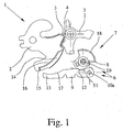
- Fig. 1 shows a motor vehicle lock 1 with a latch 2 and a lock latch 2 in a main catch 3 and a pre-latch 4 holding pawl 5.
- the latch 2 is in a prelocking position, in which the latch 2 in the pre-rest 4 is held by the pawl 5.
- the main closed position the latch 2 is held by the pawl 5 in the main catch 3.
- a prelocking is not necessarily required. Instead, a defined intermediate position, from which the latch 2 is then adjustable in its main closed position is sufficient. In the presently described embodiment, however, this intermediate position corresponds to the prelocking position.
- the motor vehicle lock 1 is equipped with a closing aid 6 for adjusting the latch 2 in the Hauptsch Anlagenstellüng. In this case, both a motor and a manual operation of the closing aid can be provided.
- the closing operation of the latch 2 comprises a cycle of movement of the drive element 8, which causes the adjustment of the latch 2 in the main closing position and then the uncoupling of the auxiliary closing lever 9 of the latch 2.
- the adjustment of the latch 2 in the main closing position in the present case also includes the adjustment of the latch 2 initially in an overstroke position (Fig. 3) with the subsequent falling back of the latch 2 in the main closed position.
- the closing process is completed only after the uncoupling of the auxiliary closing lever 9 of the latch 2.
- the closing aid 6 is designed here so that the movement cycle of the drive element 8 causes the coupling of the auxiliary closing lever 9 with the latch 2 before the adjustment of the latch 2 in the main closing position.
- the movement cycle of the drive element 8 during the closing operation preferably comprises a pivoting of the drive element 8 in both pivoting directions.
- the coupling of the auxiliary closing lever 9 with the latch 2 and the adjustment of the lock catch 2 in the main closing position with the pivoting of the drive element 8 in a pivoting direction - in Fig. 1 litisherum - connected and uncoupling with the pivoting of the drive element 8 in the opposite pivoting direction - in Fig. 1 linksherum - connected.
- the entire closing operation is preferably completely motorized. But it is also possible that the provision of the drive element 8 and thus the decoupling of the auxiliary closing lever 9 is realized by spring force in conjunction with a freewheel of the drive element 8.
- the auxiliary closing lever 9 is preferably pivotably connected to the drive element 8 in the manner of an eccentric at a location spaced from the pivot axis 10 of the drive element 8.
- the drive element 8 has a stop 11 and the auxiliary closing lever 9 has a counter-stop 12.
- the two stops 11, 12 are at the beginning of the closing operation with each other engaged and block pivoting of the auxiliary closing lever 9 relative to the drive member 8 in one direction, here in the direction of the coupled position of the auxiliary closing lever.
- the closing aid 6 is preferably designed so that the closing auxiliary lever 9 during closing by the movement cycle of the drive element 8 and with mutually engaged stop 11 and counter-stop 12 initially - without pivoting relative to the drive element 8 - comes into contact with the latch 2. This is connected to a pivoting of the drive element 8 in Fig. 1 on the right. Subsequently, the further pivoting of the drive element 8 causes pivoting of the auxiliary closing lever 9 relative to the drive element 8, the adjustment of the latch 2 in the main closed position.
- Stop 11 and counter-stop 12 are arranged so that they engage in the closing operation and after the adjustment of the latch 2 in the main closing position by the movement cycle of the drive member 8 with each other in such a way that thereby the uncoupling of the auxiliary closing lever 9 takes place from the latch 2.
- the drive element 8 - in Fig. 3 on the left - so long pivots until stop 11 and counter-stop 12 in turn come into engagement with each other.
- the further pivoting of the drive element 8 then has the blokkierenden engagement of the stops 11, 12 a common pivoting of the drive element 8 and closing auxiliary lever 9 result, until finally the starting position (Fig. 1) is reached.
- the drive element 8 and the auxiliary closing lever 9 are biased in the blocking position one another. This is preferably done by a correspondingly arranged spring.
- the bias stop 11 and counter-stop 12 are so long in blocking engagement, as long as there is no force acting against the bias. Such a force comes only to bear when the auxiliary closing lever 9 is coupled to the latch 2 or as long as the auxiliary closing lever 9 is coupled to the latch 2.
- the drive element 8, the auxiliary closing lever 9 and the latch 2 form a four-joint kinematics during the closing process. This is particularly advantageous in terms of actuation forces for adjusting the lock latch 2 in the main closed position, as can be achieved by a four-joint kinematics with little effort, a favorable gear ratio.
- the kinematics between the drive element 8 and the latch 2 is called, in which four joints are involved during the closing process. These are here the pivot axis 10 of the drive element 8, the articulation point of the auxiliary closing lever 9 on the drive element 8, the coupling of the auxiliary closing lever 9 with the latch 2 and the pivot axis of the latch 2.
- the four-joint kinematics is not mandatory, it can instead other kinematic chains be provided between the drive element 8 and the latch 2.
- a kinematics with more than four joints can be provided, which may be more favorable in terms of the transmission ratio, but requires greater design effort.
- the auxiliary closing lever 9 has a mandrel 13 and the latch 2 has a molding 14.
- the molding 14 has for this purpose a substantially radially aligned portion 15, with which the mandrel 13 of the auxiliary closing lever 9 during pivoting of the latch 2 for power transmission is engaged.
- the molding 14 has a substantially arcuate portion 16, to which the closing auxiliary lever 9 approaches during the closing operation.
- the closing auxiliary lever 9 is also equipped with a curved section 17 corresponding to the section 16 of the molding 14.
- the auxiliary closing drive 7 has here and preferably an electric motor for adjusting the drive element 8.
- an electric motor for adjusting the drive element 8.
- a pneumatic drive or the like may be provided for the drive-technical coupling, preferably with the motor, the drive element 8 preferably has a section 18 designed as a toothed rim.
- the auxiliary closing drive 7 may also have a Bowden cable, so that the drive element 8 is pivoted as described above by operating the Bowden cable.
- the pivoting of the drive element 8 can be realized in that the Bowden cable is directly coupled to the drive element 8 itself, or that the Bowden cable indirectly, for example via a transmission, is coupled to the drive element 8.
- the Bowden cable itself is operated by a motor drive, or manually.
Landscapes
- Lock And Its Accessories (AREA)
- Vehicle Body Suspensions (AREA)
Abstract
Description
Die vorliegende Erfindung betrifft ein Kraftfahrzeugschloß mit den Merkmalen des Oberbegriffs von Anspruch 1. Das Kraftfahrzeugschloß ist in besonderem Maße als Seitentürschloß geeignet, kann aber als Schiebetürschloß, Hecktürschloß, Heckklappenschloß oder Haubenschloß Verwendung finden.The present invention relates to a motor vehicle lock having the features of the preamble of
Zur Komforterhöhung und um reproduzierbar einen optimalen Schließvorgang gewährleisten zu können, werden Kraftfahrzeugschlösser zunehmend mit einer Schließhilfsfunktion ausgestattet. Die Schließhilfsfunktion sorgt dafür, daß das Kraftfahrzeugschloß aus einer Zwischenstellung heraus motorisch in die vollständig geschlossene Stellung überführt wird. Die Zwischenstellung entspricht bei einem Kraftfahrzeugschloß mit Schloßfalle und Sperrklinke in der Regel der Vorschließstellung der Schloßfalle.For comfort increase and to ensure reproducible optimal closing operation, motor vehicle locks are increasingly equipped with a closing auxiliary function. The auxiliary closing function ensures that the motor vehicle lock is transferred from an intermediate position out motor to the fully closed position. The intermediate position corresponds in a motor vehicle lock with latch and pawl usually the prelocking the latch.
Bei einem bekannten Kraftfahrzeugschloß (
Ferner ist ein Kraftfahrzeugschloß bekannt (
Das bekannte Kraftfahrzeugschloß (
Nachteilig bei dem den Ausgangspunkt bildenden Kraftfahrzeugschloß ist die grundsätzliche Fehleranfälligkeit der beschriebenen Kulissenführung. Hier kann es zu Reibverlusten oder Verklemmungen kommen. Ferner ist nachteilig, daß die hier benötigten Komponenten, insbesondere die Kulissenführung selbst, aufwendig zu fertigen sind. Schließlich darf darauf hingewiesen werden, daß bei der Konstruktion grundsätzlich die notwendige Kopplung zwischen dem Schließhilfshebel und dem Zwischenelement zu berücksichtigen ist, was zu ungewünschten konstruktiven Beschränkungen führt.A disadvantage of the motor vehicle lock forming the starting point is the fundamental susceptibility to failure of the slide guide described. This can lead to frictional losses or jamming. Furthermore, it is disadvantageous that the components required here, in particular the slotted guide itself, are expensive to manufacture. Finally, it should be noted that in principle the necessary coupling between the auxiliary closing lever and the intermediate element is to be considered in the construction, which leads to undesirable structural limitations.
Der vorliegenden Erfindung liegt das Problem zugrunde, das bekannte Kraftfahrzeugschloß derart auszugestalten und weiterzubilden, daß eine hohe Funktionssicherheit bei hoher konstruktiver Flexibilität und mit geringem Aufwand gewährleistet ist.The present invention is based on the problem to design the known motor vehicle lock such and further, that a high reliability with high design flexibility and is guaranteed with little effort.
Das obige Problem wird bei einem Kraftfahrzeugschloß mit den Merkmalen des Oberbegriffs von Anspruch 1 durch die Merkmale des kennzeichnenden Teils von Anspruch 1 gelöst. Vorteilhafte Weiterbildungen sind Gegenstand der Unteransprüche.The above problem is solved in a motor vehicle lock with the features of the preamble of
Wesentlich ist die Erkenntnis, daß eine geeignete Kopplung zwischen Antriebselement und Schließhilfshebel ursächlich dafür sein kann, daß der Bewegungszyklus des Antriebselements nach der Verstellung der Schloßfalle in die Hauptschließstellung das Entkuppeln des Schließhilfshebels von der Schloßfalle bewirkt.It is essential to realize that a suitable coupling between the drive element and closing auxiliary lever can be the cause of the fact that the movement cycle of the drive element after the adjustment of the latch in the main closing position causes the uncoupling of the closing auxiliary lever of the lock latch.
Der Schließhilfsantrieb bildet mit dem Schließhilfshebel gewissermaßen ein abgeschlossenes System, das seine Funktion - abgesehen von der Kupplung mit der Schloßfalle - weitgehend unabhängig von weiteren Komponenten des Kraftfahrzeugschlosses erfüllen kann. Dies führt zu einer konstruktiven Entkopplung und im Ergebnis zu besonders einfachen konstruktiven Lösungen.The auxiliary closing drive forms with the auxiliary closing lever to some extent a closed system, which can fulfill its function - apart from the coupling with the latch - largely independent of other components of the motor vehicle lock. This leads to a constructive decoupling and as a result to particularly simple structural solutions.
Eine besonders einfache und damit robuste konstruktive Ausgestaltung zeigt sich dann, wenn der Schließhilfshebel an einer von der Schwenkachse des Antriebselements beabstandeten Stelle nach Art eines Exzenters an dem Antriebselements angelenkt ist. Dann ist nämlich lediglich ein Anschlag am Antriebselement und ein korrespondierender Gegenanschlag am Schließhilfshebel notwendig, um das Entkuppeln des Schließhilfshebels von der Schloßfalle durch den Bewegungszyklus des Antriebselements bewirken zu können.A particularly simple and thus robust structural design is shown when the closing auxiliary lever is articulated to the drive element at a location spaced from the pivot axis of the drive element in the manner of an eccentric. Then only a stop on the drive element and a corresponding counter-stop on the auxiliary closing lever is necessary in order to be able to effect the uncoupling of the auxiliary closing lever from the latch by the movement cycle of the drive element.
Zu Beginn des Schließvorgangs stehen der Anschlag und der Gegenanschlag miteinander in Eingriff und blockieren das Verschwenken des Schließhilfshebels gegenüber dem Antriebselement in einer Richtung. Dadurch wird zunächst sichergestellt, daß der Schließhilfshebel nicht in die Bewegung der Schloßfalle eingreifen kann, so lange dies nicht erwünscht ist.At the beginning of the closing operation, the stop and the counter stop are engaged with each other and block the pivoting of the auxiliary closing lever relative to the drive element in one direction. This initially ensures that the auxiliary closing lever can not interfere with the movement of the latch, as long as this is not desirable.
Die Schließhilfe ist nun vorzugsweise so ausgeführt, daß der Schließhilfshebel beim Schließvorgang durch den Bewegungszyklus des Antriebselements und bei miteinander in Eingriff befindlichen Anschlag und Gegenanschlag zunächst ohne Verschwenken gegenüber dem Antriebselement in Anlage mit der Schloßfalle kommt und dann unter einem Verschwenken gegenüber dem Antriebselement die entsprechende Verstellung der Schloßfalle bewirkt.The closing aid is now preferably carried out so that the closing auxiliary lever during closing by the movement cycle of the drive element and engaged with each stop and counter-stop initially without pivoting relative to the drive element comes into contact with the latch and then with a pivoting relative to the drive element, the corresponding adjustment the latch causes.
Ganz bevorzugt ist es weiter, daß Anschlag und Gegenanschlag so ausgeführt sind, daß sie beim Schließvorgang und nach der Verstellung der Schloßfalle durch den Bewegungszyklus des Antriebselements derart miteinander in Eingriff kommen, daß das Entkuppeln des Schließhilfshebels erfolgt. Damit ist gemeint, daß die Bewegung des Antriebselements über die Anschläge so auf den Schließhilfshebel übertragen wird, daß dieser aus der mit der Schloßfalle kuppelnden Stellung gelöst wird. Mit einfachsten konstruktiven Mitteln wird so der volle Funktionsumfang einer Schließhilfe inklusive des Kuppelns des Schließhilfshebels mit der Schloßfalle sowie des Entkuppelns des Schließhilfshebels von der Schloßfalle gewährleistet.Quite preferably, it is further that stop and counter-stop are designed so that they come so close to each other during the closing operation and after the adjustment of the latch by the movement cycle of the drive element, that the uncoupling of the auxiliary closing lever takes place. This means that the movement of the drive element is transmitted via the stops so on the auxiliary closing lever that this from the with the latch coupling position is solved. With the simplest design means so the full functionality of a closing aid including the coupling of the auxiliary closing lever with the latch and the decoupling of the auxiliary closing lever is ensured by the latch.
Weitere Einzelheiten, Merkmale, Ziele und Vorteile der vorliegenden Erfindung werden nachfolgend anhand der Zeichnung eines bevorzugten Ausführungsbeispiels näher erläutert. In der Zeichnung zeigt
- Fig. 1
- ein erfindungsgemäßes Kraftfahrzeugschloß mit der Schloßfalle in Vorschließstellung und entkuppeltem Schließhilfshebel,
- Fig. 2
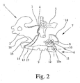
- das Kraftfahrzeugschloß aus Fig. 1 mit gekuppeltem Schließhilfshebel,
- Fig. 3
- das Kraftfahrzeugschloß aus Fig. 1 mit der Schloßfalle in Überhubstellung.
- Fig. 1
- an inventive motor vehicle lock with the latch in prelocking and uncoupled closing auxiliary lever,
- Fig. 2
- the motor vehicle lock of FIG. 1 with coupled closing auxiliary lever,
- Fig. 3
- the motor vehicle lock of Fig. 1 with the latch in overstroke position.
In den Figuren der Zeichnung werden für gleiche oder ähnliche Teile die selben Bezugszeichen verwendet. Damit soll angedeutet werden, daß entsprechende oder vergleichbare Eigenschaften und Vorteile erreicht werden, auch wenn eine wiederholte Beschreibung dieser Teile unterbleibt.In the figures of the drawing, the same reference numerals are used for the same or similar parts. This is intended to indicate that corresponding or comparable properties and advantages are achieved, even if a repeated description of these parts is omitted.
Fig. 1 zeigt ein Kraftfahrzeugschloß 1 mit einer Schloßfalle 2 und einer die Schloßfalle 2 in einer Hauptrast 3 bzw. einer Vorrast 4 haltenden Sperrklinke 5. In Fig. 1 befindet sich die Schloßfalle 2 in einer Vorschließstellung, in der die Schloßfalle 2 in der Vorrast 4 von der Sperrklinke 5 gehalten wird. In der Hauptschließstellung wird die Schloßfalle 2 von der Sperrklinke 5 in der Hauptrast 3 gehalten. Für die hier offenbarte Erfindung ist eine Vorschließstellung nicht zwangsläufig erforderlich. Statt dessen reicht eine definierte Zwischenstellung, aus der die Schloßfalle 2 dann in ihre Hauptschließstellung verstellbar ist. Im vorliegend beschriebenen Ausführungsbeispiel entspricht diese Zwischenstellung allerdings der Vorschließstellung.
Das Kraftfahrzeugschloß 1 ist mit einer Schließhilfe 6 zur Verstellung der Schloßfalle 2 in die Hauptschließstellüng ausgestattet. Dabei kann sowohl ein motorischer als auch ein manueller Betrieb der Schließhilfe vorgesehen sein.Fig. 1 shows a
The
Die Schließhilfe 6 weist einen Antrieb 7 - Schließhilfsantrieb - mit einem Antriebselement 8 und einen Schließhilfshebel 9 auf. Das Antriebselement 8 ist um eine Schwenkachse 10 schwenkbar gelagert. Der Schließhilfshebel 9 ist an dem Antriebselement 8, um eine Schwenkachse l0a schwenkbar, angelenkt. Die Schwenkachse 10 des Antriebselements 8 und die Schwenkachse l0a des Schließhilfshebels 9 sind vorzugsweise parallel zueinander ausgerichtet:
- Die
Schloßfalle 2 ist mittels desSchließhilfsantriebs 7 über dasAntriebselement 8 und über denSchließhilfshebel 9 in die Hauptschließstellung verstellbar. Hierfür ist derSchließhilfshebel 9 mit derSchloßfalle 2 kuppelbar (Fig. 2). Die Verstellung derSchloßfalle 2 in die Hauptschließstellung wird als Schließvorgang bezeichnet.
- The
latch 2 is adjustable by means of theauxiliary closing drive 7 via thedrive element 8 and via theauxiliary closing lever 9 in the main closed position. For this purpose, the closingauxiliary lever 9 with thelatch 2 can be coupled (Fig. 2). The adjustment of thelatch 2 in the main closing position is referred to as closing.
Der Schließvorgang der Schloßfalle 2 umfaßt einen Bewegungszyklus des Antriebselements 8, der die Verstellung der Schloßfalle 2 in die Hauptschließstellung und anschließend das Entkuppeln des Schließhilfshebels 9 von der Schloßfalle 2 bewirkt. Die Verstellung der Schloßfalle 2 in die Hauptschließstellung umfaßt vorliegend auch die Verstellung der Schloßfalle 2 zunächst in eine Überhubstellung (Fig. 3) mit dem anschließenden Zurückfallen der Schloßfalle 2 in die Hauptschließstellung. Der Schließvorgang ist erst nach dem Entkuppeln des Schließhilfshebels 9 von der Schloßfalle 2 beendet.The closing operation of the
Es darf schon hier darauf hingewiesen werden, daß ursächlich für das Entkuppeln des Schließhilfshebels 9 von der Schloßfalle 2 durch den Bewegungszyklus des Antriebselements 8 die besondere Ausgestaltung der Kopplung zwischen dem Antriebselement 8 einerseits und dem Schließhilfshebel 9 andererseits ist. Dies wird im folgenden noch näher erläutert.It may already be pointed out here that the cause of the decoupling of the
Die Schließhilfe 6 ist hier so ausgeführt, daß der Bewegungszyklus des Antriebselements 8 vor der Verstellung der Schloßfalle 2 in die Hauptschließstellung zunächst das Kuppeln des Schließhilfshebels 9 mit der Schloßfalle 2 bewirkt.The
Der Bewegungszyklus des Antriebselements 8 umfaßt beim Schließvorgang vorzugsweise ein Verschwenken des Antriebselements 8 in beide Schwenkrichtungen. Dabei ist das Kuppeln des Schließhilfshebels 9 mit der Schloßfalle 2 und die Verstellung der Schloßfalle 2 in die Hauptschließstellung mit dem Verschwenken des Antriebselements 8 in eine Schwenkrichtung - in Fig. 1 rechtsherum - verbunden und das Entkuppeln mit dem Verschwenken des Antriebselements 8 in der entgegengesetzten Schwenkrichtung - in Fig. 1 linksherum - verbunden.The movement cycle of the
Der gesamte Schließvorgang erfolgt vorzugsweise vollständig motorisch. Es ist aber auch möglich, daß die Rückstellung des Antriebselements 8 und damit das Entkuppeln des Schließhilfshebels 9 durch Federkraft in Verbindung mit einem Freilauf des Antriebselements 8 realisiert wird.The entire closing operation is preferably completely motorized. But it is also possible that the provision of the
Der Schließhilfshebel 9 ist vorzugsweise nach Art eines Exzenters an einer von der Schwenkachse 10 des Antriebselements 8 beabstandeten Stelle an dem Antriebselement 8 schwenkbar angelenkt. Das Antriebselement 8 weist einen Anschlag 11 und der Schließhilfshebel 9 weist einen Gegenanschlag 12 auf. Die beiden Anschläge 11, 12 stehen zu Begin des Schließvorgangs miteinander in Eingriff und blockieren ein Verschwenken des Schließhilfshebels 9 gegenüber dem Antriebselement 8 in eine Richtung, hier in Richtung der gekuppelten Stellung des Schließhilfshebels 9.The
Die Schließhilfe 6 ist vorzugsweise so ausgeführt, daß der Schließhilfshebel 9 beim Schließvorgang durch den Bewegungszyklus des Antriebselements 8 und bei miteinander in Eingriff befindlichen Anschlag 11 und Gegenanschlag 12 zunächst - ohne ein Verschwenken gegenüber dem Antriebselement 8 - in Anlage mit der Schloßfalle 2 kommt. Dies ist mit einem Verschwenken des Antriebselements 8 in Fig. 1 rechtsherum verbunden. Anschließend bewirkt das weitere Verschwenken des Antriebselements 8 unter einem Verschwenken des Schließhilfshebels 9 gegenüber dem Antriebselement 8 die Verstellung der Schloßfalle 2 in die Hauptschließstellung.The
Anschlag 11 und Gegenanschlag 12 sind so angeordnet, daß sie beim Schließvorgang und nach der Verstellung der Schloßfalle 2 in die Hauptschließstellung durch den Bewegungszyklus des Antriebselements 8 derart miteinander in Eingriff kommen, daß dadurch das Entkuppeln des Schließhilfshebels 9 von der Schloßfalle 2 erfolgt. Dabei wird im hier gezeigten Ausführungsbeispiel das Antriebselement 8 - in Fig. 3 linksherum - so lange verschwenkt, bis Anschlag 11 und Gegenanschlag 12 wiederum miteinander in Eingriff kommen. Das weitere Verschwenken des Antriebselements 8 hat dann durch den blokkierenden Eingriff der Anschläge 11, 12 ein gemeinsames Verschwenken von Antriebselement 8 und Schließhilfshebel 9 zur Folge, bis letztendlich wieder die Ausgangsstellung (Fig. 1) erreicht ist.
Das Antriebselement 8 und der Schließhilfshebel 9 sind in die einander blokkierende Stellung vorgespannt. Dies geschieht vorzugsweise durch eine entsprechend angeordnete Feder. Durch die Vorspannung sind Anschlag 11 und Gegenanschlag 12 so lange in blockierendem Eingriff, so lange keine entgegen der Vorspannung wirkende Kraft vorliegt. Eine solche Kraft kommt erst dann zum Tragen, wenn der Schließhilfshebel 9 mit der Schloßfalle 2 gekuppelt ist bzw. solange der Schließhilfshebel 9 mit der Schloßfalle 2 gekuppelt ist.The
Das Antriebselement 8, der Schließhilfshebel 9 und die Schloßfalle 2 bilden beim Schließvorgang eine Viergelenkkinematik. Dies ist besonders hinsichtlich der Betätigungskräfte für das Verstellen der Schloßfalle 2 in die Hauptschließstellung vorteilhaft, da durch eine Viergelenkkinematik mit geringem Aufwand ein günstiges Übersetzungsverhältnis erreicht werden kann.The
Als Viergelenkkinematik wird hier die Kinematik zwischen dem Antriebselement 8 und der Schloßfalle 2 bezeichnet, bei der während des Schließvorgangs vier Gelenke beteiligt sind. Dies sind hier die Schwenkachse 10 des Antriebselements 8, der Anlenkpunkt des Schließhilfshebels 9 am Antriebselement 8, die Kupplung des Schließhilfshebels 9 mit der Schloßfalle 2 und die Schwenkachse der Schloßfalle 2. Die Viergelenkkinematik ist jedoch nicht zwingend, es können statt dessen auch andere kinematische Ketten zwischen dem Antriebselement 8 und der Schloßfalle 2 vorgesehen sein. Insbesondere kann anstelle der Viergelenkkinematik eine Kinematik mit mehr als vier Gelenken vorgesehen sein, die hinsichtlich des Übertragungsverhältnisses ggf. günstiger ist, jedoch einen größeren konstruktiven Aufwand erfordert.As Viergelenkkinematik here the kinematics between the
Der Schließhilfshebel 9 weist einen Dorn 13 und die Schloßfalle 2 weist eine Ausformung 14 auf. Beim Schließvorgang kommt der Dorn 13 mit der Ausformung 14 der Schloßfalle 2 zum Kuppeln des Schließhilfshebels 9 mit der Schloßfalle 2 in Eingriff. Die Ausformung 14 weist hierfür einen im wesentlichen radial ausgerichteten Abschnitt 15 auf, mit dem der Dorn 13 des Schließhilfshebels 9 beim Verschwenken der Schloßfalle 2 zur Kraftübertragung in Eingriff ist.The
Zusätzlich weist die Ausformung 14 einen im wesentlichen bogenförmigen Abschnitt 16 auf, an den sich der Schließhilfshebel 9 während des Schließvorgangs annähert. Entsprechend ist auch der Schließhilfshebel 9 mit einem zum Abschnitt 16 der Ausformung 14 korrespondierenden, bogenförmigen Abschnitt 17 ausgestattet.In addition, the
Beim Entkuppeln des Schließhilfshebels 9 von der Schloßfalle 2 gleitet der Schließhilfshebel 9 so lange entlang des bogenförmigen Abschnitts 16 der Schloßfalle 2, bis die Anschläge 11, 12 miteinander in Eingriff kommen und der Schließhilfshebel 9 dann durch die weitere Bewegung des Antriebselements 8 entkuppelt wird.When uncoupling the
Der Schließhilfsantrieb 7 weist hier und vorzugsweise einen Elektromotor zur Verstellung des Antriebselementes 8 auf. Anstelle des Elektromotors kann jedoch auch ein pneumatischer Antrieb o. dgl. vorgesehen sein. Für die antriebstechnische Kopplung vorzugsweise mit dem Motor weist das Antriebselement 8 vorzugsweise einen als Zahnkranz ausgeführten Abschnitt 18 auf.The
Der Schließhilfsantrieb 7 kann aber auch einen Bowdenzug aufweisen, so daß durch Betätigung des Bowdenzugs das Antriebselement 8 wie oben beschrieben verschwenkt wird. Das Verschwenken des Antriebselements 8 kann dadurch realisiert sein, daß der Bowdenzug unmittelbar mit dem Antriebselement 8 selbst gekoppelt ist, oder aber daß der Bowdenzug mittelbar, beispielsweise über ein Getriebe, mit dem Antriebselement 8 gekoppelt ist. Der Bowdenzug selbst wird durch einen motorischen Antrieb, oder aber manuell betätigt.However, the
Claims (13)
- Motor vehicle lock with a lock latch (2), with a pawl (5) holding the lock latch (2) in a main latching means (3) and in an optionally present preliminary latching means (4), and with a locking aid (6), wherein the locking aid (6) has a drive (7) - locking-aid drive - with a pivotable drive element (8), and a locking-aid lever (9) coupled pivotably to the drive element (8), wherein the lock latch (2) can be displaced by means of the locking-aid drive (7) via the drive element (8) and via the locking-aid lever (9) into a main locking position - locking operation - and, for this purpose, the locking-aid lever (9) can be coupled to the lock latch (2), and wherein the locking operation comprises a movement cycle of the drive element (8), characterized in that the drive element (8) can be brought into engagement with the locking-aid lever (9) in such a manner that, after the lock latch (2) is displaced into the main locking position, the movement cycle of the drive element (8) brings about the decoupling of the locking-aid lever (9) from the lock latch (2).
- Motor vehicle lock according to Claim 1, characterized in that, during the locking operation, the movement cycle of the drive element (8) for displacing the lock latch (2) into the main locking position first of all brings about the coupling of the locking-aid lever (9) to the lock latch (2).
- Motor vehicle lock according to Claim 2, characterized in that, during the locking operation, the movement cycle of the drive element (8) comprises a pivoting of the drive element (8) in both pivoting directions, in that the coupling of the locking-aid lever (9) to the lock latch (2) and the displacement of the lock latch (2) into the main locking position is connected to the pivoting of the drive element (8) in one pivoting direction, and in that the decoupling is connected to the pivoting of the drive element (8) in the other pivoting direction.
- Motor vehicle lock according to one of Claims 1 to 3, characterized in that the locking-aid lever (9) is coupled pivotably to the drive element (8) at a location spaced apart from the pivot axis (10) of the drive element (8).
- Motor vehicle lock according to one of Claims 1 to 4, characterized in that the drive element (8) has a stop (11) and the locking-aid lever (9) has a counterstop (12), and in that, by pivoting of the locking-aid lever (9) in relation to the drive element (8), the stop (11) and the counterstop (12) can be brought into engagement with each other and, as a result, further pivoting is blocked.
- Motor vehicle lock according to Claim 5, characterized in that the stop (11) and the counterstop (12) are in engagement with each other in a blocking manner at the beginning of the locking operation.
- Motor vehicle lock according to Claim 6, characterized in that, during the locking operation, by means of the movement cycle of the drive element (8) and with the stop (11) and counterstop (12) in engagement with each other, the locking-aid lever (9) first of all - without pivoting of the locking-aid lever (9) in relation to the drive element (8) - comes into contact with the lock latch (2) and then - with pivoting of the locking-aid lever (9) in relation to the drive element (8) - brings about the displacement of the lock latch (2).
- Motor vehicle lock according to Claim 5 and, if appropriate, according to Claim 6 or 7, characterized in that, during the locking operation and after displacement of the lock latch (2) into the main locking position by the movement cycle of the drive element (8), the stop (11) and the counterstop (12) come into engagement with each other in a blocking manner and, as a result, the locking-aid lever (9) is decoupled from the lock latch (2).
- Motor vehicle lock according to Claim 5 and, if appropriate, according to one of Claims 6 to 8, characterized in that the drive element (8) and the locking-aid lever (9) are prestressed into the mutually blocking position.
- Motor vehicle lock according to Claim 4 and, if appropriate, according to one of Claims 5 to 9, characterized in that, during the locking operation, the drive element (8), the locking-aid lever (9) and the lock latch (2) form a four-bar kinematics, and in that the coupling between the locking-aid lever (9) and the lock latch (2) forms a joint of the four-bar kinematics during the locking operation.
- Motor vehicle lock according to one of Claims 1 to 10, characterized in that the locking-aid lever (9) has a pin (13), in that the lock latch (2) has a formation (14), and in that, during the locking operation to couple the locking-aid lever (9) to the lock latch (2), the pin (13) comes into engagement with the formation (14), preferably, in that the formation (14) has a section (15) oriented essentially radially, and/or in that the formation (14) has an essentially curved section (16) which the locking-aid lever (9) approaches during the locking operation.
- Motor vehicle lock according to one of Claims 1 to 11, characterized in that the locking-aid drive (7) is configured as a motorized drive and preferably has an electric motor for displacement of the drive element (8), and, preferably, in that the drive element (8) has a section (18) designed as a toothed ring for the coupling in terms of drive preferably to the motor.
- Motor vehicle lock according to one of Claims 1 to 12, characterized in that the locking-aid drive (7) has a Bowden cable such that the drive element (8) can be pivoted by manual or motorized actuation of the Bowden cable.
Applications Claiming Priority (1)
| Application Number | Priority Date | Filing Date | Title |
|---|---|---|---|
| DE200410034510 DE102004034510A1 (en) | 2004-07-15 | 2004-07-15 | Motor vehicle lock |
Publications (2)
| Publication Number | Publication Date |
|---|---|
| EP1617021A1 EP1617021A1 (en) | 2006-01-18 |
| EP1617021B1 true EP1617021B1 (en) | 2007-08-01 |
Family
ID=35335767
Family Applications (1)
| Application Number | Title | Priority Date | Filing Date |
|---|---|---|---|
| EP20050011821 Active EP1617021B1 (en) | 2004-07-15 | 2005-06-01 | Motor vehicle lock |
Country Status (4)
| Country | Link |
|---|---|
| US (1) | US7261336B2 (en) |
| EP (1) | EP1617021B1 (en) |
| AT (1) | ATE368786T1 (en) |
| DE (2) | DE102004034510A1 (en) |
Cited By (2)
| Publication number | Priority date | Publication date | Assignee | Title |
|---|---|---|---|---|
| EP2803795A2 (en) | 2013-05-17 | 2014-11-19 | Brose Schliesssysteme GmbH & Co. KG | Motor vehicle lock |
| DE202014103819U1 (en) | 2014-08-18 | 2015-11-19 | BROSE SCHLIEßSYSTEME GMBH & CO. KG | Motor vehicle lock |
Families Citing this family (16)
| Publication number | Priority date | Publication date | Assignee | Title |
|---|---|---|---|---|
| DE202006018617U1 (en) * | 2006-12-08 | 2008-04-17 | Zumtobel Lighting Gmbh | Transparent light-influencing plate as well as luminaire with such |
| JP5423207B2 (en) * | 2009-07-24 | 2014-02-19 | アイシン精機株式会社 | Opening and closing body control device for vehicle |
| US8528950B2 (en) | 2010-02-01 | 2013-09-10 | Strattec Security Corporation | Latch mechanism and latching method |
| DE102011012650A1 (en) | 2011-02-28 | 2012-08-30 | BROSE SCHLIEßSYSTEME GMBH & CO. KG | Lock for motor car door, has rotary latch moved from pre-closure position into main closure position, and drive element equipped with movable hook-shaped force transmission element that is fixed and released by blocking element |
| US8684094B2 (en) | 2011-11-14 | 2014-04-01 | Halliburton Energy Services, Inc. | Preventing flow of undesired fluid through a variable flow resistance system in a well |
| DE102012017677A1 (en) * | 2012-09-07 | 2014-03-13 | Kiekert Aktiengesellschaft | Motor vehicle door lock |
| DE102014016787A1 (en) | 2014-11-14 | 2016-05-19 | BROSE SCHLIEßSYSTEME GMBH & CO. KG | Motor vehicle lock |
| DE102016218299A1 (en) * | 2015-09-29 | 2017-03-30 | Magna Closures S.P.A. | One-motor locking arrangement with power-tightening and power-unlocking with a soft opening function |
| DE102017209376A1 (en) * | 2016-06-07 | 2017-12-07 | Magna Closures Inc. | Vehicle lock latch assembly with double pawl latch mechanism |
| US10871011B2 (en) | 2018-06-08 | 2020-12-22 | Brose Schliesssysteme Gmbh & Co. Kg | Method for operating a motor vehicle lock |
| US11359418B2 (en) | 2018-07-19 | 2022-06-14 | Brose Schliesssysteme Gmbh & Co. Kg | Motor vehicle lock |
| US11619078B2 (en) | 2018-07-19 | 2023-04-04 | Brose Schliesssysteme Gmbh & Co. Kommanditgesellschaft | Motor vehicle lock |
| US10914098B2 (en) * | 2019-05-30 | 2021-02-09 | Digilock Asia Ltd. | Enclosure latch system |
| CN110259292B (en) * | 2019-07-24 | 2024-09-03 | 杭州锐一汽车科技有限公司 | Self-priming driving mechanism for automobile sliding door lock |
| DE102020215931A1 (en) * | 2020-12-15 | 2022-06-15 | Witte Automotive Gmbh | locking device |
| DE102023106534A1 (en) | 2023-03-15 | 2024-09-19 | Brose Schließsysteme GmbH & Co. Kommanditgesellschaft | Motor vehicle lock with first and second locking element |
Family Cites Families (14)
| Publication number | Priority date | Publication date | Assignee | Title |
|---|---|---|---|---|
| DE3414475C1 (en) * | 1984-04-17 | 1985-12-19 | Kiekert GmbH & Co KG, 5628 Heiligenhaus | Motor-vehicle door lock |
| JP2557005B2 (en) * | 1991-10-15 | 1996-11-27 | 三井金属鉱業株式会社 | Activator block devices such as vehicle trunk doors |
| DE4311785C2 (en) | 1993-04-09 | 1995-03-09 | Kiekert Gmbh Co Kg | Motor vehicle door lock, which has a closing and opening aid with a motor drive |
| JP2855557B2 (en) * | 1993-07-30 | 1999-02-10 | 株式会社大井製作所 | Door lock device for automobile |
| JP3216981B2 (en) * | 1996-01-18 | 2001-10-09 | 三井金属鉱業株式会社 | Automatic sliding door opening and closing device for vehicles |
| FR2768764B1 (en) * | 1997-09-19 | 1999-11-26 | Valeo Systemes De Fermetures | ELECTRIC LOCK FOR VEHICLE DOOR |
| FR2768761B1 (en) * | 1997-09-19 | 1999-11-26 | Valeo Systemes De Fermetures | ELECTRIC LOCK FOR VEHICLE DOOR, COMPRISING MEANS OF ASSISTANCE IN CLOSING AND OPENING |
| US6386599B1 (en) * | 1999-08-12 | 2002-05-14 | John Phillip Chevalier | Latch arrangement for automotive door |
| DE19828040B4 (en) * | 1998-06-24 | 2005-05-19 | Siemens Ag | Power assisted closing device |
| GB2339593A (en) * | 1998-07-15 | 2000-02-02 | Meritor Light Vehicle Sys Ltd | Vehicle door latch with disengageable power release |
| DE19942360C2 (en) * | 1999-09-04 | 2003-11-13 | Kiekert Ag | Motor vehicle door lock |
| JP4583634B2 (en) * | 2001-02-26 | 2010-11-17 | アイシン精機株式会社 | Vehicle door opening and closing device |
| DE10133092A1 (en) * | 2001-07-11 | 2003-01-30 | Huf Huelsbeck & Fuerst Gmbh | Lock, in particular for motor vehicle doors, flaps or the like. |
| DE20303196U1 (en) | 2002-02-25 | 2003-07-31 | Intier Automotive Closures Inc., Newmarket, Ontario | Vehicle lock with locking aid mechanism |
-
2004
- 2004-07-15 DE DE200410034510 patent/DE102004034510A1/en not_active Withdrawn
-
2005
- 2005-06-01 DE DE200550001124 patent/DE502005001124D1/en active Active
- 2005-06-01 AT AT05011821T patent/ATE368786T1/en not_active IP Right Cessation
- 2005-06-01 EP EP20050011821 patent/EP1617021B1/en active Active
- 2005-07-14 US US11/180,592 patent/US7261336B2/en active Active
Cited By (4)
| Publication number | Priority date | Publication date | Assignee | Title |
|---|---|---|---|---|
| EP2803795A2 (en) | 2013-05-17 | 2014-11-19 | Brose Schliesssysteme GmbH & Co. KG | Motor vehicle lock |
| DE102013008415A1 (en) | 2013-05-17 | 2014-11-20 | BROSE SCHLIEßSYSTEME GMBH & CO. KG | Motor vehicle lock |
| DE202014103819U1 (en) | 2014-08-18 | 2015-11-19 | BROSE SCHLIEßSYSTEME GMBH & CO. KG | Motor vehicle lock |
| EP2987931A1 (en) | 2014-08-18 | 2016-02-24 | Brose Schliesssysteme GmbH & Co. KG | Motor vehicle lock |
Also Published As
| Publication number | Publication date |
|---|---|
| DE102004034510A1 (en) | 2006-02-16 |
| US20060012186A1 (en) | 2006-01-19 |
| ATE368786T1 (en) | 2007-08-15 |
| US7261336B2 (en) | 2007-08-28 |
| EP1617021A1 (en) | 2006-01-18 |
| DE502005001124D1 (en) | 2007-09-13 |
Similar Documents
| Publication | Publication Date | Title |
|---|---|---|
| EP1617021B1 (en) | Motor vehicle lock | |
| DE10205144B4 (en) | Locking device for a folding roof of a vehicle | |
| EP2859165B1 (en) | Coupling device for detachably connecting a pivotally-mounted bodywork section, such as vehicle doors, a tailgate or a front panel, to a vehicle structural part of a vehicle body | |
| DE69904186T2 (en) | VEHICLE LOCK | |
| DE10242725B4 (en) | Roof of a convertible with a closure device | |
| EP2428380B1 (en) | Locking device | |
| DE202020005519U1 (en) | Electric coupling for a track-bound vehicle, automatic coupling with such an electric coupling | |
| DE102009018188B4 (en) | Device for automatically closing a vehicle door | |
| DE19964066B4 (en) | Locking device for a hood of a vehicle | |
| EP2349763B1 (en) | Closure device for a top of a convertible motor vehicle | |
| EP3640419A1 (en) | Motor vehicle lock for a motor vehicle door | |
| EP2987931B1 (en) | Motor vehicle lock | |
| EP1149751B1 (en) | Actuating device for a lenght adjustor and/or a locking system of an automatic coupler | |
| EP2329976A1 (en) | Sliding door for a vehicle | |
| EP3913181B1 (en) | Door positioner with releasable mounting | |
| DE112010004715T5 (en) | Vehicle door lock | |
| EP2428381B1 (en) | Locking device | |
| WO2014166854A1 (en) | Device and method for blocking a quick adjustment of a threaded spindle | |
| EP2025853B1 (en) | Actuator device for a gate drive, such a gate drive device and a gate | |
| EP3969304A1 (en) | Assembly and method for moving a cover | |
| EP1529908A2 (en) | Locking device for covers, lids or similar on a vehicle | |
| EP3513021A1 (en) | Motor vehicle door lock | |
| WO2017202607A1 (en) | Assembly for moving a cover for a vehicle roof, system for two vehicle roofs, and method for producing an assembly | |
| DE102012200640A1 (en) | Driving device for a joint operation of a central closure and the wing of a window or a door | |
| DE102020109594A1 (en) | Motor vehicle lock |
Legal Events
| Date | Code | Title | Description |
|---|---|---|---|
| PUAI | Public reference made under article 153(3) epc to a published international application that has entered the european phase |
Free format text: ORIGINAL CODE: 0009012 |
|
| AK | Designated contracting states |
Kind code of ref document: A1 Designated state(s): AT BE BG CH CY CZ DE DK EE ES FI FR GB GR HU IE IS IT LI LT LU MC NL PL PT RO SE SI SK TR |
|
| AX | Request for extension of the european patent |
Extension state: AL BA HR LV MK YU |
|
| 17P | Request for examination filed |
Effective date: 20060718 |
|
| AKX | Designation fees paid |
Designated state(s): AT BE BG CH CY CZ DE DK EE ES FI FR GB GR HU IE IS IT LI LT LU MC NL PL PT RO SE SI SK TR |
|
| GRAP | Despatch of communication of intention to grant a patent |
Free format text: ORIGINAL CODE: EPIDOSNIGR1 |
|
| GRAS | Grant fee paid |
Free format text: ORIGINAL CODE: EPIDOSNIGR3 |
|
| GRAA | (expected) grant |
Free format text: ORIGINAL CODE: 0009210 |
|
| AK | Designated contracting states |
Kind code of ref document: B1 Designated state(s): AT BE BG CH CY CZ DE DK EE ES FI FR GB GR HU IE IS IT LI LT LU MC NL PL PT RO SE SI SK TR |
|
| REG | Reference to a national code |
Ref country code: GB Ref legal event code: FG4D Free format text: NOT ENGLISH |
|
| REG | Reference to a national code |
Ref country code: CH Ref legal event code: EP |
|
| REG | Reference to a national code |
Ref country code: IE Ref legal event code: FG4D Free format text: LANGUAGE OF EP DOCUMENT: GERMAN |
|
| REF | Corresponds to: |
Ref document number: 502005001124 Country of ref document: DE Date of ref document: 20070913 Kind code of ref document: P |
|
| GBT | Gb: translation of ep patent filed (gb section 77(6)(a)/1977) |
Effective date: 20070905 |
|
| ET | Fr: translation filed | ||
| PG25 | Lapsed in a contracting state [announced via postgrant information from national office to epo] |
Ref country code: LT Free format text: LAPSE BECAUSE OF FAILURE TO SUBMIT A TRANSLATION OF THE DESCRIPTION OR TO PAY THE FEE WITHIN THE PRESCRIBED TIME-LIMIT Effective date: 20070801 Ref country code: BG Free format text: LAPSE BECAUSE OF FAILURE TO SUBMIT A TRANSLATION OF THE DESCRIPTION OR TO PAY THE FEE WITHIN THE PRESCRIBED TIME-LIMIT Effective date: 20071101 Ref country code: ES Free format text: LAPSE BECAUSE OF FAILURE TO SUBMIT A TRANSLATION OF THE DESCRIPTION OR TO PAY THE FEE WITHIN THE PRESCRIBED TIME-LIMIT Effective date: 20071112 Ref country code: IS Free format text: LAPSE BECAUSE OF FAILURE TO SUBMIT A TRANSLATION OF THE DESCRIPTION OR TO PAY THE FEE WITHIN THE PRESCRIBED TIME-LIMIT Effective date: 20071201 Ref country code: NL Free format text: LAPSE BECAUSE OF FAILURE TO SUBMIT A TRANSLATION OF THE DESCRIPTION OR TO PAY THE FEE WITHIN THE PRESCRIBED TIME-LIMIT Effective date: 20070801 Ref country code: FI Free format text: LAPSE BECAUSE OF FAILURE TO SUBMIT A TRANSLATION OF THE DESCRIPTION OR TO PAY THE FEE WITHIN THE PRESCRIBED TIME-LIMIT Effective date: 20070801 |
|
| NLV1 | Nl: lapsed or annulled due to failure to fulfill the requirements of art. 29p and 29m of the patents act | ||
| PG25 | Lapsed in a contracting state [announced via postgrant information from national office to epo] |
Ref country code: PL Free format text: LAPSE BECAUSE OF FAILURE TO SUBMIT A TRANSLATION OF THE DESCRIPTION OR TO PAY THE FEE WITHIN THE PRESCRIBED TIME-LIMIT Effective date: 20070801 |
|
| REG | Reference to a national code |
Ref country code: IE Ref legal event code: FD4D |
|
| PG25 | Lapsed in a contracting state [announced via postgrant information from national office to epo] |
Ref country code: GR Free format text: LAPSE BECAUSE OF FAILURE TO SUBMIT A TRANSLATION OF THE DESCRIPTION OR TO PAY THE FEE WITHIN THE PRESCRIBED TIME-LIMIT Effective date: 20071102 Ref country code: DK Free format text: LAPSE BECAUSE OF FAILURE TO SUBMIT A TRANSLATION OF THE DESCRIPTION OR TO PAY THE FEE WITHIN THE PRESCRIBED TIME-LIMIT Effective date: 20070801 |
|
| PG25 | Lapsed in a contracting state [announced via postgrant information from national office to epo] |
Ref country code: SK Free format text: LAPSE BECAUSE OF FAILURE TO SUBMIT A TRANSLATION OF THE DESCRIPTION OR TO PAY THE FEE WITHIN THE PRESCRIBED TIME-LIMIT Effective date: 20070801 Ref country code: PT Free format text: LAPSE BECAUSE OF FAILURE TO SUBMIT A TRANSLATION OF THE DESCRIPTION OR TO PAY THE FEE WITHIN THE PRESCRIBED TIME-LIMIT Effective date: 20080102 Ref country code: IE Free format text: LAPSE BECAUSE OF FAILURE TO SUBMIT A TRANSLATION OF THE DESCRIPTION OR TO PAY THE FEE WITHIN THE PRESCRIBED TIME-LIMIT Effective date: 20070801 |
|
| PLBE | No opposition filed within time limit |
Free format text: ORIGINAL CODE: 0009261 |
|
| STAA | Information on the status of an ep patent application or granted ep patent |
Free format text: STATUS: NO OPPOSITION FILED WITHIN TIME LIMIT |
|
| PG25 | Lapsed in a contracting state [announced via postgrant information from national office to epo] |
Ref country code: SE Free format text: LAPSE BECAUSE OF FAILURE TO SUBMIT A TRANSLATION OF THE DESCRIPTION OR TO PAY THE FEE WITHIN THE PRESCRIBED TIME-LIMIT Effective date: 20071101 Ref country code: RO Free format text: LAPSE BECAUSE OF FAILURE TO SUBMIT A TRANSLATION OF THE DESCRIPTION OR TO PAY THE FEE WITHIN THE PRESCRIBED TIME-LIMIT Effective date: 20070801 |
|
| 26N | No opposition filed |
Effective date: 20080506 |
|
| BERE | Be: lapsed |
Owner name: BROSE SCHLIESSSYSTEME G.M.B.H. & CO. KG Effective date: 20080630 |
|
| PG25 | Lapsed in a contracting state [announced via postgrant information from national office to epo] |
Ref country code: MC Free format text: LAPSE BECAUSE OF NON-PAYMENT OF DUE FEES Effective date: 20080630 |
|
| PG25 | Lapsed in a contracting state [announced via postgrant information from national office to epo] |
Ref country code: BE Free format text: LAPSE BECAUSE OF NON-PAYMENT OF DUE FEES Effective date: 20080630 |
|
| PG25 | Lapsed in a contracting state [announced via postgrant information from national office to epo] |
Ref country code: EE Free format text: LAPSE BECAUSE OF FAILURE TO SUBMIT A TRANSLATION OF THE DESCRIPTION OR TO PAY THE FEE WITHIN THE PRESCRIBED TIME-LIMIT Effective date: 20070801 |
|
| PG25 | Lapsed in a contracting state [announced via postgrant information from national office to epo] |
Ref country code: SI Free format text: LAPSE BECAUSE OF FAILURE TO SUBMIT A TRANSLATION OF THE DESCRIPTION OR TO PAY THE FEE WITHIN THE PRESCRIBED TIME-LIMIT Effective date: 20070801 |
|
| PG25 | Lapsed in a contracting state [announced via postgrant information from national office to epo] |
Ref country code: CY Free format text: LAPSE BECAUSE OF FAILURE TO SUBMIT A TRANSLATION OF THE DESCRIPTION OR TO PAY THE FEE WITHIN THE PRESCRIBED TIME-LIMIT Effective date: 20070801 |
|
| PG25 | Lapsed in a contracting state [announced via postgrant information from national office to epo] |
Ref country code: AT Free format text: LAPSE BECAUSE OF NON-PAYMENT OF DUE FEES Effective date: 20080601 |
|
| REG | Reference to a national code |
Ref country code: CH Ref legal event code: PL |
|
| PG25 | Lapsed in a contracting state [announced via postgrant information from national office to epo] |
Ref country code: LI Free format text: LAPSE BECAUSE OF NON-PAYMENT OF DUE FEES Effective date: 20090630 Ref country code: CH Free format text: LAPSE BECAUSE OF NON-PAYMENT OF DUE FEES Effective date: 20090630 |
|
| PG25 | Lapsed in a contracting state [announced via postgrant information from national office to epo] |
Ref country code: HU Free format text: LAPSE BECAUSE OF FAILURE TO SUBMIT A TRANSLATION OF THE DESCRIPTION OR TO PAY THE FEE WITHIN THE PRESCRIBED TIME-LIMIT Effective date: 20080202 Ref country code: LU Free format text: LAPSE BECAUSE OF NON-PAYMENT OF DUE FEES Effective date: 20080601 |
|
| PG25 | Lapsed in a contracting state [announced via postgrant information from national office to epo] |
Ref country code: TR Free format text: LAPSE BECAUSE OF FAILURE TO SUBMIT A TRANSLATION OF THE DESCRIPTION OR TO PAY THE FEE WITHIN THE PRESCRIBED TIME-LIMIT Effective date: 20070801 |
|
| PG25 | Lapsed in a contracting state [announced via postgrant information from national office to epo] |
Ref country code: IT Free format text: LAPSE BECAUSE OF NON-PAYMENT OF DUE FEES Effective date: 20080630 |
|
| REG | Reference to a national code |
Ref country code: DE Ref legal event code: R082 Ref document number: 502005001124 Country of ref document: DE Representative=s name: GOTTSCHALD PATENTANWALTSKANZLEI, DE Ref country code: DE Ref legal event code: R082 Ref document number: 502005001124 Country of ref document: DE Representative=s name: GOTTSCHALD PATENTANWAELTE PARTNERSCHAFT MBB, DE |
|
| REG | Reference to a national code |
Ref country code: FR Ref legal event code: PLFP Year of fee payment: 12 |
|
| REG | Reference to a national code |
Ref country code: FR Ref legal event code: PLFP Year of fee payment: 13 |
|
| REG | Reference to a national code |
Ref country code: FR Ref legal event code: PLFP Year of fee payment: 14 |
|
| P01 | Opt-out of the competence of the unified patent court (upc) registered |
Effective date: 20230803 |
|
| PGFP | Annual fee paid to national office [announced via postgrant information from national office to epo] |
Ref country code: GB Payment date: 20240502 Year of fee payment: 20 |
|
| PGFP | Annual fee paid to national office [announced via postgrant information from national office to epo] |
Ref country code: DE Payment date: 20240630 Year of fee payment: 20 |
|
| PGFP | Annual fee paid to national office [announced via postgrant information from national office to epo] |
Ref country code: CZ Payment date: 20240516 Year of fee payment: 20 |
|
| PGFP | Annual fee paid to national office [announced via postgrant information from national office to epo] |
Ref country code: FR Payment date: 20240509 Year of fee payment: 20 |