EP3913181B1 - Door positioner with releasable mounting - Google Patents
Door positioner with releasable mounting Download PDFInfo
- Publication number
- EP3913181B1 EP3913181B1 EP21175040.1A EP21175040A EP3913181B1 EP 3913181 B1 EP3913181 B1 EP 3913181B1 EP 21175040 A EP21175040 A EP 21175040A EP 3913181 B1 EP3913181 B1 EP 3913181B1
- Authority
- EP
- European Patent Office
- Prior art keywords
- transmission element
- vehicle door
- movable
- motor vehicle
- release
- Prior art date
- Legal status (The legal status is an assumption and is not a legal conclusion. Google has not performed a legal analysis and makes no representation as to the accuracy of the status listed.)
- Active
Links
- 230000005540 biological transmission Effects 0.000 claims description 114
- 230000008878 coupling Effects 0.000 claims description 39
- 238000010168 coupling process Methods 0.000 claims description 39
- 238000005859 coupling reaction Methods 0.000 claims description 39
- 210000000746 body region Anatomy 0.000 claims description 2
- 238000009434 installation Methods 0.000 description 19
- 238000000034 method Methods 0.000 description 11
- 238000006073 displacement reaction Methods 0.000 description 2
- 230000001419 dependent effect Effects 0.000 description 1
- 238000003780 insertion Methods 0.000 description 1
- 230000037431 insertion Effects 0.000 description 1
Images


Classifications
-
- E—FIXED CONSTRUCTIONS
- E05—LOCKS; KEYS; WINDOW OR DOOR FITTINGS; SAFES
- E05F—DEVICES FOR MOVING WINGS INTO OPEN OR CLOSED POSITION; CHECKS FOR WINGS; WING FITTINGS NOT OTHERWISE PROVIDED FOR, CONCERNED WITH THE FUNCTIONING OF THE WING
- E05F15/00—Power-operated mechanisms for wings
- E05F15/60—Power-operated mechanisms for wings using electrical actuators
- E05F15/603—Power-operated mechanisms for wings using electrical actuators using rotary electromotors
- E05F15/611—Power-operated mechanisms for wings using electrical actuators using rotary electromotors for swinging wings
- E05F15/616—Power-operated mechanisms for wings using electrical actuators using rotary electromotors for swinging wings operated by push-pull mechanisms
- E05F15/619—Power-operated mechanisms for wings using electrical actuators using rotary electromotors for swinging wings operated by push-pull mechanisms using flexible or rigid rack-and-pinion arrangements
-
- E—FIXED CONSTRUCTIONS
- E05—LOCKS; KEYS; WINDOW OR DOOR FITTINGS; SAFES
- E05C—BOLTS OR FASTENING DEVICES FOR WINGS, SPECIALLY FOR DOORS OR WINDOWS
- E05C17/00—Devices for holding wings open; Devices for limiting opening of wings or for holding wings open by a movable member extending between frame and wing; Braking devices, stops or buffers, combined therewith
- E05C17/003—Power-actuated devices for limiting the opening of vehicle doors
-
- E—FIXED CONSTRUCTIONS
- E05—LOCKS; KEYS; WINDOW OR DOOR FITTINGS; SAFES
- E05B—LOCKS; ACCESSORIES THEREFOR; HANDCUFFS
- E05B81/00—Power-actuated vehicle locks
- E05B81/12—Power-actuated vehicle locks characterised by the function or purpose of the powered actuators
- E05B81/20—Power-actuated vehicle locks characterised by the function or purpose of the powered actuators for assisting final closing or for initiating opening
-
- E—FIXED CONSTRUCTIONS
- E05—LOCKS; KEYS; WINDOW OR DOOR FITTINGS; SAFES
- E05Y—INDEXING SCHEME ASSOCIATED WITH SUBCLASSES E05D AND E05F, RELATING TO CONSTRUCTION ELEMENTS, ELECTRIC CONTROL, POWER SUPPLY, POWER SIGNAL OR TRANSMISSION, USER INTERFACES, MOUNTING OR COUPLING, DETAILS, ACCESSORIES, AUXILIARY OPERATIONS NOT OTHERWISE PROVIDED FOR, APPLICATION THEREOF
- E05Y2201/00—Constructional elements; Accessories therefor
- E05Y2201/20—Brakes; Disengaging means; Holders; Stops; Valves; Accessories therefor
- E05Y2201/218—Holders
-
- E—FIXED CONSTRUCTIONS
- E05—LOCKS; KEYS; WINDOW OR DOOR FITTINGS; SAFES
- E05Y—INDEXING SCHEME ASSOCIATED WITH SUBCLASSES E05D AND E05F, RELATING TO CONSTRUCTION ELEMENTS, ELECTRIC CONTROL, POWER SUPPLY, POWER SIGNAL OR TRANSMISSION, USER INTERFACES, MOUNTING OR COUPLING, DETAILS, ACCESSORIES, AUXILIARY OPERATIONS NOT OTHERWISE PROVIDED FOR, APPLICATION THEREOF
- E05Y2201/00—Constructional elements; Accessories therefor
- E05Y2201/20—Brakes; Disengaging means; Holders; Stops; Valves; Accessories therefor
- E05Y2201/252—Type of friction
- E05Y2201/26—Mechanical friction
-
- E—FIXED CONSTRUCTIONS
- E05—LOCKS; KEYS; WINDOW OR DOOR FITTINGS; SAFES
- E05Y—INDEXING SCHEME ASSOCIATED WITH SUBCLASSES E05D AND E05F, RELATING TO CONSTRUCTION ELEMENTS, ELECTRIC CONTROL, POWER SUPPLY, POWER SIGNAL OR TRANSMISSION, USER INTERFACES, MOUNTING OR COUPLING, DETAILS, ACCESSORIES, AUXILIARY OPERATIONS NOT OTHERWISE PROVIDED FOR, APPLICATION THEREOF
- E05Y2201/00—Constructional elements; Accessories therefor
- E05Y2201/20—Brakes; Disengaging means; Holders; Stops; Valves; Accessories therefor
- E05Y2201/262—Type of motion, e.g. braking
- E05Y2201/264—Type of motion, e.g. braking linear
-
- E—FIXED CONSTRUCTIONS
- E05—LOCKS; KEYS; WINDOW OR DOOR FITTINGS; SAFES
- E05Y—INDEXING SCHEME ASSOCIATED WITH SUBCLASSES E05D AND E05F, RELATING TO CONSTRUCTION ELEMENTS, ELECTRIC CONTROL, POWER SUPPLY, POWER SIGNAL OR TRANSMISSION, USER INTERFACES, MOUNTING OR COUPLING, DETAILS, ACCESSORIES, AUXILIARY OPERATIONS NOT OTHERWISE PROVIDED FOR, APPLICATION THEREOF
- E05Y2201/00—Constructional elements; Accessories therefor
- E05Y2201/40—Motors; Magnets; Springs; Weights; Accessories therefor
- E05Y2201/404—Function thereof
- E05Y2201/41—Function thereof for closing
- E05Y2201/412—Function thereof for closing for the final closing movement
-
- E—FIXED CONSTRUCTIONS
- E05—LOCKS; KEYS; WINDOW OR DOOR FITTINGS; SAFES
- E05Y—INDEXING SCHEME ASSOCIATED WITH SUBCLASSES E05D AND E05F, RELATING TO CONSTRUCTION ELEMENTS, ELECTRIC CONTROL, POWER SUPPLY, POWER SIGNAL OR TRANSMISSION, USER INTERFACES, MOUNTING OR COUPLING, DETAILS, ACCESSORIES, AUXILIARY OPERATIONS NOT OTHERWISE PROVIDED FOR, APPLICATION THEREOF
- E05Y2201/00—Constructional elements; Accessories therefor
- E05Y2201/40—Motors; Magnets; Springs; Weights; Accessories therefor
- E05Y2201/404—Function thereof
- E05Y2201/422—Function thereof for opening
- E05Y2201/426—Function thereof for opening for the initial opening movement
-
- E—FIXED CONSTRUCTIONS
- E05—LOCKS; KEYS; WINDOW OR DOOR FITTINGS; SAFES
- E05Y—INDEXING SCHEME ASSOCIATED WITH SUBCLASSES E05D AND E05F, RELATING TO CONSTRUCTION ELEMENTS, ELECTRIC CONTROL, POWER SUPPLY, POWER SIGNAL OR TRANSMISSION, USER INTERFACES, MOUNTING OR COUPLING, DETAILS, ACCESSORIES, AUXILIARY OPERATIONS NOT OTHERWISE PROVIDED FOR, APPLICATION THEREOF
- E05Y2201/00—Constructional elements; Accessories therefor
- E05Y2201/40—Motors; Magnets; Springs; Weights; Accessories therefor
- E05Y2201/47—Springs
-
- E—FIXED CONSTRUCTIONS
- E05—LOCKS; KEYS; WINDOW OR DOOR FITTINGS; SAFES
- E05Y—INDEXING SCHEME ASSOCIATED WITH SUBCLASSES E05D AND E05F, RELATING TO CONSTRUCTION ELEMENTS, ELECTRIC CONTROL, POWER SUPPLY, POWER SIGNAL OR TRANSMISSION, USER INTERFACES, MOUNTING OR COUPLING, DETAILS, ACCESSORIES, AUXILIARY OPERATIONS NOT OTHERWISE PROVIDED FOR, APPLICATION THEREOF
- E05Y2201/00—Constructional elements; Accessories therefor
- E05Y2201/60—Suspension or transmission members; Accessories therefor
- E05Y2201/622—Suspension or transmission members elements
- E05Y2201/71—Toothed gearing
- E05Y2201/722—Racks
-
- E—FIXED CONSTRUCTIONS
- E05—LOCKS; KEYS; WINDOW OR DOOR FITTINGS; SAFES
- E05Y—INDEXING SCHEME ASSOCIATED WITH SUBCLASSES E05D AND E05F, RELATING TO CONSTRUCTION ELEMENTS, ELECTRIC CONTROL, POWER SUPPLY, POWER SIGNAL OR TRANSMISSION, USER INTERFACES, MOUNTING OR COUPLING, DETAILS, ACCESSORIES, AUXILIARY OPERATIONS NOT OTHERWISE PROVIDED FOR, APPLICATION THEREOF
- E05Y2900/00—Application of doors, windows, wings or fittings thereof
- E05Y2900/50—Application of doors, windows, wings or fittings thereof for vehicles
- E05Y2900/53—Type of wing
- E05Y2900/531—Doors
Definitions
- the present invention relates to the opening and closing of motor vehicle doors and, in particular, to a positioning module for a motor vehicle door and to a motor vehicle door module.
- US 2018/179788 A1 describes, in summary, a door presentation system for pivoting a vehicle door relative to a vehicle body between a closed position and a partially opened extended position.
- the door presentation system includes a presentation assembly attached to one of the vehicle body and the vehicle door, with an auxiliary striker connected to the other of the vehicle body and the vehicle door.
- the presentation assembly includes an extendable member configured to move between retracted and extended positions corresponding to the closed and extended positions, and an auxiliary locking mechanism which movable between locked engagement with the auxiliary striker when it is indicated that the vehicle door is not under manual control of a user to enable automatic return of the vehicle door to the closed position, and unlocked engagement from the auxiliary striker when it is indicated that the vehicle door is under manual control of a user to enable the door to be moved to the fully open position.
- EN 10 2017 117728 A1 describes, according to the summary, a motor vehicle lock arrangement for a motor vehicle door adjustably coupled to a motor vehicle body, wherein a motor vehicle lock is provided which, in the assembled state, is arranged on the motor vehicle door or on the motor vehicle body, wherein the motor vehicle lock arrangement, in particular the motor vehicle lock, has a pressing arrangement for exerting a driving force on the motor vehicle door in the opening direction thereof, so that the motor vehicle door can be adjusted in a motor-driven pressing process from a closed door position, in particular a main closed door position or a pre-locked door position, into a pressing door position further in its opening direction and an engagement gap can thereby be created between the motor vehicle door and the motor vehicle body.
- the pressing arrangement has a presser which, in the assembled state, carries out a pressing movement from an initial position into a pressing position as part of the pressing process and thereby adjusts the motor vehicle door to its pressing door position.
- An object of the present invention is therefore to provide a door opener which enables improved user comfort with a compact design.
- a setting-up module for a motor vehicle door has a setting-up device with an actuator unit and a transmission element.
- the actuator unit is designed to move the transmission element between a retracted position and an at least partially extended position.
- the transmission element is designed to transmit a setting-up force for a motor vehicle door from the actuator unit via a free end of the transmission element when moving into the at least partially extended position.
- the transmission element is designed to be translationally movable.
- the setting-up device can be fastened to one of the group of motor vehicle door and body, and a holder can be fastened to the other of the group of motor vehicle door and body.
- the free end of the transmission element can be temporarily connected to the other of the group of motor vehicle door and body via the holder in order to releasably hold the motor vehicle door at least in one set-up position.
- a releasable holding mechanism is provided so that the transmission element can be temporarily connected to the holder by means of a holding force which can be fastened to the other of the group of motor vehicle door and body.
- the releasable holding mechanism is designed to release the holding force in the raised position of the vehicle door in order to release the vehicle door for further opening.
- the transmission element is also designed to transmit a closing force for the motor vehicle door from the actuator unit when moving from an extended position to the retracted position.
- the releasable holding mechanism has an adjustable holding force with at least a first holding force and a second holding force. The second holding force is greater than the first holding force.
- the first holding force is designed to hold the motor vehicle door in the raised position against unintentional further opening of the motor vehicle door.
- the second holding force is designed to enable the motor vehicle door to be closed.
- the releasable holding mechanism is designed to change at least from the first holding force to the second holding force and vice versa.
- the holder is designed as a mandrel with a widened end.
- the releasable holding mechanism has at least one movable gripping arm at the free end of the transmission element in order to grip behind the widened end of the mandrel in the closing direction.
- An actuating element for the at least one movable gripping arm is arranged in the transmission element, which can be brought into engagement with a release actuator in the region of an end of the transmission element opposite the free end in order to move the at least one movable gripping arm into a release position for the mandrel with the release actuator.
- the release actuator is a release lever that is movable with a separate actuator to release the mandrel.
- the release lever is engageable with the actuating element when the transmission element is in the extended position.
- the release actuator is a release lever provided on the transmission element and movable through a fixed stop to release the mandrel.
- the release lever abuts the stop when the transmission element is in the extended position.
- the release actuator is a release lever provided on the transmission element and movable by a movable stop to release the mandrel.
- the movable stop is movable with a separate drive to release the mandrel.
- the movable stop is engageable with the release lever in a region when the transmission element is extended and when it is in the extended position.
- the release actuator is a release lever provided on the transmission element and movable from one of a plurality of stops to the mandrel.
- the plurality of stops are arranged on a movable latch.
- the latch is movable perpendicular to the extension direction of the transmission element in the direction of the release lever to bring one of the stops into engagement with the release lever to actuate the release lever by movement of the transmission element.
- the holder has a receptacle, or is designed as a receptacle, for temporarily holding the extending free end of the transmission element, wherein the free end has a coupling region which is designed to protrude at least partially into the receptacle.
- the receptacle has at least one clamping unit with an actuator to hold the coupling area in a clamping manner so that a releasable frictional connection can be created in relation to the holding direction.
- At least one movably held clamping element is provided which can be pressed against the coupling area with an adjustable force.
- a first force and a second force are adjustable to generate the first holding force and the second holding force.
- the free end of the transmission element with the coupling region projects into a first region of the receptacle and the receptacle has a second region adjacent to the first region into which the coupling region can be displaced in the event of an overload situation.
- the clamping unit has at least one clamping element which is held with an eccentric disc which is adjustable via an actuator to provide different holding forces.
- the clamping unit has two movably held clamping elements, both of which are movable with an adjusting disk that is adjustable via an actuator to provide different holding forces.
- the free end of the transmission element is designed with a widening coupling region
- the receptacle has at least two movable holding elements to at least partially encompass the coupling region, so that a releasable, positive connection can be created with respect to the holding direction.
- the two movable holding elements act on the coupling region with an adjustable force.
- a first force and a second force can be adjusted with an actuator in order to generate the first holding force and the second holding force.
- the holding elements can be moved with the actuator in a release direction in order to release the holding force.
- the first and second forces are designed such that the receptacle releases the coupling region in an overload situation.
- a motor vehicle door module is also provided.
- the motor vehicle door module has a mounting module according to one of the preceding examples and a support structure of a motor vehicle door.
- One of the group of the mounting device and the holder is held on the support structure.
- the other of the group of the mounting device and the holder is designed for fastening to a body region of the motor vehicle.
- the actuator is, for example, an electrical actuator, for example as a linearly operable electromagnetic actuator (electromagnetic actuator) or as a rotary-operable electromagnetic actuator (electric motor).
- a stand which can also releasably hold the vehicle door in the open state.
- Fig.1 shows an example of a setting-up module 10 for a motor vehicle door in a schematic sketch.
- the setting-up module 10 has a setting-up device 12 with an actuator unit 14 and a transmission element 16.
- the actuator unit 14 is designed to move the transmission element 16 between a retracted position P1 and an at least partially extended position P2.
- the transmission element 16 is designed to transmit a setting-up force FA for a motor vehicle door from the actuator unit 14 via a free end 18 of the transmission element when moving into the at least partially extended position P2.
- the transmission element 16 is designed to be translationally movable.
- the setting-up device 12 can be attached to the motor vehicle door or the body.
- a holder 20 can be attached to the body or the motor vehicle door.
- the free end of the transmission element 16 can be temporarily connected to the motor vehicle door or the body via the holder in order to releasably hold the motor vehicle door at least in an set-up position.
- FIG.1 A vehicle door is indicated by a dashed line 22.
- the mounting module 10 is attached to the body and the bracket 20 is attached to the vehicle door.
- the transmission element is designed as a translationally movable latch which, in the extended position, is arranged with an extended region in an extension direction in order to transmit the setting-up force in an setting-up direction with a free end in this position.
- the retracted position may also be referred to as the first position, retracted position or stowed position.
- the extended position may also be referred to as the second position, deployed position, extended position or displayed position.
- the extended position may also be referred to as the presentation position.
- the presentation position can also be referred to as the gap position or grip position, in which a user can manually move the vehicle door to a wider, for example fully open, position. This is useful, for example, for vehicle doors that do not have an external door handle.
- Fig.2 shows another example of a positioning module for a motor vehicle door in a perspective view.
- the positioning module has a primary electric motor 50 for the actuator unit 14.
- a gear 52 has several gears, one of which is designed as a gear 54 for driving the transmission element 16.
- the transmission element 16 is designed as a translationally movable latch 56 which, in the extended position, is arranged with an extended region 58 (see Fig. 3A) in an extension direction in order to transmit the setting-up force in a setting-up direction with a free end 60 in this position.
- Fig.2 the bracket 20 is shown at a distance from the mounting module 10.
- a releasable holding mechanism 62 is provided so that the transmission element 16 can be temporarily connected to the holder 20 by means of a holding force which can be fastened to the other of the group of motor vehicle door and body.
- the releasable holding mechanism is designed to release the holding force in the raised position of the vehicle door in order to release the vehicle door for further opening.
- the transmission element 16 is also designed to transmit a closing force for the motor vehicle door from the actuator unit 14 when moving from an extended position to the retracted position.
- the releasable holding mechanism 62 has an adjustable holding force with at least a first holding force and a second holding force. The second holding force is greater than the first holding force.
- the first holding force is designed to secure the motor vehicle door in the raised position against unintentional further opening of the motor vehicle door.
- the second holding force is designed to enable the motor vehicle door to be closed.
- the releasable holding mechanism 62 is designed to change at least from the first holding force to the second holding force and vice versa.
- closing the motor vehicle door involves moving the motor vehicle door into a pre-latching position of a door lock of the motor vehicle door and then moving it further, thereby pressing the vehicle door against a door seal and moving the motor vehicle door into a main latching position of the door lock.
- the adjustability of the first holding force and the second holding force is provided as an option.
- Fig.3 shows the installation module Fig.2 with the transmission element 16 extended.
- the holder 20 is held by the transmission element 16, for example to prevent it from being opened further inadvertently, for example if the vehicle is at an angle or if the vehicle door is slammed open by wind.
- the holder can be released to open the vehicle door further.
- the holder 20 can also be held in such a way that the holding force is only low and the user can manually push the vehicle door out of the holder.
- the vehicle door held in this position can also be closed again using the transmission element 16.
- a second, higher holding force can be made available, for example, at least for the area when the vehicle door is pressed against a surrounding door seal.
- Fig.4 shows the installation module Fig.2 and Fig. 3A in different positions during the opening process of a motor vehicle door (viewed from top to bottom): First, a starting position is shown in which the transmission element 16 is in a retracted state. The holder 20 is arranged at a distance. The vehicle door (not shown) is in a closed or at least ajar position. / Next, the transmission element 16 extends slightly in order to at least rest against the holder 20. The vehicle door is still in the closed or ajar position. / After that, the holder 20 is held, for For example, the door is grasped in order to then begin the setting-up process, whereby the vehicle door moves from the closed or ajar position to the slightly open or extended position.
- Fig.5 shows the installation module Fig.2 and Fig. 3A in different positions during the closing or closing process of a motor vehicle door (viewed from top to bottom): First, a starting position is shown in which the transmission element 16 is in a retracted state. The vehicle door is, for example, arranged in a further open position. / Next, the transmission element 16 extends to engage with the bracket 20 of the vehicle door. The vehicle door is arranged in the slightly open or extended position. / After that, the bracket 20 is held by the transmission element 16, for example grasped around, in order to then begin the closing process in which the vehicle door is slowly brought into the closed position. / In the retracted position, the bracket is released and the transmission element 16 is fully retracted. The vehicle door is in the closed position.
- Fig.6 shows the installation module Fig.2 in detail in a retracted position.
- Fig.7 shows the installation module Fig.6 in an extended position with the vehicle door held and with a release mechanism.
- the bracket 20 is designed as a mandrel 102 with a flared end 104.
- the mandrel 102 is attached, for example, to a plate which can be attached, for example, with screws, to the vehicle door or a body area.
- the releasable holding mechanism 62 has at least one movable gripping arm 106 at the free end of the transmission element 16 in order to grip behind the widened end 104 of the mandrel 102 in the closing direction.
- an actuating element 108 for the at least one movable gripping arm 106 is arranged, which can be brought into engagement with a release actuator 112 in the region of an end 110 of the transmission element 16 opposite the free end in order to move the at least one movable gripping arm 106 into a release position for the mandrel 102 with the release actuator 112.
- the release actuator is provided as a release lever 114 that is movable with a separate actuator to release the mandrel 102.
- the release lever 114 is engageable with the actuating member 108 when the transmission member 16 is in the extended position.
- the actuating element 108 is provided as an option.
- an actuator is provided for the at least one movable gripping arm 106, which is arranged in the transmission element 16, for example in the region of the extending end.
- the releasable holding mechanism has two movable gripping arms 106 which grip the flared end of the mandrel from two sides.
- the release actuator 112 is designed, for example, as a longitudinal rod or pin 113 which has an actuating projection 116 at its rear end.
- the pin 113 is held at its rear end in a receptacle 115 which forms a stop in the inserted position of the pin 113.
- the receptacle 115 forms a guide for the end of the pin 113.
- the actuating projection 114 is located in an engagement region of a control lever 118, which is moved by a second drive 120.
- the control lever 116 is pivotally mounted and can be moved via a gear lever 122.
- the gear lever 122 is pivoted, for example, by a disk that is rotatably driven by the second drive 120.
- the actuating projection 116 and thus the release actuator 112 can be moved in the longitudinal direction in order to move the at least one movable gripping arm 106.
- the at least one movable gripping arm 106 can be moved into a released position in order to release the holder.
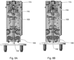
- Fig. 8A shows the transmission element 16 in detail with the holder 20 released.
- Fig. 8B shows the transmission element 16 in a position in which the holder 20 is held by the at least one movable gripping arm 106.
- Fig. 9A shows another example of the transmission element 16 in a retracted position.
- Fig. 9B shows the transmission element from Fig. 9A in an extended position with another example of an alternative release mechanism.
- the release actuator is a release lever 140 which is provided on the transmission element 16 and is movable by a fixed stop 142 in order to release the mandrel 102.
- the release lever 140 bears against the stop when the transmission element 16 is in the extended position.
- the release lever 140 causes a longitudinal movement of the rod, ie the pin 113, which subsequently moves the at least one movable gripping arm 106, for example in order to release the holder 102; or in order to vary the holding force.
- the release lever 140 For the longitudinal movement of the rod, the release lever 140 encompasses an area of the rod which is limited by two stops 144, so that a pivoting movement of the release lever 140 causes a translation of the rod.
- Fig.10 shows another example of the transmission element 16 in an extended position with an alternative release mechanism.
- the release actuator is a release lever 160 which is provided on the transmission element 16 and is movable by a movable stop 162 to release the mandrel 102.
- the movable stop 162 is movable by a separate drive 164 to release the mandrel 102.
- the movable stop 162 can be engaged with the release lever in an area when the transmission element 16 is extended and/or when it is in the extended position.
- the release lever 160 causes a longitudinal displacement of the rod, ie the pin 113. With this movement, the hold of the holder 20 at the front end of the transmission element 16 can be adjusted.
- the movable stop 162 is formed, for example, by a latch 166 which is held at at least two points by pivotable holders 168 and can perform a rotational-translatory movement.
- the movable stop 162 can also be referred to as an actuating/switching element.
- the movement of the movable The stop 162 can be moved, for example, with a worm wheel 172 driven by a motor 170, which has a cam 174 to abut against the movable stop 162 and move it.
- the movable stop 162 extends over a range in the direction of movement of the transmission element 16, it is possible to continuously adjust, i.e. change, the hold of the holder 20 also in intermediate positions of the transmission element 16.
- Fig. 11 shows another example of the transmission element in an extended position with another alternative release mechanism.
- the release actuator is a release lever 180 which is provided on the transmission element 16 and which is movable from a stop 182 of a plurality of stops 184 to release the mandrel.
- the plurality of stops 184 are arranged on a movable latch 166 which is movable perpendicular to the extension direction of the transmission element in the direction of the release lever to bring one of the stops into engagement with the release lever to actuate release levers by movement of the transmission element.
- the movable bolt is designed like a comb and can be moved upwards or sideways, for example, i.e. in Fig. 11 in the x or z direction.
- the comb structure comes into the engagement area of the release lever.
- the closest stop then comes into engagement with the release lever when the transmission element moves and causes the drive to disengage from the transmission element.
- the release lever 180 causes a longitudinal displacement of the rod, i.e. the pin 113. With this movement, the hold of the holder 20 at the front end of the transmission element 16 can be adjusted.
- the stop consisting of a plurality of stops 184 extends over a range in the direction of movement of the transmission element 16, it is possible to adjust, i.e. change, the hold of the holder 20 even in slightly spaced intermediate positions of the transmission element 16.
- the holder has a receptacle, or is designed as a receptacle 24, for temporarily holding the extending free end of the Transmission element 16, wherein the free end has a coupling region 25 which is designed to protrude at least partially into the receptacle.
- Fig. 12 shows an example of the receptacle 24 for temporarily holding an extending free end of the transmission element 16.
- Fig. 13 shows the recording from Fig. 12 in different situations with respect to the free end of the transmission element 16.
- the coupling area 25 is formed at the free chain end with a widening coupling area 302 and the receptacle 24 has at least two movable holding elements 304 in order to at least partially encompass the coupling area 302 so that a releasable positive connection can be created with respect to the holding direction.
- the two movable holding elements 304 act on the coupling area 302 with an adjustable force.
- a first force and a second force can be set with an actuator 306 in order to generate the first holding force and the second holding force.
- the holding elements 304 can be moved in a release direction with the actuator 306 in order to release the holding force.
- the first and second forces are designed such that the receptacle 24 releases the coupling area 302 in an overload situation.
- Fig. 13 shows picture 24 from Fig.5 in different holding states:
- the coupling area 302 is still outside the effective range of the two movable holding elements 304.
- the coupling area 302 is within the effective range of the two movable holding elements 304, which act on the coupling area with the second holding force. In this arrangement, the free end of the chain is held firmly.
- the coupling area 302 is within the effective range of the two movable holding elements 304, but these are only held with the first holding force and the connection can be released, for example to open the vehicle door further by hand.
- the coupling area 302 is detaching from the two movable holding elements 304.
- the receptacle 24 is designed to change from the first holding force to the second holding force in the presentation position and to move the vehicle door into a closed position. In a further example, the receptacle 24 is designed to release the second holding force in the closed position.
- the receptacle 24 is configured to change from the released force to the first holding force in the closed position in order to move the vehicle door into the presentation position, i.e., to open it.
- the movable holding elements 304 are held spring-loaded in a holding direction in order to provide the first holding force.
- a locking of the movable holding elements can be temporarily set by an actuator.
- the holding elements 304 can be moved with the actuator in a release direction against the first and second force in order to release the holding force.
- the second holding force is provided by a spring load, and the actuator is used to attenuate, i.e., counteract, the second holding force to produce the first holding force.
- the actuator is used instead of or in addition to the spring load to generate the first holding force.
- the movable holding elements 304 are designed with a defined elasticity in order to release the coupling area in an overload situation, for example in order to provide anti-pinch protection when tightening. Releasing the coupling area in an overload situation is provided as an option.
- Fig. 14 shows a schematic representation of another example of a receptacle for temporarily holding an extending free end of the transmission element.
- Fig. 15 shows a schematic representation of another example of a receptacle for temporarily holding an extending free end of the transmission element.
- Fig. 14 shows the free chain end with a coupling area 308, which is designed to protrude at least partially into the receptacle 24.
- the receptacle 24 has at least one clamping unit 310 with an actuator 312 in order to hold the coupling area 308 in a clamping manner, so that a releasable frictional connection can be created with respect to the holding direction.
- At least one movably held A bracing element 314 is provided which can be pressed against the coupling region 308 with an adjustable force.
- a first force and a second force are adjustable in order to generate the first holding force and the second holding force.
- the actuator presses the bracing element 312 against the coupling area with a spring element 316.
- the opposite bracing element is, for example, fixed.
- a first double arrow 311 indicates the adjustment of the movable bracing element 312.
- a second double arrow 313 indicates the pressing by the spring element 316.
- the free end of the transmission element with the coupling area projects into a first area 320 of the receptacle and the receptacle has a second area 322 adjacent to the first area into which the coupling area can be moved in an overload situation.
- the design of the second area as an overload coupling function is provided as an option.
- the second area can also be referred to as additional installation space.
- a first arrow 309 indicates the insertion of the coupling area 308 into the first area 320.
- An overload in the closing direction of the vehicle door can be made possible by providing additional installation space in the receiving element. This allows the support element to slip in the event of an overload.
- the second area forms an overload clutch in the closing direction of the vehicle door. In the opening direction, an overload clutch is integrated due to the design-related force-locking connection.
- Fig. 14 shows an example in which the clamping unit has at least one clamping element that is held with an eccentric disk 324 that can be adjusted via an actuator 326 to provide different holding forces.
- the actuator 326 has, for example, a motor that moves the eccentric disk 324 via gear elements, which acts on the spring element 316.
- a first rotational double arrow 315 indicates the adjustment by the eccentric disk 324.
- Fig. 15 shows an example in which the clamping unit has two movably held clamping elements 328, both of which are movable with an adjusting disk 330, which is adjustable via an actuator 332 in order to provide different holding forces.
- the actuator 332 has, for example, a motor, which via gear elements Adjustment disk 330 is moved.
- Two double arrows 317 indicate the adjustment of the movable clamping elements 328.
- a second rotational double arrow 319 indicates the adjustment by the adjustment disk 330.
- Two more attacks 334 are indicated.
- the vehicle door is held on the slope by immersing the support element and then tightening it using a pre-tensioned eccentric disc.
- the vehicle door is held on the slope by immersing the support element and then bracing it with the help of a disk, which enables a translational adjustment of the bracing elements via a drive and a disk and thus creates a force-fitting connection between them.
- Fig. 16 shows an example of a motor vehicle door module 400.
- the motor vehicle door module 400 has an example 402 of the installation module 10 according to one of the preceding examples and a support structure 404 of a motor vehicle door.
- the installation device 12 or the holder 20 is held on the support structure.
- the other of the two, ie the holder 20 or the installation device 12 is designed for attachment to a body area 406 of the motor vehicle.
- the support structure 404 of the motor vehicle door is indicated with a dashed line.
- the bracket 20 is held on the support structure 404 of the vehicle door and the installation device 12 is fastened to the body area 406 of the motor vehicle, for example in the area of the B-pillar or in the lower frame area of the door opening.
- the installation device 12 is held on the support structure 404 of the vehicle door and the bracket 20 is attached to the body area 406 of the motor vehicle.
- the installation module is intended in addition to a vehicle door lock.
Landscapes
- Engineering & Computer Science (AREA)
- Mechanical Engineering (AREA)
- Power-Operated Mechanisms For Wings (AREA)
Description
Die vorliegende Erfindung befasst sich mit dem Öffnen und Schließen von Kraftfahrzeugtüren und befasst sich insbesondere mit einem Aufstellmodul für eine Kraftfahrzeugtür und mit einem Kraftfahrzeugtürmodul.The present invention relates to the opening and closing of motor vehicle doors and, in particular, to a positioning module for a motor vehicle door and to a motor vehicle door module.
Im Zusammenhang mit gestiegenem Nutzerkomfort finden sich Vorschläge für das Öffnen von Kraftfahrzeugtüren mittels eines elektrischen Antriebs. Beispielsweise beschreibt
Eine Aufgabe der vorliegenden Erfindung besteht daher darin, einen Türaufsteller zur Verfügung zu stellen, der einen verbesserten Nutzerkomfort bei kompakter Bauweise ermöglicht.An object of the present invention is therefore to provide a door opener which enables improved user comfort with a compact design.
Diese Aufgabe wird durch den Gegenstand der unabhängigen Ansprüche gelöst. Weitere Beispiele sind in den abhängigen Ansprüchen angegeben. Die im folgenden beschriebenen Aspekte gelten auch für das Aufstellmodul für eine Kraftfahrzeugtür und für das Kraftfahrzeugtürmodul.This object is solved by the subject matter of the independent claims. Further examples are given in the dependent claims. The following The aspects described also apply to the installation module for a motor vehicle door and to the motor vehicle door module.
Gemäß der Erfindung ist ein Aufstellmodul für eine Kraftfahrzeugtür vorgesehen. Das Aufstellmodul weist eine Aufstellvorrichtung auf mit einer Aktuatoreinheit und einem Übertragungselement. Die Aktuatoreinheit ist ausgebildet, das Übertragungselement zwischen einer eingefahrenen Position und einer wenigstens teilweise ausgefahrenen Position zu bewegen. Das Übertragungselement ist ausgebildet, beim Bewegen in die wenigstens teilweise ausgefahrene Position über ein freies Ende des Übertragungselements eine Aufstellkraft für eine Kraftfahrzeugtür von der Aktuatoreinheit zu übertragen. Das Übertragungselement ist translatorisch beweglich ausgebildet. Die Aufstellvorrichtung ist an einem aus der Gruppe von Kraftfahrzeugtür und Karosserie befestigbar, und eine Halterung ist an dem anderen aus der Gruppe von Kraftfahrzeugtür und Karosserie befestigbar ist. Das freie Ende des Übertragungselements ist mit dem anderen aus der Gruppe von Kraftfahrzeugtür und Karosserie über die Halterung temporär verbindbar, um die Kraftfahrzeugtür wenigstens in einer aufgestellten Position lösbar zu halten.According to the invention, a setting-up module for a motor vehicle door is provided. The setting-up module has a setting-up device with an actuator unit and a transmission element. The actuator unit is designed to move the transmission element between a retracted position and an at least partially extended position. The transmission element is designed to transmit a setting-up force for a motor vehicle door from the actuator unit via a free end of the transmission element when moving into the at least partially extended position. The transmission element is designed to be translationally movable. The setting-up device can be fastened to one of the group of motor vehicle door and body, and a holder can be fastened to the other of the group of motor vehicle door and body. The free end of the transmission element can be temporarily connected to the other of the group of motor vehicle door and body via the holder in order to releasably hold the motor vehicle door at least in one set-up position.
Gemäß der Erfindung ist ein lösbarer Haltemechanismus vorgesehen, so dass das Übertragungselement mit der Halterung mittels einer Haltekraft temporär verbindbar ist, die an dem anderen aus der Gruppe von Kraftfahrzeugtür und Karosserie befestigbar ist. Der lösbare Haltemechanismus ist ausgebildet, in der aufgestellten Position der Fahrzeugtür die Haltekraft zu lösen, um die Fahrzeugtür für ein weiteres Öffnen freizugeben.According to the invention, a releasable holding mechanism is provided so that the transmission element can be temporarily connected to the holder by means of a holding force which can be fastened to the other of the group of motor vehicle door and body. The releasable holding mechanism is designed to release the holding force in the raised position of the vehicle door in order to release the vehicle door for further opening.
Gemäß der Erfindung ist das Übertragungselement auch ausgebildet, beim Bewegen von einer ausgefahrenen Position in die eingefahrene Position eine Zuziehkraft für die Kraftfahrzeugtür von der Aktuatoreinheit zu übertragen. Der lösbare Haltemechanismus weist eine einstellbare Haltekraft mit wenigstens einer ersten Haltekraft und einer zweiten Haltekraft auf. Die zweite Haltekraft ist größer als die erste Haltekraft. Die erste Haltekraft ist ausgebildet, um die Kraftfahrzeugtür in der aufgestellten Position gegen ein unbeabsichtigtes weiteres Öffnen der Kraftfahrzeugtür zu halten. Die zweite Haltekraft ist ausgebildet, um ein Zuziehen der Kraftfahrzeugtür zu ermöglichen. Der lösbare Haltemechanismus ist ausgebildet, wenigstens von der ersten Haltekraft zur zweiten Haltekraft zu wechseln und umgekehrt.According to the invention, the transmission element is also designed to transmit a closing force for the motor vehicle door from the actuator unit when moving from an extended position to the retracted position. The releasable holding mechanism has an adjustable holding force with at least a first holding force and a second holding force. The second holding force is greater than the first holding force. The first holding force is designed to hold the motor vehicle door in the raised position against unintentional further opening of the motor vehicle door. The second holding force is designed to enable the motor vehicle door to be closed. The releasable holding mechanism is designed to change at least from the first holding force to the second holding force and vice versa.
Gemäß einem Beispiel ist die Halterung als Dorn mit einem aufgeweiteten Ende ausgebildet. Der lösbare weist Haltemechanismus am freien Ende des Übertragungselements wenigstens einen beweglichen Greifarm auf, um das aufgeweitete Ende des Dorns in Zuziehrichtung zu hintergreifen. In dem Übertragungselements ist ein Betätigungselement für den wenigstens einen beweglichen Greifarm angeordnet, das im Bereich eines dem freien Ende gegenüberliegenden Endes des Übertragungselements mit einem Lösestellglied in Eingriff bringbar ist, um mit dem Lösestellglied den wenigstens einen beweglichen Greifarm in eine Lösestellung für den Dorn zu bewegen.According to one example, the holder is designed as a mandrel with a widened end. The releasable holding mechanism has at least one movable gripping arm at the free end of the transmission element in order to grip behind the widened end of the mandrel in the closing direction. An actuating element for the at least one movable gripping arm is arranged in the transmission element, which can be brought into engagement with a release actuator in the region of an end of the transmission element opposite the free end in order to move the at least one movable gripping arm into a release position for the mandrel with the release actuator.
Gemäß einem Beispiel ist das Lösestellglied ein Lösehebel, der mit einem separaten Aktuator bewegbar ist, um den Dorn freizugeben. Der Lösehebel ist mit dem Betätigungselement in Eingriff bringbar, wenn das Übertragungselement in der ausgefahrenen Position ist.According to one example, the release actuator is a release lever that is movable with a separate actuator to release the mandrel. The release lever is engageable with the actuating element when the transmission element is in the extended position.
Gemäß einem Beispiel ist das Lösestellglied ein Lösehebel ist, der an dem Übertragungselement vorgesehen ist und durch einen feststehenden Anschlag bewegbar ist, um den Dorn freizugeben. Der Lösehebel liegt an dem Anschlag an, wenn das Übertragungselement in der ausgefahrenen Position ist.According to one example, the release actuator is a release lever provided on the transmission element and movable through a fixed stop to release the mandrel. The release lever abuts the stop when the transmission element is in the extended position.
Gemäß einem Beispiel ist das Lösestellglied ein Lösehebel, der an dem Übertragungselement vorgesehen ist und durch einen beweglichen Anschlag bewegbar ist, um den Dorn freizugeben. Der bewegliche Anschlag ist mit einem separaten Antrieb bewegbar, um den Dorn freizugeben. Der bewegliche Anschlag ist mit dem Lösehebel in einem Bereich in Eingriff bringbar, wenn das Übertragungselement ausgefahren wird und wenn es sich in der ausgefahrenen Position befindet.According to one example, the release actuator is a release lever provided on the transmission element and movable by a movable stop to release the mandrel. The movable stop is movable with a separate drive to release the mandrel. The movable stop is engageable with the release lever in a region when the transmission element is extended and when it is in the extended position.
Gemäß einem Beispiel ist das Lösestellglied ein Lösehebel, der an dem Übertragungselement vorgesehen ist und der von einem Anschlag aus einer Vielzahl von Anschlägen bewegbar ist, um den Dorn. Die Vielzahl von Anschlägen an einem beweglichen Riegel ist angeordnet. Der Riegel ist senkrecht zur Ausfahrrichtung des Übertragungselements in Richtung des Lösehebels bewegbar, um einen der Anschläge in Eingriff mit dem Lösehebel zu bringen, um durch Bewegung des Übertragungselements Lösehebel zu betätigen.According to one example, the release actuator is a release lever provided on the transmission element and movable from one of a plurality of stops to the mandrel. The plurality of stops are arranged on a movable latch. The latch is movable perpendicular to the extension direction of the transmission element in the direction of the release lever to bring one of the stops into engagement with the release lever to actuate the release lever by movement of the transmission element.
Gemäß einem Beispiel weist die Halterung eine Aufnahme auf, bzw. ist als Aufnahme ausgebildet, zum temporären Halten des ausfahrenden freien Endes des Übertragungselements, wobei das freie Ende einen Kupplungsbereich aufweist, der ausgebildet ist, wenigstens teilweise in die Aufnahme hineinzuragen.According to one example, the holder has a receptacle, or is designed as a receptacle, for temporarily holding the extending free end of the transmission element, wherein the free end has a coupling region which is designed to protrude at least partially into the receptacle.
Die Aufnahme weist wenigstens eine Verspanneinheit mit einem Stellglied auf, um den Kupplungsbereich klemmend zu halten, so dass bezogen auf die Halterichtung eine lösbare reibschlüssige Verbindung erzeugbar ist. Wenigstens ein beweglich gehaltenes Verspannelement ist vorgesehen, das mit einer einstellbaren Kraft gegen den Kupplungsbereich anpressbar ist. Eine erste Kraft und eine zweite Kraft sind einstellbar, um die erste Haltekraft und die zweite Haltekraft zu erzeugen.The receptacle has at least one clamping unit with an actuator to hold the coupling area in a clamping manner so that a releasable frictional connection can be created in relation to the holding direction. At least one movably held clamping element is provided which can be pressed against the coupling area with an adjustable force. A first force and a second force are adjustable to generate the first holding force and the second holding force.
Gemäß einem Beispiel ragt in einem Haltezustand das freie Ende des Übertragungselements mit dem Kupplungsbereich in einen ersten Bereich der Aufnahme hinein und die Aufnahme weist im Anschluss an den ersten Bereich einen zweiten Bereich auf, in den der Kupplungsbereich bei einer Überlastsituation verschiebbar ist.According to one example, in a holding state, the free end of the transmission element with the coupling region projects into a first region of the receptacle and the receptacle has a second region adjacent to the first region into which the coupling region can be displaced in the event of an overload situation.
In einer Option weist die Verspanneinheit wenigstens ein Verspannelement auf, das mit einer Exzenterscheibe gehalten ist, die über ein Stellglied einstellbar ist, um verschiedene Haltekräfte zur Verfügung zu stellen.In one option, the clamping unit has at least one clamping element which is held with an eccentric disc which is adjustable via an actuator to provide different holding forces.
In einer anderen Option weist die Verspanneinheit zwei beweglich gehaltene Verspannelemente auf, die beide mit einer Verstellscheibe bewegbar sind, die über ein Stellglied einstellbar ist, um verschiedene Haltekräfte zur Verfügung zu stellen.In another option, the clamping unit has two movably held clamping elements, both of which are movable with an adjusting disk that is adjustable via an actuator to provide different holding forces.
Gemäß einem Beispiel ist das freie Ende des Übertragungselements mit einem sich aufweitenden Kupplungsbereich ausgebildet und wobei die Aufnahme weist wenigstens zwei bewegliche Halteelemente auf, um den Kupplungsbereich wenigstens teilweise zu umgreifen, so dass bezogen auf die Halterichtung eine lösbare formschlüssige Verbindung erzeugbar ist. Die zwei beweglichen Halteelemente wirken mit einer einstellbaren Kraft auf den Kupplungsbereich. Mit einem Stellglied sind eine erste Kraft und eine zweite Kraft einstellbar, um die erste Haltekraft und die zweite Haltekraft zu erzeugen. Die Halteelemente sind mit dem Stellglied in einer Löserichtung bewegbar, um die Haltekraft zu lösen. Die erste und die zweite Kraft sind so ausgebildet, dass die Aufnahme der Kupplungsbereich bei einer Überlastsituation frei gibt.According to one example, the free end of the transmission element is designed with a widening coupling region, and the receptacle has at least two movable holding elements to at least partially encompass the coupling region, so that a releasable, positive connection can be created with respect to the holding direction. The two movable holding elements act on the coupling region with an adjustable force. A first force and a second force can be adjusted with an actuator in order to generate the first holding force and the second holding force. The holding elements can be moved with the actuator in a release direction in order to release the holding force. The first and second forces are designed such that the receptacle releases the coupling region in an overload situation.
Gemäß der Erfindung ist auch ein Kraftfahrzeugtürmodul vorgesehen. Das Kraftfahrzeugtürmodul weist ein Aufstellmodul nach einem der vorhergehenden Beispiele und eine Tragstruktur einer Kraftfahrzeugtür auf. Eines aus der Gruppe von der Aufstellvorrichtung und der Halterung ist an der Tragstruktur gehalten. Das andere aus der Gruppe von der Aufstellvorrichtung und der Halterung ist zur Befestigung an einem Karosseriebereich des Kraftfahrzeugs ausgebildet.According to the invention, a motor vehicle door module is also provided. The motor vehicle door module has a mounting module according to one of the preceding examples and a support structure of a motor vehicle door. One of the group of the mounting device and the holder is held on the support structure. The other of the group of the mounting device and the holder is designed for fastening to a body region of the motor vehicle.
Der Aktuator ist beispielsweise ein elektrischer Aktuator, beispielsweise als linear betreibbarer elektromagnetischer Aktuator (elektromagnetisches Stellglied) oder als rotatorisch betreibbarer elektromagnetischer Aktuator (Elektromotor).The actuator is, for example, an electrical actuator, for example as a linearly operable electromagnetic actuator (electromagnetic actuator) or as a rotary-operable electromagnetic actuator (electric motor).
Gemäß einem Aspekt der Erfindung ist ein Aufsteller vorgesehen, der die Fahrzeugtür in aufgestelltem Zustand auch lösbar halten kann.According to one aspect of the invention, a stand is provided which can also releasably hold the vehicle door in the open state.
Nachfolgend wird anhand der beigefügten Zeichnungen näher auf Ausführungsbeispiele der Erfindung eingegangen.
- Fig. 1
- zeigt ein Beispiel eines Aufstellmoduls für eine Kraftfahrzeugtür in einer schematischen Skizze.
- Fig. 2
- zeigt ein Beispiel eines Aufstellmoduls für eine Kraftfahrzeugtür in einer perspektivischen Ansicht.
- Fig. 3
- zeigt das Aufstellmodul aus
Fig. 2 mit ausgefahrenem Übertragungselement. - Fig. 4
- zeigt das Aufstellmodul aus
Fig. 2 und Fig. 3A in verschiedenen Stellungen während des Ablaufs eines Öffnungsvorgangs einer Kraftfahrzeugtür. - Fig. 5
- zeigt das Aufstellmodul aus
Fig. 2 und Fig. 3A in verschiedenen Stellungen während des Ablaufs eines Zuzieh- bzw. Schließvorgangs einer Kraftfahrzeugtür. - Fig. 6
- zeigt das Aufstellmodul aus
Fig. 2 im Detail in einer eingefahrenen Position. - Fig. 7
- zeigt das Aufstellmodul aus
Fig. 6 in einer ausgefahrenen Position mit gehaltener Fahrzeugtür und mit einem Lösemechanismus. - Fig. 8A
- zeigt ein Beispiel des Übertragungselements im Detail mit gelöster Halterung der Fahrzeugtür.
- Fig. 8B
- zeigt das Übertragungselement aus
Fig. 8A mit gehaltener Fahrzeugtür. - Fig. 9A
- zeigt ein weiteres Beispiel des Übertragungselements in einer eingefahrenen Position.
- Fig. 9B
- zeigt das Übertragungselement aus
Fig. 9A in einer ausgefahrenen Position mit einem weiteren Beispiel für einen alternativen Lösemechanismus. - Fig. 10
- zeigt ein weiteres Beispiel des Übertragungselements in einer ausgefahrenen Position mit einem alternativen Lösemechanismus.
- Fig. 11
- zeigt ein weiteres Beispiel des Übertragungselements in einer ausgefahrenen Position mit einem weiteren alternativen Lösemechanismus.
- Fig. 12
- zeigt ein alternatives Beispiel einer Aufnahme zum temporären Halten eines ausfahrenden freien Endes des Übertragungselements.
- Fig. 13
- zeigt die Aufnahme aus
Fig. 12 in verschiedenen Situationen in Bezug auf das freie Ende des Übertragungselements. - Fig. 14
- zeigt eine schematische Darstellung eines weiteren Beispiels einer Aufnahme zum temporären Halten eines ausfahrenden freien Endes des Übertragungselements.
- Fig. 15
- zeigt eine schematische Darstellung eines anderen Beispiels einer Aufnahme zum temporären Halten eines ausfahrenden freien Endes des Übertragungselements.
- Fig. 16
- zeigt ein Beispiel eines Kraftfahrzeugtürmoduls.
- Fig. 17
- zeigt ein Beispiel eines nicht beanspruchten
- Fig.1
- shows an example of a mounting module for a motor vehicle door in a schematic sketch.
- Fig.2
- shows an example of a mounting module for a motor vehicle door in a perspective view.
- Fig.3
- shows the installation module
Fig.2 with extended transmission element. - Fig.4
- shows the installation module
Fig.2 and Fig. 3A in different positions during the opening process of a motor vehicle door. - Fig.5
- shows the installation module
Fig.2 and Fig. 3A in different positions during the closing or closing process of a motor vehicle door. - Fig.6
- shows the installation module
Fig.2 in detail in a retracted position. - Fig.7
- shows the installation module
Fig.6 in an extended position with the vehicle door held and with a release mechanism. - Fig. 8A
- shows an example of the transmission element in detail with the vehicle door bracket removed.
- Fig. 8B
- shows the transmission element from
Fig. 8A with the vehicle door held shut. - Fig. 9A
- shows another example of the transmission element in a retracted position.
- Fig. 9B
- shows the transmission element from
Fig. 9A in an extended position with another example of an alternative release mechanism. - Fig.10
- shows another example of the transmission element in an extended position with an alternative release mechanism.
- Fig. 11
- shows another example of the transmission element in an extended position with another alternative release mechanism.
- Fig. 12
- shows an alternative example of a holder for temporarily holding an extending free end of the transmission element.
- Fig. 13
- shows the recording from
Fig. 12 in different situations with respect to the free end of the transmission element. - Fig. 14
- shows a schematic representation of another example of a receptacle for temporarily holding an extending free end of the transmission element.
- Fig. 15
- shows a schematic representation of another example of a receptacle for temporarily holding an extending free end of the transmission element.
- Fig. 16
- shows an example of a motor vehicle door module.
- Fig. 17
- shows an example of an unclaimed
Verfahrens zum Bewegen einer Kraftfahrzeugtür.Method for moving a motor vehicle door.
In
In einem Beispiel ist das Übertragungselement als translatorisch beweglicher Riegel ausgebildet, der in der ausgefahrenen Position mit einem ausgefahrenen Bereich in einer Ausfahrrichtung angeordnet ist, um in dieser Position mit einem freien Ende die Aufstellkraft in eine Aufstellrichtung zu übertragen.In one example, the transmission element is designed as a translationally movable latch which, in the extended position, is arranged with an extended region in an extension direction in order to transmit the setting-up force in an setting-up direction with a free end in this position.
Die eingefahrene Position kann auch als erste Position, Einfahrposition oder Verstauposition bezeichnet werden. Die ausgefahrene Position kann auch als zweite Position, Aufstellposition, Ausfahrposition oder Ausstellposition bezeichnet werden. Die ausgefahrene Position kann auch als Präsentationsposition bezeichnet werden.The retracted position may also be referred to as the first position, retracted position or stowed position. The extended position may also be referred to as the second position, deployed position, extended position or displayed position. The extended position may also be referred to as the presentation position.
Die Präsentationsposition kann auch als Spaltposition oder Greifposition bezeichnet werden, in der ein Nutzer die Fahrzeugtür manuell in eine weiter, zum Beispiel vollständig geöffnete Position zu bewegen. Dies bietet sich zum Beispiel bei Fahrzeugtüren an, die keinen äußeren Türgriff aufweisen.The presentation position can also be referred to as the gap position or grip position, in which a user can manually move the vehicle door to a wider, for example fully open, position. This is useful, for example, for vehicle doors that do not have an external door handle.
In einem Beispiel ist das Übertragungselement 16 als translatorisch beweglicher Riegel 56 ausgebildet, der in der ausgefahrenen Position mit einem ausgefahrenen Bereich 58 (siehe Fig. 3A) in einer Ausfahrrichtung angeordnet ist, um in dieser Position mit einem freien Ende 60 die Aufstellkraft in eine Aufstellrichtung zu übertragen.In one example, the
In
In einer Option ist ein lösbarer Haltemechanismus 62 vorgesehen, so dass das Übertragungselement 16 mit der Halterung 20 mittels einer Haltekraft temporär verbindbar ist, die an dem anderen aus der Gruppe von Kraftfahrzeugtür und Karosserie befestigbar ist. Der lösbare Haltemechanismus ist ausgebildet, in der aufgestellten Position der Fahrzeugtür die Haltekraft zu lösen, um die Fahrzeugtür für ein weiteres Öffnen freizugeben.In one option, a
Das Übertragungselement 16 ist auch ausgebildet, beim Bewegen von einer ausgefahrenen Position in die eingefahrene Position eine Zuziehkraft für die Kraftfahrzeugtür von der Aktuatoreinheit 14 zu übertragen. Der lösbare Haltemechanismus 62 weist eine einstellbare Haltekraft mit wenigstens einer ersten Haltekraft und einer zweiten Haltekraft auf. Die zweite Haltekraft ist größer als die erste Haltekraft. Die erste Haltekraft ist ausgebildet, um die Kraftfahrzeugtür in der aufgestellten Position gegen ein unbeabsichtigtes weiteres Öffnen der Kraftfahrzeugtür zu halten. Die zweite Haltekraft ist ausgebildet, um ein Zuziehen der Kraftfahrzeugtür zu ermöglichen. Der lösbare Haltemechanismus 62 ist ausgebildet, wenigstens von der ersten Haltekraft zur zweiten Haltekraft zu wechseln und umgekehrt.The
Das Lösen der Haltekraft ist als Option vorgesehen.Releasing the holding force is provided as an option.
In einer Option ist vorgesehen, dass das Zuziehen der Kraftfahrzeugtür ein Bewegen der Kraftfahrzeugtür in eine Vorrastposition eines Türschlosses der Kraftfahrzeugtür und ein weiteres Bewegen und dabei Andrücken der Fahrzeugtür gegen eine Türdichtung und Bewegen der Kraftfahrzeugtür in eine Hauptrastposition des Türschlosses umfasst. Die Einstellbarkeit der ersten Haltekraft und der zweiten Haltekraft ist als Option vorgesehen.One option provides that closing the motor vehicle door involves moving the motor vehicle door into a pre-latching position of a door lock of the motor vehicle door and then moving it further, thereby pressing the vehicle door against a door seal and moving the motor vehicle door into a main latching position of the door lock. The adjustability of the first holding force and the second holding force is provided as an option.
Der lösbare Haltemechanismus 62 weist am freien Ende des Übertragungselements 16 wenigstens einen beweglichen Greifarm 106 auf, um das aufgeweitete Ende 104 des Dorns 102 in Zuziehrichtung zu hintergreifen. In dem Übertragungselements 16 ist ein Betätigungselement 108 für den wenigstens einen beweglichen Greifarm 106 angeordnet ist, das im Bereich eines dem freien Ende gegenüberliegenden Endes 110 des Übertragungselements 16 mit einem Lösestellglied 112 in Eingriff bringbar ist, um mit dem Lösestellglied 112 den wenigstens einen beweglichen Greifarm 106 in eine Lösestellung für den Dorn 102 zu bewegen.The
In einem Beispiel ist vorgesehen, dass das Lösestellglied ein Lösehebel 114 ist, der mit einem separaten Aktuator bewegbar ist, um den Dorn 102 freizugeben. Der Lösehebel 114 kann mit dem Betätigungselement 108 in Eingriff gebracht werden, wenn das Übertragungselement 16 in der ausgefahrenen Position ist.In one example, the release actuator is provided as a
Das Betätigungselement 108 ist als Option vorgesehen. In einer Alternative ist ein Stellglied für den wenigstens einen beweglichen Greifarm 106 vorgesehen, das in dem Übertragungselement 16 angeordnet ist, beispielsweise im Bereich des ausfahrenden Endes.The
In dem gezeigten Beispiel weist der lösbare Haltemechanismus zwei bewegliche Greifarme 106 auf, die das aufgeweitete Ende des Dorns von zwei Seiten umgreifen.In the example shown, the releasable holding mechanism has two movable
Das Lösestellglied 112 ist zum Beispiel als längsverlaufender Stab oder Pin 113 ausgebildet, der an seinem hinteren Ende einen Betätigungsvorsprung 116 hat. Der Pin 113 ist an seinem hinteren Ende in einer Aufnahme 115 gehalten, die in der eingeschobenen Position des Pins 113 einen Anschlag bildet. Die Aufnahme 115 bildet eine Führung für das Ende des Pins 113.The
In ausgefahrenem Zustand des Übertragungselements 16 befindet sich der Betätigungsvorsprung 114 in einem Eingriffsbereich eines Steuerhebels 118, der von einem zweiten Antrieb 120 bewegt wird. Der Steuerhebel 116 ist schwenkbar gelagert und kann über einen Getriebehebel 122 bewegt werden. Der Getriebehebel 122 wird zum Beispiel von einer drehbar vom zweiten Antrieb 120 angetriebenen Scheibe verschwenkt. Durch Eingriff des Steuerhebels 118 kann der Betätigungsvorsprung 116 und damit das Lösestellglied 112 in Längsrichtung bewegt werden, um den wenigstens einen beweglichen Greifarm 106 zu bewegen. Zum Beispiel kann der wenigstens eine bewegliche Greifarm 106 in eine gelöste Stellung bewegt werden, um die Halterung freizugeben.In the extended state of the
Für die längsgerichtete Bewegung des Stabs umgreift der Lösehebel 140 einen Bereich des Stabs, der durch zwei Anschläge 144 begrenzt ist, so dass eine Schwenkbewegung des Lösehebels 140 eine Translation des Stabs bewirkt.For the longitudinal movement of the rod, the
Der bewegliche Anschlag 162 wird beispielsweise durch einen Riegel 166 gebildet, der an wenigstens zwei Punkten mit verschwenkbaren Halterungen 168 gehalten ist und eine rotatorisch-translatorische Bewegung ausführen kann. Der bewegliche Anschlag 162 kann auch als Stell-/Schaltelement bezeichnet werden. Die Bewegung des beweglichen Anschlags 162 kann beispielsweise mit einem von einem Motor 170 angetriebenen Schneckenrad 172 erfolgen, das einen Nocken 174 aufweist, um an dem beweglichen Anschlag 162 anzuliegen und diesen zu bewegen.The
Da sich der bewegliche Anschlag 162 über einen Bereich in der Richtung der Bewegung des Übertragungselements 16 erstreckt, ist es möglich, den Halt der Halterung 20 auch kontinuierlich in Zwischenpositionen des Übertragungselements 16 einzustellen, d.h. zu ändern.Since the
Der bewegliche Riegel ist kammartig ausgeführt und beispielsweise nach oben oder seitlich verschieblich gelagert, d.h. in
Der Lösehebel 180 bewirkt eine längsgerichtete Verschiebung des Stabs, d.h. des Pins 113. Mit dieser Bewegung kann der Halt der Halterung 20 am vorderen Ende des Übertragungselements 16 eingestellt werden.The
Da sich der Anschlag aus einer Vielzahl von Anschlägen 184 über einen Bereich in der Richtung der Bewegung des Übertragungselements 16 erstreckt, ist es möglich, den Halt der Halterung 20 auch in geringfügig beabstandeten Zwischenpositionen des Übertragungselements 16 einzustellen, d.h. zu ändern.Since the stop consisting of a plurality of
Gemäß einem Beispiel weist die Halterung eine Aufnahme auf, bzw. ist als Aufnahme 24 ausgebildet, zum temporären Halten des ausfahrenden freien Endes des Übertragungselements 16, wobei das freie Ende einen Kupplungsbereich 25 aufweist, der ausgebildet ist, wenigstens teilweise in die Aufnahme hineinzuragen.According to one example, the holder has a receptacle, or is designed as a
In dem Beispiel aus
In einem Beispiel ist die Aufnahme 24 ausgebildet, in der Präsentationsposition von der ersten Haltekraft zur zweiten Haltekraft zu wechseln und die Fahrzeugtür in eine geschlossene Position zuzuziehen. In einem weiteren Beispiel ist die Aufnahme 24 ausgebildet, in der geschlossenen Position die zweite Haltekraft zu lösen.In one example, the
In einem Beispiel ist die Aufnahme 24 ausgebildet, in der geschlossenen Position von der gelösten Kraft in die erste Haltekraft zu wechseln, um die Fahrzeugtür in die Präsentationsposition zu bewegen, d.h. aufzustellen.In one example, the
Beispielsweise sind die beweglichen Halteelemente 304 in einer Halterichtung federbelastet gehalten, um die erste Haltekraft zur Verfügung zu stellen. Für die zweite Haltekraft ist eine Arretierung der beweglichen Halteelemente durch ein Stellglied temporär einstellbar. Die Halteelemente 304 sind mit dem Stellglied in einer Löserichtung entgegen der ersten und zweiten Kraft bewegbar, um die Haltekraft zu lösen.For example, the
In einem anderen Beispiel wird die zweite Haltekraft durch eine Federbelastung zur Verfügung gestellt, und das Stellglied wird verwendet, um zur Erzeugung der ersten Haltekraft die zweite Haltekraft abzuschwächen, d.h. dieser entgegen zu wirken.In another example, the second holding force is provided by a spring load, and the actuator is used to attenuate, i.e., counteract, the second holding force to produce the first holding force.
In einem Beispiel wird für die erste Haltekraft statt oder in Ergänzung zu der Federbelastung das Stellglied verwendet, um die erste Haltekraft zu erzeugen.In one example, the actuator is used instead of or in addition to the spring load to generate the first holding force.
In einem Beispiel ist vorgesehen, dass die beweglichen Halteelemente 304 mit einer definierten Elastizität ausgebildet sind, um bei einer Überlastsituation den Kupplungsbereich freizugeben, beispielsweise, um beim Zuziehen einen Einklemmschutz zur Verfügung zu stellen. Das Freigeben des Kupplungsbereichs bei einer Überlastsituation ist als Option vorgesehen.In one example, it is provided that the
In einem Beispiel presst das Stellglied das Verspannelement 312 mit einem Federelement 316 gegen den Kupplungsbereich an. Das gegenüberliegende Verspannelement ist zum Beispiel fest. Ein erster Doppelpfeil 311 deutet das Einstellen des beweglichen Verspannelements 312 an. Ein zweiter Doppelpfeil 313 deutet das Anpressen durch das Federelement 316 an.In one example, the actuator presses the bracing
In einem Beispiel ist vorgesehen, dass in einem Haltezustand das freie Ende des Übertragungselements mit dem Kupplungsbereich in einen ersten Bereich 320 der Aufnahme hineinragt und die Aufnahme im Anschluss an den ersten Bereich einen zweiten Bereich 322 aufweist, in den der Kupplungsbereich bei einer Überlastsituation verschiebbar ist. Die Ausbildung des zweiten Bereichs als Überlastkupplungsfunktion ist als Option vorgesehen. Der zweite Bereich kann auch als Mehrbauraum bezeichnet werden. Ein erster Pfeil 309 deutet das Einführen des Kupplungsbereichs 308 in den ersten Bereich 320 an.In one example, it is provided that in a holding state the free end of the transmission element with the coupling area projects into a
Eine Überlast in Schließrichtung der Fahrzeugtür kann durch vorgesehenen Mehrbauraum im Aufnahmeelement ermöglicht werden. Dadurch wird ein Durchrutschen des Aufstellelements bei Überlast ermöglicht. Der zweite Bereich bildet eine Überlastkupplung in Schließrichtung der Fahrzeugtür. In Öffnungsrichtung ist durch die bauartbedingte kraftschlüssige Verbindung eine Überlastkupplung integriert.An overload in the closing direction of the vehicle door can be made possible by providing additional installation space in the receiving element. This allows the support element to slip in the event of an overload. The second area forms an overload clutch in the closing direction of the vehicle door. In the opening direction, an overload clutch is integrated due to the design-related force-locking connection.
In einem Beispiel ist vorgesehen, dass die Fahrzeugtür am Hang durch das Eintauchen des Aufstellelements und das anschließende Verspannen mit Hilfe einer vorgespannten Exzenterscheibe gehalten wird.In one example, the vehicle door is held on the slope by immersing the support element and then tightening it using a pre-tensioned eccentric disc.
In einem Beispiel ist vorgesehen, dass die Fahrzeugtür am Hang durch das Eintauchen des Aufstellelements und das anschließende Verspannen mit Hilfe einer Scheibe gehalten wird, welche über einen Antrieb und einer Scheibe eine translatorische Verstellung der Verspannelemente ermöglicht und so eine kraftschlüssige Verbindung zwischen diesen herstellt.In one example, it is provided that the vehicle door is held on the slope by immersing the support element and then bracing it with the help of a disk, which enables a translational adjustment of the bracing elements via a drive and a disk and thus creates a force-fitting connection between them.
In dem gezeigten Beispiel ist die Halterung 20 an der Tragstruktur 404 der Fahrzeugtür gehalten und die Aufstellvorrichtung 12 ist an dem Karosseriebereich 406 des Kraftfahrzeugs befestigt, zum Beispiel im Bereich der B-Säule oder im unteren Rahmenbereich der Türöffnung.In the example shown, the
In einem anderen Beispiel ist die Aufstellvorrichtung 12 an der Tragstruktur 404 der Fahrzeugtür gehalten und die Halterung 20 ist an dem Karosseriebereich 406 des Kraftfahrzeugs befestigt.In another example, the
Das Aufstellmodul ist zusätzlich zu einem Kraftfahrzeugtürschloss vorgesehen.The installation module is intended in addition to a vehicle door lock.
- In einem ersten
Schritt 502, auch als Schritt a) bezeichnet, wird eine Antriebskraft für die Bewegung einer Kraftfahrzeugtür erzeugt. - In einem zweiten
Schritt 504, auch als Schritt b) bezeichnet, wird die Antriebskraft auf ein als translatorisch bewegliches Übertragungselement übertragen, wobei das Übertragungselement zwischen einer eingefahrenen Position und einer wenigstens teilweise ausgefahrenen Position bewegt werden kann. - In einem dritten
Schritt 506, auch als Schritt c) bezeichnet, erfolgt ein Ein- oder Ausfahren des Übertragungselements. - In einem vierten
Schritt 508, auch als Schritt d) bezeichnet, wird die Bewegungskraft zwischen der Kraftfahrzeugtür und einer Türhaltestruktur aufgebracht. - In
einem fünften Schritt 510, auch als Schritt e) bezeichnet, wird die Kraftfahrzeugtür in Relation zu der Türhaltestruktur bewegt, wobei die Kraftfahrzeugtür wenigstens in einer aufgestellten Position lösbar gehalten ist.
- In a
first step 502, also referred to as step a), a driving force is generated for the movement of a motor vehicle door. - In a
second step 504, also referred to as step b), the driving force is transmitted to a translationally movable transmission element, wherein the transmission element can be moved between a retracted position and an at least partially extended position. - In a
third step 506, also referred to as step c), the transmission element is extended or retracted. - In a
fourth step 508, also referred to as step d), the moving force is applied between the motor vehicle door and a door retaining structure. - In a
fifth step 510, also referred to as step e), the motor vehicle door is moved in relation to the door holding structure, wherein the motor vehicle door is releasably held at least in an upright position.
Die Schritte erfolgen zum Beispiel nahezu zeitgleich.For example, the steps occur almost simultaneously.
Die oberhalb beschriebenen Ausführungsbeispiele können in unterschiedlicher Art und Weise kombiniert werden.The embodiments described above can be combined in different ways.
Ergänzend ist darauf hinzuweisen, dass "umfassend" keine anderen Elemente ausschließt und "eine" oder "ein" keine Vielzahl ausschließt. Ferner sei darauf hingewiesen, dass Merkmale, die mit Verweis auf eines der obigen Ausführungsbeispiele beschrieben worden sind, auch in Kombination mit anderen Merkmalen anderer oben beschriebener Ausführungsbeispiele verwendet werden können. Bezugszeichen in den Ansprüchen sind nicht als Einschränkung anzusehen.In addition, it should be noted that "comprising" does not exclude other elements and "a" or "an" does not exclude a plurality. It should also be noted that features that have been described with reference to one of the above embodiments can also be used in combination with other features of other embodiments described above. Reference signs in the claims are not to be regarded as a limitation.
Claims (10)
- An opening module (10) for a motor vehicle door, the opening module comprising an opening device (12) with:- an actuator unit (14); and- a transmission element (16);the actuator unit (14) being configured to move the transmission element (16) between a retracted position (P1) and an at least partially extended position (P2);wherein the transmission element (16) is configured, when moving into the at least partially extended position (P2), to transmit an opening force for a motor vehicle door from the actuator unit (14) via a free end (18) of the transmission element (16);wherein the transmission element (16) is configured to be movable in translation;wherein the opening device (12) is attachable to one of the motor vehicle door and body, and a holder (20) is attachable to the other of the motor vehicle door and body; andwherein the free end of the transmission element (16) is temporarily connectable to the other of the motor vehicle door and body via the holder (20) to releasably retain the motor vehicle door in at least an opened position;wherein a releasable holding mechanism (62) is provided so that the transmission element (16) is temporarily connectable to the holder by means of a holding force attachable to the other of the group of motor vehicle door and body group; wherein the releasable holding mechanism (62) is configured to release the holding force in the opened position of the vehicle door to release the vehicle door for further opening; andwherein the transmission element (16) is configured, when moving from an extended position (P2) to the retracted position (P1), to transmit a closing force for the motor vehicle door from the actuator unit (14);wherein the releasable holding mechanism (62) is configured to provide an adjustable holding force with at least a first holding force and a second holding force; wherein the second holding force is greater than the first holding force; wherein the first holding force is configured to hold the motor vehicle door in the opened position against unintentional further opening of the motor vehicle door; wherein the second holding force is configured to enable the motor vehicle door to be pulled closed; and wherein the releasable holding mechanism is configured to switch at least from the first holding force to the second holding force and vice versa.
- Opening module (10) according to claim 1, wherein the holder (20) is configured as a mandrel (102) with a widened end (104);wherein the releasable holding mechanism (62) comprises at least one movable gripping arm (106) at the free end of the transmission element (16) in order to grip behind the widened end (104) of the mandrel (102) in the pulling direction; andwherein in the transmission element (16) an operating element (108) for the at least one movable gripping arm is arranged, which operating element, in the region of an end of the transmission element (16) opposite the free end, is bringable into engagement with a release control member (112), in order to move the at least one movable gripping arm into a release position for the mandrel by means of the release control member.
- Opening module (10) of claim 2, wherein the release control member (112) is a release lever (114) movable with a separate actuator to clear the mandrel (102); and
wherein the release lever is bringable into engagement with the operating element (108) when the transmission element (16) is in the extended position (P2). - Opening module (10) according to claim 2, wherein the release control member (112) is a release lever (114) provided on the transmission element (16) and movable by a fixed stopper to clear the mandrel (102); and
wherein the release lever abuts the stopper when the transmission element (16) is in the extended position (P2). - Opening module (10) according to claim 2, wherein the release control member (112) is a release lever (114) provided on the transmission element (16) and movable by a movable stopper (162) to clear the mandrel (102); andwherein the movable stopper is movable by a separate drive to clear the mandrel;wherein the movable stopper is engageable with the release lever in a region when the transmission element (16) is extended and when it is in the extended position (P2).
- Opening module (10) according to claim 2, wherein said release control member (112) is a release lever (114) provided on the transmission element (16) and is movable from a stopper of a plurality of stoppers to clear said mandrel (102);
wherein said plurality of stoppers are arranged on a movable latch (166) which is movable perpendicular to the extending direction of said transmission element (16) toward said release lever to bring one of the stoppers in engagement with the release lever to actuate the release lever by moving said transmission element (16). - Opening module (10) according to claim 1, wherein the free end of the transmission element (16) is configured with a widening coupling region (302) and wherein the receptacle comprises at least two movable retaining elements (304) to at least partially embrace the coupling region, so that a releasable positive connection is generatable with respect to the holder direction;wherein the two movable retaining elements act on the coupling region with an adjustable force;wherein a first force and a second force are adjustable with a control member (306) in order to generate the first holding force and the second holding force;wherein the retaining elements are movable with the control member in a release direction to release the holding force; andwherein the first and second forces are configured to clear the receptacle of the coupling region in an overload situation.
- Opening module (10) according to claim 1, wherein the holder (20) comprises a receptacle (24) for temporarily holding the extending free end of the transmission element (16), wherein the free end comprises a coupling region (125) which is configured to project at least partially into the receptacle;wherein the receptacle has at least one tensioning unit (310) with a control member (312) in order to hold the coupling region in a clamping manner, so that a releasable frictional connection is generatable with respect to the holder direction;wherein at least one movably held tensioning element (314) is provided, which is pressable against the coupling region with an adjustable force; andwherein a first force and a second force are adjustable in order to generate the first holding force and the second holding force.
- Opening module (10) according to claim 8,
wherein in a holding state the free end of the transmission element (16) with the coupling region (25) projects into a first region of the receptacle (24) and the receptacle comprises a second region (322) adjoining the first region (320), into which the coupling region is displaceable in an overload situation; and
wherein the tensioning unit:i) comprises at least one tensioning element which is held with an eccentric disk (324) which is adjustable via a control member (326) in order to provide different holding forces; orii) comprises two movably held tensioning elements (328) which are both movable with an adjusting disk (330) which is adjustable via a control member (332) in order to provide different holding forces. - A motor vehicle door module (400), comprising:- an opening module (10) according to any one of the preceding claims; and- a support structure (404) of a motor vehicle door;wherein one of the group of the opening device (12) and the holder (20) is held at the support structure; andwherein the other of the group of the opening device and the holder is configured to be attached to a body region (406) of the motor vehicle.
Applications Claiming Priority (1)
| Application Number | Priority Date | Filing Date | Title |
|---|---|---|---|
| DE102020113727.3A DE102020113727A1 (en) | 2020-05-20 | 2020-05-20 | Door stand with detachable bracket |
Publications (2)
| Publication Number | Publication Date |
|---|---|
| EP3913181A1 EP3913181A1 (en) | 2021-11-24 |
| EP3913181B1 true EP3913181B1 (en) | 2024-05-08 |
Family
ID=76034556
Family Applications (1)
| Application Number | Title | Priority Date | Filing Date |
|---|---|---|---|
| EP21175040.1A Active EP3913181B1 (en) | 2020-05-20 | 2021-05-20 | Door positioner with releasable mounting |
Country Status (2)
| Country | Link |
|---|---|
| EP (1) | EP3913181B1 (en) |
| DE (1) | DE102020113727A1 (en) |
Family Cites Families (8)
| Publication number | Priority date | Publication date | Assignee | Title |
|---|---|---|---|---|
| DE10301998B4 (en) * | 2003-01-21 | 2012-03-22 | Valeo Sicherheitssysteme Gmbh | Closing aid for closing a vehicle door provided with a door lock |
| CN109121425B (en) | 2016-03-15 | 2021-03-02 | 多媒体股份有限公司 | Door presentation system and method of operating the same |
| US10711504B2 (en) * | 2016-08-16 | 2020-07-14 | Magna Closures Inc. | Power door presenter with latching feature |
| DE202016104563U1 (en) * | 2016-08-19 | 2017-11-21 | BROSE SCHLIEßSYSTEME GMBH & CO. KG | Motor vehicle lock arrangement |
| US11008780B2 (en) | 2016-12-23 | 2021-05-18 | Magna Closures, Inc. | Power door presenter with latching feature |
| DE102017124282A1 (en) * | 2017-10-18 | 2019-04-18 | Kiekert Ag | Set-up device for a motor vehicle door |
| DE102018132666A1 (en) | 2018-12-18 | 2020-06-18 | Kiekert Aktiengesellschaft | POSITIONING DEVICE FOR A MOTOR VEHICLE DOOR ELEMENT |
| DE102019115304A1 (en) | 2019-03-21 | 2020-09-24 | Kiekert Aktiengesellschaft | Mounting device for a motor vehicle door element |
-
2020
- 2020-05-20 DE DE102020113727.3A patent/DE102020113727A1/en active Pending
-
2021
- 2021-05-20 EP EP21175040.1A patent/EP3913181B1/en active Active
Also Published As
| Publication number | Publication date |
|---|---|
| DE102020113727A1 (en) | 2021-11-25 |
| EP3913181A1 (en) | 2021-11-24 |
Similar Documents
| Publication | Publication Date | Title |
|---|---|---|
| EP2859165B1 (en) | Coupling device for detachably connecting a pivotally-mounted bodywork section, such as vehicle doors, a tailgate or a front panel, to a vehicle structural part of a vehicle body | |
| DE102016112689A1 (en) | Handle device with a flush handle | |
| EP1550784B1 (en) | Striker drive assembly for a motor vehicle door lock | |
| EP3237710A1 (en) | Motor vehicle lock assembly | |
| EP1617031A2 (en) | Sliding door for a vehicle | |
| EP1606136B1 (en) | Device for connecting a vehicle seat to a vehicle floor | |
| WO2019011527A1 (en) | Door handle assembly for a motor vehicle | |
| EP2562338A2 (en) | Door handle assembly of a motor vehicle | |
| EP2987931B1 (en) | Motor vehicle lock | |
| EP3803005A1 (en) | Door handle arrangement for a motor vehicle | |
| DE19921517A1 (en) | Device for closing a vehicle door | |
| WO2021233974A1 (en) | Door opener comprising a push chain | |
| DE102006037363B3 (en) | Actuating device for door i.e. sliding door, of motor vehicle, has spring-loaded adjusting unit with locking unit, and fixing unit arranged at housing upper part, where fixing unit is engaged at locking unit in closed condition of coupling | |
| DE102004034510A1 (en) | Motor vehicle lock | |
| DE102020113728A1 (en) | Door stand with detachable bracket and overload protection | |
| DE102009050077B4 (en) | vehicle lock | |
| EP3321456A1 (en) | Motor vehicle lock | |
| DE19916191B4 (en) | Device for locking a hood of a motor vehicle | |
| EP3913181B1 (en) | Door positioner with releasable mounting | |
| DE102008024341A1 (en) | Door-actuating device for use in door, particularly motor vehicle door, comprises door handle, electrical actuator and emergency opening device for lock of door, particularly motor vehicle door | |
| EP2025853B1 (en) | Actuator device for a gate drive, such a gate drive device and a gate | |
| DE19924028A1 (en) | Vehicle door; has twist lock fixed to rear edge area and operated from inside and outside by control or handle at front edge connected to common control unit by Bowden cables | |
| DE102007025723B3 (en) | Garage door coupling unit, especially for tilting door, enables position of blocking pin and latching position of hook to be cancelled manually and/or by drive motor unit | |
| WO2004065734A1 (en) | Locking aid for locking a door or hinged lid | |
| EP3748109A1 (en) | Locking device |
Legal Events
| Date | Code | Title | Description |
|---|---|---|---|
| PUAI | Public reference made under article 153(3) epc to a published international application that has entered the european phase |
Free format text: ORIGINAL CODE: 0009012 |
|
| STAA | Information on the status of an ep patent application or granted ep patent |
Free format text: STATUS: THE APPLICATION HAS BEEN PUBLISHED |
|
| AK | Designated contracting states |
Kind code of ref document: A1 Designated state(s): AL AT BE BG CH CY CZ DE DK EE ES FI FR GB GR HR HU IE IS IT LI LT LU LV MC MK MT NL NO PL PT RO RS SE SI SK SM TR |
|
| B565 | Issuance of search results under rule 164(2) epc |
Effective date: 20211012 |
|
| STAA | Information on the status of an ep patent application or granted ep patent |
Free format text: STATUS: REQUEST FOR EXAMINATION WAS MADE |
|
| 17P | Request for examination filed |
Effective date: 20220524 |
|
| RBV | Designated contracting states (corrected) |
Designated state(s): AL AT BE BG CH CY CZ DE DK EE ES FI FR GB GR HR HU IE IS IT LI LT LU LV MC MK MT NL NO PL PT RO RS SE SI SK SM TR |
|
| GRAP | Despatch of communication of intention to grant a patent |
Free format text: ORIGINAL CODE: EPIDOSNIGR1 |
|
| STAA | Information on the status of an ep patent application or granted ep patent |
Free format text: STATUS: GRANT OF PATENT IS INTENDED |
|
| INTG | Intention to grant announced |
Effective date: 20231128 |
|
| GRAS | Grant fee paid |
Free format text: ORIGINAL CODE: EPIDOSNIGR3 |
|
| GRAA | (expected) grant |
Free format text: ORIGINAL CODE: 0009210 |
|
| STAA | Information on the status of an ep patent application or granted ep patent |
Free format text: STATUS: THE PATENT HAS BEEN GRANTED |
|
| AK | Designated contracting states |
Kind code of ref document: B1 Designated state(s): AL AT BE BG CH CY CZ DE DK EE ES FI FR GB GR HR HU IE IS IT LI LT LU LV MC MK MT NL NO PL PT RO RS SE SI SK SM TR |
|
| REG | Reference to a national code |
Ref country code: GB Ref legal event code: FG4D Free format text: NOT ENGLISH |
|
| REG | Reference to a national code |
Ref country code: CH Ref legal event code: EP |
|
| REG | Reference to a national code |
Ref country code: DE Ref legal event code: R096 Ref document number: 502021003640 Country of ref document: DE |