EP1616624A2 - Vorrichtung zur Zerkleinerung und Klassifikation, Pneumatische Prallmühle, Sichter und Verfahren zur Herstellung von Tonern - Google Patents
Vorrichtung zur Zerkleinerung und Klassifikation, Pneumatische Prallmühle, Sichter und Verfahren zur Herstellung von Tonern Download PDFInfo
- Publication number
- EP1616624A2 EP1616624A2 EP05015126A EP05015126A EP1616624A2 EP 1616624 A2 EP1616624 A2 EP 1616624A2 EP 05015126 A EP05015126 A EP 05015126A EP 05015126 A EP05015126 A EP 05015126A EP 1616624 A2 EP1616624 A2 EP 1616624A2
- Authority
- EP
- European Patent Office
- Prior art keywords
- collision
- milling
- flow stabilizer
- blades
- room
- Prior art date
- Legal status (The legal status is an assumption and is not a legal conclusion. Google has not performed a legal analysis and makes no representation as to the accuracy of the status listed.)
- Granted
Links
Images



Classifications
-
- B—PERFORMING OPERATIONS; TRANSPORTING
- B02—CRUSHING, PULVERISING, OR DISINTEGRATING; PREPARATORY TREATMENT OF GRAIN FOR MILLING
- B02C—CRUSHING, PULVERISING, OR DISINTEGRATING IN GENERAL; MILLING GRAIN
- B02C23/00—Auxiliary methods or auxiliary devices or accessories specially adapted for crushing or disintegrating not provided for in preceding groups or not specially adapted to apparatus covered by a single preceding group
- B02C23/08—Separating or sorting of material, associated with crushing or disintegrating
- B02C23/10—Separating or sorting of material, associated with crushing or disintegrating with separator arranged in discharge path of crushing or disintegrating zone
- B02C23/12—Separating or sorting of material, associated with crushing or disintegrating with separator arranged in discharge path of crushing or disintegrating zone with return of oversize material to crushing or disintegrating zone
-
- B—PERFORMING OPERATIONS; TRANSPORTING
- B02—CRUSHING, PULVERISING, OR DISINTEGRATING; PREPARATORY TREATMENT OF GRAIN FOR MILLING
- B02C—CRUSHING, PULVERISING, OR DISINTEGRATING IN GENERAL; MILLING GRAIN
- B02C19/00—Other disintegrating devices or methods
- B02C19/06—Jet mills
- B02C19/066—Jet mills of the jet-anvil type
-
- B—PERFORMING OPERATIONS; TRANSPORTING
- B07—SEPARATING SOLIDS FROM SOLIDS; SORTING
- B07B—SEPARATING SOLIDS FROM SOLIDS BY SIEVING, SCREENING, SIFTING OR BY USING GAS CURRENTS; SEPARATING BY OTHER DRY METHODS APPLICABLE TO BULK MATERIAL, e.g. LOOSE ARTICLES FIT TO BE HANDLED LIKE BULK MATERIAL
- B07B7/00—Selective separation of solid materials carried by, or dispersed in, gas currents
- B07B7/08—Selective separation of solid materials carried by, or dispersed in, gas currents using centrifugal force
- B07B7/086—Selective separation of solid materials carried by, or dispersed in, gas currents using centrifugal force generated by the winding course of the gas stream
-
- G—PHYSICS
- G03—PHOTOGRAPHY; CINEMATOGRAPHY; ANALOGOUS TECHNIQUES USING WAVES OTHER THAN OPTICAL WAVES; ELECTROGRAPHY; HOLOGRAPHY
- G03G—ELECTROGRAPHY; ELECTROPHOTOGRAPHY; MAGNETOGRAPHY
- G03G9/00—Developers
- G03G9/08—Developers with toner particles
- G03G9/0802—Preparation methods
- G03G9/0808—Preparation methods by dry mixing the toner components in solid or softened state
-
- G—PHYSICS
- G03—PHOTOGRAPHY; CINEMATOGRAPHY; ANALOGOUS TECHNIQUES USING WAVES OTHER THAN OPTICAL WAVES; ELECTROGRAPHY; HOLOGRAPHY
- G03G—ELECTROGRAPHY; ELECTROPHOTOGRAPHY; MAGNETOGRAPHY
- G03G9/00—Developers
- G03G9/08—Developers with toner particles
- G03G9/0802—Preparation methods
- G03G9/0817—Separation; Classifying
Definitions
- the present invention relates to a milling and classifying apparatus that is utilized to prepare toners for electrostatic images from coarse toner particles by use of high-pressure and high-velocity air stream; and a method for producing a toner, the resulting toner, a collision mill, an air classifier, and an apparatus and a method for producing fine particles.
- Toners are typically utilized for developing electrostatic latent images in image forming processes such as electrophotographic processes and electrostatic photography processes.
- toners are demanded to be fine particles, and are typically produced by way of melting and kneading a binder resin, a colorant agent such as dye and pigment, and a magnetic material to prepare a mixture, then cooling-solidifying, and milling-classifying the mixture.
- JP-B Japanese Patent
- JP-B No. 3133100 discloses a secondary collision plate, which is mounted to a grinding room, and is detachable in relation to the velocity of jet stream
- JP-B No. 3090558 discloses a jet mill in which the inner surface of the grinding room has the same solid angle with that of the outer surface of the conical member to which the coarse particles are clashed and milled
- Japanese Patent Application Laid-Open (JP-A) No. 08-103685 discloses a jet mill that is equipped with an inner wall of milling room where the third grinding is performed after the second grinding
- JP-Y Japanese Utility Model Application Publication
- JP-Y Japanese Utility Model Application Publication
- 07-25227 discloses a jet mill in which the surface of the collision plate is flat and perpendicular to the axis of the nozzle, and a conical projection is disposed on the collision plate and is aligned with the axis of the nozzle.
- FIG. 1 shows a typical construction of conventional jet mills.
- coarse toner particles A to be milled are fed from inlet 13 of collision mill 11 into injection nozzle 12.
- High pressure air B is fed into injection nozzle 12, thereby the coarse toner particles flow with the stream of the high pressure air under higher velocities, then collide with collision plate 15 and are milled into finer particles.
- the milled toner particles C travel between the support 16 of collision plate 15 and the inner wall of grinding room 14, then flow out from outlet 17.
- toners are demanded to be more fine in their particle size and more narrow in their particle size distribution.
- resins with lower softening temperatures are employed that have lower softening temperatures, and waxes are also added so as to agree with oil-less apparatuses. Consequently, there arise problems that the toners are hardly milled into desired particle sizes and various adhesion and/or deposition tend to generate in the production and/or processing facilities.
- FIG. 2 exemplarily shows a conventional air classifier that utilizes pressurized gas and high velocity stream (e.g. JP-A No. 2002-143775).
- the powder of toner particles tends to flow stably between the lower and upper surfaces as a circular path.
- the fine particles balanced for the centrifugal force and the centripetal force may reside at certain sites of the lower surface of center core 28 and the upper surface of separator core 26 while swirling on the circular path, thus such balanced particles tend to enlarge the apparent size due to coagulation with other particles, consequently coarse particles are likely to yield.
- the toner cannot represent a narrow particle size distribution, and also the coarse particles are likely to be divided into extremely fine particles in the preceding processes, which often degrading image quality remarkably.
- balanced particles have a tendency to deposit on the lower surface of center core 28 and/or on the upper surface of separator core 26, which may affect the optimum classifying condition due to the deformation of classification room 24.
- less output rate of toner particles may bring about a narrower particle size distributions in precise classifying processes owing to less coagulation of fine particles; however, the decreased output rate inevitably leads to raising the production cost.
- JP-A No. 07-155697 discloses an air classifier base on Coanda effect, in which the classification accuracy is enhanced by way of a rounded outer edge of a center core in a classification room.
- JP-A No. 06-154708 discloses an air classifier for the purpose of enhancing the classification accuracy, in which a separator core is divided into a central portion and an outer guide and a certain space is provided between them, thereby free vortexes generate within the classification room.
- JP-A No. 2000-157933 discloses a classifier for the purpose of enhancing the classification accuracy, in which a kinetic energy is applied to a powder through controlling the air stream within a dispersion room, thereby the powder is sufficiently dispersed within the dispersion room.
- the object of the present invention can be attained by the milling and classifying apparatus which comprises a collision mill equipped with collision member 38 attached to collision plate support 36 behind collision plate 35 and facing to the jet stream, as shown in FIG. 3, and an air classifier equipped with a flow stabilizer capable of controlling air flow by way of changing the width and/or height of the flow path between the upper surface and lower surface of the separator core.
- the milling and classifying apparatus comprises a collision mill, and an air classifier, wherein the collision mill comprises a jet nozzle configured to eject jet stream into a milling room, a path configured to feed a powder to be milled into the jet stream, and a collision plate disposed opposite to the jet nozzle, a collision member is further mounted to a support of the collision plate at downstream of the collision plate, and the powder collides with the collision member following the collision with the collision plate, the air classifier comprises a dispersion room into which a mixture of primary air and the powder is introduced, and a classification room which is equipped with a center core at the upper side, a separator core at the lower side, and a secondary air inlet at the side wall, the classification room is disposed below the dispersion room, and the mixture of the primary air and the powder flows from the dispersion room into the classification room, and a flow stabilizer is arranged at a central suction of the separator core to control swirl stream generated within the classification room so as to centrif
- the collision member mounted to the support of the collision plate bring about a decrease of pressure drop between the jet nozzle and the collision member and thus the air velocity slightly decreases at the region. Consequently, the particles with smaller particle sizes tend to lower the vector component of velocity toward the outlet owing to significant sensitivity to the decreased air velocity, thus the particles with lower particle sizes tend to flow between the collision member and the inner wall into the outlet without colliding with the collision member, therefore excessive milling that results in broad distribution can be prevented.
- the particles with larger particle sizes in other words relatively heavy particles are hardly affected by the decreased air velocity in general, thus the particles with larger particle sizes tend to run straight and collide with the collision member then flow between the collision member and the inner wall into the outlet, as a result the particles with larger particle sizes can be divided selectively.
- toners with a fine particle size and a narrow particle size distribution can be obtained.
- the air classifier equipped with the flow stabilizer capable of controlling air flow by way of changing the width and/or height of the flow path between the upper surface and lower surface of the separator core, may eliminate the residence of swirling fine particles, which may lead to higher classification accuracy owing to decrease of coarse particles entering into the outlet, and thus toner products may be obtained with a narrower particle size distribution.
- the radius of the collision plate R (mm) and the distance from the collision plate to the collision member L (mm) satisfy the relation of 0.05 ⁇ L/R ⁇ 1.70; the support of the collision plate is separable into plural parts so as to adjust the distance L (mm); the radius of the collision plate R (mm) and the height of the collision member from the support of the collision plate H (mm) satisfy the relation of 0.05 ⁇ H/R ⁇ 0.80; the radius of the collision plate R (mm) and the thickness of the collision member D (mm) satisfy the relation of 0.04 ⁇ D/R ⁇ 0.80.
- the collision member is formed of a ceramic material; the surface roughness Rmax of the collision member is 1.6 ⁇ m or less; the flow stabilizer is disposed within 500 mm from the inner wall of the central suction of the separator core in the radius direction of the central suction; the flow stabilizer is equipped with plural blades on a ring pedestal for controlling the air stream and a core-adjusting ring inside the pedestal for controlling the suction pressure at the central suction of the separator core; the space between the blades in the flow stabilizer is 0.1 mm to 50 mm.
- each blade in the flow stabilizer is folded in a perpendicular direction at a site more distant than the middle of the blade; the angle between the folded surface and unfolded surface of the folded blades in the flow stabilizer is from 90 degrees to 180 degrees; the angle and the space of the attached blades in the flow stabilizer are adjustable by a bolt mechanism, and the height and the thickness of the blades are adjustable by exchanging detachably the blades; the inner diameter of the suction of the flow stabilizer is adjustable by exchanging detachably the core-adjusting ring; the flow stabilizer is detachably attached by a mating mechanism.
- a method for producing a toner by means of the milling and classifying apparatus according to the present invention.
- a toner is provided that is produced by the method according to the present invention described above.
- a collision mill in still another aspect of the present invention, comprises a jet nozzle configured to eject jet stream into a milling room, a path configured to feed a powder to be milled into the jet stream, and a collision plate disposed opposite to the jet nozzle, wherein a collision member is further mounted to a support of the collision plate at downstream of the collision plate, and the powder collides with the collision member following the collision with the collision plate.
- the radius of the collision plate R (mm) and the distance from the collision plate to the collision member L (mm) satisfy the relation of 0.05 ⁇ L/R ⁇ 1.70; the support of the collision plate is separable into plural parts so as to adjust the distance L (mm); the radius of the collision plate R (mm) and the height of the collision member from the support of the collision plate H (mm) satisfy the relation of 0.05 ⁇ H/R ⁇ 0.80; the radius of the collision plate R (mm) and the thickness of the collision member D (mm) satisfy the relation of 0.04 ⁇ D/R ⁇ 0.80; the collision member is formed of a ceramic material; the surface roughness Rmax of the collision member is 1.6 ⁇ m or less.
- a method for producing a toner by means of the collision mill according to the present invention.
- a toner is provided that is produced by the method according to the present invention described above.
- an air classifier comprises a dispersion room into which a mixture of primary air and the powder is introduced, and a classification room which is equipped with a center core at the upper side, a separator core at the lower side, and a secondary air inlet at the side wall, wherein the classification room is disposed below the dispersion room, and the mixture of the primary air and the powder flows from the dispersion room into the classification room, and a flow stabilizer is arranged at a central suction of the separator core to control swirl stream generated within the classification room so as to centrifuge the powder into coarse particles and fine particles by action of the swirl stream.
- the flow stabilizer is disposed within 500 mm from the inner wall of the central suction of the separator core in the radius direction of the central suction; the flow stabilizer is equipped with plural blades on a ring pedestal for controlling the air stream and a core-adjusting ring inside the pedestal for controlling the suction pressure at the central suction of the separator core; the space between the blades in the flow stabilizer is 0.1 mm to 50 mm; each blade in the flow stabilizer is folded in a perpendicular direction at a site more distant than the middle of the blade; the angle between the folded surface and unfolded surface of the folded blades in the flow stabilizer is from 90 degrees to 180 degrees; the angle of the attached blades in the flow stabilizer is adjustable by a bolt mechanism; the space of the attached blades in the flow stabilizer is adjustable by a bolt mechanism; the height of the blades in the flow stabilizer is adjustable by exchanging detachably the blades; the thickness of the blades in the flow stabilizer is adjustable by exchanging detachably the blades
- an apparatus for producing fine particles comprises an air classifier, and at least one of grinding mills, collision mills, and air conveyors, wherein the air classifier is one according to the present invention described above.
- a method for producing fine particles by means of the apparatus for producing fine particles according to the present invention.
- the fine particles are a toner.
- the milling and classifying apparatus comprises a collision mill, an air classifier, and the other components and/or parts depending on requirements.
- the collision mill comprises a jet nozzle configured to eject jet stream into a milling room, a path configured to feed a powder to be milled into the jet stream, a collision plate disposed opposite to the jet nozzle, and the other parts and/or members depending on requirements. Further, a collision member is mounted to a support of the collision plate at downstream of the collision plate, and the particles of the powder collide with the collision member following the collision with the collision plate.
- the air classifier comprises a dispersion room into which a mixture of primary air and the powder is introduced, and a classification room which is equipped with a center core at the upper side, a separator core at the lower side, and a secondary air inlet at the side wall, and the other components and/or parts depending on requirements.
- the classification room is disposed below the dispersion room, and the mixture of the primary air and the powder flows from the dispersion room into the classification room, and a flow stabilizer is arranged at a central suction of the separator core to control swirl stream generated within the classification room so as to centrifuge the powder into coarse particles and fine particles by action of the swirl stream.
- the radius of the collision plate R (mm) and the distance from the collision plate to the collision member L (mm) satisfy the relation of 0.05 ⁇ L/R ⁇ 1.70, more preferably is 0.15 ⁇ L/R ⁇ 1.50, and still more preferably is 0.20 ⁇ L/R ⁇ 1.30 (see FIG. 5).
- the support of the collision plate is separable into plural parts so as to adjust the distance L (mm).
- L the distance L (mm)
- the optimum condition of L/R varies depending on toner grades, therefore, L/R should be inherently adjusted for the specific grade within the range of 0.05 ⁇ L/R ⁇ 1.70.
- the collision plate is separable into plural parts as shown in FIG. 6, the distance L can be easily adjusted to a desirable level, which allows shortening of operating period to respond to possible grade changes.
- the radius of the collision plate R (mm) and the height of the collision member from the support of the collision plate H (mm) satisfy the relation of 0.05 ⁇ H/R ⁇ 0.80, more preferably is 0.10 ⁇ H/R ⁇ 0.45, and still more preferably is 0.12 ⁇ H/R ⁇ 0.40 (see FIG. 5).
- H/R ⁇ 0.05 the collision area is insufficient; and when H/R ⁇ 0.80, the air velocity decreases still further between the jet nozzle and the collision member and thus the coarse particles decrease the velocity, which leads to insufficient collision of coarse particles at the collision member.
- the above described range of H/R may suppress the excessive milling against fine particles and promote the selective milling against coarse particles, thus resulting in narrower particle size distribution.
- the radius of the collision plate R (mm) and the thickness of the collision member D (mm) satisfy the relation of 0.04 ⁇ D/R ⁇ 0.80, more preferably is 0.08 ⁇ D/R ⁇ 0.60, and still more preferably is 0.10 ⁇ L/R ⁇ 0.55.
- 0.04 ⁇ D/R the collision member is less likely to deform under prolonged continuous operation owing to sufficient mechanical strength; and when D/R ⁇ 0.80, the air velocity decreases still further between the jet nozzle and the collision member and thus the coarse particles decrease the velocity, which leads to insufficient collision of coarse particles at the collision member.
- the preferable range of D/R described above may suppress the excessive milling against fine particles and promote the selective milling against coarse particles, thus resulting in narrower particle size distribution.
- the flow stabilizer is disposed within 500 mm from the center of the central suction of the separator core, thereby appropriate control of swirl flow may be obtained without disturbing the swirl flow, thus resulting in higher classification accuracy.
- the site of the flow stabilizer is over 500 mm from the inner wall, the swirl flow may be adversely disturbed significantly.
- the flow stabilizer is equipped with plural blades on a ring pedestal for controlling the air stream and a core-adjusting ring inside the pedestal for controlling the suction pressure at the central suction of the separator core.
- a core-adjusting ring inside the pedestal for controlling the suction pressure at the central suction of the separator core.
- the core-adjusting ring for adjusting the suction pressure allows shortening the operating period.
- the space between the blades in the flow stabilizer is 0.1 mm to 50 mm, thereby the classification accuracy may be enhanced still more.
- the space is more than 50 mm, the swirl velocity is lower at the central area of the swirl stream, possibly resulting in insufficient classification.
- each blade in the flow stabilizer is folded in a perpendicular direction at a site more distant than the middle of the blade, thereby the classification accuracy may be enhanced still more.
- the swirl stream turns excessively toward the central portion, possibly resulting in insufficient classification.
- the angle between the folded surface and unfolded surface of the folded blades in the flow stabilizer is from 90 degrees to 180 degrees, thereby the classification accuracy may be enhanced still more.
- the angle between the folded surface and unfolded surface is above 180 degrees, the blade tends to resist against the air stream, possibly resulting in significant disturbance of swirl stream.
- the collision member is formed of a ceramic material, thereby the abrasion resistance of the collision member may be remarkably enhanced.
- the surface roughness Rmax of the collision member is processed as smooth as 1.6 ⁇ m or less, thereby the toner deposition may be reduced even in a continuous operation, resulting in improved maintenance such as shortened period for cleaning the deposited toner.
- the collision member may be polished into a mirror surface by buff polishing, for example.
- the angle and the space of the attached blades in the flow stabilizer are adjustable by a bolt mechanism, and the height and the thickness of the blades are adjustable by exchanging detachably the blades, thereby the flow stabilizer may be optimized corresponding to the desired particle size distribution.
- the inner diameter of the suction of the flow stabilizer is adjustable by exchanging detachably the core-adjusting ring, thereby the inner diameter of the suction may be optimized corresponding to the desired particle size distribution.
- the flow stabilizer is detachably attached by a mating mechanism, thereby the maintenance may be improved such that the period for cleaning the deposited toner is shortened.
- the milling and classifying apparatus described above is exemplified by the apparatus shown schematically in FIG. 12.
- the collision mill comprises a jet nozzle configured to eject jet stream into a milling room, a path configured to feed a powder to be milled into the jet stream, and a collision plate disposed opposite to the jet nozzle, wherein a collision member is further mounted to a support of the collision plate at downstream of the collision plate, and the powder collides with the collision member following the collision with the collision plate.
- the radius of the collision plate R (mm) and the distance from the collision plate to the collision member L (mm) satisfy the relation of 0.05 ⁇ L/R ⁇ 1.70, more preferably is 0.15 ⁇ L/R ⁇ 1.50, and still more preferably is 0.20 ⁇ L/R ⁇ 1.30 (see FIG. 5).
- the support of the collision plate in the collision mill is separable into plural parts so as to adjust the distance L (mm) easily.
- L/R should be inherently adjusted for a specific grade within the range of 0.05 ⁇ L/R ⁇ 1.70.
- the collision plate is separable into plural parts as shown in FIG. 6, the distance L can be easily adjusted into a desirable level, which allows shortening of operating period in grade change.
- the radius of the collision plate R (mm) and the height of the collision member from the support of the collision plate H (mm) satisfy the relation of 0.05 ⁇ H/R ⁇ 0.80, more preferably is 0.10 ⁇ H/R ⁇ 0.45, and still more preferably is 0.12 ⁇ H/R ⁇ 0.40 (see FIG. 5).
- H/R ⁇ 0.05 the collision area is insufficient for appropriate collision, and when H/R ⁇ 0.80, the air velocity decreases still further between the jet nozzle and the collision member and thus the coarse particles decrease the velocity at the region, which leads to insufficient collision of coarse particles with the collision member.
- the above described range of H/R may suppress the excessive milling against fine particles and promote the selective milling against coarse particles, thus resulting in narrower particle size distribution.
- the radius of the collision plate R (mm) and the thickness of the collision member D (mm) satisfy the relation of 0.04 ⁇ D/R ⁇ 0.80, more preferably is 0.08 ⁇ D/R ⁇ 0.60, and still more preferably is 0.10 ⁇ L/R ⁇ 0.55.
- 0.04 ⁇ D/R the collision member is less likely to deform under prolonged continuous operation owing to sufficient mechanical strength
- D/R ⁇ 0.80 the air velocity decreases still further between the jet nozzle and the collision member and thus the coarse particles decrease the velocity at the region, which leads to insufficient collision of coarse particles at the collision member.
- the above described range of D/R may suppress the excessive milling against fine particles and promote the selective milling against coarse particles, thus resulting in narrower particle size distribution.
- the collision mill according to the present invention is defined as mills that can induce solid particles to collide with a solid material by action of high-speed gas stream such as high-speed air thereby can reduce the size of the solid particles. Accordingly, so-called jet mills and jet atomizers that are commercially utilized to divide solid particles into smaller solid particles are embraced into the concept of the collision mill according to the present invention.
- the velocity of gas stream at the outlet of the gas nozzle is preferably 50 to 350 m/sec, more preferably is 100 to 300 m/sec.
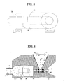
- FIG. 4 shows an exemplary construction of a milling and classifying apparatus.
- toner A of coarse particles to be milled is fed to injection nozzle 42 from the raw material inlet 43 disposed at upper side of the collision mill 41.
- the toner of coarse particles flows with stream B at high velocity, and collides against opposing collision plate 35 thereby is divided into fine particles.
- the toner of fine particles C divided by the collision with the collision plate, flows between collision plate support 36 of column or cylinder shape and the inner wall of milling room 44, and on the way collide with flame-like collision member 38 of which the face is perpendicular to the support axis, and is further divided, then flow into outlet 47.
- the face of collision member 38 is not necessarily required to be perpendicular to the support axis; for example, the face of collision member 38 may be somewhat inclined within about 10 degrees from the direction perpendicular to the support axis.
- the air classifier according to the present invention comprises a dispersion room into which a mixture of primary air and the powder is introduced, and a classification room which is equipped with a center core at the upper side, a separator core at the lower side, and a secondary air inlet at the side wall, wherein the classification room is disposed below the dispersion room, and the mixture of the primary air and the powder flows from the dispersion room into the classification room, and a flow stabilizer is arranged at a central suction of the separator core to control swirl stream generated within the classification room so as to centrifuge the powder into coarse particles and fine particles by action of the swirl stream.
- the flow stabilizer is disposed within 500 mm from the center of the central suction of the separator core, thereby appropriate control of swirl flow may be obtained without disturbing the swirl flow, thus resulting in higher classification accuracy.
- the site of the flow stabilizer is over 500 mm from the inner wall, the swirl flow may be adversely disturbed significantly.
- the flow stabilizer is equipped with plural blades on a ring pedestal for controlling the air stream and a core-adjusting ring inside the pedestal for controlling the suction pressure at the central suction of the separator core.
- a core-adjusting ring inside the pedestal for controlling the suction pressure at the central suction of the separator core.
- the core-adjusting ring for adjusting the suction pressure allows shortening the operating period.
- the space between the blades in the flow stabilizer is 0.1 mm to 50 mm, thereby the classification accuracy may be enhanced still more.
- the space is more than 50 mm, the swirl velocity is lower at the central area of the swirl stream, possibly resulting in insufficient classification.
- each blade in the flow stabilizer is folded in a perpendicular direction at a site more distant than the middle of the blade, thereby the classification accuracy may be enhanced still more.
- the swirl stream turns excessively toward the central portion, possibly resulting in insufficient classification.
- the angle between the folded surface and unfolded surface of the folded blades in the flow stabilizer is from 90 degrees to 180 degrees, thereby the classification accuracy may be enhanced still more.
- the angle between the folded surface and unfolded surface is above 180 degrees, the blade tends to resist against the air stream, possibly resulting in significant disturbance of swirl stream.
- the collision member is formed of a ceramic material, thereby the abrasion resistance of the collision member may be remarkably enhanced.
- the surface roughness Rmax of the collision member is processed as smooth as 1.6 ⁇ m or less, thereby the toner deposition may be reduced even in a continuous operation, resulting in improved maintenance such as shortened period for cleaning the deposited toner.
- the collision member may be polished into a mirror surface by buff polishing, for example.
- the angle and the space of the attached blades in the flow stabilizer are adjustable by a bolt mechanism, and the height and the thickness of the blades are adjustable by exchanging detachably the blades, thereby the flow stabilizer may be optimized corresponding to the desired particle size distribution.
- the inner diameter of the suction of the flow stabilizer is adjustable by exchanging detachably the core-adjusting ring, thereby the inner diameter of the suction may be optimized corresponding to the desired particle size distribution.
- the flow stabilizer is detachably attached by a mating mechanism, thereby the maintenance may be improved such that the period for cleaning the deposited toner is shortened.
- FIG. 2 shows an exemplary air classifier in the prior art.
- reference numbers 21 to 31 indicate as follows, 21: air duct, 22: powder feed pipe, 23: casing, 24: classification room, 25: secondary air inlet, 26: separator core, 27: central suction, 28: center core, 29: clamp, 30: fine particle outlet, and 31: coarse particle outlet.
- One of the futures according to the present invention is that a flow stabilizer is provided at central suction 27 in order to control the circular flow within the classification room.
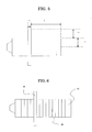
- FIG. 7 is a schematic cross section of an exemplary flow stabilizer utilized in the present invention. As shown in FIG. 7, the flow stabilizer is equipped with plural blades 53 on ring pedestal 52 for controlling gas stream. Pedestal 52 is engaged with central suction 27 (FIG. 2) of the separator core by means of a screw mechanism.
- central suction 27 FIG. 2
- the reference numbers indicate as follows, 73: blade width, 74: blade space, 75: blade thickness, 76: inner diameter of pedestal, and 77: angle of attached blade.
- Pedestal 52 is fitted into central suction 27 (FIG. 2) of the separator core, thus the inner diameter of central suction 27 is reduced into the inner diameter of pedestal 52.
- a core-adjusting ring for controlling suction pressure may be detachably attached to the inside of pedestal 52 by means of bolts, which allows to alter the substantial diameter of central suction 27; namely, attachment and detachment of the core-adjusting ring may bring about decrease and increase of the inner diameter or core diameter 76 of the central suction, which also allows to control the suction pressure.
- FIG. 8 is a schematic vertical section of an exemplary flow stabilizer utilized in the present invention, in which 52 indicates the pedestal, 53 indicates the blade, and 82 indicates the height of the flow stabilizer.
- FIG. 9 is a schematic cross section of an exemplary air classifier according to the present invention, in which flow stabilizer 50 is mounted to central suction 27 of separator core 26.
- the other reference numbers indicate as follows, 21: air duct, 22: powder feed pipe, 23: casing, 24: classification room, 25: secondary air inlet, 28: center core, 30: fine particle outlet, and 31: coarse particle outlet.
- FIG. 10 is a schematic cross section of separator core 59 and flow stabilizer 50 disposed at central suction 27 (FIG. 9).
- the reference numbers indicate as follows, 52: pedestal, 53: blade, 54: core-adjusting ring, and 55: core.
- the inner diameter of the core can be reduced through attachment of core-adjusting ring 24.
- FIG. 11 shows a blade which is folded into angle 97 at distance 96 from the edge.
- Various blades may be prepared with various folded angles and exchanged depending on requirements.
- Air duct 21 is provided at the top of casing 23, and powder feed pipe 22 is provided at the upper side wall of casing 23 for feeding the mixture of primary air and the powder.
- Coarse particle outlet 31 is provided at the bottom of the lower casing which also serves as a hopper of accumulated powder.
- the lower casing is detachably attached to the upper casing by means of a clamp mechanism (not shown).
- Conical separator core 26 is disposed concentrically with center core 28 at above the coarse particle outlet 31 and beneath the center core 28, and classification room 24 is provided at the space between separator core 26 and center core 28.
- Fine particle outlet 30 is disposed below the center of separator core 26.
- Flow stabilizer 50 is mounted to central suction 27 of conical separator core 26.
- Blades 53 of flow stabilizer 50 are separable from pedestal 52, and the blade angle 97, blade space 74, blade width 73, blade thickness 75, blade height 82, and inner diameter of core 76, and the like may be designed wide-variously, which allows to classify toners with significantly high accuracy by selecting an optimum condition.
- the method for producing a toner according to the present invention produces a toner using one of milling and classifying apparatuses, collision mills, and air classifiers according to the present invention.
- the toners according to the present invention may be produced by the method for producing a toner according to the present invention.
- the raw materials for the toner may be properly selected depending on the application; examples of the raw materials include binder resins, colorants, releasing agents, charge control agents, inorganic fine powders, and the like.
- the binder resin may be properly selected from conventional ones such as vinyl resins, polyester resins, polyol resins, and the like depending on the application.
- vinyl resins include styrene mono-polymers such as polystyrenes, poly-p-chlorostyrenes, polyvinyltoluenes, and other polymers of styrene and substituted styrenes; styrene copolymers such as styrene-p-chlorostyrene copolymers, styrene-propylene copolymers, styrene-vinyltoluene copolymers, styrene-vinylnaphthalene copolymers, styrene-methyl acrylate copolymers, styrene-ethyl acrylate copolymers, styrene-butyl acrylate copolymers, styrene-octyl acrylate copolymers, styrene-methyl methacrylate copolymers, styrene-eth
- polyester resins for binder resins described above may be synthesized from divalent alcohols, dibasic acids, alcohols and carboxylic acids having three or more functionalities, and the like shown below.
- divalent alcohols examples include ethylene glycol, triethylene glycol, 1,2-propylene glycol, 1,3-propylene glycol, 1,4-butanediol, neopentyl glycol, 1,4-butenediol, 1,4-bis(hydroxylmethyl)cyclohexane, bisphenol A, hydrogenated bisphenol A, polyoxyethylene bisphenol A, polyoxypropylene(2,2)-2,2'-bis(4-hydroxyphenyl)propane, polyoxypropylene(3,3)-2,2-bis(4-hydroxyphenyl)propane, polyoxyethylene(2,0)-2,2-bis(4-hydroxyphenyl)propane, and polyoxypropylene(2,0)-2,2'-bis(4-hydroxyphenyl)propane.
- dibasic acids examples include maleic acid, fumaric acid, mesaconic acid, citraconic acid, itaconic acid, glutaconic acid, phthalic acid, isophthalic acid, terephthalic acid, cyclohexane-dicarboxylic acid, succinic acid, adipic acid, sebacic acid, malonic acid, linolenic acid; anhydrides of the above acids; and esters of the above acids and lower alcohols.
- alcohols and carboxylic acids having three or more functionalities include glycerin, trimethylolpropane, and pentaerythritol; and polycarboxylic acids having three or more carboxyl groups such as trimellitic acid and pyromellitic acid.
- the polyol resins described above may be prepared by allowing the following components to react epoxy resins, with alkylene oxide adduct of dihydric phenol or glycidyl ether of the alkylene oxide adduct, compounds having in the molecule thereof one active hydrogen atom which is capable of reacting with epoxy group, and compounds having in the molecule thereof two or more active hydrogen atoms which are capable of reacting with epoxy group.
- the binder resin described above may contain another resin depending on requirements in order to improve processing ability, for example.
- the additional resin may be selected from epoxy resins, polyamide resins, urethane resins, phenol resins, butyral resins, rosin resins, modified-rosin resins, and terpene resins.
- Specific examples of the epoxy resins may be polycondensate of bisphenols such as bisphenol A, bisphenol F, and epichlorohydrin.
- the colorants may be properly selected depending on the application, examples thereof include black, yellow, orange, red, violet, blue, and green pigments, and the like.
- black pigments examples include carbon blacks such as oil furnace black, channel black, lamp black, and acetylene black; azine dyes such as aniline black, azo dyes of metal salts, metal oxides, complex metal oxides, and the like.
- yellow pigment examples include Cadmium Yellow, Mineral Fast Yellow, Nickel Titan Yellow, Naples Yellow, Naphthol Yellow S, Hansa Yellow G, Hansa Yellow 10G, Benzidine Yellow GR, Quinoline Yellow Lake, Permanent Yellow NCG, and Tartrazine Lake.
- orange pigment examples include Molybdate Orange, Permanent Orange GTR, Pyrazolone Orange, Vulcan Orange, Indanthrene Brilliant Orange RK, Benzidine Orange G, and Indanthrene Brilliant Orange GK.
- red pigment examples include red iron oxide, Cadmium Red, Permanent Red 4R, Lithol Red, Pyrazolone Red, Watchung Red Calcium Salt, Lake Red D, Brilliant Carmine 6B, Eosine Lake, Rhodamine Lake B, Alizarine Lake, and Brilliant Carmine 3B.
- purple pigment examples include Fast Violet B and Methyl Violet Lake.
- blue pigment examples include Cobalt Blue, Alkali Blue, Victoria Blue Lake, Phthalocyanine Blue, metal-free Phthalocyanine Blue, partially chlorinated Phthalocyanino Blue, Fast Sky Blue, and Indanthrene Blue BC.
- green pigment examples include Chrome Green, chromium oxide, Pigment Green B, and Malachite Green Lake.
- These pigments may be used alone or in combination.
- the amount of the colorants may be properly selected depending on the application; preferably, the amount of the pigment is 0.1 to 50 parts by mass based on 100 parts by mass of the binder resin.
- Examples of the releasing agent include synthetic waxes such as polyethylene with a lower molecular weight, polypropylene with a lower molecular weight, and copolymers thereof; vegetable waves such as candelilla wax, carnauba wax, rice wax, wood wax, and jojoba wax; animal wax such as beeswax, lanolin, and whale oil; mineral wax such as montan wax and ozokerite; wax of fats and oils such as hydrogenated castor oil, hydroxy stearic acid, fatty amide, and phenol fatty ester.
- synthetic waxes such as polyethylene with a lower molecular weight, polypropylene with a lower molecular weight, and copolymers thereof
- vegetable waves such as candelilla wax, carnauba wax, rice wax, wood wax, and jojoba wax
- animal wax such as beeswax, lanolin, and whale oil
- mineral wax such as montan wax and ozokerite
- wax of fats and oils such as hydrogenated
- the charge control agent for control the toner into positive charge, may be nigrosine or quaternary ammonium salt thereof, metal complexes or salts of imidazole, or the like.
- the charge control agent, for control the toner into negative charge may be metal complexes or salts of salicylic acid, organic boron salts, calix arene compounds, or the like.
- an inorganic fine powder is added to the toner utilized in the present invention in order to enhance the fluidity of the toner.
- a specific additional inorganic powder is often effective to provide a toner with superior fluidity and higher durability, especially with regard to the toner adapted to the present invention that has a relatively small particle size and contains a releasing agent.
- Examples of the inorganic powder serving to enhance the fluidity of the toner are oxides and composite oxides comprising Si, Ti, Al, Mg, Ca, Sr, Ba, In, Ga, Ni, Mn, W, Fe, Co, Zn, Cr, Mo, Cu, Ag, V, and Zr.
- oxides and composite oxides comprising Si, Ti, Al, Mg, Ca, Sr, Ba, In, Ga, Ni, Mn, W, Fe, Co, Zn, Cr, Mo, Cu, Ag, V, and Zr.
- fine powders of silicon dioxide or silica, titanium dioxide or titania, and aluminum oxide or alumina are particularly preferable for the present invention.
- the inorganic powder described above is surface-treated to make them hydrophobic.
- surface treatment agents for making the inorganic powders include dimethyldichlorosilane, trimethylchlorosilane, methyltrichlorosilane, allyldimethyldichlorosilane, allylphenyldichlorosilane, benzyldimethylchlorosilane, bromomethyldimethylchlorosilane, alpha -chloroethyltrichlorosilane, p-chloroethyltrichlorosilane, chloromethyldimethylchlorosilane, chloromethyltrichlorosilane, p-chlorophenyltrichlorosilane, 3-chloropropyltrichlorosilane, 3-chloropropyltrimethoxysilane, vinyltriethoxysilane, vinylmethoxysilane, vinyltris(beta-me).
- the content of the inorganic fine powder is of 0.1 % by mass to 2 % by mass based of the entire mass of the toner.
- the content is less than 0.1 % by mass, aggregation of toner particles may not be effectively prevented, and when the content is more than 2 % by mass, the toner particles tend to scatter between thin line images, the inside of the image forming apparatus tends to be stained with the toner particles, and photoconductors are often scratched or abraded with the inorganic powder.
- additives described later may be incorporated into the toner depending on the application, for example, fluidizing agents such as colloidal silica, abrasive materials such as titanium oxide, aluminum oxide, and silicon carbide, and lubricant such as metal salts of fatty acids.
- the other additive may be lubricant powders such as polytetrafluoroethylene fluorine-resin powder, zinc stearate powder, and polyvinylidene fluoride, abrasive materials such as cerium oxide powder and strontium titanate, and conductivity-imparting materials such as carbon black, zinc oxide powder, and tin oxide powder. Furthermore, white or black fine particles having a traverse polarity may be added in a small amount to improve developing property.
- lubricant powders such as polytetrafluoroethylene fluorine-resin powder, zinc stearate powder, and polyvinylidene fluoride
- abrasive materials such as cerium oxide powder and strontium titanate
- conductivity-imparting materials such as carbon black, zinc oxide powder, and tin oxide powder.
- white or black fine particles having a traverse polarity may be added in a small amount to improve developing property.
- the mixer may be selected from double-cone mixers, V-type mixers, drum mixers, super mixers, Henschel mixers, and Nauter mixers, then the mixture is kneaded.
- the kneading of the mixture may be carried out in a discontinuous manner by use of pressure kneaders, Banbury mixers, or twin rolls, for example.
- the kneading is carried out in a continuous manner from the viewpoint of productivity by use of a single-screw or double screw extruder.
- extruder examples include Model KTK double screw extruder (by Kobe Steel, Ltd.), Model TEM double screw extruder (by Toshiba Machine Co., Ltd.), extruders (by KCK Co., Ltd.), Model PCM double screw extruder (by Ikegai Tekko Co., Ltd.), Model KEX double screw extruder (by Kurimoto, Ltd.), and continuous kneaders (by Buss Co., Ltd.).
- the barrel of extruders utilized for the kneading is divided into plural parts, and a heating unit such as an electric heater and a cooling unit such as a cooling pipe are provided to the barrel, thereby the temperature is controlled by use of a thermal controller.
- a heating unit such as an electric heater
- a cooling unit such as a cooling pipe
- Two screws are engaged within the barrel, and are rotated in a same direction at a velocity of 100 to 500 rpm.
- the construction of the screws may be properly selected depending on the application; for example, feeding portion and kneading portion are constructed into the screws.
- the screw feeder feeds the mixture of the toner raw materials from the hopper into the region of feeding screw.
- the mixture is gradually heated at the region of feeding screw, then the mixture raises its temperature by internal heat built-up due to high shear stress derived by the kneading screw, which promotes the dispersion of toner raw materials, thus the mixture turns into a molten state from a solid or semi-molten state.
- An optional secondary kneading screw at the rear region and/or other designs of screws may bring about higher temperature, which may melt the mixture sufficiently and enhance the wetting ability between the resin and the colorant.
- plural vents for degassing the mixture are provided behind the site where the mixture melts, more preferably, the plural vents are partly or entirely vacuumed by means of a vacuum pump and the like, thereby the mixture modifies the filled condition, the dispersing ability is enhanced, and the volatiles are efficiently removed.
- Single screws or double screws are typically suited to continuous extruders.
- the number of screw grooves may be designed from double groove, triple groove, and the like, considering the dispersing ability, productivity, kneading temperature, and the like.
- the size of the extruder is selected such that the feeding region, kneading region, and plural vents are appropriately arranged.
- L/D is 20 or more, and more preferably is 25 or more, wherein the inner diameter of barrel is D millimeter (mm) and the distance between the inlet of the raw materials and the outlet of the mixture is L (mm).
- the mixed product is calendered by means of a calender roll and the like, and cooled by use of air, water, and the like. Then, the mixed product is gradually divided into a desired particle size such that firstly the mixed product is subjected to granulation by means of a crusher, hammer mill, feather mill, or the like, thereafter is subjected to milling by means of a milling and classifying apparatus based on collision such as a jet mill and jet atomizer. After the milling, the mixed product is subjected to classification by means of an inertia-classification elbow jet, centrifugal-classification Micro Plex, DS separator, or the like, thereby a milled-classified toner may be obtained.
- the toner When the toner includes external additives, specific amounts of additives are generally compounded to the milled-classified toner, and stirred and mixed by means of a high-share mixer such as a Henschel mixer, super mixer, or the like. Then, the mixture is subjected to screening for removing contaminants and course particles, thereby the final toner product is obtained.
- a high-share mixer such as a Henschel mixer, super mixer, or the like.
- FIG. 4 shows an exemplary construction of a milling and classifying apparatus.
- toner A of coarse particles to be milled was fed to injection nozzle 42 from the raw material inlet disposed at upper side of the collision mill 41.
- high-velocity stream B ejected from nozzle 42 the toner of coarse particles flowed with stream B at a high velocity, and collided against an opposing collision plate 45 thereby was divided into fine particles.
- the divided particles flowed between collision-plate support 36 and the inner wall of milling room 44 and collided against collision member 38 on the way, then flowed into outlet 47.
- the collision plate, collision-plate support, and collision member are shown in FIG. 6. As shown in FIG. 6, the collision plate was constructed from plural parts.
- the toner was prepared by mixing 20 parts of a styrene-acrylic resin, 80 parts of a polyester resin, 10 parts of carbon black, 4.95 parts of carnauba wax, and 2 parts of a quaternary ammonium salt by means of a super mill, then the resulting mixture was melted and kneaded by means of Model TEM double screw extruder (by Toshiba Machine Co., Ltd.). After cooling the melted and kneaded mixture to ambient temperature, the mixture was crushed by means of a hammer mill to prepare a toner of coarse particles.
- the toner of coarse particles was milled and classified by means of the milling and classifying apparatus shown in FIG. 12, which is constructed from air classifier 91 and collision mill.
- Various evaluations were conducted with respect to the toner and the apparatus as follows. The results are shown in Table 2.
- Toners were produced and the evaluations were conducted in the same manner as Example 1-1, except that the milling and classifying apparatus was constructed under the specifications shown in Table 1. The results are shown in Table 1.
- a toner was produced and the evaluations were conducted in the same manner as Example 1-1, except that the milling and classifying apparatus was constructed without the collision member downstream of the collision plate. The results are shown in Table 1 summarily.
- Table 1 demonstrate that the milling and classifying apparatus according to the present invention can produce toners with narrower particle size distributions without reducing the output rate, namely, without deteriorating the productivity.
- a collision mill was constructed as shown in FIG. 4 in the same manner as Example 1-1, except for the specifications shown in Table 2.
- experimental factors were radius of the collision plate R (mm), distance between the collision plate and the collision member L (mm), height of the collision member from the support, thickness of the collision member, surface roughness of the collision member, and material of the collision member.
- the toner utilized in Example 2-1 to 2-9 was substantially the same as that of Example 1-1.
- Example 2 A toner was produced and the evaluations were conducted in the same manner as Example 2-1, except that the milling and classifying apparatus was constructed without the collision member downstream of the collision plate. The results are shown in Table 2 summarily.
- An air classifier was constructed as shown in FIG. 9 in the same manner as Example 1-1, except for the specifications shown in Table 3.
- experimental factors were blade angle, blade space, blade height, blade thickness, blade width, and folded angle of blade in the flow stabilizer.
- the toner utilized in Example 3-1 to 3-12 was substantially the same as that of Example 1-1.
- a toner was produced and the evaluations were conducted in the same manner as Example 3-1, except that the air classifier was constructed without the flow stabilizer at the central suction. The results are shown in Table 3 summarily.
- Example 3-1 was mounted detachably to the apparatus, which demonstrated that the period for cleaning the air classifier was shortened by 20 %.
Landscapes
- Physics & Mathematics (AREA)
- General Physics & Mathematics (AREA)
- Engineering & Computer Science (AREA)
- Food Science & Technology (AREA)
- Developing Agents For Electrophotography (AREA)
- Combined Means For Separation Of Solids (AREA)
Applications Claiming Priority (2)
| Application Number | Priority Date | Filing Date | Title |
|---|---|---|---|
| JP2004205500 | 2004-07-13 | ||
| JP2004211214 | 2004-07-20 |
Publications (3)
| Publication Number | Publication Date |
|---|---|
| EP1616624A2 true EP1616624A2 (de) | 2006-01-18 |
| EP1616624A3 EP1616624A3 (de) | 2006-03-15 |
| EP1616624B1 EP1616624B1 (de) | 2009-12-16 |
Family
ID=34937835
Family Applications (1)
| Application Number | Title | Priority Date | Filing Date |
|---|---|---|---|
| EP20050015126 Ceased EP1616624B1 (de) | 2004-07-13 | 2005-07-12 | Vorrichtung zur Zerkleinerung und Klassifikation, Pneumatische Prallmühle, Sichter und Verfahren zur Herstellung von Tonern |
Country Status (2)
| Country | Link |
|---|---|
| EP (1) | EP1616624B1 (de) |
| DE (1) | DE602005018292D1 (de) |
Cited By (8)
| Publication number | Priority date | Publication date | Assignee | Title |
|---|---|---|---|---|
| CN102397841A (zh) * | 2011-11-28 | 2012-04-04 | 河南省康星药业有限公司 | 双向气流超微粉筛选机 |
| CN113019641A (zh) * | 2021-03-30 | 2021-06-25 | 重庆医药高等专科学校 | 一种制药原材料气流粉碎装置 |
| CN114939531A (zh) * | 2022-05-05 | 2022-08-26 | 中国计量大学 | 一种基于惯性冲击原理的微纳颗粒分径仪 |
| CN115999728A (zh) * | 2023-02-22 | 2023-04-25 | 江苏天诚锌业科技有限公司 | 一种具有给料结构的锌粉加工设备 |
| CN116747976A (zh) * | 2023-06-16 | 2023-09-15 | 湖南经源科技有限公司 | 一种锂电材料制备用流化床气流粉碎分级机 |
| CN117816326A (zh) * | 2024-03-05 | 2024-04-05 | 临沂昊泉硅业科技有限公司 | 一种复合气凝胶粉体材料制备用气流粉碎装置 |
| CN118634934A (zh) * | 2024-07-01 | 2024-09-13 | 弘力科技(北京)有限公司 | 一种整粒组件、颗粒分布窄精细整粒粉碎设备和粉碎方法 |
| WO2025071529A1 (en) * | 2023-09-27 | 2025-04-03 | Benli Vehbi Cem | Paint and ink grinding machine |
Family Cites Families (6)
| Publication number | Priority date | Publication date | Assignee | Title |
|---|---|---|---|---|
| KR950006885B1 (ko) * | 1991-07-16 | 1995-06-26 | 캐논 가부시기가이샤 | 충돌식 기류분쇄기, 미분체제조장치 및 토너의 제조방법 |
| JPH06154709A (ja) * | 1992-11-19 | 1994-06-03 | Mita Ind Co Ltd | 粉粒体分級機 |
| KR960018777A (ko) * | 1994-11-29 | 1996-06-17 | 미타 요시히로 | 전자사진용토너 및 현상제 |
| US6103440A (en) * | 1998-05-04 | 2000-08-15 | Xerox Corporation | Toner composition and processes thereof |
| FR2795190B1 (fr) * | 1999-06-17 | 2002-03-15 | Ricoh Kk | Developpateur, recipient de developpateur, et procede et appareil de formation d'images |
| JP2004073918A (ja) * | 2002-08-12 | 2004-03-11 | Kao Corp | トナーの製造方法 |
-
2005
- 2005-07-12 EP EP20050015126 patent/EP1616624B1/de not_active Ceased
- 2005-07-12 DE DE200560018292 patent/DE602005018292D1/de not_active Expired - Lifetime
Cited By (12)
| Publication number | Priority date | Publication date | Assignee | Title |
|---|---|---|---|---|
| CN102397841A (zh) * | 2011-11-28 | 2012-04-04 | 河南省康星药业有限公司 | 双向气流超微粉筛选机 |
| CN102397841B (zh) * | 2011-11-28 | 2013-08-21 | 河南省康星药业股份有限公司 | 双向气流超微粉筛选机 |
| CN113019641A (zh) * | 2021-03-30 | 2021-06-25 | 重庆医药高等专科学校 | 一种制药原材料气流粉碎装置 |
| CN113019641B (zh) * | 2021-03-30 | 2022-05-27 | 重庆医药高等专科学校 | 一种制药原材料气流粉碎装置 |
| CN114939531A (zh) * | 2022-05-05 | 2022-08-26 | 中国计量大学 | 一种基于惯性冲击原理的微纳颗粒分径仪 |
| CN115999728A (zh) * | 2023-02-22 | 2023-04-25 | 江苏天诚锌业科技有限公司 | 一种具有给料结构的锌粉加工设备 |
| CN115999728B (zh) * | 2023-02-22 | 2023-10-13 | 江苏天诚锌业科技有限公司 | 一种具有给料结构的锌粉加工设备 |
| CN116747976A (zh) * | 2023-06-16 | 2023-09-15 | 湖南经源科技有限公司 | 一种锂电材料制备用流化床气流粉碎分级机 |
| WO2025071529A1 (en) * | 2023-09-27 | 2025-04-03 | Benli Vehbi Cem | Paint and ink grinding machine |
| CN117816326A (zh) * | 2024-03-05 | 2024-04-05 | 临沂昊泉硅业科技有限公司 | 一种复合气凝胶粉体材料制备用气流粉碎装置 |
| CN117816326B (zh) * | 2024-03-05 | 2025-10-14 | 临沂昊泉硅业科技有限公司 | 一种复合气凝胶粉体材料制备用气流粉碎装置 |
| CN118634934A (zh) * | 2024-07-01 | 2024-09-13 | 弘力科技(北京)有限公司 | 一种整粒组件、颗粒分布窄精细整粒粉碎设备和粉碎方法 |
Also Published As
| Publication number | Publication date |
|---|---|
| EP1616624B1 (de) | 2009-12-16 |
| EP1616624A3 (de) | 2006-03-15 |
| DE602005018292D1 (de) | 2010-01-28 |
Similar Documents
| Publication | Publication Date | Title |
|---|---|---|
| US7438245B2 (en) | Milling and classifying apparatus, collision mill, air classifier, toner, and method for producing toner | |
| KR101548090B1 (ko) | 분체 입자용 열 처리 장치 및 토너의 제조 방법 | |
| US7506830B2 (en) | Apparatus for modifying surfaces of toner particles | |
| EP1616624B1 (de) | Vorrichtung zur Zerkleinerung und Klassifikation, Pneumatische Prallmühle, Sichter und Verfahren zur Herstellung von Tonern | |
| JP4290107B2 (ja) | トナーの製造方法 | |
| JP4944401B2 (ja) | 衝突気流式粉砕機 | |
| JP3943793B2 (ja) | トナーの製造方法 | |
| JP5366524B2 (ja) | トナーの熱処理装置及びトナーの製造方法 | |
| JP4448019B2 (ja) | トナーの製造方法およびトナー粒子の表面を改質するための装置 | |
| JP3486524B2 (ja) | トナーの製造方法及び製造システム | |
| US7866581B2 (en) | Method of manufacturing toner | |
| JP6516420B2 (ja) | 粉体粒子の熱処理装置及び粉体粒子の製造方法 | |
| JP2002189315A (ja) | トナーの製造方法 | |
| JP2004078063A (ja) | トナー粒子の分級方法及び製造方法 | |
| JP6533431B2 (ja) | 粉体粒子の熱処理装置及びトナーの製造方法 | |
| JP2006159075A (ja) | 衝突気流式粉砕装置、静電荷像現像用トナーの製造方法および静電荷像現像用トナー | |
| JP4869168B2 (ja) | トナーの表面改質装置 | |
| JPH1115194A (ja) | トナーの製造方法 | |
| JPH0792735A (ja) | トナーの製造方法及びその製造装置 | |
| JP5282517B2 (ja) | 静電荷像現像用トナーの製造方法及び静電荷像現像用トナー | |
| JP6957303B2 (ja) | 熱処理装置及び粉体粒子の製造方法 | |
| JP3220918B2 (ja) | トナーの製造方法及びその製造装置 | |
| JP3138379B2 (ja) | 静電荷像現像用トナーの製造方法 | |
| JP3382468B2 (ja) | トナーの製造方法 | |
| JPH07109523B2 (ja) | 静電荷像現像用トナーの製造方法 |
Legal Events
| Date | Code | Title | Description |
|---|---|---|---|
| PUAI | Public reference made under article 153(3) epc to a published international application that has entered the european phase |
Free format text: ORIGINAL CODE: 0009012 |
|
| AK | Designated contracting states |
Kind code of ref document: A2 Designated state(s): AT BE BG CH CY CZ DE DK EE ES FI FR GB GR HU IE IS IT LI LT LU LV MC NL PL PT RO SE SI SK TR |
|
| AX | Request for extension of the european patent |
Extension state: AL BA HR MK YU |
|
| PUAL | Search report despatched |
Free format text: ORIGINAL CODE: 0009013 |
|
| AK | Designated contracting states |
Kind code of ref document: A3 Designated state(s): AT BE BG CH CY CZ DE DK EE ES FI FR GB GR HU IE IS IT LI LT LU LV MC NL PL PT RO SE SI SK TR |
|
| AX | Request for extension of the european patent |
Extension state: AL BA HR MK YU |
|
| 17P | Request for examination filed |
Effective date: 20060906 |
|
| AKX | Designation fees paid |
Designated state(s): DE FR GB |
|
| 17Q | First examination report despatched |
Effective date: 20061116 |
|
| GRAP | Despatch of communication of intention to grant a patent |
Free format text: ORIGINAL CODE: EPIDOSNIGR1 |
|
| GRAS | Grant fee paid |
Free format text: ORIGINAL CODE: EPIDOSNIGR3 |
|
| GRAA | (expected) grant |
Free format text: ORIGINAL CODE: 0009210 |
|
| AK | Designated contracting states |
Kind code of ref document: B1 Designated state(s): DE FR GB |
|
| REG | Reference to a national code |
Ref country code: GB Ref legal event code: FG4D |
|
| REF | Corresponds to: |
Ref document number: 602005018292 Country of ref document: DE Date of ref document: 20100128 Kind code of ref document: P |
|
| PLBE | No opposition filed within time limit |
Free format text: ORIGINAL CODE: 0009261 |
|
| STAA | Information on the status of an ep patent application or granted ep patent |
Free format text: STATUS: NO OPPOSITION FILED WITHIN TIME LIMIT |
|
| 26N | No opposition filed |
Effective date: 20100917 |
|
| REG | Reference to a national code |
Ref country code: DE Ref legal event code: R082 Ref document number: 602005018292 Country of ref document: DE Representative=s name: MEISSNER BOLTE PATENTANWAELTE RECHTSANWAELTE P, DE Ref country code: DE Ref legal event code: R082 Ref document number: 602005018292 Country of ref document: DE Representative=s name: MEISSNER, BOLTE & PARTNER GBR, DE |
|
| REG | Reference to a national code |
Ref country code: DE Ref legal event code: R082 Ref document number: 602005018292 Country of ref document: DE Representative=s name: MEISSNER, BOLTE & PARTNER GBR, DE |
|
| REG | Reference to a national code |
Ref country code: FR Ref legal event code: PLFP Year of fee payment: 12 |
|
| REG | Reference to a national code |
Ref country code: FR Ref legal event code: PLFP Year of fee payment: 13 |
|
| REG | Reference to a national code |
Ref country code: FR Ref legal event code: PLFP Year of fee payment: 14 |
|
| PGFP | Annual fee paid to national office [announced via postgrant information from national office to epo] |
Ref country code: DE Payment date: 20180723 Year of fee payment: 14 Ref country code: FR Payment date: 20180725 Year of fee payment: 14 |
|
| PGFP | Annual fee paid to national office [announced via postgrant information from national office to epo] |
Ref country code: GB Payment date: 20180719 Year of fee payment: 14 |
|
| REG | Reference to a national code |
Ref country code: DE Ref legal event code: R119 Ref document number: 602005018292 Country of ref document: DE |
|
| GBPC | Gb: european patent ceased through non-payment of renewal fee |
Effective date: 20190712 |
|
| PG25 | Lapsed in a contracting state [announced via postgrant information from national office to epo] |
Ref country code: DE Free format text: LAPSE BECAUSE OF NON-PAYMENT OF DUE FEES Effective date: 20200201 Ref country code: GB Free format text: LAPSE BECAUSE OF NON-PAYMENT OF DUE FEES Effective date: 20190712 |
|
| PG25 | Lapsed in a contracting state [announced via postgrant information from national office to epo] |
Ref country code: FR Free format text: LAPSE BECAUSE OF NON-PAYMENT OF DUE FEES Effective date: 20190731 |