EP1614758A2 - Vorrichtung zur Durchführung von Messungen und/oder Probenahmen in Metallschmelzen - Google Patents
Vorrichtung zur Durchführung von Messungen und/oder Probenahmen in Metallschmelzen Download PDFInfo
- Publication number
- EP1614758A2 EP1614758A2 EP05012272A EP05012272A EP1614758A2 EP 1614758 A2 EP1614758 A2 EP 1614758A2 EP 05012272 A EP05012272 A EP 05012272A EP 05012272 A EP05012272 A EP 05012272A EP 1614758 A2 EP1614758 A2 EP 1614758A2
- Authority
- EP
- European Patent Office
- Prior art keywords
- lance holder
- lance
- sublance
- parts
- sublanzenkörper
- Prior art date
- Legal status (The legal status is an assumption and is not a legal conclusion. Google has not performed a legal analysis and makes no representation as to the accuracy of the status listed.)
- Granted
Links
Images

Classifications
-
- C—CHEMISTRY; METALLURGY
- C21—METALLURGY OF IRON
- C21B—MANUFACTURE OF IRON OR STEEL
- C21B7/00—Blast furnaces
- C21B7/24—Test rods or other checking devices
-
- F—MECHANICAL ENGINEERING; LIGHTING; HEATING; WEAPONS; BLASTING
- F27—FURNACES; KILNS; OVENS; RETORTS
- F27B—FURNACES, KILNS, OVENS OR RETORTS IN GENERAL; OPEN SINTERING OR LIKE APPARATUS
- F27B3/00—Hearth-type furnaces, e.g. of reverberatory type; Electric arc furnaces ; Tank furnaces
- F27B3/10—Details, accessories or equipment, e.g. dust-collectors, specially adapted for hearth-type furnaces
- F27B3/28—Arrangement of controlling, monitoring, alarm or the like devices
-
- C—CHEMISTRY; METALLURGY
- C21—METALLURGY OF IRON
- C21C—PROCESSING OF PIG-IRON, e.g. REFINING, MANUFACTURE OF WROUGHT-IRON OR STEEL; TREATMENT IN MOLTEN STATE OF FERROUS ALLOYS
- C21C5/00—Manufacture of carbon-steel, e.g. plain mild steel, medium carbon steel or cast steel or stainless steel
- C21C5/28—Manufacture of steel in the converter
- C21C5/42—Constructional features of converters
- C21C5/46—Details or accessories
- C21C5/4673—Measuring and sampling devices
-
- F—MECHANICAL ENGINEERING; LIGHTING; HEATING; WEAPONS; BLASTING
- F27—FURNACES; KILNS; OVENS; RETORTS
- F27D—DETAILS OR ACCESSORIES OF FURNACES, KILNS, OVENS OR RETORTS, IN SO FAR AS THEY ARE OF KINDS OCCURRING IN MORE THAN ONE KIND OF FURNACE
- F27D19/00—Arrangements of controlling devices
-
- F—MECHANICAL ENGINEERING; LIGHTING; HEATING; WEAPONS; BLASTING
- F27—FURNACES; KILNS; OVENS; RETORTS
- F27D—DETAILS OR ACCESSORIES OF FURNACES, KILNS, OVENS OR RETORTS, IN SO FAR AS THEY ARE OF KINDS OCCURRING IN MORE THAN ONE KIND OF FURNACE
- F27D21/00—Arrangement of monitoring devices; Arrangement of safety devices
- F27D21/0014—Devices for monitoring temperature
-
- G—PHYSICS
- G01—MEASURING; TESTING
- G01K—MEASURING TEMPERATURE; MEASURING QUANTITY OF HEAT; THERMALLY-SENSITIVE ELEMENTS NOT OTHERWISE PROVIDED FOR
- G01K13/00—Thermometers specially adapted for specific purposes
- G01K13/12—Thermometers specially adapted for specific purposes combined with sampling devices for measuring temperatures of samples of materials
- G01K13/125—Thermometers specially adapted for specific purposes combined with sampling devices for measuring temperatures of samples of materials for siderurgical purposes
-
- G—PHYSICS
- G01—MEASURING; TESTING
- G01N—INVESTIGATING OR ANALYSING MATERIALS BY DETERMINING THEIR CHEMICAL OR PHYSICAL PROPERTIES
- G01N1/00—Sampling; Preparing specimens for investigation
- G01N1/02—Devices for withdrawing samples
- G01N1/10—Devices for withdrawing samples in the liquid or fluent state
- G01N1/12—Dippers; Dredgers
- G01N1/125—Dippers; Dredgers adapted for sampling molten metals
-
- G—PHYSICS
- G01—MEASURING; TESTING
- G01N—INVESTIGATING OR ANALYSING MATERIALS BY DETERMINING THEIR CHEMICAL OR PHYSICAL PROPERTIES
- G01N33/00—Investigating or analysing materials by specific methods not covered by groups G01N1/00 - G01N31/00
- G01N33/20—Metals
- G01N33/205—Metals in liquid state, e.g. molten metals
-
- C—CHEMISTRY; METALLURGY
- C21—METALLURGY OF IRON
- C21C—PROCESSING OF PIG-IRON, e.g. REFINING, MANUFACTURE OF WROUGHT-IRON OR STEEL; TREATMENT IN MOLTEN STATE OF FERROUS ALLOYS
- C21C5/00—Manufacture of carbon-steel, e.g. plain mild steel, medium carbon steel or cast steel or stainless steel
- C21C5/28—Manufacture of steel in the converter
- C21C5/42—Constructional features of converters
- C21C5/46—Details or accessories
- C21C5/4606—Lances or injectors
-
- F—MECHANICAL ENGINEERING; LIGHTING; HEATING; WEAPONS; BLASTING
- F27—FURNACES; KILNS; OVENS; RETORTS
- F27D—DETAILS OR ACCESSORIES OF FURNACES, KILNS, OVENS OR RETORTS, IN SO FAR AS THEY ARE OF KINDS OCCURRING IN MORE THAN ONE KIND OF FURNACE
- F27D19/00—Arrangements of controlling devices
- F27D2019/0003—Monitoring the temperature or a characteristic of the charge and using it as a controlling value
-
- F—MECHANICAL ENGINEERING; LIGHTING; HEATING; WEAPONS; BLASTING
- F27—FURNACES; KILNS; OVENS; RETORTS
- F27D—DETAILS OR ACCESSORIES OF FURNACES, KILNS, OVENS OR RETORTS, IN SO FAR AS THEY ARE OF KINDS OCCURRING IN MORE THAN ONE KIND OF FURNACE
- F27D19/00—Arrangements of controlling devices
- F27D2019/0006—Monitoring the characteristics (composition, quantities, temperature, pressure) of at least one of the gases of the kiln atmosphere and using it as a controlling value
Definitions
- the invention relates to a device for carrying out measurements and / or sampling in molten metal with a sublance, which has a Sublanzenelasticity, at one end of a lance holder for receiving an immersion probe is arranged.
- Such devices are well known to those skilled in the art. They are used for measuring or sampling in molten metals. Such sampling is automated in part, with a sublance immersed in a melting vessel for measurement, then the submerged probe placed on the sublance, since it is consumed, discarded and a new immersion probe attached to the sublance. To automate this process, the sublance must be exactly positionable via a probe depot. In practice, however, because of the stresses imposed on a sublance during use, these subluces are slightly bent so that the lance holder is no longer precisely placeable over a submerged probe and can not properly accommodate it. The immersion probes plugged onto the sublances do not have exactly the same length.
- the contact part accommodated in the support tube can not always be reached at the same depth for the mating contact in the sublance.
- These splashes of molten metal are often attached to parts of the sublance, which must remain free for contacting, so that a proper attaching the immersion probes is not possible. This can disrupt the entire steelmaking process.
- Sublances are known, for example, from EP 69 433.
- an attempt is made to counteract the deformation of the sublance during operation by rotating the sublance.
- the arrangement and function of sublances is further described in DE 43 06 332 A1.
- Another sublance is known from EP 143 498 A2.
- the sublance shown here has at joints a seal, such as a rubber ring, which prevents the liquid metal can penetrate into the mechanics.
- the invention has for its object to improve the known subluces and in particular to increase the reliability in automatic operation.
- the object is achieved for the initially characterized invention in that a contact piece is arranged on the lance holder for contacting signal lines of the immersion probe, further characterized in that the Sublanzen emotions is movably connected to the lance holder or a part thereof and / or that the lance holder more against each other having movable parts, wherein the contact piece is arranged movable to the sublance, in particular to Sublanzen emotions.
- the sublance is firmly pushed onto the upper part of the lance holder and preferably held immobile.
- the lower part of the lance holder with the contact piece is movable, so that the probe can be brought into contact with the contact piece.
- the lance holder can adapt to the position of the sensor provided, so that sufficient contact is possible even with slightly bent components or when molten metal adheres to the sublime.
- Different insertion depths of the sublance in the support tube of the immersion probe are also compensated in this way.
- the Sublanzen stresses with the lance holder and / or the parts of the lance holder are arranged in the axial direction and / or radially movable.
- the axial mobility and the radial mobility are realized by mutually different pairs of connecting parts in order to obtain the highest possible flexibility and adaptability.
- the mobility is realized by arranged between rigid parts elastic parts, wherein the elastic parts may be formed as a spring, for example as a helical spring or as an elastic ring.
- a part of the lance holder has a receiving bore in which a pin of a second part of the lance holder is arranged to be axially movable, wherein a helical spring is arranged between the first and the second part of the lance holder.
- the helical spring between a arranged on the front side or on the peripheral surface of the pin stop surface and arranged on or in the bore second stop surface is arranged. The mobility-ensuring components are thereby protected itself.
- a part of the lance holder has a receiving bore in which a pin of a second part of the lance holder is arranged radially movable, wherein between the first and the second part of the lance holder at least one elastic ring is arranged.
- the elastic ring may advantageously be arranged in the radial direction between the two parts of the lance holder.
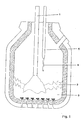
- a blowing lance 1 is arranged, which blows oxygen into the slag 2 or molten steel 3.
- a sublance 4 with an immersion probe 5 is arranged. The sublance 4 moves from above into the converter oven until the immersion probe 5 dips into the molten steel 3. After the measurement, it is pulled up, the immersion probe 5 is destroyed. If it is designed as a measuring probe, the measurement has taken place during the immersion in molten steel 3. A sample chamber disposed in the immersion probe 5 was filled in the molten steel 3. The sample chamber is removed from the discarded immersion probe 5 and the sample can be evaluated. For the next measurement, another immersion probe 5 is removed from a depot, usually mechanically attached to the sublance 4 and introduced for measurement in the converter furnace.
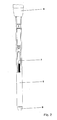
- FIG. 2 shows the immersion probe 5 arranged at the lower end of the sublance 4.
- the immersion probe 5 has a dipping end which is protected against the slag layer 2 lying on the molten steel 3 by a cap 6, which is only exposed to the sensor or the specimen chamber after immersion in the molten steel 3 releases.
- the immersion probe 5 is attached to the sublance 4 by means of the lance holder. By means of a contact piece arranged on the lance holder 7, the signal lines of the immersion probe 5 are contacted, so that the measurement signals can be passed through the sublance 4 to an evaluation unit.
- FIG. 3 shows the lance holder.
- the lance holder is a reusable part of the sublance 4. It serves to hold the immersion probe 5 and as a contact connection with the immersion probe 5.
- the lance holder is connected to the water-cooled part of the sublance 4. The water cooling is not explained in detail in the figures. It is well known from the prior art (for example, EP 69 433).
- the lance holder is arranged with its upper part 8 rigidly in the sublance 4 and its lower part, starting approximately from the parting line 9 in the immersion probe 5. In this case, the contact piece 7 ensures electrical contact with the signal lines of the immersion probe 5.
- the derivation of the electrical signals and forwarding to a measuring or evaluation station is carried out by the lance cable 10, which is arranged at the upper end of the lance holder and is passed through the sublance 4.
- a rubber ring 11 is arranged in the upper part of the lance holder.
- the rubber ring 11 allows both a radial and an axial movement of the lower part of the lance holder relative to the upper part 8.
- the rubber ring 11 is held by a screw 16 against a stop 17.
- the screw 16 has a through hole 18 in the axial direction, which is flared in the direction of the contact piece 7.
- the contact piece 7 having part of the lance holder has a sealing sleeve 12 into which a guide tube 13 protrudes.
- a coil spring 14 is arranged in the longitudinal direction between the guide tube 13 and an inner stop surface of the sealing sleeve 12.
- the spring 14 preferably has a spring tension which is greater than the attachment force of the contact piece 7 on the so-called connector within the immersion probe 5, with its Help the signal lines are contacted with the contact piece.
- the contact piece 7 is connected.
- the contact piece 7 is arranged both longitudinally and radially movable to the sublance 4 and can therefore also be connected to the signal lines of the immersion probe when the lower, the lance holder-bearing end of the sublance 4 is slightly bent.
- a secure mechanical mounting of the immersion probe 5 in any conceivable case is possible.
Landscapes
- Engineering & Computer Science (AREA)
- Chemical & Material Sciences (AREA)
- Life Sciences & Earth Sciences (AREA)
- General Physics & Mathematics (AREA)
- General Engineering & Computer Science (AREA)
- Physics & Mathematics (AREA)
- Health & Medical Sciences (AREA)
- Mechanical Engineering (AREA)
- Pathology (AREA)
- Immunology (AREA)
- General Health & Medical Sciences (AREA)
- Biochemistry (AREA)
- Analytical Chemistry (AREA)
- Materials Engineering (AREA)
- Manufacturing & Machinery (AREA)
- Metallurgy (AREA)
- Organic Chemistry (AREA)
- Hydrology & Water Resources (AREA)
- Food Science & Technology (AREA)
- Medicinal Chemistry (AREA)
- Investigating And Analyzing Materials By Characteristic Methods (AREA)
- Carbon Steel Or Casting Steel Manufacturing (AREA)
Abstract
Description
- Die Erfindung betrifft eine Vorrichtung zur Durchführung von Messungen und/oder Probennahmen in Metallschmelzen mit einer Sublanze, die einen Sublanzenkörper aufweist, an dessen einem Ende ein Lanzenhalter zur Aufnahme einer Eintauchsonde angeordnet ist.
- Derartige Vorrichtungen sind den Fachleuten hinreichend bekannt. Sie dienen der Messung bzw. Probennahme in Metallschmelzen. Derartige Probennahmen werden zum Teil automatisiert, wobei eine Sublanze in einen Schmelzbehälter eingetaucht wird zur Messung, danach wird die an der Sublanze angeordnete Eintauchsonde, da sie verbraucht ist, verworfen und eine neue Eintauchsonde auf die Sublanze aufgesteckt. Um diesen Vorgang zu automatisieren, muss die Sublanze exakt über einen Sondendepot positionierbar sein. Inder Praxis zeigt es sich jedoch, dass wegen der Belastungen, denen eine Sublanze während des Gebrauchs ausgesetzt ist, diese Sublanzen geringfügig verbogen werden, so dass der Lanzenhalter nicht mehr exakt über einer Eintauchsonde platzierbar ist und diese nicht einwandfrei aufnehmen kann. Die auf die Sublanzen aufgesteckten Eintauchsonden weisen nicht exakt die gleiche Länge auf. Insbesondere der im Trägerrohr untergebrachte Kontaktteil ist für den Gegenkontakt in der Sublanze nicht stets in der gleichen Tiefe erreichbar. Dazu werden sich häufig Spritzer der Metallschmelze an Teilen der Sublanze anlagern, die für die Kontaktierung frei bleiben müssen, so dass ein einwandfreies Aufstecken der Eintauchsonden nicht möglich ist. Dadurch kann der gesamte Stahlherstellungsprozess gestört werden.
- Sublanzen sind beispielsweise aus EP 69 433 bekannt. Hier wird versucht, der Verformung der Sublanze während des Betriebes durch Drehen der Sublanze entgegenzuwirken. Die Anordnung und Funktion von Sublanzen ist des weiteren in DE 43 06 332 A1 beschrieben. Hier ist auch der Wechselprozess der Probensonden offenbart. Eine weitere Sublanze ist aus EP 143 498 A2 bekannt. Die hier dargestellte Sublanze weist an Verbindungsstellen eine Abdichtung, beispielsweise einen Gummiring auf, der verhindert, dass in die Mechanik flüssiges Metall eindringen kann.
- Der Erfindung liegt die Aufgabe zugrunde, die bekannten Sublanzen zu verbessern und insbesondere die Ausfallsicherheit im automatischen Betrieb zu erhöhen.
Die Aufgabe wird für die eingangs charakterisierte Erfindung dadurch gelöst, dass an dem Lanzenhalter ein Kontaktstück angeordnet ist zur Kontaktierung von Signalleitungen der Eintauchsonde, weiterhin dadurch, dass der Sublanzenkörper mit dem Lanzenhalter oder einem Teil davon beweglich verbunden ist und/oder dass der Lanzenhalter mehrere gegeneinander bewegliche Teile aufweist, wobei das Kontaktstück beweglich zur Sublanze, insbesondere zum Sublanzenkörper, angeordnet ist. Die Sublanze wird auf das Oberteil der Lanzenhalterung fest aufgeschoben und vorzugsweise unbeweglich gehalten. Das untere Teil der Lanzenhalterung mit dem Kontaktstück ist beweglich, damit die Sonde in Kontakt gebracht werden kann mit dem Kontaktstück. Dadurch kann sich die Lanzenhalterung der Lage des bereit gestellten Sensors anpassen, so dass ein ausreichender Kontakt auch bei leicht verbogenen Bauteilen oder dann möglich ist, wenn Metallschmelze an der Sublanze anhaftet. Unterschiedliche Einstecktiefen der Sublanze in das Trägerrohr der Eintauchsonde werden auf diese Weise ebenfalls ausgeglichen. Vorzugsweise sind der Sublanzenkörper mit dem Lanzenhalter und/oder die Teile des Lanzenhalters in Achsrichtung und/oder radial beweglich angeordnet. Des weiteren ist es vorteilhaft, dass die axiale Beweglichkeit und die radiale Beweglichkeit durch voneinander verschiedene Paare von Verbindungsteilen realisiert sind, um eine höchstmögliche Flexibilität und Anpassungsfähigkeit zu erhalten. Gerade bei Anhaften von Metallschmelze an der Sublanze oder bei unterschiedlich angeordneten Kontaktteilen der Eintauchsonde ist eine axiale Beweglichkeit von Bedeutung, um die korrekte Kontaktierung der Eintauchsonde zu gewährleisten. Insbesondere ist es vorteilhaft, dass die Beweglichkeit durch zwischen starren Teilen angeordnete elastische Teile realisiert ist, wobei die elastischen Teile als Feder, beispielsweise als Schraubenfeder oder als elastischer Ring ausgebildet sein können. Des weiteren ist es zweckmäßig, dass ein Teil des Lanzenhalters eine Aufnahmebohrung aufweist, in der ein Zapfen eines zweiten Teils des Lanzenhalters axial beweglich angeordnet ist, wobei zwischen dem ersten und dem zweiten Teil des Lanzenhalters eine Schraubenfeder angeordnet ist. Dazu ist es von Vorteil, dass die Schraubenfeder zwischen einer an der Stirnseite oder an der Umfangsfläche des Zapfens angeordneten Anschlagsfläche und einer an oder in der Bohrung angeordneten zweiten Anschlagsfläche angeordnet ist. Die die Beweglichkeit gewährleistenden Bauteile sind dadurch selbst geschützt. - Zweckmäßigerweise weist ein Teil des Lanzenhalters eine Aufnahmebohrung auf, in der ein Zapfen eines zweiten Teils des Lanzenhalters radial beweglich angeordnet ist, wobei zwischen dem ersten und dem zweiten Teil des Lanzenhalters mindestens ein elastischer Ring angeordnet ist. Der elastische Ring kann vorteilhafterweise in radialer Richtung zwischen den beiden Teilen des Lanzenhalters angeordnet sein.
- Nachfolgend wird ein Ausführungsbeispiel der Erfindung anhand einer Zeichnung beschrieben. In der Zeichnung zeigt:
- Fig. 1
- einen Konverterofen mit einer Sublanze,
- Fig. 2
- eine Sublanze mit Lanzenhalter und Eintauchsonde und
- Fig. 3
- eine Lanzenhalterung im Detail.
- In dem in Figur 1 dargestellten Konverterofen ist eine Blaslanze 1 angeordnet, die Sauerstoff in die Schlacke- 2 bzw. Stahlschmelze 3 bläst. Daneben ist eine Sublanze 4 mit einer Eintauchsonde 5 angeordnet. Die Sublanze 4 fährt von oben in den Konverterofen hinein bis die Eintauchsonde 5 in die Stahlschmelze 3 eintaucht. Nach der Messung wird sie emporgezogen, die Eintauchsonde 5 ist zerstört. Wenn sie als Messsonde ausgelegt ist, ist die Messung während des Eintauchens in der Stahlschmelze 3 erfolgt. Eine in der Eintauchsonde 5 angeordnete Probenkammer wurde in der Stahlschmelze 3 gefüllt. Die Probenkammer wird der abgeworfenen Eintauchsonde 5 entnommen und die Probe kann ausgewertet werden. Für die nächste Messung wird eine weitere Eintauchsonde 5 aus einem Depot entnommen, in der Regel maschinell auf die Sublanze 4 aufgesteckt und zur Messung in den Konverterofen eingeführt.
- Figur 2 zeigt die am unteren Ende der Sublanze 4 angeordnete Eintauchsonde 5. Die Eintauchsonde 5 weist ein Eintauchende auf, welches gegen die auf der Stahlschmelze 3 aufliegende Schlackeschicht 2 durch eine Kappe 6 geschützt ist, die dem Sensor bzw. die Probenkammer erst nach Eintauchen in die Stahlschmelze 3 freigibt. Die Eintauchsonde 5 ist mittels des Lanzenhaltes an der Sublanze 4 befestigt. Mittels eines an dem Lanzenhalter angeordneten Kontaktstück 7 werden die Signalleitungen der Eintauchsonde 5 kontaktiert, so dass die Messsignale durch die Sublanze 4 hindurch zu einer Auswerteeinheit geführt werden können.
- In Figur 3 ist der Lanzenhalter dargestellt. Der Lanzenhalter ist ein wiederbenutzbares Teil der Sublanze 4. Er dient zur Halterung der Eintauchsonde 5 und als Kontaktverbindung mit der Eintauchsonde 5. Der Lanzenhalter ist mit dem wassergekühlten Teil der Sublanze 4 verbunden. Die Wasserkühlung ist in den Figuren nicht näher erläutert. Sie ist aus dem Stand der Technik (beispielsweise EP 69 433) hinreichend bekannt. Der Lanzenhalter ist mit seinem oberen Teil 8 starr in der Sublanze 4 angeordnet und sein unterer Teil, beginnend etwa ab der Trennlinie 9 in der Eintauchsonde 5. Dabei stellt das Kontaktstück 7 die elektrische Kontaktierung mit den Signalleitungen der Eintauchsonde 5 sicher. Die Ableitung der elektrischen Signale und Weiterleitung an eine Mess- oder Auswertestation erfolgt durch das Lanzenkabel 10, welches am oberen Ende des Lanzenhalters angeordnet ist und durch die Sublanze 4 hindurchgeführt wird. Im oberen Bereich des Lanzenhalters ist ein Gummiring 11 angeordnet. Der Gummiring 11 ermöglicht sowohl eine radiale als auch eine axiale Bewegung des unteren Teils des Lanzenhalters gegenüber dem Oberteil 8. Der Gummiring 11 ist mittels einer Schraube 16 gegen einen Anschlag 17 gehalten. Die Schraube 16 weist in axialer Richtung ein durchgehendes Loch 18 auf, das in Richtung Kontaktstück 7 konisch erweitert ist. Dadurch ist das Oberteil 8 der Sublanze 4 gegenüber dem unteren Teil radial und geringfügig auch axial beweglich. Statt eines Gummirings 11 kann auch eine Metallfeder, beispielsweise eine Schraubenfeder verwendet werden. Der untere, das Kontaktstück 7 aufweisende Teil des Lanzenhalters weist eine Dichtungshülse 12 auf, in die ein Führungsrohr 13 hineinragt. In Längsrichtung zwischen dem Führungsrohr 13 und einer inneren Anschlagsfläche der Dichtungshülse 12 ist eine Schraubenfeder 14 angeordnet. Dadurch ist eine Beweglichkeit des Kontaktstücks 7 mit der Dichtungshülse 12 längs des Führungsrohrs 13 gewährleistet. Diese Beweglichkeit sichert auch bei unterschiedlicher Länge verschiedener Eintauchsensoren 5, die auf den Lanzenhalter aufgesteckt werden, stets eine sicheren Kontakt zwischen den Signalleitungen des Eintauchsensors 5 und dem Kontaktstück 7. Ein sicherer Kontakt ist auch dann gewährleistet, wenn sich auf den Lanzenhalter Verunreinigungen, wie Metallschmelze oder Schlacke festgesetzt haben. Dies kann im oberen Teil des Lanzenhalters dort passieren, wo die Sublanze 4 und die Eintauchsonde 5 aneinander stoßen. Auch in einem solchen Fall der Verunreinigung ist durch die Feder 14 ein zuverlässiger Kontakt zwischen dem Kontaktstück 7 und den Signalleitungen der Eintauchsonde 5 gewährleistet. Die Feder 14 weist vorzugsweise eine Federspannung auf, die größer ist als die Aufsteckkraft des Kontaktstückes 7 auf den sogenannten Konnektor innerhalb der Eintauchsonde 5, mit dessen Hilfe die Signalleitungen mit dem Kontaktstück kontaktiert werden. Innerhalb des Führungsrohrs 13 können Kupplungselemente 15 vorgesehen sein, über die das Lanzenkabel 10 mit dem
- Kontaktstück 7 verbunden wird. Auf die gezeigte Weise ist das Kontaktstück 7 sowohl längs als auch radial beweglich zur Sublanze 4 angeordnet und kann daher mit den Signalleitungen der Eintauchsonde auch dann verbunden werden, wenn das untere, den Lanzenhalter tragende Ende der Sublanze 4 leicht gebogen ist. Ebenso ist eine sichere mechanische Halterung der Eintauchsonde 5 in jedem praktisch denkbaren Fall möglich.
Claims (9)
- Vorrichtung zur Durchführung von Messungen und/oder Probennahmen in Metallschmelzen mit einer Sublanze, die einen Sublanzenkörper aufweist, an dessen einem Ende ein Lanzenhalter zur Aufnahme einer Eintauchsonde angeordnet ist, dadurch gekennzeichnet, dass an dem Lanzenhalter ein Kontaktstück angeordnet ist zur Kontaktierung von Signalleitungen der Eintauchsonde, weiterhin gekennzeichnet dadurch, dass der Sublanzenkörper mit dem Lanzenhalter beweglich verbunden ist und/oder der Lanzenhalter mehrere gegeneinander bewegliche Teile aufweist, wobei das Kontaktstück beweglich zum Sublanzenkörper angeordnet ist.
- Vorrichtung nach Anspruch 1, dadurch gekennzeichnet, dass der Sublanzenkörper mit dem Lanzenhalter und/oder die Teile des Lanzenhalters in Achsrichtung und/oder radial beweglich angeordnet sind.
- Vorrichtung nach Anspruch 2, dadurch gekennzeichnet, dass die axiale Beweglichkeit und die radiale Beweglichkeit durch voneinander verschiedene Paare von Verbindungsteilen realisiert sind.
- Vorrichtung nach einem der Ansprüche 1 bis 3, dadurch gekennzeichnet, dass die Beweglichkeit durch zwischen starren Teilen angeordnete elastische Teile realisiert ist.
- Vorrichtung nach Anspruch 4, dadurch gekennzeichnet, dass die elastischen Teile als Schraubenfeder oder elastischer Ring ausgebildet sind.
- Vorrichtung nach einem der Ansprüche 1 bis 5, dadurch gekennzeichnet, dass ein Teil des Lanzenhalters eine Aufnahmebohrung aufweist, in der ein Zapfen eines zweiten Teils des Lanzenhalters axial beweglich angeordnet ist, wobei zwischen dem ersten und dem zweiten Teil des Lanzenhalters eine Schraubenfeder angeordnet ist.
- Vorrichtung nach Anspruch 6, dadurch gekennzeichnet, dass die Schraubenfeder zwischen einer an der Stirnseite oder an der Umfangsfläche des Zapfens angeordneten Anschlagsfläche und einer an oder in der Bohrung angeordneten Anschlagsfläche angeordnet ist.
- Vorrichtung nach einem der Ansprüche 1 bis 7, dadurch gekennzeichnet, dass ein Teil des Lanzenhalters eine Aufnahmebohrung aufweist, in der ein Zapfen eines zweiten Teils des Lanzenhalters radial beweglich angeordnet ist, wobei zwischen dem ersten und dem zweiten Teil des Lanzenhalters mindestens ein elastischer Ring angeordnet ist.
- Vorrichtung nach Anspruch 8, dadurch gekennzeichnet, dass der elastische Ring in radialer Richtung zwischen den beiden Teilen des Lanzenhalters angeordnet ist.
Priority Applications (1)
| Application Number | Priority Date | Filing Date | Title |
|---|---|---|---|
| PL05012272T PL1614758T3 (pl) | 2004-06-16 | 2005-06-08 | Urządzenie do przeprowadzania pomiarów i/lub pobierania próbek w stopionych metalach |
Applications Claiming Priority (1)
| Application Number | Priority Date | Filing Date | Title |
|---|---|---|---|
| DE102004028789A DE102004028789B3 (de) | 2004-06-16 | 2004-06-16 | Vorrichtung zur Durchführung von Messungen und/oder Probennahmen in Metallschmelzen |
Publications (3)
| Publication Number | Publication Date |
|---|---|
| EP1614758A2 true EP1614758A2 (de) | 2006-01-11 |
| EP1614758A3 EP1614758A3 (de) | 2006-03-15 |
| EP1614758B1 EP1614758B1 (de) | 2007-11-21 |
Family
ID=35310894
Family Applications (1)
| Application Number | Title | Priority Date | Filing Date |
|---|---|---|---|
| EP05012272A Expired - Lifetime EP1614758B1 (de) | 2004-06-16 | 2005-06-08 | Vorrichtung zur Durchführung von Messungen und/oder Probenahmen in Metallschmelzen |
Country Status (12)
| Country | Link |
|---|---|
| US (1) | US7370544B2 (de) |
| EP (1) | EP1614758B1 (de) |
| JP (1) | JP4571018B2 (de) |
| KR (1) | KR101012039B1 (de) |
| CN (1) | CN100541164C (de) |
| AU (1) | AU2005202487B2 (de) |
| BR (1) | BRPI0502374B1 (de) |
| CA (1) | CA2508583C (de) |
| DE (2) | DE102004028789B3 (de) |
| ES (1) | ES2294595T3 (de) |
| PL (1) | PL1614758T3 (de) |
| ZA (1) | ZA200504884B (de) |
Cited By (3)
| Publication number | Priority date | Publication date | Assignee | Title |
|---|---|---|---|---|
| EP1813940A2 (de) | 2006-01-26 | 2007-08-01 | Heraeus Electro-Nite International N.V. | Vorrichtung zum Bestimmen einer Kenngrösse einer Metallschmelze oder einer auf der Metallschmelze aufliegenden Schlackeschicht |
| WO2012113498A1 (de) | 2011-02-23 | 2012-08-30 | Heraeus Electro-Nite International N.V. | Sensoranordnung zur messung von parametern in schmelzen |
| EP3026431A1 (de) * | 2014-11-27 | 2016-06-01 | Primetals Technologies Austria GmbH | Mess- und Probeentnahmelanze, ein Verfahren sowie eine Ablagevorrichtung zum Einlegen einer Mess- und Probeentnahmelanze |
Families Citing this family (14)
| Publication number | Priority date | Publication date | Assignee | Title |
|---|---|---|---|---|
| DE102006047765B3 (de) * | 2006-10-06 | 2007-12-20 | Heraeus Electro-Nite International N.V. | Eintauchlanze für die Analyse von Schmelzen und Flüssigkeiten |
| DE102010001669A1 (de) * | 2010-02-08 | 2011-08-11 | Siemens Aktiengesellschaft, 80333 | Vorrichtung zur Erfassung mindestens einer Messgröße an einem Ofen, sowie Ofen |
| DE102010024282A1 (de) * | 2010-06-18 | 2011-12-22 | Heraeus Electro-Nite International N.V. | Messsonden zur Messung und Probennahme mit einer Metallschmelze |
| DE102010053710B4 (de) * | 2010-12-07 | 2012-12-27 | Heraeus Electro-Nite International N.V. | Verfahren und Vorrichtung zur Analyse von Proben von Metallschmelzen |
| DE102014016902A1 (de) | 2014-11-17 | 2016-05-19 | Minkon GmbH | Sonde für eine Sublanze und Sublanze |
| BR102014033086A2 (pt) | 2014-12-30 | 2016-10-18 | Ecil Met Tec Ltda | sonda de imersão e conjunto de sublança de imersão e sonda de imersão para um forno conversor |
| EP3051262B1 (de) * | 2015-01-28 | 2018-07-25 | Heraeus Electro-Nite International N.V. | Zufuhrvorrichtung für eine optische Faser zur Messung der Temperatur einer Schmelze |
| KR102512878B1 (ko) * | 2015-12-24 | 2023-03-23 | 주식회사 포스코 | 샘플러 보호캡 및 용강 샘플러 |
| EP3567370A1 (de) * | 2018-05-08 | 2019-11-13 | Primetals Technologies Austria GmbH | Lanzensonde mit abgabe von referenzspannungen |
| CN108746516B (zh) * | 2018-06-07 | 2019-11-08 | 武汉科技大学 | 一种钢包测温取样装置 |
| EP3588052B1 (de) * | 2018-06-29 | 2021-03-31 | Heraeus Electro-Nite International N.V. | Tauchfühler und messsystem zur verwendung in einem konverter stahlverfahren |
| CN108917416B (zh) * | 2018-07-10 | 2023-07-25 | 西安航空制动科技有限公司 | 一种具有防卡抗污染功能的真空炉升降移动装置 |
| US11739391B2 (en) * | 2020-01-09 | 2023-08-29 | Vesuvius Refratarios Ltda. | Lance for use in metal production and casting installations |
| CN116399633B (zh) * | 2023-06-05 | 2023-08-29 | 湖南普拉斯智能科技有限公司 | 一种适用于钢厂场地条件受限的测温取样装置 |
Family Cites Families (28)
| Publication number | Priority date | Publication date | Assignee | Title |
|---|---|---|---|---|
| DE1921322A1 (de) * | 1968-05-15 | 1969-12-04 | Voest Ag | Verfahren zur kontinuierlichen Messung der Temperatur von Metallbaedern und Messlanze zur Durchfuehrung des Verfahrens |
| US3698954A (en) * | 1968-12-09 | 1972-10-17 | Leeds & Northrup Co | Expendable immersion thermocouple assembly |
| DE2718860A1 (de) * | 1974-10-09 | 1978-11-02 | Krupp Gmbh | Messkartuschenhandhabungseinrichtung |
| JPS5379703A (en) * | 1976-12-24 | 1978-07-14 | Kawasaki Steel Co | Rapid detachable joint for sublance holder |
| JPS53104295A (en) * | 1977-02-24 | 1978-09-11 | Nippon Kokan Kk | Sampling method through subblance |
| US4141249A (en) * | 1977-03-14 | 1979-02-27 | Nippon Kokan Kabushiki Kaisha | Sub-lance assembly for sampling and temperature-measuring of molten metal during refining |
| JPS6059965B2 (ja) * | 1979-03-28 | 1985-12-27 | 日本鋼管株式会社 | 回転式サブランスの回転装置 |
| NL8103306A (nl) | 1981-07-10 | 1983-02-01 | Estel Hoogovens Bv | Hulplans voor het uitvoeren van metingen en/of monsternames in een metallurgische oven en werkwijze voor het gebruik van deze hulplans. |
| AT387855B (de) * | 1982-12-09 | 1989-03-28 | Voest Alpine Ag | Sondenmanipulator |
| US4566343A (en) * | 1983-11-28 | 1986-01-28 | Electro-Nite Co. | Sampling and/or measuring apparatus for immersion in molten metal |
| DE3641225A1 (de) * | 1985-12-04 | 1987-06-11 | Electro Nite | Verfahren und vorrichtung zur messung bzw. probenahme in metallschmelzen und dabei gebrauchte lanze |
| JPS6473014A (en) * | 1987-09-16 | 1989-03-17 | Nippon Kokan Kk | Sub-lancing method |
| JPH01132711A (ja) * | 1987-11-18 | 1989-05-25 | Nkk Corp | サブランス |
| US4912989A (en) * | 1988-10-27 | 1990-04-03 | Electro-Nite International | Shock absorbing immersion probe |
| JP2706732B2 (ja) * | 1989-04-03 | 1998-01-28 | 川惣電機工業株式会社 | 溶融金属の試料採取及び/又は温度測定用プローブ |
| JP2706737B2 (ja) * | 1989-04-03 | 1998-01-28 | 川惣電機工業株式会社 | 溶融金属の試料採取及び/又は温度測定用プローブ |
| DE4303688C3 (de) * | 1993-02-09 | 2000-06-15 | Heraeus Electro Nite Int | Probennehmer für Metallschmelze |
| DE4306332A1 (de) * | 1993-02-24 | 1994-08-25 | Mannesmann Ag | Vorrichtung zum Wechseln von Meß- und/oder Probensonden |
| JP3176006B2 (ja) * | 1994-01-28 | 2001-06-11 | 日本鋼管株式会社 | スリーブ付きプローブおよびプローブ交換装置 |
| DE19623683C1 (de) * | 1996-06-14 | 1997-11-13 | Heraeus Electro Nite Int | Vorrichtung zur Durchführung von elektrochemischen Messungen in Glas- oder Salzschmelzen |
| JP3602939B2 (ja) * | 1996-11-19 | 2004-12-15 | 松下電器産業株式会社 | 半導体記憶装置 |
| DE19652596C2 (de) * | 1996-12-18 | 1999-02-25 | Heraeus Electro Nite Int | Verfahren und Tauchmeßfühler zum Messen einer elektrochemischen Aktivität |
| JP4531150B2 (ja) * | 1998-11-09 | 2010-08-25 | Okiセミコンダクタ株式会社 | 半導体記憶装置 |
| JP4399927B2 (ja) * | 1998-11-17 | 2010-01-20 | ヘレウス・エレクトロナイト株式会社 | スラグ中の酸素分圧測定装置およびその測定方法 |
| JP3697956B2 (ja) * | 1999-07-16 | 2005-09-21 | Jfeスチール株式会社 | 溶融金属の特性測定用プローブ及び該プローブのサブランスへの装着方法 |
| SE0104252D0 (sv) * | 2001-12-17 | 2001-12-17 | Sintercast Ab | New device |
| DE10241833A1 (de) * | 2002-09-09 | 2004-03-18 | Mettler-Toledo Gmbh | Wechselarmatur mit einem Sensor |
| DE102005060492B3 (de) * | 2005-12-15 | 2007-05-24 | Heraeus Electro-Nite International N.V. | Messsonde zur Messung in Metall- oder Schlackeschmelzen |
-
2004
- 2004-06-16 DE DE102004028789A patent/DE102004028789B3/de not_active Expired - Fee Related
-
2005
- 2005-05-30 CA CA2508583A patent/CA2508583C/en not_active Expired - Fee Related
- 2005-06-08 ES ES05012272T patent/ES2294595T3/es not_active Expired - Lifetime
- 2005-06-08 PL PL05012272T patent/PL1614758T3/pl unknown
- 2005-06-08 AU AU2005202487A patent/AU2005202487B2/en not_active Ceased
- 2005-06-08 EP EP05012272A patent/EP1614758B1/de not_active Expired - Lifetime
- 2005-06-08 DE DE502005002019T patent/DE502005002019D1/de not_active Expired - Lifetime
- 2005-06-14 JP JP2005173564A patent/JP4571018B2/ja not_active Expired - Fee Related
- 2005-06-14 KR KR1020050050711A patent/KR101012039B1/ko not_active Expired - Fee Related
- 2005-06-15 CN CNB2005100795508A patent/CN100541164C/zh not_active Expired - Lifetime
- 2005-06-15 ZA ZA200504884A patent/ZA200504884B/en unknown
- 2005-06-15 BR BRPI0502374A patent/BRPI0502374B1/pt not_active IP Right Cessation
- 2005-06-15 US US11/153,277 patent/US7370544B2/en not_active Expired - Lifetime
Cited By (7)
| Publication number | Priority date | Publication date | Assignee | Title |
|---|---|---|---|---|
| EP1813940A2 (de) | 2006-01-26 | 2007-08-01 | Heraeus Electro-Nite International N.V. | Vorrichtung zum Bestimmen einer Kenngrösse einer Metallschmelze oder einer auf der Metallschmelze aufliegenden Schlackeschicht |
| EP1813940A3 (de) * | 2006-01-26 | 2008-04-02 | Heraeus Electro-Nite International N.V. | Vorrichtung zum Bestimmen einer Kenngrösse einer Metallschmelze oder einer auf der Metallschmelze aufliegenden Schlackeschicht |
| WO2012113498A1 (de) | 2011-02-23 | 2012-08-30 | Heraeus Electro-Nite International N.V. | Sensoranordnung zur messung von parametern in schmelzen |
| BE1020060A3 (nl) * | 2011-02-23 | 2013-04-02 | Heraeus Electro Nite Int | Sensoropstelling voor de meting van parameters in smelt. |
| US9366578B2 (en) | 2011-02-23 | 2016-06-14 | Heraeus Electro-Nite International N.V. | Sensor arrangement for the measuring of parameters in melted material |
| EP3026431A1 (de) * | 2014-11-27 | 2016-06-01 | Primetals Technologies Austria GmbH | Mess- und Probeentnahmelanze, ein Verfahren sowie eine Ablagevorrichtung zum Einlegen einer Mess- und Probeentnahmelanze |
| WO2016083006A1 (de) * | 2014-11-27 | 2016-06-02 | Primetals Technologies Austria GmbH | Mess- und probeentnahmelanze, ein verfahren sowie eine ablagevorrichtung zum einlegen einer mess- und probeentnahmelanze |
Also Published As
| Publication number | Publication date |
|---|---|
| BRPI0502374B1 (pt) | 2019-01-22 |
| BRPI0502374A (pt) | 2006-02-07 |
| DE502005002019D1 (de) | 2008-01-03 |
| EP1614758A3 (de) | 2006-03-15 |
| CA2508583C (en) | 2013-10-15 |
| DE102004028789B3 (de) | 2006-01-05 |
| EP1614758B1 (de) | 2007-11-21 |
| CN1712923A (zh) | 2005-12-28 |
| JP2006003356A (ja) | 2006-01-05 |
| ZA200504884B (en) | 2006-04-26 |
| AU2005202487A1 (en) | 2006-01-12 |
| AU2005202487B2 (en) | 2007-11-15 |
| CA2508583A1 (en) | 2005-12-16 |
| JP4571018B2 (ja) | 2010-10-27 |
| CN100541164C (zh) | 2009-09-16 |
| ES2294595T3 (es) | 2008-04-01 |
| PL1614758T3 (pl) | 2008-04-30 |
| KR20060046435A (ko) | 2006-05-17 |
| US20050279183A1 (en) | 2005-12-22 |
| KR101012039B1 (ko) | 2011-02-01 |
| US7370544B2 (en) | 2008-05-13 |
Similar Documents
| Publication | Publication Date | Title |
|---|---|---|
| EP1614758B1 (de) | Vorrichtung zur Durchführung von Messungen und/oder Probenahmen in Metallschmelzen | |
| EP2525207B1 (de) | Probennehmer für die Probennahmen aus Schmelzen mit einem Schmelzpunkt größer 600°C sowie Verfahren zur Probennahme | |
| EP1813940A2 (de) | Vorrichtung zum Bestimmen einer Kenngrösse einer Metallschmelze oder einer auf der Metallschmelze aufliegenden Schlackeschicht | |
| DE202009012292U1 (de) | Temperaturfühler mit Prüfkanal | |
| EP1564536B1 (de) | Vorrichtung und Verfahren zur Messung von Temperatur in Metallschmelzen | |
| EP1813919B1 (de) | Vorrichtung zum Bestimmen einer Grenzfläche einer Schlackeschicht auf einer Metallschmelze | |
| DE102013208679A1 (de) | Messsonde zur Messung in Metall- oder Schlackeschmelzen | |
| WO2007079894A1 (de) | Konverter mit einem behälter zur aufnahme geschmolzenen metalls und einer messvorrichtung zur optischen temperaturbestimmung des geschmolzenen metalls sowie verfahren zur temperaturbestimmung in einem derartigen konverter | |
| DE2839982A1 (de) | Federnder kontaktbaustein | |
| EP2100974B1 (de) | Lanze zur aufnahme eines sensors oder probennehmers für metallschmelzen | |
| DE4402463A1 (de) | Vorrichtung zur diskontinuierlichen Erfassung der Dicke von Schichten auf einer Metallschmelze | |
| DE19848598B4 (de) | Mehrfach ummantelte Natriumleckerkennungsvorrichtung | |
| DE4038507C1 (en) | Device for remotely seating and tightening screw - includes ultrasound test head for measuring longitudinal expansion of screw shaft, used in nuclear reactor installation | |
| EP0765473B1 (de) | Verfahren zum messen einer elektrochemischen aktivität | |
| DE102005043852B3 (de) | Eintauchsonde | |
| DE3233677C1 (de) | Vorrichtung zur Probenahme von Metall und Schlacke | |
| EP1798545A1 (de) | Messsonde | |
| DE19508433C1 (de) | Modularer Halter für eine gekühlte Glasschmelz-Tauchelektrode | |
| DE202018101270U1 (de) | Sonde für eine Sublanze mit Entfernungsmesser | |
| EP2442079B1 (de) | Kontaktstift | |
| DE102004010593B4 (de) | Meßsonde und Verfahren zu deren Herstellung | |
| DE1648957C3 (de) | Probenehmer für Metallschmelzen mit Mitteln zur Feststellung der Temperatur | |
| DE102014016902A1 (de) | Sonde für eine Sublanze und Sublanze | |
| EP3649418A1 (de) | Führen einer sonde | |
| DE4407103C1 (de) | Prüfsonde zum Einfahren in einen Spalt |
Legal Events
| Date | Code | Title | Description |
|---|---|---|---|
| PUAI | Public reference made under article 153(3) epc to a published international application that has entered the european phase |
Free format text: ORIGINAL CODE: 0009012 |
|
| 17P | Request for examination filed |
Effective date: 20050613 |
|
| AK | Designated contracting states |
Kind code of ref document: A2 Designated state(s): AT BE BG CH CY CZ DE DK EE ES FI FR GB GR HU IE IS IT LI LT LU MC NL PL PT RO SE SI SK TR |
|
| AX | Request for extension of the european patent |
Extension state: AL BA HR LV MK YU |
|
| PUAL | Search report despatched |
Free format text: ORIGINAL CODE: 0009013 |
|
| AK | Designated contracting states |
Kind code of ref document: A3 Designated state(s): AT BE BG CH CY CZ DE DK EE ES FI FR GB GR HU IE IS IT LI LT LU MC NL PL PT RO SE SI SK TR |
|
| AX | Request for extension of the european patent |
Extension state: AL BA HR LV MK YU |
|
| 17Q | First examination report despatched |
Effective date: 20060905 |
|
| AKX | Designation fees paid |
Designated state(s): AT BE BG CH CY CZ DE DK EE ES FI FR GB GR HU IE IS IT LI LT LU MC NL PL PT RO SE SI SK TR |
|
| GRAP | Despatch of communication of intention to grant a patent |
Free format text: ORIGINAL CODE: EPIDOSNIGR1 |
|
| GRAS | Grant fee paid |
Free format text: ORIGINAL CODE: EPIDOSNIGR3 |
|
| GRAA | (expected) grant |
Free format text: ORIGINAL CODE: 0009210 |
|
| AK | Designated contracting states |
Kind code of ref document: B1 Designated state(s): AT BE BG CH CY CZ DE DK EE ES FI FR GB GR HU IE IS IT LI LT LU MC NL PL PT RO SE SI SK TR |
|
| REG | Reference to a national code |
Ref country code: GB Ref legal event code: FG4D Free format text: NOT ENGLISH |
|
| REG | Reference to a national code |
Ref country code: IE Ref legal event code: FG4D Free format text: LANGUAGE OF EP DOCUMENT: GERMAN |
|
| REG | Reference to a national code |
Ref country code: CH Ref legal event code: EP |
|
| REF | Corresponds to: |
Ref document number: 502005002019 Country of ref document: DE Date of ref document: 20080103 Kind code of ref document: P |
|
| GBT | Gb: translation of ep patent filed (gb section 77(6)(a)/1977) |
Effective date: 20080102 |
|
| REG | Reference to a national code |
Ref country code: SE Ref legal event code: TRGR |
|
| REG | Reference to a national code |
Ref country code: ES Ref legal event code: FG2A Ref document number: 2294595 Country of ref document: ES Kind code of ref document: T3 |
|
| REG | Reference to a national code |
Ref country code: PL Ref legal event code: T3 |
|
| PG25 | Lapsed in a contracting state [announced via postgrant information from national office to epo] |
Ref country code: LT Free format text: LAPSE BECAUSE OF FAILURE TO SUBMIT A TRANSLATION OF THE DESCRIPTION OR TO PAY THE FEE WITHIN THE PRESCRIBED TIME-LIMIT Effective date: 20071121 Ref country code: BG Free format text: LAPSE BECAUSE OF FAILURE TO SUBMIT A TRANSLATION OF THE DESCRIPTION OR TO PAY THE FEE WITHIN THE PRESCRIBED TIME-LIMIT Effective date: 20080221 Ref country code: FI Free format text: LAPSE BECAUSE OF FAILURE TO SUBMIT A TRANSLATION OF THE DESCRIPTION OR TO PAY THE FEE WITHIN THE PRESCRIBED TIME-LIMIT Effective date: 20071121 Ref country code: IS Free format text: LAPSE BECAUSE OF FAILURE TO SUBMIT A TRANSLATION OF THE DESCRIPTION OR TO PAY THE FEE WITHIN THE PRESCRIBED TIME-LIMIT Effective date: 20080321 Ref country code: PL Free format text: LAPSE BECAUSE OF FAILURE TO SUBMIT A TRANSLATION OF THE DESCRIPTION OR TO PAY THE FEE WITHIN THE PRESCRIBED TIME-LIMIT Effective date: 20071121 Ref country code: SI Free format text: LAPSE BECAUSE OF FAILURE TO SUBMIT A TRANSLATION OF THE DESCRIPTION OR TO PAY THE FEE WITHIN THE PRESCRIBED TIME-LIMIT Effective date: 20071121 |
|
| PG25 | Lapsed in a contracting state [announced via postgrant information from national office to epo] |
Ref country code: CZ Free format text: LAPSE BECAUSE OF FAILURE TO SUBMIT A TRANSLATION OF THE DESCRIPTION OR TO PAY THE FEE WITHIN THE PRESCRIBED TIME-LIMIT Effective date: 20071121 Ref country code: DK Free format text: LAPSE BECAUSE OF FAILURE TO SUBMIT A TRANSLATION OF THE DESCRIPTION OR TO PAY THE FEE WITHIN THE PRESCRIBED TIME-LIMIT Effective date: 20071121 |
|
| ET | Fr: translation filed | ||
| PG25 | Lapsed in a contracting state [announced via postgrant information from national office to epo] |
Ref country code: SK Free format text: LAPSE BECAUSE OF FAILURE TO SUBMIT A TRANSLATION OF THE DESCRIPTION OR TO PAY THE FEE WITHIN THE PRESCRIBED TIME-LIMIT Effective date: 20071121 Ref country code: RO Free format text: LAPSE BECAUSE OF FAILURE TO SUBMIT A TRANSLATION OF THE DESCRIPTION OR TO PAY THE FEE WITHIN THE PRESCRIBED TIME-LIMIT Effective date: 20071121 |
|
| PLBE | No opposition filed within time limit |
Free format text: ORIGINAL CODE: 0009261 |
|
| STAA | Information on the status of an ep patent application or granted ep patent |
Free format text: STATUS: NO OPPOSITION FILED WITHIN TIME LIMIT |
|
| PG25 | Lapsed in a contracting state [announced via postgrant information from national office to epo] |
Ref country code: PT Free format text: LAPSE BECAUSE OF FAILURE TO SUBMIT A TRANSLATION OF THE DESCRIPTION OR TO PAY THE FEE WITHIN THE PRESCRIBED TIME-LIMIT Effective date: 20080421 |
|
| REG | Reference to a national code |
Ref country code: IE Ref legal event code: FD4D |
|
| 26N | No opposition filed |
Effective date: 20080822 |
|
| PG25 | Lapsed in a contracting state [announced via postgrant information from national office to epo] |
Ref country code: IE Free format text: LAPSE BECAUSE OF FAILURE TO SUBMIT A TRANSLATION OF THE DESCRIPTION OR TO PAY THE FEE WITHIN THE PRESCRIBED TIME-LIMIT Effective date: 20071121 |
|
| BERE | Be: lapsed |
Owner name: HERAEUS ELECTRO-NITE INTERNATIONAL N.V. Effective date: 20080630 |
|
| PG25 | Lapsed in a contracting state [announced via postgrant information from national office to epo] |
Ref country code: GR Free format text: LAPSE BECAUSE OF FAILURE TO SUBMIT A TRANSLATION OF THE DESCRIPTION OR TO PAY THE FEE WITHIN THE PRESCRIBED TIME-LIMIT Effective date: 20080222 Ref country code: MC Free format text: LAPSE BECAUSE OF NON-PAYMENT OF DUE FEES Effective date: 20080630 |
|
| PG25 | Lapsed in a contracting state [announced via postgrant information from national office to epo] |
Ref country code: BE Free format text: LAPSE BECAUSE OF NON-PAYMENT OF DUE FEES Effective date: 20080630 |
|
| PG25 | Lapsed in a contracting state [announced via postgrant information from national office to epo] |
Ref country code: EE Free format text: LAPSE BECAUSE OF FAILURE TO SUBMIT A TRANSLATION OF THE DESCRIPTION OR TO PAY THE FEE WITHIN THE PRESCRIBED TIME-LIMIT Effective date: 20071121 |
|
| PG25 | Lapsed in a contracting state [announced via postgrant information from national office to epo] |
Ref country code: CY Free format text: LAPSE BECAUSE OF FAILURE TO SUBMIT A TRANSLATION OF THE DESCRIPTION OR TO PAY THE FEE WITHIN THE PRESCRIBED TIME-LIMIT Effective date: 20071121 |
|
| REG | Reference to a national code |
Ref country code: CH Ref legal event code: PL |
|
| PG25 | Lapsed in a contracting state [announced via postgrant information from national office to epo] |
Ref country code: LI Free format text: LAPSE BECAUSE OF NON-PAYMENT OF DUE FEES Effective date: 20090630 Ref country code: CH Free format text: LAPSE BECAUSE OF NON-PAYMENT OF DUE FEES Effective date: 20090630 |
|
| PG25 | Lapsed in a contracting state [announced via postgrant information from national office to epo] |
Ref country code: LU Free format text: LAPSE BECAUSE OF NON-PAYMENT OF DUE FEES Effective date: 20080608 Ref country code: HU Free format text: LAPSE BECAUSE OF FAILURE TO SUBMIT A TRANSLATION OF THE DESCRIPTION OR TO PAY THE FEE WITHIN THE PRESCRIBED TIME-LIMIT Effective date: 20080522 |
|
| REG | Reference to a national code |
Ref country code: DE Ref legal event code: R082 Ref document number: 502005002019 Country of ref document: DE Representative=s name: BRAND, NORMEN, DR. RER. NAT., DE Ref country code: DE Ref legal event code: R082 Ref document number: 502005002019 Country of ref document: DE Representative=s name: BRAND, NORMEN, DIPL.-CHEM. UNIV. DR. RER. NAT., DE |
|
| REG | Reference to a national code |
Ref country code: FR Ref legal event code: PLFP Year of fee payment: 12 |
|
| REG | Reference to a national code |
Ref country code: FR Ref legal event code: PLFP Year of fee payment: 13 |
|
| PGFP | Annual fee paid to national office [announced via postgrant information from national office to epo] |
Ref country code: ES Payment date: 20170725 Year of fee payment: 13 |
|
| REG | Reference to a national code |
Ref country code: FR Ref legal event code: PLFP Year of fee payment: 14 |
|
| REG | Reference to a national code |
Ref country code: ES Ref legal event code: FD2A Effective date: 20190916 |
|
| PG25 | Lapsed in a contracting state [announced via postgrant information from national office to epo] |
Ref country code: ES Free format text: LAPSE BECAUSE OF NON-PAYMENT OF DUE FEES Effective date: 20180609 |
|
| PG25 | Lapsed in a contracting state [announced via postgrant information from national office to epo] |
Ref country code: PL Free format text: LAPSE BECAUSE OF NON-PAYMENT OF DUE FEES Effective date: 20180608 |
|
| PGFP | Annual fee paid to national office [announced via postgrant information from national office to epo] |
Ref country code: FR Payment date: 20210622 Year of fee payment: 17 Ref country code: NL Payment date: 20210618 Year of fee payment: 17 Ref country code: IT Payment date: 20210625 Year of fee payment: 17 |
|
| PGFP | Annual fee paid to national office [announced via postgrant information from national office to epo] |
Ref country code: SE Payment date: 20210618 Year of fee payment: 17 Ref country code: AT Payment date: 20210621 Year of fee payment: 17 Ref country code: TR Payment date: 20210603 Year of fee payment: 17 Ref country code: GB Payment date: 20210625 Year of fee payment: 17 |
|
| REG | Reference to a national code |
Ref country code: SE Ref legal event code: EUG |
|
| REG | Reference to a national code |
Ref country code: NL Ref legal event code: MM Effective date: 20220701 |
|
| REG | Reference to a national code |
Ref country code: AT Ref legal event code: MM01 Ref document number: 379123 Country of ref document: AT Kind code of ref document: T Effective date: 20220608 |
|
| GBPC | Gb: european patent ceased through non-payment of renewal fee |
Effective date: 20220608 |
|
| PG25 | Lapsed in a contracting state [announced via postgrant information from national office to epo] |
Ref country code: NL Free format text: LAPSE BECAUSE OF NON-PAYMENT OF DUE FEES Effective date: 20220701 |
|
| PG25 | Lapsed in a contracting state [announced via postgrant information from national office to epo] |
Ref country code: SE Free format text: LAPSE BECAUSE OF NON-PAYMENT OF DUE FEES Effective date: 20220609 Ref country code: FR Free format text: LAPSE BECAUSE OF NON-PAYMENT OF DUE FEES Effective date: 20220630 Ref country code: AT Free format text: LAPSE BECAUSE OF NON-PAYMENT OF DUE FEES Effective date: 20220608 |
|
| PG25 | Lapsed in a contracting state [announced via postgrant information from national office to epo] |
Ref country code: GB Free format text: LAPSE BECAUSE OF NON-PAYMENT OF DUE FEES Effective date: 20220608 |
|
| P01 | Opt-out of the competence of the unified patent court (upc) registered |
Effective date: 20230530 |
|
| PG25 | Lapsed in a contracting state [announced via postgrant information from national office to epo] |
Ref country code: IT Free format text: LAPSE BECAUSE OF NON-PAYMENT OF DUE FEES Effective date: 20220608 |
|
| PGFP | Annual fee paid to national office [announced via postgrant information from national office to epo] |
Ref country code: DE Payment date: 20240619 Year of fee payment: 20 |
|
| PG25 | Lapsed in a contracting state [announced via postgrant information from national office to epo] |
Ref country code: TR Free format text: LAPSE BECAUSE OF NON-PAYMENT OF DUE FEES Effective date: 20220608 |
|
| REG | Reference to a national code |
Ref country code: DE Ref legal event code: R071 Ref document number: 502005002019 Country of ref document: DE |