EP1614371B1 - Kinderhochstuhl - Google Patents
Kinderhochstuhl Download PDFInfo
- Publication number
- EP1614371B1 EP1614371B1 EP05011937A EP05011937A EP1614371B1 EP 1614371 B1 EP1614371 B1 EP 1614371B1 EP 05011937 A EP05011937 A EP 05011937A EP 05011937 A EP05011937 A EP 05011937A EP 1614371 B1 EP1614371 B1 EP 1614371B1
- Authority
- EP
- European Patent Office
- Prior art keywords
- foot
- highchair
- seat plate
- bracket
- retaining foot
- Prior art date
- Legal status (The legal status is an assumption and is not a legal conclusion. Google has not performed a legal analysis and makes no representation as to the accuracy of the status listed.)
- Expired - Lifetime
Links
Images
Classifications
-
- A—HUMAN NECESSITIES
- A47—FURNITURE; DOMESTIC ARTICLES OR APPLIANCES; COFFEE MILLS; SPICE MILLS; SUCTION CLEANERS IN GENERAL
- A47D—FURNITURE SPECIALLY ADAPTED FOR CHILDREN
- A47D15/00—Accessories for children's furniture, e.g. safety belts or baby-bottle holders
- A47D15/005—Restraining devices, e.g. safety belts, contoured cushions or side bumpers
-
- A—HUMAN NECESSITIES
- A47—FURNITURE; DOMESTIC ARTICLES OR APPLIANCES; COFFEE MILLS; SPICE MILLS; SUCTION CLEANERS IN GENERAL
- A47D—FURNITURE SPECIALLY ADAPTED FOR CHILDREN
- A47D1/00—Children's chairs
- A47D1/002—Children's chairs adjustable
-
- A—HUMAN NECESSITIES
- A47—FURNITURE; DOMESTIC ARTICLES OR APPLIANCES; COFFEE MILLS; SPICE MILLS; SUCTION CLEANERS IN GENERAL
- A47D—FURNITURE SPECIALLY ADAPTED FOR CHILDREN
- A47D1/00—Children's chairs
- A47D1/002—Children's chairs adjustable
- A47D1/004—Children's chairs adjustable in height
-
- A—HUMAN NECESSITIES
- A47—FURNITURE; DOMESTIC ARTICLES OR APPLIANCES; COFFEE MILLS; SPICE MILLS; SUCTION CLEANERS IN GENERAL
- A47D—FURNITURE SPECIALLY ADAPTED FOR CHILDREN
- A47D15/00—Accessories for children's furniture, e.g. safety belts or baby-bottle holders
- A47D15/005—Restraining devices, e.g. safety belts, contoured cushions or side bumpers
- A47D15/006—Restraining devices, e.g. safety belts, contoured cushions or side bumpers in chairs
Definitions
- the invention relates to a highchair with anti-slip, consisting of the highchair-bearing feet that receive a seat plate and a seat back on their tops.
- a highchair of the type mentioned is for example from the DE 203 15 348 U1 known.
- the slipping protection is provided in the form of a substantially vertically extending securing strap, which is in communication with a headband, wherein the headband is horizontally fastened adjustable height between mounting plates.
- the headband can always be adjusted in height, a removal of the retaining clip with seat belt is only consuming possible after a permanent assembly.
- the US-A-2,669,285 relates to a high chair with a table which is attached to a bracket, the bracket carries downwardly projecting feet to be inserted into cylindrical tube receptacles, wherein the cylindrical tube receptacles are provided on the seat plate.
- a pivoting of the bracket is not possible, as long as the bracket is firmly attached to the seat plate.
- a highchair with a table known to which a strut is attached, which in turn carries a strap.
- the bar is height adjustable attached to the strut.
- the strut can be mounted either on the table or on the seat. The bar can be adjusted vertically between the seat and the table.
- Object of the present invention is to provide a highchair, which allows for existing slipping safely in a simple way, the placement of the child in the highchair.
- the slipping protection consists of a foot and a bracket, which is preferably designed as a retaining bracket U-shaped.
- This anti-slip device is lockably secured to the seat plate and pivotable for the purpose of placing the toddler in a vertical plane relative to the seat plate.
- the bracket-retaining foot is guided on its underside through the seat plate and has a bent portion, so that when retracting the stand this is automatically pivoted together with the headband due to a corresponding curvature of the foot to the through the seat plate passing end portion.
- the foot may be provided by a lockable hinge opposite the seat plate.
- the headband is thus pivoted out of the normal anti-slip position, before the infant is placed on the chair. Subsequently, the headband is pivoted in the reverse direction in the normal operating position.
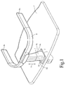
- Fig. 1 shows a partial perspective view of a highchair with a seat plate 1, which is fixed in a known manner to a pair of feet or two pairs of feet of a highchair.
- the seat plate 1 has a guide 2 which is integrated in the seat plate 1 or in an opening formed in the seat plate 1 opening or recess 3 and allows an adjustment of the designated 4 holding foot in the vertical direction.
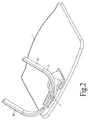
- the bracket ends designated 8a, 8b are no longer parallel to the seat surface 1, but obliquely upward, whereby the placement of a toddler is possible such that the two legs of the infant can be moved laterally on the foot 4 over.
- the pivoting of the foot 4 is characterized achieved that the foot 4 is defined in its lower portion by four surfaces 9a to 9d, which are largely uniformly curved in this lower foot area with respect to the inwardly and outwardly facing surfaces 9a, 9b.
- the adjustment of the foot 4 with respect to the seat plate 1 is to be limited by appropriate measures.
- the foot 4 in the position shown in Figure 1 may have a thickening, whereby the foot 4 can not be moved from the position shown in Fig. 1 in the vertical direction to the seat plate 1 down.
- the end position according to FIG. 2 can be ensured by providing a limit in the form of pins or other stop elements at the foot end of the foot 4.
- the guide 2 in the illustrated embodiment is substantially rectangular in shape and is internally provided with mating surfaces, the guide surfaces for the foot surfaces 9a and 9b being curved in an analogous manner to accommodate the pivoting movement between the position shown in FIGS. 1 and 2 enable.
- the detents for the movement of the foot 4 are not shown in Fig. 1 and Fig. 2.
- the foot 4 at its lower foot portion with a Be provided pivot, which in turn is mounted on or on the seat plate 1, wherein the rotary joint is provided with locking or Dearret ist and in this way also allows pivoting of the base relative to the seat plate 1.
- the foot 4 is not moved relative to the seat plate 1 for adjusting the bracket 8 from the position shown in Fig. 1 in the position shown in Fig. 2 or vice versa, but there is a rotation of the relevant rotary joint over an angular range which can be predetermined by the hinge.
Landscapes
- Health & Medical Sciences (AREA)
- General Health & Medical Sciences (AREA)
- Pediatric Medicine (AREA)
- Buckles (AREA)
- Portable Outdoor Equipment (AREA)
- Organic Low-Molecular-Weight Compounds And Preparation Thereof (AREA)
- Seats For Vehicles (AREA)
Description
- Die Erfindung betrifft einen Kinderhochstuhl mit Durchrutschsicherung, bestehend aus den Kinderhochstuhl tragenden Füßen, die an ihren Oberseiten eine Sitzplatte und eine Sitzlehne aufnehmen.
- Ein Kinderhochstuhl der eingangs genannten Art ist beispielsweise aus der
DE 203 15 348 U1 bekannt. Bei diesem Kinderhochstuhl ist die Durchrutschsicherung in Form eines im Wesentlichen vertikal verlaufenden Sicherungsgurtes vorgesehen, der mit einem Haltebügel in Verbindung steht, wobei der Haltebügel horizontal zwischen Montageplatten höhenverstellbar befestigbar ist. Zwar lässt sich hierbei der Haltebügel grundsätzlich in seiner Höhe verstellen, ein Entfernen des Haltebügels mit Sicherheitsgurt ist jedoch nach einer Festmontage nur aufwendig möglich. - Aus der
DE 299 12 336 U1 ist ein zusammenklappbarer Kinderhochstuhl bekannt, bei dem ein Spieltisch als Durchrutschsicherung vorgesehen ist, der gegenüber einem Fußgestell umklappbar ist, jedoch wegen fehlendem Sicherungsgurt zwischen Spieltisch und Sitzplatte ein Durchrutschen des Kleinkindes nicht ausschließt. - Grundsätzlich besteht das Problem, dass bei Stühlen z. B. nach der
DE 203 15 348 bei fest vorgesehenem Haltebügel mit Sicherungsgurt die Füße des Kleinkindes vor dem Aufsetzen des Kleinkindes auf den Kinderhochstuhl durch die Durchrutschsicherung "hindurchgefädelt" werden müssen, was auch wegen der festmontierten Lehne meist auf Schwierigkeiten stößt und eine Gegenreaktion des Kleinkindes hervorruft oder zu Komplikationen oder Schmerzen führt, wenn die Beine des Kindes nicht richtig entlang der Durchrutschsicherung geführt werden. - Die
US-A-2,669,285 betrifft einen Kinderhochstuhl mit einem Tisch, der an einem Bügel befestigt ist, wobei der Bügel nach unten abstehende Füße trägt, die in zylindrische Rohraufnahmen einzusetzen sind, wobei die zylindrischen Rohraufnahmen an der Sitzplatte vorgesehen sind. Zum Aufstecken ist der Bügel mit Tisch vertikal von oben nach unten in die rohrförmigen Aufnahmen einzustecken und umgekehrt zum Zwecke des Entfernens aus diesen herauszuziehen. Ein Verschwenken des Bügels ist hierbei nicht möglich, solange der Bügel fest an der Sitzplatte angebracht ist. - Aus der
US-A-4,819,988 ist ein Kinderhochstuhl mit einem Tisch bekannt, an welchem eine Strebe befestigt ist, die ihrerseits einen Bügel trägt. Der Bügel ist höhenverstellbar an der Strebe befestigt. Die Strebe kann entweder am Tisch oder am Sitz montiert sein. Der Bügel lässt sich hierbei vertikal verstellen zwischen dem Sitz und dem Tisch. - In der
US-A-2,552,720 ist ein Kinderhochstuhl offenbart mit einem Tablett, das im Wesentlichen mit einer gerade verlaufenden Strebe verbunden ist, die an ihrem unteren Ende durch Arretiermittel auf der Sitzplatte fixiert werden kann. Auf der Sitzplatte sind Öffnungen ausgebildet, um den Tisch in unterschiedlicher Distanz zur Lehne anzuordnen. - Aufgabe vorliegender Erfindung ist es, einen Kinderhochstuhl zu schaffen, der bei vorhandener Durchrutschsicherung auf einfache Weise das Aufsetzen des Kindes in den Kinderhochstuhl ermöglicht.
- Diese Aufgabe wird erfindungsgemäß durch die im Patentanspruch 1 angegebenen Merkmale gelöst.
- Weitere Ausgestaltungen der Erfindung ergeben sich aus dem abhängigen Anspruch 2.
- Bei einer ersten Ausführungsform des erfindungsgemäßen Kinderhochstuhls besteht die Durchrutschsicherung aus einem Fuß und einem Bügel, der als Haltebügel vorzugsweise U-förmig ausgebildet ist. Diese Durchrutschsicherung ist arretierbar an der Sitzplatte befestigt und zum Zwecke des Aufsetzens des Kleinkindes in einer vertikalen Ebene gegenüber der Sitzplatte verschwenkbar.
- Bei einer bevorzugten Ausführungsform ist der Bügel halternde Fuß an seiner Unterseite durch die Sitzplatte hindurch geführt und weist einen umgebogenen Abschnitt auf, so dass bei einem Herausfahren des Standfußes dieser automatisch zusammen mit dem Haltebügel verschwenkt wird infolge einer entsprechenden Krümmung des Fußes an dem durch die Sitzplatte hindurchgehenden Endbereichs.
- Bei einer weiteren Ausführungsform kann der Fuß durch ein arretierbares Gelenk gegenüber der Sitzplatte vorgesehen sein.
- Bei den vorbeschriebenen Ausführungsformen wird somit der Haltebügel aus der normalen die Durchrutschsicherung bildenden Position heraus verschwenkt, bevor das Kleinkind auf den Stuhl gesetzt wird. Anschließend wird in umgekehrter Weise der Haltebügel in die normale Betriebsposition verschwenkt.
- Im Folgenden werden bevorzugte Ausführungsformen des erfindungsgemäßen Kinderhochstuhls anhand der Zeichnung zur Erläuterung weiterer Merkmale beschrieben. Es zeigen:
- Fig. 1 eine erste Ausführungsform eines Teils des Kinderhochstuhls in derjenigen Position, in der ein Durchrutschen verhindert wird;
- Fig. 2 eine Fig. 1 entsprechende Ansicht eines Teils des Kinderhochstuhls in derjenigen Position, in der die Sitzfläche weitgehend frei ist zum Aufsetzen des Kleinkindes;
- Nachfolgend wird eine bevorzugte Ausführungsform des erfindungsgemäßen Kinderhochstuhls beschrieben.
- Fig. 1 zeigt eine perspektivische Teilansicht eines Kinderhochstuhls mit einer Sitzplatte 1, die in bekannter Weise an einem Fußpaar oder zwei Fußpaaren eines Kinderhochstuhls befestigt ist. Die Sitzplatte 1 weist eine Führung 2 auf, welche in die Sitzplatte 1 bzw. in einer in der Sitzplatte 1 ausgebildete Öffnung oder Aussparung 3 integriert eingebaut ist und eine Verstellung des mit 4 bezeichneten Haltefußes in vertikaler Richtung ermöglicht.
- Durch Höhenverstellung des Haltefußes 4 wird bewirkt, dass der Fuß 4 etwa vertikal zur Sitzplatte 1 verschoben wird, wie dies durch den Pfeil 6 veranschaulicht wird. Eine entsprechende Formgebung der Führung 2 bzw. des untern Endes des Fußes 4 bewirkt ein Verschwenken bzw. Umkippen des Fußes 4 relativ zur Sitzplatte 1, in Folge dessen bei einer Bewegung des Fußes 4 aus der Führung 2 heraus der Fuß 4 in einem Winkel zur Sitzplatte 1 derart verschwenkt wird, dass der vom Fuß getragene Bügel 8 die in Fig. 2 gezeigte Position einnimmt. Die Verlagerung des Fußes 4 bewirkt damit bei dieser Variante ein Verschwenken des Bügels 8 über einen vorgegebenen Winkel bei gleichzeitiger weitgehender Freigabe der Sitzfläche (Fig. 2). Auf diese Weise stehen die mit 8a, 8b bezeichneten Bügelenden nicht mehr parallel zur Sitzfläche 1, sondern schräg nach oben, wodurch das Aufsetzen eines Kleinkindes derart möglich ist, dass die beiden Beine des Kleinkindes seitlich an dem Fuß 4 vorbei bewegt werden können. Ersichtlicherweise wird das Verschwenken des Fußes 4 dadurch erreicht, dass der Fuß 4 in seinem unteren Bereich durch vier Flächen 9a bis 9d definiert ist, die in diesem unteren Fußbereich hinsichtlich der nach innen und nach außen weisenden Flächen 9a, 9b weitgehend gleichmäßig gekrümmt sind. Durch das Verschwenken des Fußes 4 zusammen mit dem Bügel 8 wird außerdem die lichte Öffnung zwischen den Bügelenden 8a, 8b einerseits und der Sitzplatte 1 andererseits vergrößert, wodurch sich das leichte Einfädeln der Kinderbeine seitlich an dem Fuß 4 vorbei erreichen lässt.
- Ersichtlicherweise ist die Verstellbewegung des Fußes 4 gegenüber der Sitzplatte 1 durch entsprechende Maßnahmen zu begrenzen. Beispielsweise kann der Fuß 4 in der in Fig.1 gezeigten Position eine Verdickung aufweisen, wodurch der Fuß 4 aus der in Fig. 1 gezeigten Position nicht weiter in vertikaler Richtung zur Sitzplatte 1 nach unten verlagert werden kann. Die Endposition entsprechend Fig. 2 kann dadurch gewährleistet sein, dass am Fußende des Fußes 4 eine Begrenzung in Form von Stiften oder anderer Anschlagelemente vorgesehen ist. Die Führung 2 hat bei der dargestellten Ausführungsform im Wesentlichen rechteckige Gestalt und ist innenseitig mit Gegenführungsflächen versehen, wobei die Führungsflächen für die Fußflächen 9a und 9b in analoger Weise gekrümmt sind, um die Schwenkbewegung zwischen der in Fig. 1 und Fig. 2 gezeigten Position zu ermöglichen. Die Arretierungen für die Bewegung des Fußes 4 sind in Fig. 1 und Fig. 2 nicht dargestellt.
- Anstelle einer Führung 2 der in Fig. 1 und 2 gezeigten Art kann der Fuß 4 an seinem unteren Fußabschnitt mit einem Drehgelenk versehen sein, welches seinerseits an oder auf der Sitzplatte 1 montiert ist, wobei das Drehgelenk mit Arretierung bzw. Dearretierung versehen ist und auf diese Weise gleichfalls eine Verschwenkung des Standfußes gegenüber der Sitzplatte 1 ermöglicht. Bei dieser Ausführungsform wird somit der Fuß 4 zur Verstellung des Bügels 8 aus der in Fig. 1 gezeigten Position in die in Fig. 2 gezeigte Position bzw. umgekehrt nicht gegenüber der Sitzplatte 1 bewegt, sondern es erfolgt eine Drehung des betreffenden Drehgelenks über einen Winkelbereich, der durch das Drehgelenk vorbestimmt sein kann.
Claims (2)
- Kinderhochstuhl mit Durchrutschsicherung, bestehend aus den Kinderhochstuhl tragenden Füßen, die an ihrer Ober-seite eine Sitzplatte (1) und eine Sitzlehne aufnehmen,
wobei die Durchrutschsicherung (4, 8) im Wesentlichen aus einem Bügel (8) und einem Haltefuß (4) besteht,
wobei der Haltefuß (4) an der Sitzplatte (1) angeordnet ist, dadurch gekennzeichnet, dass
die Sitzplatte (1) eine Führungseinrichtung (2) aufweist zur Aufnahme des Haltefußes (4), und gegenüber der dass der Bügel (8) zusammen mit dem Haltefuß (4) gegenüber der Sitzplatte (1) bei in die Führungseinrichtung (2) eingesetztem Haltefuß (4) verschwenkbar vorgesehen ist. - Kinderhochstuhl nach Anspruch 1, dadurch gekennzeichnet, dass der Haltefuß (4) gekrümmte Außenflächen (9a, 9b) aufweist, die mit entsprechend gekrümmten Flächen der Führungseinrichtung (2) in Führungseingriff stehen.
Priority Applications (1)
| Application Number | Priority Date | Filing Date | Title |
|---|---|---|---|
| EP07103026A EP1792552B1 (de) | 2004-07-09 | 2005-06-02 | Kinderhochstuhl |
Applications Claiming Priority (1)
| Application Number | Priority Date | Filing Date | Title |
|---|---|---|---|
| DE102004033333A DE102004033333A1 (de) | 2004-07-09 | 2004-07-09 | Kinderhochstuhl |
Related Child Applications (1)
| Application Number | Title | Priority Date | Filing Date |
|---|---|---|---|
| EP07103026A Division EP1792552B1 (de) | 2004-07-09 | 2005-06-02 | Kinderhochstuhl |
Publications (2)
| Publication Number | Publication Date |
|---|---|
| EP1614371A1 EP1614371A1 (de) | 2006-01-11 |
| EP1614371B1 true EP1614371B1 (de) | 2007-08-15 |
Family
ID=34937181
Family Applications (2)
| Application Number | Title | Priority Date | Filing Date |
|---|---|---|---|
| EP05011937A Expired - Lifetime EP1614371B1 (de) | 2004-07-09 | 2005-06-02 | Kinderhochstuhl |
| EP07103026A Expired - Lifetime EP1792552B1 (de) | 2004-07-09 | 2005-06-02 | Kinderhochstuhl |
Family Applications After (1)
| Application Number | Title | Priority Date | Filing Date |
|---|---|---|---|
| EP07103026A Expired - Lifetime EP1792552B1 (de) | 2004-07-09 | 2005-06-02 | Kinderhochstuhl |
Country Status (3)
| Country | Link |
|---|---|
| EP (2) | EP1614371B1 (de) |
| AT (2) | ATE439067T1 (de) |
| DE (3) | DE102004033333A1 (de) |
Cited By (1)
| Publication number | Priority date | Publication date | Assignee | Title |
|---|---|---|---|---|
| CN103239057A (zh) * | 2012-02-10 | 2013-08-14 | 巧儿宜股份有限公司 | 婴幼儿载具 |
Families Citing this family (7)
| Publication number | Priority date | Publication date | Assignee | Title |
|---|---|---|---|---|
| NO20051629A (no) * | 2005-04-01 | 2006-08-28 | Stokke As | Festebrakett til en stol med to vanger og seteplate |
| WO2008022643A1 (en) * | 2006-08-24 | 2008-02-28 | Leanderform Aps | High chair |
| US8550556B2 (en) | 2010-03-17 | 2013-10-08 | Mattel, Inc. | Reconfigurable infant support structure |
| GB2489442B (en) * | 2011-03-25 | 2013-02-20 | Nuna Int Bv | Child seat having a restraining bar structure and method of operating the same |
| DE102013223128B4 (de) * | 2013-11-13 | 2016-10-20 | Abc Design Gmbh | Kinderhochstuhl |
| CN104706090B (zh) | 2013-12-11 | 2018-01-19 | 明门香港股份有限公司 | 卡合连接机构及儿童座椅组件 |
| US12016469B2 (en) | 2021-08-22 | 2024-06-25 | Skip Hop, Inc. | Convertible child chair |
Family Cites Families (7)
| Publication number | Priority date | Publication date | Assignee | Title |
|---|---|---|---|---|
| US2562629A (en) * | 1947-05-26 | 1951-07-31 | Charles G Miles | Collapsible high chair |
| US2552720A (en) * | 1948-06-18 | 1951-05-15 | Arlington Chair Company | Safety device for high chair trays |
| US2669285A (en) * | 1951-02-28 | 1954-02-16 | Harold S Young | Combination high chair, ladder, and stool |
| US4819988A (en) * | 1987-07-01 | 1989-04-11 | Thomas Hellstrom | Restraining device for a chair |
| US5507550A (en) * | 1994-06-06 | 1996-04-16 | Hasbro, Inc. | Highchair |
| IL117219A0 (en) * | 1996-02-21 | 1996-06-18 | Litaf Ind 1994 Ltd | High chair |
| US5927805A (en) * | 1997-04-18 | 1999-07-27 | Koala Corporation | Stackable children's high-chair |
-
2004
- 2004-07-09 DE DE102004033333A patent/DE102004033333A1/de not_active Ceased
-
2005
- 2005-06-02 DE DE502005007901T patent/DE502005007901D1/de not_active Expired - Lifetime
- 2005-06-02 AT AT07103026T patent/ATE439067T1/de not_active IP Right Cessation
- 2005-06-02 EP EP05011937A patent/EP1614371B1/de not_active Expired - Lifetime
- 2005-06-02 EP EP07103026A patent/EP1792552B1/de not_active Expired - Lifetime
- 2005-06-02 AT AT05011937T patent/ATE369773T1/de active
- 2005-06-02 DE DE502005001217T patent/DE502005001217D1/de not_active Expired - Lifetime
Cited By (1)
| Publication number | Priority date | Publication date | Assignee | Title |
|---|---|---|---|---|
| CN103239057A (zh) * | 2012-02-10 | 2013-08-14 | 巧儿宜股份有限公司 | 婴幼儿载具 |
Also Published As
| Publication number | Publication date |
|---|---|
| DE502005001217D1 (de) | 2007-09-27 |
| EP1792552A1 (de) | 2007-06-06 |
| DE102004033333A1 (de) | 2006-01-26 |
| DE502005007901D1 (de) | 2009-09-24 |
| ATE369773T1 (de) | 2007-09-15 |
| EP1792552B1 (de) | 2009-08-12 |
| ATE439067T1 (de) | 2009-08-15 |
| EP1614371A1 (de) | 2006-01-11 |
Similar Documents
| Publication | Publication Date | Title |
|---|---|---|
| DE69613520T2 (de) | Hochstuhl mit verbessertem Schliessmechanismus | |
| DE2727785C2 (de) | ||
| EP2962602A1 (de) | Stuhl | |
| DE3617623A1 (de) | Stuhl | |
| DE2633044B2 (de) | Höheneinstelleinrichtung für Stahlrückenlehnen | |
| DE29901571U1 (de) | Trainingsgerät, insbesondere Hantelbank | |
| DE102007014995A1 (de) | Sitzteil für einen Kinderhochstuhl | |
| DE4330514C2 (de) | Fahrzeugsitz | |
| DE102014003676A1 (de) | Stuhl, insbesondere Bürostuhl | |
| DE1404660C3 (de) | Verstellsessel | |
| DE69201112T2 (de) | Sitz für Kinderwagen. | |
| EP1614371A1 (de) | Kinderhochstuhl | |
| DE10229436A1 (de) | Kinderstuhl mit einer höhenverstellbaren Sitz- und/oder Fußfläche sowie einem Möbelbeschlag hierfür | |
| DE3249163C2 (de) | ||
| DE102012106817B4 (de) | Verstellmechanismus für eine Rückenlehne | |
| DE3129116A1 (de) | Operationsschemel | |
| EP0336117B1 (de) | Ruderkombinationsgerät | |
| EP0056614A2 (de) | Verstellbarer Kinderstuhl | |
| DE102022205324B4 (de) | Rückenlehnen-Anordnung | |
| DE10119042B4 (de) | Kinderwagen | |
| DE4103313A1 (de) | Hochstuhl | |
| DE19519739A1 (de) | Sitzmöbel mit verstellbarer Rückenlehne | |
| DE202009015647U1 (de) | Sitz zum Befestigen an einer Tischplatte | |
| DE1934876C (de) | Sessel | |
| DE19533069A1 (de) | Stuhl |
Legal Events
| Date | Code | Title | Description |
|---|---|---|---|
| PUAI | Public reference made under article 153(3) epc to a published international application that has entered the european phase |
Free format text: ORIGINAL CODE: 0009012 |
|
| AK | Designated contracting states |
Kind code of ref document: A1 Designated state(s): AT BE BG CH CY CZ DE DK EE ES FI FR GB GR HU IE IS IT LI LT LU MC NL PL PT RO SE SI SK TR |
|
| AX | Request for extension of the european patent |
Extension state: AL BA HR LV MK YU |
|
| 17P | Request for examination filed |
Effective date: 20060607 |
|
| 17Q | First examination report despatched |
Effective date: 20060711 |
|
| AKX | Designation fees paid |
Designated state(s): DE FR |
|
| RBV | Designated contracting states (corrected) |
Designated state(s): AT BE BG CH CY CZ DE DK EE ES FI FR GB GR HU IE IS IT LI LT LU MC NL PL PT RO SE SI SK TR |
|
| 17Q | First examination report despatched |
Effective date: 20060711 |
|
| GRAP | Despatch of communication of intention to grant a patent |
Free format text: ORIGINAL CODE: EPIDOSNIGR1 |
|
| GRAS | Grant fee paid |
Free format text: ORIGINAL CODE: EPIDOSNIGR3 |
|
| GRAA | (expected) grant |
Free format text: ORIGINAL CODE: 0009210 |
|
| AK | Designated contracting states |
Kind code of ref document: B1 Designated state(s): AT BE BG CH CY CZ DE DK EE ES FI FR GB GR HU IE IS IT LI LT LU MC NL PL PT RO SE SI SK TR |
|
| RAP1 | Party data changed (applicant data changed or rights of an application transferred) |
Owner name: HEINRICH GEUTHER KINDERMOEBEL UND -GERAETE GMBH & |
|
| REG | Reference to a national code |
Ref country code: GB Ref legal event code: FG4D Free format text: NOT ENGLISH |
|
| REG | Reference to a national code |
Ref country code: CH Ref legal event code: EP |
|
| REG | Reference to a national code |
Ref country code: IE Ref legal event code: FG4D Free format text: LANGUAGE OF EP DOCUMENT: GERMAN |
|
| REF | Corresponds to: |
Ref document number: 502005001217 Country of ref document: DE Date of ref document: 20070927 Kind code of ref document: P |
|
| ET | Fr: translation filed | ||
| PG25 | Lapsed in a contracting state [announced via postgrant information from national office to epo] |
Ref country code: NL Free format text: LAPSE BECAUSE OF FAILURE TO SUBMIT A TRANSLATION OF THE DESCRIPTION OR TO PAY THE FEE WITHIN THE PRESCRIBED TIME-LIMIT Effective date: 20070815 Ref country code: ES Free format text: LAPSE BECAUSE OF FAILURE TO SUBMIT A TRANSLATION OF THE DESCRIPTION OR TO PAY THE FEE WITHIN THE PRESCRIBED TIME-LIMIT Effective date: 20071126 Ref country code: LT Free format text: LAPSE BECAUSE OF FAILURE TO SUBMIT A TRANSLATION OF THE DESCRIPTION OR TO PAY THE FEE WITHIN THE PRESCRIBED TIME-LIMIT Effective date: 20070815 Ref country code: BG Free format text: LAPSE BECAUSE OF FAILURE TO SUBMIT A TRANSLATION OF THE DESCRIPTION OR TO PAY THE FEE WITHIN THE PRESCRIBED TIME-LIMIT Effective date: 20071115 Ref country code: FI Free format text: LAPSE BECAUSE OF FAILURE TO SUBMIT A TRANSLATION OF THE DESCRIPTION OR TO PAY THE FEE WITHIN THE PRESCRIBED TIME-LIMIT Effective date: 20070815 Ref country code: IS Free format text: LAPSE BECAUSE OF FAILURE TO SUBMIT A TRANSLATION OF THE DESCRIPTION OR TO PAY THE FEE WITHIN THE PRESCRIBED TIME-LIMIT Effective date: 20071215 |
|
| NLV1 | Nl: lapsed or annulled due to failure to fulfill the requirements of art. 29p and 29m of the patents act | ||
| PG25 | Lapsed in a contracting state [announced via postgrant information from national office to epo] |
Ref country code: PL Free format text: LAPSE BECAUSE OF FAILURE TO SUBMIT A TRANSLATION OF THE DESCRIPTION OR TO PAY THE FEE WITHIN THE PRESCRIBED TIME-LIMIT Effective date: 20070815 |
|
| GBV | Gb: ep patent (uk) treated as always having been void in accordance with gb section 77(7)/1977 [no translation filed] |
Effective date: 20070815 |
|
| REG | Reference to a national code |
Ref country code: IE Ref legal event code: FD4D |
|
| PG25 | Lapsed in a contracting state [announced via postgrant information from national office to epo] |
Ref country code: GR Free format text: LAPSE BECAUSE OF FAILURE TO SUBMIT A TRANSLATION OF THE DESCRIPTION OR TO PAY THE FEE WITHIN THE PRESCRIBED TIME-LIMIT Effective date: 20071116 |
|
| PG25 | Lapsed in a contracting state [announced via postgrant information from national office to epo] |
Ref country code: GB Free format text: LAPSE BECAUSE OF FAILURE TO SUBMIT A TRANSLATION OF THE DESCRIPTION OR TO PAY THE FEE WITHIN THE PRESCRIBED TIME-LIMIT Effective date: 20070815 Ref country code: SK Free format text: LAPSE BECAUSE OF FAILURE TO SUBMIT A TRANSLATION OF THE DESCRIPTION OR TO PAY THE FEE WITHIN THE PRESCRIBED TIME-LIMIT Effective date: 20070815 Ref country code: PT Free format text: LAPSE BECAUSE OF FAILURE TO SUBMIT A TRANSLATION OF THE DESCRIPTION OR TO PAY THE FEE WITHIN THE PRESCRIBED TIME-LIMIT Effective date: 20080115 Ref country code: IE Free format text: LAPSE BECAUSE OF FAILURE TO SUBMIT A TRANSLATION OF THE DESCRIPTION OR TO PAY THE FEE WITHIN THE PRESCRIBED TIME-LIMIT Effective date: 20070815 Ref country code: CZ Free format text: LAPSE BECAUSE OF FAILURE TO SUBMIT A TRANSLATION OF THE DESCRIPTION OR TO PAY THE FEE WITHIN THE PRESCRIBED TIME-LIMIT Effective date: 20070815 |
|
| PLBE | No opposition filed within time limit |
Free format text: ORIGINAL CODE: 0009261 |
|
| STAA | Information on the status of an ep patent application or granted ep patent |
Free format text: STATUS: NO OPPOSITION FILED WITHIN TIME LIMIT |
|
| PG25 | Lapsed in a contracting state [announced via postgrant information from national office to epo] |
Ref country code: RO Free format text: LAPSE BECAUSE OF FAILURE TO SUBMIT A TRANSLATION OF THE DESCRIPTION OR TO PAY THE FEE WITHIN THE PRESCRIBED TIME-LIMIT Effective date: 20070815 Ref country code: SE Free format text: LAPSE BECAUSE OF FAILURE TO SUBMIT A TRANSLATION OF THE DESCRIPTION OR TO PAY THE FEE WITHIN THE PRESCRIBED TIME-LIMIT Effective date: 20071115 |
|
| 26N | No opposition filed |
Effective date: 20080516 |
|
| BERE | Be: lapsed |
Owner name: HEINRICH GEUTHER KINDERMOBEL UND -GERATE G.M.B.H. Effective date: 20080630 |
|
| PG25 | Lapsed in a contracting state [announced via postgrant information from national office to epo] |
Ref country code: MC Free format text: LAPSE BECAUSE OF NON-PAYMENT OF DUE FEES Effective date: 20080630 |
|
| PG25 | Lapsed in a contracting state [announced via postgrant information from national office to epo] |
Ref country code: BE Free format text: LAPSE BECAUSE OF NON-PAYMENT OF DUE FEES Effective date: 20080630 |
|
| PG25 | Lapsed in a contracting state [announced via postgrant information from national office to epo] |
Ref country code: EE Free format text: LAPSE BECAUSE OF FAILURE TO SUBMIT A TRANSLATION OF THE DESCRIPTION OR TO PAY THE FEE WITHIN THE PRESCRIBED TIME-LIMIT Effective date: 20070815 |
|
| PG25 | Lapsed in a contracting state [announced via postgrant information from national office to epo] |
Ref country code: SI Free format text: LAPSE BECAUSE OF FAILURE TO SUBMIT A TRANSLATION OF THE DESCRIPTION OR TO PAY THE FEE WITHIN THE PRESCRIBED TIME-LIMIT Effective date: 20070815 |
|
| PG25 | Lapsed in a contracting state [announced via postgrant information from national office to epo] |
Ref country code: CY Free format text: LAPSE BECAUSE OF FAILURE TO SUBMIT A TRANSLATION OF THE DESCRIPTION OR TO PAY THE FEE WITHIN THE PRESCRIBED TIME-LIMIT Effective date: 20070815 |
|
| REG | Reference to a national code |
Ref country code: CH Ref legal event code: PL |
|
| PG25 | Lapsed in a contracting state [announced via postgrant information from national office to epo] |
Ref country code: DK Free format text: LAPSE BECAUSE OF FAILURE TO SUBMIT A TRANSLATION OF THE DESCRIPTION OR TO PAY THE FEE WITHIN THE PRESCRIBED TIME-LIMIT Effective date: 20070815 Ref country code: LI Free format text: LAPSE BECAUSE OF NON-PAYMENT OF DUE FEES Effective date: 20090630 Ref country code: CH Free format text: LAPSE BECAUSE OF NON-PAYMENT OF DUE FEES Effective date: 20090630 |
|
| PG25 | Lapsed in a contracting state [announced via postgrant information from national office to epo] |
Ref country code: HU Free format text: LAPSE BECAUSE OF FAILURE TO SUBMIT A TRANSLATION OF THE DESCRIPTION OR TO PAY THE FEE WITHIN THE PRESCRIBED TIME-LIMIT Effective date: 20080216 Ref country code: LU Free format text: LAPSE BECAUSE OF NON-PAYMENT OF DUE FEES Effective date: 20080602 |
|
| PG25 | Lapsed in a contracting state [announced via postgrant information from national office to epo] |
Ref country code: TR Free format text: LAPSE BECAUSE OF FAILURE TO SUBMIT A TRANSLATION OF THE DESCRIPTION OR TO PAY THE FEE WITHIN THE PRESCRIBED TIME-LIMIT Effective date: 20070815 |
|
| PG25 | Lapsed in a contracting state [announced via postgrant information from national office to epo] |
Ref country code: IT Free format text: LAPSE BECAUSE OF NON-PAYMENT OF DUE FEES Effective date: 20080630 |
|
| PGFP | Annual fee paid to national office [announced via postgrant information from national office to epo] |
Ref country code: AT Payment date: 20120613 Year of fee payment: 8 |
|
| PGFP | Annual fee paid to national office [announced via postgrant information from national office to epo] |
Ref country code: FR Payment date: 20130703 Year of fee payment: 9 |
|
| REG | Reference to a national code |
Ref country code: AT Ref legal event code: MM01 Ref document number: 369773 Country of ref document: AT Kind code of ref document: T Effective date: 20140602 |
|
| REG | Reference to a national code |
Ref country code: FR Ref legal event code: ST Effective date: 20150227 |
|
| PG25 | Lapsed in a contracting state [announced via postgrant information from national office to epo] |
Ref country code: AT Free format text: LAPSE BECAUSE OF NON-PAYMENT OF DUE FEES Effective date: 20140602 Ref country code: FR Free format text: LAPSE BECAUSE OF NON-PAYMENT OF DUE FEES Effective date: 20140630 |
|
| PGFP | Annual fee paid to national office [announced via postgrant information from national office to epo] |
Ref country code: DE Payment date: 20160630 Year of fee payment: 12 |
|
| REG | Reference to a national code |
Ref country code: DE Ref legal event code: R119 Ref document number: 502005001217 Country of ref document: DE |
|
| PG25 | Lapsed in a contracting state [announced via postgrant information from national office to epo] |
Ref country code: DE Free format text: LAPSE BECAUSE OF NON-PAYMENT OF DUE FEES Effective date: 20180103 |