EP1602961B1 - Optical scanning apparatus and image forming apparatus using the same - Google Patents
Optical scanning apparatus and image forming apparatus using the same Download PDFInfo
- Publication number
- EP1602961B1 EP1602961B1 EP05253324A EP05253324A EP1602961B1 EP 1602961 B1 EP1602961 B1 EP 1602961B1 EP 05253324 A EP05253324 A EP 05253324A EP 05253324 A EP05253324 A EP 05253324A EP 1602961 B1 EP1602961 B1 EP 1602961B1
- Authority
- EP
- European Patent Office
- Prior art keywords
- light beam
- optical system
- optical
- main scanning
- light
- Prior art date
- Legal status (The legal status is an assumption and is not a legal conclusion. Google has not performed a legal analysis and makes no representation as to the accuracy of the status listed.)
- Expired - Lifetime
Links
Images


Classifications
-
- G—PHYSICS
- G02—OPTICS
- G02B—OPTICAL ELEMENTS, SYSTEMS OR APPARATUS
- G02B26/00—Optical devices or arrangements for the control of light using movable or deformable optical elements
- G02B26/08—Optical devices or arrangements for the control of light using movable or deformable optical elements for controlling the direction of light
- G02B26/10—Scanning systems
- G02B26/12—Scanning systems using multifaceted mirrors
Definitions
- This invention relates to an optical scanning apparatus and an image forming apparatus using the same, and particularly is suitable for an image forming apparatus such as, for example, a laser beam printer having an electrophotographic process, a digital copying machine or a multifunction printer adapted to record image information by the use of an overfilled optical scanning apparatus.
- an image forming apparatus such as, for example, a laser beam printer having an electrophotographic process, a digital copying machine or a multifunction printer adapted to record image information by the use of an overfilled optical scanning apparatus.
- UFS underfilled optical scanning apparatus
- an image forming apparatus such as a laser beam printer or a digital copying machine
- the higher speed of image recording and higher resolution are required.
- an image output of a high speed and high resolution is required more and more.
- OFS overfilled optical scanning apparatus
- the above-described overfilled optical scanning apparatus is an optical scanning apparatus suitable for high speed and high resolution, but because of the increased number of the deflection surfaces of the polygon mirror thereof, as compared with the underfilled optical scanning apparatus, the angle at which a deflection surface of the polygon mirror can scan becomes narrower, it is necessary to make the focal length of the imaging optical system (scanning lens system) long in order to scan the same scanning width. Therefore, the optical path length of the optical scanning apparatus becomes long, thus posing the problem that the entire apparatus becomes bulky.
- the imaging optical system is constituted by two scanning lenses, and the inverse number of the combined focal length of the two scanning lenses in the deflection surfaces is made smaller than the inverse number of the system focal length of the optical scanning apparatus, thereby achieving a compact overfilled optical scanning apparatus in which the distance from the polygon mirror to the surface to be scanned is short.
- making the inverse number of the combined focal length of the imaging optical system in the deflection surfaces smaller than the inverse number of the system focal length of the optical scanning apparatus can be achieved by converging a light beam incident on the imaging optical system in the main scanning direction.
- the light beam incident on the imaging optical system is set to a convergent light beam (convergent beam) relatively strong in the main scanning direction, and the focal length of the imaging optical system in the main scanning direction is set to the negative. Therefore, when there is a difference ⁇ L in the distances from the rotation center of the polygon mirror to a plurality of deflection surfaces, there is the problem that positional deviation occurs to an imaged spot on the surface to be scanned.
- the above-mentioned positional deviation of the imaged spot on the surface to be scanned occurs without fail in principle if the light beam incident on the imaging optical system is a light beam convergent in a main scanning section, and cannot be avoided.
- Japanese Patent Application Laid-open No. H09-318874 discloses a technique that the optical scanning apparatus can be configured compact by making a light beam incident on the imaging optical system to be a light beam convergent in the main scanning direction, and the positional deviation of the imaged spot on the surface to be scanned can be mitigated by appropriately setting the degree of convergence of the above-mentioned convergent light beam when there is a difference ⁇ L in the distances from the rotation center of the polygon mirror to the plurality of deflection surfaces.
- US 4962982 discusses how to minimise curvature of field in the imaging optical system for apparatus using a convergent light beam.
- an optical scanning apparatus as set out in claim 1, an image forming apparatus as set out in claim 5, an image forming apparatus as set out in claim 6, a colour image forming apparatus as set out in claim 7, a method of making an optical scanning apparatus as set out in claim 9 and a method of making an image forming apparatus as set out in claim 13.
- Optional features are set out in the remaining claims.
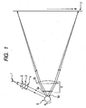
- Fig. 1 is a cross-sectional view (main scanning sectional view) of the essential portions of Embodiment 1 of the optical scanning apparatus of the present invention in a main scanning direction.
- the main scanning direction indicates a direction perpendicular to the rotary axis of deflecting means and the optical axis of a scanning optical element (a direction in which a light beam is reflected and deflected (deflected and scanned) by a light deflector), and a sub-scanning direction indicates a direction parallel to the rotary axis of the light deflector.
- a main scanning section indicates a plane parallel to the main scanning direction and containing the optical axis of an imaging optical system.
- a sub-scanning section indicates a section perpendicular to the main scanning section.
- the reference numeral 1 designates light source unit comprising, for example, a semiconductor laser or the like.
- the reference numeral 2 denotes a light beam conversion element as an optical element, which converts a light beam emitted from the light source unit 1 into a convergent beam.
- the reference numeral 3 designates an aperture stop which limits the light beam emerging from the light beam conversion element 2 and shapes the beam shape thereof.
- the reference numeral 4 denotes an optical system(cylindrical lens) which has predetermined optical power only in the sub-scanning direction, and causes the light beam passed through the aperture stop 3 to be focussed in the sub-scanning section into a substantially linear image on the deflection surface (reflection surface) 5a of a light deflector 5 which will be described later.
- Each of the light beam conversion element 2, the aperture stop 3 and the cylindrical lens 4 constitutes an element of an incidence optical system.
- the reference numeral 5 designates a light deflector which comprises, for example, a polygon mirror of an 8-surface construction (polygon mirror) and is rotated at a constant speed in the direction of arrow A in Fig. 1 by driving means (not shown) such as a motor.
- the reference numeral 6 denotes an imaging optical system (scanning lens system) which has a light condensing function and an f ⁇ characteristic and comprises first and second scanning lenses (f ⁇ lenses) 6a and 6b, and which causes the convergent light beam, which carries information about the image to be formed and which has been reflected and deflected by the light deflector 5, to be imaged on a photosensitive drum surface 7 as a surface to be scanned, and brings the deflection surface 5a of the light deflector 5 and the photosensitive drum surface 7 into conjugate relationship with each other in the sub-scanning section, thereby having an optical face tangle error correction function.
- imaging optical system scanning lens system
- f ⁇ lenses first and second scanning lenses
- the reference numeral 7 designates a photosensitive drum surface as a surface to be scanned.
- a divergent light beam emitted from the semiconductor laser 1 in conformity with information about the image to be formed, is converted into a convergent light beam by the light beam conversion element 2, has its cross-sectional shape limited by the aperture stop 3 and is incident on the cylindrical lens 4.
- the convergent light beam incident on the cylindrical lens 4 emerges therefrom in its intact state in the main scanning section, and is further converged in the sub-scanning section, and is imaged into a focal line shape with its length extending in the main scanning direction near the deflection surface 5a of the polygon mirror 5.
- the beam width in the main scanning section of the light beam at this time is set so as to be sufficiently wider than the facet width of the deflection surface 5a of the polygon mirror (overfilled optical system).
- the convergent light beam reflected and deflected by the deflection surface 5a of the polygon mirror 5 is imaged into a spot shape on the photosensitive drum surface 7 through the first and second scanning lenses 6a and 6b, and the photosensitive drum surface 7 is scanned with the light beam at a uniform speed in the direction of arrow B (main scanning direction) by the polygon mirror 5 being rotated in the direction of arrow A.
- the image is recorded on the photosensitive drum surface 7 as a recording medium.
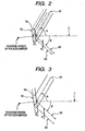
- Fig. 2 is a schematic view of the essential portions around the deflection surface of the polygon mirror in the main scanning section, and shows the deflection surface 5a and the principal ray 61 of the convergent light beam incident on the deflection surface 5a and the principal ray 62 of the light beam reflected and deflected by the deflection surface 5a and travelling toward an imaging optical system (not shown).
- the angle formed by the principal ray 61 of a convergent light beam emerging from the light beam conversion element (not shown) and the optical axis L of the imaging optical system (not shown) is defined as ⁇
- the angle formed by the principal ray 62 of the light beam reflected and deflected by the deflection surface 5a and travelling toward the imaging optical system is defined as ⁇ .
- the principal ray of a light beam reflected and deflected by the deflection surface 5b and reflected at the same angle as the principal ray 62 shifts by h in the main scanning direction as indicated by a ray 63 and is incident on the imaging optical system.
- the width in the main scanning direction of the light beam incident on the polygon mirror 5 is set greater than the width of the deflection surface 5a of the polygon mirror 5 along the rotational direction thereof and therefore, the beam width of the light beam incident on the imaging optical system is determined by the width of the deflection surface 5a.
- the principal ray of the light beam incident on the deflection surface 5b also shifts in the main scanning section.
- Fig. 3 is a schematic view of the essential portions around the deflection surface of the polygon mirror of an underfilled optical scanning apparatus in the main scanning section, and shows the deflection surface 5a and the states of the principal ray 61 of the convergent light beam incident on the deflection surface 5a and the principal ray 62 of the light beam reflected and deflected by the deflection surface 5a and travelling toward the imaging optical system (not shown).
- a point to which attention should be paid here is that the principal ray 63 of the light beam reflected and deflected by the deflection surface 5b and reflected at the same angle as the principal ray 62 shifts in the main scanning direction and is incident on the imaging optical system 6, but the principal ray of the light beam incident on the deflection surface 5b does not shift in the main scanning section.
- the width in the main scanning direction of the light beam incident on the polygon mirror 5 is set smaller than the width along the rotational direction of the deflection surface of the polygon mirror 5 and therefore, the beam width of the light beam incident on the imaging optical system 6 is not determined by the width of the deflection surface.
- Fig. 4 shows, in accordance with the above-mentioned expressions (1) and (2), the relations between the difference ⁇ L in the distances from the rotation center to the deflection surfaces of the polygon mirror and the shift amount h of the light beam incident on the imaging optical system in the overfilled optical scanning apparatus and between the difference ⁇ L in the distances from the rotation center to the deflection surfaces of the polygon mirror and the shift amount h' of the light beam incident on the imaging optical system in the underfilled optical scanning apparatus.
- the overfilled optical scanning apparatus has a smaller shift amount of the light beam caused by the difference ⁇ L in the distances from the rotation center to the respective surfaces of the polygon mirror.
- Fig. 5 describe the phenomenon that positional deviation occurs to an imaged spot on the surface to be scanned if there is a difference ⁇ L in the distances from the rotation center to the plurality of deflection surfaces of the polygon mirror, in the case that the light beam incident on the imaging optical system is a light beam convergent in the main scanning section (convergent light beam).
- Fig. 5 is a cross-sectional view of essential portions for illustrating this phenomenon.
- the reference numeral 6 designates an f ⁇ lens as the imaging optical system, and the distance from the rear side principal plane position of the f ⁇ lens 6 to the natural converging point of the convergent light beam incident on the f ⁇ lens 6 is defined as Sd, the focal length of the f ⁇ lens 6 is defined as f, and the distance from the rear side principal plane position of the f ⁇ lens 6 to a position at which the convergent light beam incident on the f ⁇ lens 6 is converged and imaged by the f ⁇ lens 6 is defined as Sk
- the overfilled optical scanning apparatus has a smaller shift amount ⁇ y of the light beam resulting from the difference ⁇ L in the distances from the rotation center to the deflection surfaces of the polygon mirror in the main scanning section, then in the case that the light beam incident on the f ⁇ lens 6 is convergent in the main scanning direction, the overfilled optical scanning apparatus has a smaller positional deviation of the imaged spot on the surface to be scanned occurring when there is a difference ⁇ L in the distances between the rotation center and the plurality of deflection surfaces of the polygon mirror.
- the overfilled optical scanning apparatus can cause a stronger convergent light beam to be incident than the underfilled optical scanning apparatus, and it becomes possible to further shorten the distance from the polygon mirror to the surface to be scanned.
- the positional deviation amount ⁇ of the imaged spot on the surface to be scanned becomes easy to be visually recognized if it exceeds 1/3 of the main scanning direction pixel interval, which is generally determined from image resolution, and therefore, it is necessary to make the deviation amount ⁇ equal to or smaller than that.
- the following conditional expression is satisfied for all values of ⁇ arising as the light deflector (polygon mirror) rotates: 1 - Sk f ⁇ ⁇ L ⁇ sin ( ⁇ 2 - ⁇ 2 ) + cos ⁇ 2 - ⁇ 2 ⁇ tan ⁇ ⁇ 25.4 3 ⁇ N M , where: f is the focal length of the imaging optical system in the plane containing the optical axis and the main scanning direction; Sk is the distance from the position of the rear side principal plane of the imaging optical system to the imaging point at which the convergent light beam is imaged by the imaging optical system, with respect to focussing in the plane containing the optical axis and the main scanning direction; ⁇ is the angle, in the plane containing the optical axis and the main scanning direction, formed by the optical axis of the imaging optical system and the principal ray of the light beam incident on the light deflector; ⁇ is the angle, in the plane containing the optical
- conditional expression (7) may be set as follows: 1 - Sk f ⁇ ⁇ L ⁇ sin ( ⁇ 2 - ⁇ 2 ) + cos ⁇ 2 - ⁇ 2 ⁇ tan ⁇ ⁇ 25.4 4 ⁇ N M
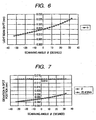
- Fig. 6 is a graph showing the relation between the scanning angle ⁇ and the shift amount h of the light beam in the overfilled optical scanning apparatus of the above-described configuration.
- Embodiment 2 of the present invention will now be described.
- the angle ⁇ formed by the optical axis L of the imaging optical system 6 and the principal ray of the light beam incident on the polygon mirror when the light beam is projected into the main scanning section is set to 0° (it is a front incidence system in which the light beam emitted from the light source unit is incident on the deflection surface of the light deflector from the center of the deflecting angle of the light deflector when projected into the main scanning section), and the light beam is caused to be incident on the deflection surface of the light deflector so as to be incident on the deflection surface at a predetermined angle with respect to a plane orthogonal to the rotary axis of the light deflector, in the sub-scanning section.
- the construction and optical action of the present embodiment are substantially similar to those of Embodiment 1, whereby a similar effect is obtained.
- the aforedescribed angle ⁇ is the value when the light beam has been projected into the main scanning section.
- the angle ⁇ formed in the main scanning section by the optical axis L of the imaging optical system 6 and the principal ray of the light beam incident on the polygon mirror 5 is set to 0°.
- Fig. 8 is a graph showing the relation between the scanning angle ⁇ and the shift amount h of the light beam in the overfilled optical scanning apparatus of the configuration of the present embodiment.
- design is made such that the angle ⁇ formed in the main scanning section by the optical axis L of the imaging optical system 6 and the principal ray of the light beam incident on the polygon mirror 5 is 0°, and therefore, as compared with the aforedescribed Embodiment 1, the shift amount h of the light beam can be made still smaller.
- the overfilled optical scanning apparatus satisfies the above-mentioned conditional expression (7) as a matter of course, and succeeds in more effectively mitigating the positional deviation of the imaged spot on the surface 7 to be scanned.
- the overfilled optical scanning apparatus has the characteristics that the spot diameter in the main scanning direction is somewhat enlarged in a scanning end portion and that the quantity of light is liable to decrease.
- the angle ⁇ formed in the main scanning section by the optical axis L of the imaging optical system 6 and the principal ray of the light beam incident on the polygon mirror 5 becomes 0°, there is also obtained the effect that the above-mentioned enlargement of the spot diameter and the decrease in the quantity of light can be minimized.
- Embodiment 3 of the present invention will now be described.
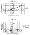
- the angle ⁇ formed by the optical axis L of the imaging optical system 6 and the principal ray of the light beam incident on the polygon mirror 5 when the light beam is projected into the main scanning section is set to 0° (it is a front incidence system in which the light beam emitted from the light source unit is incident on the deflection surface of the deflector from the center of the deflecting angle of the light deflector when projected into the main scanning section), and further the distance Sk from the rear side principal plane of the imaging optical system 6 to the imaging point at which the convergent light beam is imaged by the imaging optical system 6 is set to 135 mm.
- the configuration and optical action of the present embodiment are substantially similar to those of Embodiment 1, whereby a similar effect is obtained.
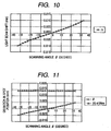
- the angle ⁇ formed in the main scanning section by the optical axis L of the imaging optical system 6 and the principal ray of the light beam incident on the polygon mirror 5 is set to 0°, and further the distance Sk from the rear side principal plane of the imaging optical system 6 to the imaging point at which the convergent light beam is imaged by the imaging optical system 6 is set to 135 mm.
- Fig. 10 is a graph showing the relation between the scanning angle and the shift amount h of the light beam in the overfilled optical scanning apparatus of the configuration of the present embodiment.
- the overfilled optical scanning apparatus As described above, in the present embodiment, there is adopted such a configuration of the overfilled optical scanning apparatus as satisfies the above-mentioned conditional expression (7), whereby it becomes possible to provide a high-performance and compact overfilled optical scanning apparatus which can effectively mitigate the positional deviation of the imaged spot on the surface 7 to be scanned when there is a difference ⁇ L in the distances from the rotation center to the plurality of deflection surfaces of the polygon mirror 5, and can make the degree of the shortening of the optical path length still greater as compared with the case of the underfilled optical scanning apparatus.
- the value (1-Sk/f) in the above-mentioned conditional expression (7) means the degree of convergence of the light beam made incident on the imaging optical system 6, and the greater this value becomes, the stronger the degree of convergence becomes, and it becomes possible to increase the effect of shortening the optical path length.
- the above-mentioned value (1-Sk/f) also affects how much the shift amount h of the light beam is reduced on the surface 7 to be scanned owing to the difference ⁇ L in the distances from the rotation center to the deflection surfaces of the polygon mirror 5.
- the value is set too small, the degree of convergence of the light beam caused to be incident on the imaging optical system 6 will become slight and it will become impossible to obtain the effect of shortening the optical path length.
- each element is set so that the above-mentioned value (1-Sk/f) may satisfy the following conditional expression (8): 0.24 ⁇ 1 - Sk f ⁇ 1.0
- the lower limit value of the conditional expression (8) may be 0.245.
- conditional expression (8) may be set as follows: 0.25 ⁇ 1 - Sk f ⁇ 0.6
- the value (1-Sk/f) is less than the lower limit value of the above-mentioned conditional expression (8), the degree of convergence of the light beam to be incident on the imaging optical system becomes slight and it becomes impossible to obtain the effect of shortening the optical path length, and this is not good. Also, if the value (1-Sk/f) is greater than the upper limit value of the conditional expression (8), the positional deviation of the imaged spot on the surface to be scanned becomes liable to exceed an allowable range, and this is not good.
- the imaging optical system 6 comprises two lenses, this is not restrictive, and the imaging optical system 6 may comprise e.g. a single lens or three or more lenses. Also, the imaging optical system may be constituted by including a diffraction optical element.
- 600 i.e., 600 DPI
- the present invention is not restricted to 600 DPI.
- the positional deviation amount of the spot is within a range of ⁇ 3 ⁇ m.
- the value of "the number of pixels N M per one inch in the main scanning direction on the surface 7 to be scanned determined from the resolution of the image in the main scanning direction” may be 1200 or greater, i.e., 1200 DPI or greater.
- the value of the right side of the conditional expression when the value of N M is 1200 is 0.007055.
- the value of the right side of the conditional expression when the value of N M is 2400 is 0.003528 and therefore, the optical system of Embodiment 2 satisfies the conditional expression even in the case of 2400 DPI.
- the present embodiments can obtain a better effect in an image forming apparatus wherein the resolution is 1200 dpi or greater.
- the effect of the present invention is equally displayed even if the number of light emitting points emitting the light beam of the light source unit is one or plural (two or more light emitting points) and therefore, the present invention is not limited to any particular number of light emitting points emitting the light beam of the light source unit.
- an overfilled optical scanning apparatus in which the optical path length is liable to become long, and a convergent light beam is made incident on an imaging optical system, to thereby achieve a high-performance and compact overfilled optical scanning apparatus which can effectively mitigate the positional deviation of an imaged spot on a surface to be scanned when there is a difference in the distances from the rotation center to the plurality of deflection surfaces of a light deflector, and can make the degree of shortening of an optical path length in comparison with the case of an underfilled optical scanning apparatus still greater,
- An image forming apparatus may use the scanning apparatus.
- the values of such factors as the focal length of the imaging optical system in the main scanning section, the distance from the rear side principal plane position of the imaging optical system to the imaging point at which the convergent light beam is imaged by the imaging optical system, the angle formed by the optical axis of the imaging optical system and the principal ray of the light beam incident on the light deflector, and the angle (scanning angle) formed by the optical axis of the imaging optical system and the light beam reflected and deflected by the light deflector are set to respective optimum conditions in conformity with the difference in the distances from the rotation center to the plurality of deflection surfaces of the light deflector and the resolution in the main scanning direction, to thereby achieve more efficiently a high-performance and compact overfilled optical scanning apparatus and an image forming apparatus using the same.
- Fig. 12 is a cross-sectional view in a sub-scanning direction showing the essential portions of an embodiment of the image forming apparatus.
- the reference numeral 104 designates the image forming apparatus.
- Code data Dc is inputted from an external device 117 such as a personal computer to this image forming apparatus 104.
- This code data Dc is converted into image data (dot data) Di by a printer controller 111 in the image forming apparatus.
- This image data Di is input to an optical scanning unit 100 having the configuration shown in any one of Embodiments 1 to 3.
- a light beam 103 modulated in conformity with the image data Di is emitted from this optical scanning unit 100, and the photosensitive surface of a photosensitive drum 101 is scanned in the main scanning direction by this light beam 103.
- the photosensitive drum 101 which is an electrostatic latent image bearing member (photosensitive member) is clockwisely rotated by a motor 115. With this rotation, the photosensitive surface of the photosensitive drum 101 is moved relative to the light beam 103 in the sub-scanning direction orthogonal to the main scanning direction.
- a charging roller 102 for uniformly charging the surface of the photosensitive drum 101 is provided so as to contact with the surface thereof. The design is made such that the light beam 103 scanned by the aforementioned optical scanning unit 100 is applied to the surface of the photosensitive drum 101 charged by the charging roller 102.
- the light beam 103 is modulated on the basis of the image data Di, and this light beam 103 is applied to the surface of the photosensitive drum 101 to thereby form an electrostatic latent image thereon.
- This electrostatic latent image is developed as a toner image by a developing device 107 disposed further downstream of the applied position of the light beam 103 with respect to the rotational direction of the photosensitive drum 101 so as to abut against the photosensitive drum 101.
- the toner image developed by the developing device 107 is transferred to a sheet 112, which is a material to be transferred, by a transfer roller 108 disposed below the photosensitive drum 101 so as to be opposed to the photosensitive drum 101.
- Sheets 112 are contained in a sheet cassette 109 disposed forwardly (on the right side as viewed in Fig. 12 ) of the photosensitive drum 101, however, they can also be manually fed.
- a sheet feeding roller 110 is disposed on an end portion of the sheet cassette 109 and feeds the sheets 112 in the sheet cassette 109 into a conveying path.
- the sheet 112 to which the unfixed toner image has been transferred in the manner described above is further conveyed to a fixing device disposed rearwardly (on the left side as viewed in Fig. 12 ) of the photosensitive drum 101.
- the fixing device is comprised of a fixing roller 113 having a fixing heater (not shown) therein, and a pressure roller 114 disposed so as to be in pressure contact with this fixing roller 113, and heats the sheet 112 conveyed from the transferring portion while pressuring the sheet 112 by the pressure contact portion between the fixing roller 113 and the pressure roller 114, thereby fix the unfixed toner image on the sheet 112.
- sheet discharging rollers 116 are disposed on the rear side of the fixing roller 113, and discharge the sheet 112 having had the toner image fixed thereon out of the image forming apparatus.
- the printer controller 111 effects not only the conversion of the aforedescribed data, but also the control of various portions in the image forming apparatus including a motor 115, and a motor for the polygon mirror in the optical scanning unit which will be described later.
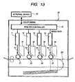
- Fig. 13 is a schematic view of the essential portions of a color image forming apparatus according to an embodiment of the present invention.
- This embodiment is a color image forming apparatus of a tandem type in which four optical scanning apparatuses are arranged side by side and image information is recorded in parallel on the surfaces of photosensitive drums which are image bearing members.
- the reference numeral 60 designates the color image forming apparatus
- the reference numerals 11, 12, 13 and 14 denote optical scanning apparatuses having the construction shown in any one of Embodiments 1 to 3
- the reference numerals 21, 22, 23 and 24 designate photosensitive drums as image bearing members
- the reference numerals 31, 32, 33 and 34 denote developing devices
- the reference numeral 51 designates a conveying belt.
- R (red), G (green) and B (blue) color signals are inputted from an external device 52 such as a personal computer to the color image forming apparatus 60. These color signals are converted into C (cyan), M (magenta), Y (yellow) and B (black) image data (dot data) by a printer controller 53 in the color image forming apparatus. These image data are inputted to the optical scanning apparatuses 11, 12, 13 and 14, respectively. Light beams 41, 42, 43 and 44 modulated in conformity with the respective image data are emitted from these optical scanning apparatuses, and by these light beams, the photosensitive surfaces of the photosensitive drums 21, 22, 23 and 24 are scanned in the main scanning direction.
- the color image forming apparatus is such that the four optical scanning apparatuses (11, 12, 13 and 14) are arranged side by side and respective ones of these correspond to C (cyan), M (magenta), Y (yellow) and B (black) colors, and record image signals (image information) on the surfaces of the photosensitive drums 21, 22, 23 and 24 in parallel to thereby print a color image at a high speed.
- the color image forming apparatus forms latent images of the respective colors on the surfaces of the corresponding photosensitive drums 21, 22, 23 and 24 by the four optical scanning apparatuses 11, 12, 13 and 14 by the use of the light beams based on the respective image data. Thereafter, the images are multiplexly transferred to a recording material to thereby form a sheet of full-color image.
- the external device 52 use may be made, for example, of a color image reading apparatus provided with a CCD sensor.
- a color digital copying machine is constituted by this color image reading apparatus and the color image forming apparatus 60.
Landscapes
- Physics & Mathematics (AREA)
- General Physics & Mathematics (AREA)
- Optics & Photonics (AREA)
- Facsimile Scanning Arrangements (AREA)
- Mechanical Optical Scanning Systems (AREA)
- Laser Beam Printer (AREA)
Applications Claiming Priority (2)
| Application Number | Priority Date | Filing Date | Title |
|---|---|---|---|
| JP2004164645A JP4324019B2 (ja) | 2004-06-02 | 2004-06-02 | 光走査装置及びそれを用いた画像形成装置 |
| JP2004164645 | 2004-06-02 |
Publications (2)
| Publication Number | Publication Date |
|---|---|
| EP1602961A1 EP1602961A1 (en) | 2005-12-07 |
| EP1602961B1 true EP1602961B1 (en) | 2008-10-08 |
Family
ID=34941512
Family Applications (1)
| Application Number | Title | Priority Date | Filing Date |
|---|---|---|---|
| EP05253324A Expired - Lifetime EP1602961B1 (en) | 2004-06-02 | 2005-05-31 | Optical scanning apparatus and image forming apparatus using the same |
Country Status (5)
| Country | Link |
|---|---|
| US (1) | US7304777B2 (enExample) |
| EP (1) | EP1602961B1 (enExample) |
| JP (1) | JP4324019B2 (enExample) |
| DE (1) | DE602005010148D1 (enExample) |
| ES (1) | ES2310799T3 (enExample) |
Families Citing this family (3)
| Publication number | Priority date | Publication date | Assignee | Title |
|---|---|---|---|---|
| EP1701198A1 (en) * | 2005-03-09 | 2006-09-13 | Canon Kabushiki Kaisha | Optical scanning apparatus and image forming apparatus using the same |
| JP4883795B2 (ja) * | 2007-06-28 | 2012-02-22 | キヤノン株式会社 | マルチビーム光走査装置及びそれを用いた画像形成装置 |
| CN113379652B (zh) * | 2021-08-11 | 2021-10-22 | 深圳市先地图像科技有限公司 | 一种激光成像用的线形图像修正方法、系统及相关设备 |
Family Cites Families (21)
| Publication number | Priority date | Publication date | Assignee | Title |
|---|---|---|---|---|
| KR930000718Y1 (ko) * | 1987-01-10 | 1993-02-20 | 미쯔비시 덴끼 가부시끼 가이샤 | 전동식 동력 조향 장치의 토오크 검출기 |
| JPH01224721A (ja) * | 1988-03-04 | 1989-09-07 | Ricoh Co Ltd | 光走査装置 |
| US5539441A (en) * | 1993-11-09 | 1996-07-23 | Xerox Corporation | Jitter reduction in an overfilled raster output polygon scanner system |
| US5781325A (en) * | 1994-12-19 | 1998-07-14 | Fuji Xerox Co., Ltd. | Optical scanning apparatus |
| US5635008A (en) * | 1995-08-07 | 1997-06-03 | Trw Inc. | High precision replication system |
| JP3445092B2 (ja) * | 1996-03-29 | 2003-09-08 | キヤノン株式会社 | 走査光学装置 |
| JP3466863B2 (ja) * | 1996-12-19 | 2003-11-17 | キヤノン株式会社 | 走査光学装置及びそれを用いた画像記録装置 |
| JP3397624B2 (ja) * | 1996-12-19 | 2003-04-21 | キヤノン株式会社 | 走査光学装置及びそれを具備するレーザビームプリンター |
| US6067106A (en) * | 1997-04-16 | 2000-05-23 | Canon Kabushiki Kaisha | Scanning optical apparatus |
| US6317244B1 (en) * | 1998-12-17 | 2001-11-13 | Canon Kabushiki Kaisha | Light-scanning optical system and image-forming apparatus comprising the same |
| US6362470B1 (en) * | 1999-01-26 | 2002-03-26 | Canon Kabushiki Kaisha | Optical scanning apparatus and image forming apparatus and electrophotographic printer using such scanning apparatus |
| JP2000267030A (ja) | 1999-03-16 | 2000-09-29 | Fuji Xerox Co Ltd | 光走査装置 |
| US6256132B1 (en) * | 1999-06-16 | 2001-07-03 | Canon Kabushiki Kaisha | Multi-beam scanning optical system and image forming apparatus using the same |
| JP3667205B2 (ja) * | 1999-07-30 | 2005-07-06 | キヤノン株式会社 | 画像形成装置 |
| JP4497618B2 (ja) * | 2000-02-01 | 2010-07-07 | キヤノン株式会社 | 光走査光学系と光走査装置及びそれを用いた画像形成装置 |
| JP4541523B2 (ja) * | 2000-10-10 | 2010-09-08 | キヤノン株式会社 | マルチビーム光走査光学系及びマルチビーム光走査装置及び画像形成装置 |
| JP2002287057A (ja) * | 2001-03-27 | 2002-10-03 | Canon Inc | マルチビーム走査光学系及びそれを用いた画像形成装置 |
| JP4115104B2 (ja) * | 2001-06-29 | 2008-07-09 | キヤノン株式会社 | マルチビーム走査光学系及びそれを用いた画像形成装置 |
| JP3667286B2 (ja) * | 2002-02-20 | 2005-07-06 | キヤノン株式会社 | 光走査装置及び画像形成装置及びカラー画像形成装置 |
| JP2004302062A (ja) * | 2003-03-31 | 2004-10-28 | Canon Inc | マルチビーム光走査装置 |
| JP4378193B2 (ja) * | 2003-09-04 | 2009-12-02 | キヤノン株式会社 | マルチビーム光走査光学装置及びそれを用いた画像形成装置 |
-
2004
- 2004-06-02 JP JP2004164645A patent/JP4324019B2/ja not_active Expired - Fee Related
-
2005
- 2005-05-31 EP EP05253324A patent/EP1602961B1/en not_active Expired - Lifetime
- 2005-05-31 DE DE602005010148T patent/DE602005010148D1/de not_active Expired - Lifetime
- 2005-05-31 ES ES05253324T patent/ES2310799T3/es not_active Expired - Lifetime
- 2005-06-02 US US11/142,429 patent/US7304777B2/en not_active Expired - Fee Related
Also Published As
| Publication number | Publication date |
|---|---|
| EP1602961A1 (en) | 2005-12-07 |
| DE602005010148D1 (de) | 2008-11-20 |
| JP2005345720A (ja) | 2005-12-15 |
| US7304777B2 (en) | 2007-12-04 |
| ES2310799T3 (es) | 2009-01-16 |
| JP4324019B2 (ja) | 2009-09-02 |
| US20050280696A1 (en) | 2005-12-22 |
Similar Documents
| Publication | Publication Date | Title |
|---|---|---|
| US7884842B2 (en) | Multi-beam scanning apparatus | |
| EP2863252A1 (en) | Optical scanning device and image forming apparatus using the same | |
| US20090244253A1 (en) | Multi-beam optical scanning device | |
| EP1139142B1 (en) | Light-scanning optical system and image-forming apparatus using it | |
| US7050209B2 (en) | Scanning optical apparatus and image forming apparatus using the same | |
| JP4474143B2 (ja) | 光走査装置の被走査面における像面位置の調整方法 | |
| US7391542B2 (en) | Optical scanning apparatus, and image forming apparatus using the same | |
| US7791632B2 (en) | Optical scanning device and image forming apparatus using the same | |
| EP1637916B1 (en) | Optical scanner with aberration correction and image forming apparatus using the same | |
| US7548252B2 (en) | Optical scanning apparatus and color image forming apparatus using the same | |
| US6992807B2 (en) | Optical scanning apparatus and image forming apparatus using the same | |
| EP1602961B1 (en) | Optical scanning apparatus and image forming apparatus using the same | |
| KR100856163B1 (ko) | 광주사장치 및 화상형성장치 | |
| JP2006330581A (ja) | マルチビーム光走査装置及びそれを用いた画像形成装置 | |
| JP2002131664A (ja) | 光走査装置及びそれを用いた画像形成装置 | |
| EP1603321B1 (en) | Multi-beam optical scanning apparatus and image forming apparatus | |
| EP1701198A1 (en) | Optical scanning apparatus and image forming apparatus using the same | |
| JP4769733B2 (ja) | 光走査装置及びそれを用いた画像形成装置 | |
| JP4227404B2 (ja) | 走査光学装置及びそれを用いた画像形成装置 | |
| JP2008310347A (ja) | 走査光学装置及びそれを用いた画像形成装置 | |
| JP2003121773A (ja) | 光走査装置及びそれを用いた画像形成装置 | |
| JP2006285218A (ja) | 光走査装置及びそれを用いた画像形成装置 | |
| JP2003228013A (ja) | マルチビーム光走査光学系及びそれを用いた画像形成装置 |
Legal Events
| Date | Code | Title | Description |
|---|---|---|---|
| PUAI | Public reference made under article 153(3) epc to a published international application that has entered the european phase |
Free format text: ORIGINAL CODE: 0009012 |
|
| AK | Designated contracting states |
Kind code of ref document: A1 Designated state(s): AT BE BG CH CY CZ DE DK EE ES FI FR GB GR HU IE IS IT LI LT LU MC NL PL PT RO SE SI SK TR |
|
| AX | Request for extension of the european patent |
Extension state: AL BA HR LV MK YU |
|
| 17P | Request for examination filed |
Effective date: 20060607 |
|
| AKX | Designation fees paid |
Designated state(s): DE ES FR GB IT NL |
|
| 17Q | First examination report despatched |
Effective date: 20060704 |
|
| GRAP | Despatch of communication of intention to grant a patent |
Free format text: ORIGINAL CODE: EPIDOSNIGR1 |
|
| GRAS | Grant fee paid |
Free format text: ORIGINAL CODE: EPIDOSNIGR3 |
|
| GRAA | (expected) grant |
Free format text: ORIGINAL CODE: 0009210 |
|
| AK | Designated contracting states |
Kind code of ref document: B1 Designated state(s): DE ES FR GB IT NL |
|
| REG | Reference to a national code |
Ref country code: GB Ref legal event code: FG4D |
|
| REF | Corresponds to: |
Ref document number: 602005010148 Country of ref document: DE Date of ref document: 20081120 Kind code of ref document: P |
|
| REG | Reference to a national code |
Ref country code: ES Ref legal event code: FG2A Ref document number: 2310799 Country of ref document: ES Kind code of ref document: T3 |
|
| PLBE | No opposition filed within time limit |
Free format text: ORIGINAL CODE: 0009261 |
|
| STAA | Information on the status of an ep patent application or granted ep patent |
Free format text: STATUS: NO OPPOSITION FILED WITHIN TIME LIMIT |
|
| 26N | No opposition filed |
Effective date: 20090709 |
|
| PGFP | Annual fee paid to national office [announced via postgrant information from national office to epo] |
Ref country code: GB Payment date: 20140523 Year of fee payment: 10 |
|
| PGFP | Annual fee paid to national office [announced via postgrant information from national office to epo] |
Ref country code: IT Payment date: 20140507 Year of fee payment: 10 Ref country code: NL Payment date: 20140430 Year of fee payment: 10 Ref country code: ES Payment date: 20140507 Year of fee payment: 10 Ref country code: DE Payment date: 20140531 Year of fee payment: 10 |
|
| PGFP | Annual fee paid to national office [announced via postgrant information from national office to epo] |
Ref country code: FR Payment date: 20140528 Year of fee payment: 10 |
|
| REG | Reference to a national code |
Ref country code: DE Ref legal event code: R119 Ref document number: 602005010148 Country of ref document: DE |
|
| GBPC | Gb: european patent ceased through non-payment of renewal fee |
Effective date: 20150531 |
|
| PG25 | Lapsed in a contracting state [announced via postgrant information from national office to epo] |
Ref country code: IT Free format text: LAPSE BECAUSE OF NON-PAYMENT OF DUE FEES Effective date: 20150531 |
|
| REG | Reference to a national code |
Ref country code: NL Ref legal event code: MM Effective date: 20150601 |
|
| REG | Reference to a national code |
Ref country code: FR Ref legal event code: ST Effective date: 20160129 |
|
| PG25 | Lapsed in a contracting state [announced via postgrant information from national office to epo] |
Ref country code: GB Free format text: LAPSE BECAUSE OF NON-PAYMENT OF DUE FEES Effective date: 20150531 Ref country code: NL Free format text: LAPSE BECAUSE OF NON-PAYMENT OF DUE FEES Effective date: 20150601 Ref country code: DE Free format text: LAPSE BECAUSE OF NON-PAYMENT OF DUE FEES Effective date: 20151201 |
|
| PG25 | Lapsed in a contracting state [announced via postgrant information from national office to epo] |
Ref country code: FR Free format text: LAPSE BECAUSE OF NON-PAYMENT OF DUE FEES Effective date: 20150601 |
|
| REG | Reference to a national code |
Ref country code: ES Ref legal event code: FD2A Effective date: 20160628 |
|
| PG25 | Lapsed in a contracting state [announced via postgrant information from national office to epo] |
Ref country code: ES Free format text: LAPSE BECAUSE OF NON-PAYMENT OF DUE FEES Effective date: 20150601 |