EP1601115A2 - Vorrichtung für ein Spreizspektrum-Kommunikationssystem - Google Patents
Vorrichtung für ein Spreizspektrum-Kommunikationssystem Download PDFInfo
- Publication number
- EP1601115A2 EP1601115A2 EP20050076778 EP05076778A EP1601115A2 EP 1601115 A2 EP1601115 A2 EP 1601115A2 EP 20050076778 EP20050076778 EP 20050076778 EP 05076778 A EP05076778 A EP 05076778A EP 1601115 A2 EP1601115 A2 EP 1601115A2
- Authority
- EP
- European Patent Office
- Prior art keywords
- signal
- length
- pilot
- pilot signal
- qam
- Prior art date
- Legal status (The legal status is an assumption and is not a legal conclusion. Google has not performed a legal analysis and makes no representation as to the accuracy of the status listed.)
- Granted
Links
Images


Classifications
-
- H—ELECTRICITY
- H04—ELECTRIC COMMUNICATION TECHNIQUE
- H04L—TRANSMISSION OF DIGITAL INFORMATION, e.g. TELEGRAPHIC COMMUNICATION
- H04L27/00—Modulated-carrier systems
- H04L27/0012—Modulated-carrier systems arrangements for identifying the type of modulation
-
- H—ELECTRICITY
- H04—ELECTRIC COMMUNICATION TECHNIQUE
- H04B—TRANSMISSION
- H04B1/00—Details of transmission systems, not covered by a single one of groups H04B3/00 - H04B13/00; Details of transmission systems not characterised by the medium used for transmission
- H04B1/69—Spread spectrum techniques
- H04B1/707—Spread spectrum techniques using direct sequence modulation
- H04B1/7097—Interference-related aspects
-
- H—ELECTRICITY
- H04—ELECTRIC COMMUNICATION TECHNIQUE
- H04L—TRANSMISSION OF DIGITAL INFORMATION, e.g. TELEGRAPHIC COMMUNICATION
- H04L1/00—Arrangements for detecting or preventing errors in the information received
- H04L1/0001—Systems modifying transmission characteristics according to link quality, e.g. power backoff
- H04L1/0006—Systems modifying transmission characteristics according to link quality, e.g. power backoff by adapting the transmission format
-
- H—ELECTRICITY
- H04—ELECTRIC COMMUNICATION TECHNIQUE
- H04L—TRANSMISSION OF DIGITAL INFORMATION, e.g. TELEGRAPHIC COMMUNICATION
- H04L1/00—Arrangements for detecting or preventing errors in the information received
- H04L1/0001—Systems modifying transmission characteristics according to link quality, e.g. power backoff
- H04L1/0009—Systems modifying transmission characteristics according to link quality, e.g. power backoff by adapting the channel coding
-
- H—ELECTRICITY
- H04—ELECTRIC COMMUNICATION TECHNIQUE
- H04L—TRANSMISSION OF DIGITAL INFORMATION, e.g. TELEGRAPHIC COMMUNICATION
- H04L1/00—Arrangements for detecting or preventing errors in the information received
- H04L1/0001—Systems modifying transmission characteristics according to link quality, e.g. power backoff
- H04L1/0036—Systems modifying transmission characteristics according to link quality, e.g. power backoff arrangements specific to the receiver
-
- H—ELECTRICITY
- H04—ELECTRIC COMMUNICATION TECHNIQUE
- H04B—TRANSMISSION
- H04B2201/00—Indexing scheme relating to details of transmission systems not covered by a single group of H04B3/00 - H04B13/00
- H04B2201/69—Orthogonal indexing scheme relating to spread spectrum techniques in general
- H04B2201/707—Orthogonal indexing scheme relating to spread spectrum techniques in general relating to direct sequence modulation
- H04B2201/70701—Orthogonal indexing scheme relating to spread spectrum techniques in general relating to direct sequence modulation featuring pilot assisted reception
-
- H—ELECTRICITY
- H04—ELECTRIC COMMUNICATION TECHNIQUE
- H04B—TRANSMISSION
- H04B2201/00—Indexing scheme relating to details of transmission systems not covered by a single group of H04B3/00 - H04B13/00
- H04B2201/69—Orthogonal indexing scheme relating to spread spectrum techniques in general
- H04B2201/707—Orthogonal indexing scheme relating to spread spectrum techniques in general relating to direct sequence modulation
- H04B2201/70703—Orthogonal indexing scheme relating to spread spectrum techniques in general relating to direct sequence modulation using multiple or variable rates
-
- H—ELECTRICITY
- H04—ELECTRIC COMMUNICATION TECHNIQUE
- H04B—TRANSMISSION
- H04B2201/00—Indexing scheme relating to details of transmission systems not covered by a single group of H04B3/00 - H04B13/00
- H04B2201/69—Orthogonal indexing scheme relating to spread spectrum techniques in general
- H04B2201/707—Orthogonal indexing scheme relating to spread spectrum techniques in general relating to direct sequence modulation
- H04B2201/70707—Efficiency-related aspects
-
- H—ELECTRICITY
- H04—ELECTRIC COMMUNICATION TECHNIQUE
- H04B—TRANSMISSION
- H04B2201/00—Indexing scheme relating to details of transmission systems not covered by a single group of H04B3/00 - H04B13/00
- H04B2201/69—Orthogonal indexing scheme relating to spread spectrum techniques in general
- H04B2201/707—Orthogonal indexing scheme relating to spread spectrum techniques in general relating to direct sequence modulation
- H04B2201/7097—Direct sequence modulation interference
- H04B2201/709709—Methods of preventing interference
-
- H—ELECTRICITY
- H04—ELECTRIC COMMUNICATION TECHNIQUE
- H04L—TRANSMISSION OF DIGITAL INFORMATION, e.g. TELEGRAPHIC COMMUNICATION
- H04L1/00—Arrangements for detecting or preventing errors in the information received
- H04L1/0001—Systems modifying transmission characteristics according to link quality, e.g. power backoff
- H04L1/0002—Systems modifying transmission characteristics according to link quality, e.g. power backoff by adapting the transmission rate
- H04L1/0003—Systems modifying transmission characteristics according to link quality, e.g. power backoff by adapting the transmission rate by switching between different modulation schemes
-
- H—ELECTRICITY
- H04—ELECTRIC COMMUNICATION TECHNIQUE
- H04L—TRANSMISSION OF DIGITAL INFORMATION, e.g. TELEGRAPHIC COMMUNICATION
- H04L1/00—Arrangements for detecting or preventing errors in the information received
- H04L1/0001—Systems modifying transmission characteristics according to link quality, e.g. power backoff
- H04L1/0023—Systems modifying transmission characteristics according to link quality, e.g. power backoff characterised by the signalling
- H04L1/0025—Transmission of mode-switching indication
Definitions
- the present invention relates to a spread spectrum communication system apparatus that controls receiver parameters of A/D conversion speed, a propagation path estimating method and the like.
- An adaptive modulation and coding rate communication system conventionally used changes a cording rate of error correction code and a degree of multi-value modulation according to propagation path quality. Specifically, this system provides high-speed data communication for a user with a good propagation path quality while sacrificing noise-resisting characteristics, and provides low-speed data communication for a user with a poor propagation path quality, attaching importance to noise-resisting characteristics.
- the communication system using such an adaptive modulation is used in radio communication systems such as GSM EDGE, HDR and the like. Also, a similar system is expected to be used additionally in W-CDMA.
- Mode Coding method Modulating method 0 1/2 QPSK 1
- R 1/2 16-QAM 2
- reception quality data indicating quality of received data is transmitted from a receiver to a base station.
- the reception quality data is classified into four grades (modes 0 to 3).
- the mode 0 indicates the lowest quality
- the mode 3 indicates the highest quality.
- the base station selects a coding method and a modulating method as shown in Table 1 on the basis of the mode of the reception quality data.
- Modulating methods include known QPSK, 16-QAM, and 64-QAM.
- the mode 0 indicating the lowest quality
- the mode 3 indicating the highest quality, allows communications transferring a large amount of data.
- reception quality data is transmitted from a receiver to a base station, and the base station selects a combination of an optimum modulating method and coding method on the basis of the reception quality data.
- the receiver is required to maintain good reception characteristics in all combinations of the modulating methods and coding methods handled by the base station.
- FIG. 1 is a graph showing a comparison of effects of shifts in reception timing on the modulating methods. As shown in FIG. 1, 64-QAM is most susceptible to shifts in reception timing.
- FIG. 2 is a graph showing a comparison of effects of errors in synchronous detection on the modulating methods. As shown in FIG. 2, 64-QAM is most susceptible to shifts in reception timing.
- 64-QAM and 16-QAM are susceptible to multipath interference specific to a mobile communication environment. Accordingly, when 64-QAM or 16-QAM is used, it is necessary, for efficient communication, to suppress the interference by using an interference canceller and an equalizer.
- a high-performance receiver compatible with the adaptive modulation and coding rate communication system needs to be designed in accordance with the mode (64-QAM in this case) in which accuracy of each receiving function is most likely to deteriorate due to a shift in reception timing and the like.
- reception processing generally requires an increase in speed of signal processing, and thus increases power consumption.
- a mobile terminal such as a portable telephone, of which low power consumption is required, needs to perform only a minimum function required for reception.
- the present invention relates to a despreading device.
- the despreading device according to the present invention receives a spread signal to be received.
- the despreading device according to the present invention includes receiving means, despreading means, sampling rate supplying means, and control means.
- the receiving means receives a signal to be received that has a control signal specifying a demodulating method.
- the despreading means despreads the received signal on the basis of a sampling rate, and then outputs the control signal.
- the sampling rate supplying means supplies the sampling rate to the despreading means.
- the control means controls the sampling rate on the basis of the control signal.
- the control means controls the sampling rate of the despreading means on the basis of the control signal specifying the demodulating method.
- the sampling rate can be set lower as appropriate according to the demodulating method, and a function (high sampling rate) provided for a demodulating method that is most susceptible to deterioration in accuracy may not be performed at all times.
- the present invention also relates to a propagation path estimating device.
- the propagation path estimating device according to the present invention receives a spread signal to be received.
- the propagation path estimating device according to the present invention includes receiving means, despreading means, propagation path estimating means, and control means.
- the receiving means receives a signal to be received that has a pilot signal and a control signal specifying a demodulating method.
- the despreading means despreads the received signal, and then outputs the pilot signal and the control signal.
- the propagation path estimating means obtains an amount of phase rotation of the received signal on the basis of the pilot signal.
- the control means controls length of the pilot signal used by the propagation path estimating means on the basis of the control signal.
- the control means controls the length of the pilot signal used by the propagation path estimating means on the basis of the control signal specifying the demodulating method.
- the length of the pilot signal used by the propagation path estimating means can be increased as appropriate according to the demodulating method, and a function (a function of reducing the length of the pilot signal used) provided for a demodulating method that is most susceptible to deterioration in accuracy may not be performed at all times.
- the present invention relates to a despreading device.
- the despreading device according to the present invention receives a spread signal to be received.
- the despreading device according to the present invention includes receiving means, despreading means, and control means.
- the receiving means receives a signal to be received that has a pilot signal and a control signal specifying a demodulating method.
- the despreading means despreads the received signal, and then outputs the pilot signal and the control signal.
- the control means controls length of the pilot signal despread by the despreading means on the basis of the control signal.
- the control means controls the length of the pilot signal despread on the basis of the control signal specifying the demodulating method.
- the length of the pilot signal despread can be increased as appropriate according to the demodulating method, and a function (a function of reducing the length of the pilot signal despread) provided for a demodulating method that is most susceptible to deterioration in accuracy may not be performed at all times.
- FIG. 3 is a block diagram showing a configuration of a base station in the adaptive modulation communication system.
- the base station includes a transmitting and receiving device 1101, a despreading unit 1102, a demodulating unit 1103, a reception quality bit extracting unit 1104, a control unit 1105, a control data generating unit 1106, a coding/modulating unit 1107, a spreading unit 1108, an adaptive coding/modulating unit 1109, and a D/A conversion unit 1110.
- the transmitting and receiving device 1101 receives a reception quality data signal transmitted from a user terminal, which will be described later.
- the reception quality data signal indicates quality of a signal received by the user terminal from the base station.
- the reception quality data signal is spread and modulated by the user terminal.
- the transmitting and receiving device 1101 transmits a signal outputted by the D/A conversion unit 1110 to the user terminal.
- the despreading unit 1102 despreads and outputs the reception quality data signal.
- the demodulating unit 1103 demodulates and outputs the output of the despreading unit 1102. Thereby, the reception quality data signal in a state before being spread and modulated is generated.
- the reception quality bit extracting unit 1104 extracts from the reception quality data signal information of the quality of the signal received by the user terminal from the base station (referred to as reception quality data).
- the control unit 1105 determines a coding method for coding and a modulating method for modulating communication data, a control signal, and a pilot signal to be sent to the user terminal.
- the coding method and the modulating method are selected from four combinations shown in Table 2.
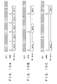
- FIGS. 4A, 4B, and 4C show symbol maps of these modulating methods.
- the QPSK modulation maps coded 2-bit data into one symbol.
- 16-QAM maps 4-bit data into one symbol.
- 64-QAM maps 6-bit data into one symbol.
- an amount of transmissible data is maximum for 64QAM, which maps the maximum number of bits into one symbol, and is minimum for QPSK.
- 64QAM is easily affected by noise because of short distance between adjacent symbols, and QPSK has the most favorable error characteristics at the same noise level.
- control unit 1105 selects a coding/modulating combination allowing transfer of a large amount of data. In a case of a poor propagation path with a high noise (a case of poor reception quality), the control unit 1105 reduces the amount of data transferred, and selects a coding/modulating combination for improving noise resisting characteristics.
- the control data generating unit 1106 generates a control signal for communicating the coding/modulating method selected by the control unit 1105 to the user terminal.
- the coding/modulating unit 1107 subjects an output of the control data generating unit 1106 to coding/modulating processing by a predetermined method.
- the coding/modulating unit 1107 generally performs QPSK modulation.
- the spreading unit 1108 spreads a pilot signal, communication data outputted from the adaptive coding/modulating unit 1109, and the control signal outputted from the coding/modulating unit 1107 by using different spreading codes.
- the adaptive coding/modulating unit 1109 subjects communication data (for example packet data) to coding/modulating processing by the coding method and the modulating method selected by the control unit 1105.
- FIG. 5 shows details of a configuration of the adaptive coding/modulating unit 1109.
- the adaptive coding/modulating unit 1109 has switches 1601 and 1604, coding units 1602a to 1602d, and modulating units 1603a to 1603d.
- the switches 1601 and 1604 are operated to select either one of a plurality of series circuits (1602a-1603a, 1602b-1603b, 1602c-1603c, and 1602d-1603d) formed by the coding units 1602a to 1602d on an input side and the modulating units 1603a to 1603d on an output side according to the coding method and the modulating method selected by the control unit 1105.
- the coding units 1602a to 1602d add error correction code to a signal inputted thereto, that is, code the signal inputted thereto, and then output the coded signal.
- the modulating units 1603a to 1603d subject the signal coded by the coding units 1602a to 1602d to modulation symbol mapping, that is, modulate the signal, and then output the modulated signal.
- the D/A conversion unit 1110 converts a digital signal outputted by the spreading unit 1108 into an analog signal, and then outputs the analog signal to the transmitting and receiving device 1101.
- FIG. 6 shows contents of signals transmitted and received by the base station to and from the user terminal via the transmitting and receiving device 1101.
- the transmitting and receiving device 1101 receives a reception quality data signal 2 sent from the user terminal in an up control channel, and transmits a control signal 4 to the user terminal in a down control channel. As described above, the control signal is determined on the basis of the reception quality data signal 2.
- the transmitting and receiving device 1101 further transmits communication data 6 to the user terminal in a down data channel immediately after transmitting the control signal.
- FIG. 7 is a block diagram showing a configuration of a user terminal (receiving apparatus) according to an embodiment of the present invention.
- the user terminal includes a transmitting and receiving device 101, an A/D conversion unit 111, a despreading unit 102, a control data demodulating and decoding unit 103, a control unit 104, a data demodulating and decoding unit 105, a propagation path estimating unit 106, a reception quality estimating unit 107, a reception quality bit inserting unit 108, a modulating unit 109, a spreading unit 110, a sampling rate supplying unit 112, and an interference suppressing unit 113.
- the transmitting and receiving device 101 receives a signal transmitted from the base station (see FIG. 3).
- the signal received will be referred to as a received signal.
- the received signal has communication data, a pilot signal, and a control signal, and is spread and modulated in the base station.
- the control signal specifies a modulating method, that is, a demodulating method.
- the demodulating method needs to be QPSK. That is, the control signal specifies QPSK as the demodulating method.
- the control signal also specifies a decoding method.
- the transmitting and receiving device 101 transmits a reception quality data signal outputted by the spreading unit 110 to the base station.
- the A/D conversion unit 111 and the despreading unit 102 include despreading means for despreading the received signal and then outputting communication data, a pilot signal, and a control signal.
- the despreading unit 102 may be considered to be the despreading means.
- the transmitting and receiving device 101 and the A/D conversion unit 111 form receiving means.
- the A/D conversion unit 111 converts the received signal into a digital signal.
- the despreading unit 102 despreads the digitized received signal, and then outputs communication data, a pilot signal, and a control signal.
- the interference suppressing unit 113 suppresses multipath interference in an output of the A/D conversion unit 111.
- the suppression of multipath interference specific to a mobile communication environment uses an interference canceller shown in Higuchi et al. "Characteristics of Ultrahigh Speed Packet Transmission Using Multipath Interference Canceller in W-CDMA Downlink” (Technical Report of the Institute of Electronics, Information and Communication Engineers, RCS2000-134, Oct. 2000) or the like, and an equalizer shown in Hooli et al. "Multiple Access Interference Suppression with Linear Chip Equalizers in WCDMA Downlink Receivers", Proc. Global Telecommunications Conf. Pp.467-471. Nov. 1999 or the like.
- the pilot signal output of the despreading unit 102 is inputted to the interference suppressing unit 113, propagation path characteristics are estimated from a pilot component, and then the propagation path characteristics are equalized adaptively.
- the interference suppressing unit 113 Processing by the interference suppressing unit 113 is performed at a sampling rate. The processing therefore requires very high speed arithmetic processing and consumes much power. Hence, it is not desirable for the interference suppressing unit 113 to suppress multipath interference at all times.
- the modulating method is 64-QAM or 16-QAM
- susceptibility to multipath interference is increased as compared with the modulating method of QPSK.
- the control unit 104 reads the demodulating method, and sends the information to the interference suppressing unit 113.
- the demodulating method is 64-QAM or 16-QAM
- the interference suppressing unit 113 suppresses multipath interference
- the demodulating method is QPSK
- the interference suppressing unit 113 does not suppress multipath interference.
- the control data demodulating and decoding unit 103 demodulates and decodes the control signal by a predetermined method. For example, when QPSK modulation of the control signal is predetermined, the control signal is demodulated by the QPSK method.
- the control unit 104 reads the specified demodulating method and decoding method from the control signal outputted from the control data demodulating and decoding unit 103. On the basis of the specified demodulating method, the control unit 104 controls the A/D conversion unit 111, the despreading unit 102, the data demodulating and decoding unit 105, the propagation path estimating unit 106, the sampling rate supplying unit 112, and the interference suppressing unit 113. Details of the control will be described in conjunction with description of the data demodulating and decoding unit 105, the propagation path estimating unit 106, and the sampling rate supplying unit 112. The control of the interference suppressing unit 113 is as described above.
- the data demodulating and decoding unit 105 demodulates and decodes the communication data outputted from the despreading unit 102.
- the demodulating method and the decoding method are specified in the control signal, and sent from the control unit 104.
- the propagation path estimating unit 106 obtains an amount of phase rotation on the basis of the pilot signal outputted from the despreading unit 102. As shown in FIG. 8, the amount of phase rotation is a phase difference between the received signal and an expected received signal. The amount of phase rotation is obtained after averaging M pilot symbols, in consideration of effects of a noise component added on a pilot channel. The number of pilot symbols used, that is, length of the pilot signal used is determined on the basis of the demodulating method specified in the control signal. The demodulating method is sent from the control unit 104.
- the amount of noise added to the pilot symbols varies depending on propagation path characteristics, it is effective to change the length of the pilot signal (number of pilot symbols) according to the propagation path characteristics. Specifically, when there is a large amount of noise, it is desirable to increase the length of the pilot signal used in obtaining an average and thereby reduce effects of the noise. When there is a small amount of noise, it is desirable to decrease the length of the pilot signal used in obtaining an average and thereby obtain data (amount of phase rotation) in as short a time as possible.
- the demodulating method specified in the control signal is QPSK.
- the propagation path estimating unit 106 increases the length of the pilot signal used in obtaining an average.
- the demodulating method specified in the control signal is 64QAM.
- the propagation path estimating unit 106 decreases the length of the pilot signal used in obtaining an average. The thus set length of the pilot signal used in obtaining an average is shown in FIG. 9.
- the length of the pilot signal is shortest (six pilot symbols) in the demodulating method of 64QAM, while the length of the pilot signal is longest (20 pilot symbols) in the demodulating method of QPSK.
- the length of the pilot signal is intermediate (10 pilot symbols) in the demodulating method of 16-QAM.
- the control of the length of the pilot signal has been described supposing that the control unit 104 controls the propagation path estimating unit 106. However, the control unit 104 can also control the length of the pilot signal despread by the despreading unit 102.
- the length of the pilot signal despread in 64QAM is shortest, while the length of the pilot signal despread in the demodulating method of QPSK is longest.
- the length of the pilot signal despread is intermediate in the demodulating method of 16-QAM.
- the reception quality estimating unit 107 estimates a signal-to-noise ratio of the down data channel.
- the signal-to-noise ratio to be estimated is calculated as follows, by obtaining a signal-to-noise ratio of a pilot channel symbol code-multiplexed and transmitted in parallel with the down data channel, and taking into consideration a difference between pilot channel power and data channel power.
- the reception quality bit inserting unit 108 inserts the estimated reception quality value (Data_SNR) into a user terminal transmission signal to be transmitted to the base station by the user terminal and then outputs the result as a reception quality data signal.
- the modulating unit 109 modulates and outputs the reception quality data signal.
- the spreading unit 110 spreads the modulated reception quality data signal, and then outputs the spread reception quality data signal to the transmitting and receiving device 101.
- the sampling rate supplying unit 112 supplies a sampling rate of the despreading unit 102 and the A/D conversion unit 111.
- the sampling rate is determined on the basis of the demodulating method specified in the control signal.
- the demodulating method is sent from the control unit 104.
- the A/D conversion unit 111 converts the analog received signal into a digital signal. For fine synchronous processing in a baseband unit, the A/D conversion is performed by oversampling over a spread chip rate. In processing a wideband received signal such as of W-CDMA, while high-speed A/D conversion is required, it is important, for reduction in power consumption, to select the lowest oversampling rate that can maintain reception characteristics. In W-CDMA using the QPSK modulation, four- or eight-times oversampling is generally appropriate. The 16-QAM modulation requires a higher sampling rate. The 64-QAM modulation requires a still higher sampling rate than the 16-QAM modulation.
- the sampling rate supplying unit 112 supplies a sampling rate four times the chip rate.
- the sampling rate supplying unit 112 supplies a sampling rate eight times the chip rate.
- the sampling rate supplying unit 112 supplies a sampling rate 16 times the chip rate.
- the sampling rate supplying unit 112 supplies the sampling rate 16 times the chip rate only in the case of the 64-QAM modulation. In the cases of the other modulating methods, the sampling rate supplying unit 112 supplies the lower sampling rates.
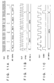
- the sampling rate supplying unit 112 can supply the sampling rate by changing a cycle of a SYNC pulse for data trigger timing, as shown in FIGS. 10A, 10B, and 10C.
- FIG. 10A shows a state of 64QAM data transfer
- FIG. 10B shows a state of 16-QAM transfer
- FIG. 10C shows a state of QPSK transfer.
- the sampling rate supplying unit 112 can supply the sampling rate by changing a data transfer clock speed.
- FIG. 11A shows a state of 64QAM data transfer
- FIG. 11B shows a state of 16-QAM transfer
- FIG. 11C shows a state of QPSK transfer.
- the transmitting and receiving device 101 receives a control signal (S10).
- the received control signal is digitized by the A/D conversion unit 111, despread by the despreading unit 102, and demodulated and decoded by the control data demodulating and decoding unit 103.
- the control signal is set to be subjected to the QPSK modulation in the base station.
- the sampling rate is set to be the minimum value, or four times the chip rate.
- the demodulating method is the QPSK method.
- the length of a pilot signal (number of pilot symbols) used in obtaining an average or the length of the pilot signal despread is set to the maximum length of 20 symbols.
- the control unit 104 reads a specified demodulating method and decoding method from the control signal outputted from the control data demodulating and decoding un.it 103 (S12). Then the control unit 104 determines whether or not communication data is received (S14). When no communication data is received (S14, No), the processing returns to the reception of a control signal (S10). When communication data is received (S14, Yes), the control unit 104 determines the sampling rate of the A/D conversion unit 111 and the like and the length of the pilot signal (number of pilot symbols) used in obtaining an average.
- the control unit 104 controls the sampling rate supplying unit 112 to set the sampling rate to the minimum value, or four times the chip rate. Also, the control unit 104 controls the propagation path estimating unit 106 to set the pilot averaging length to the maximum length of 20 symbols. Incidentally, the control unit 104 may control the despreading unit 102 to set the length (number of pilot symbols) of the pilot signal despread to the maximum length of 20 symbols. The control unit 104 controls the interference suppressing unit 113 to leave suppression of multipath interference stopped
- the demodulating method of QPSK means that processing may be at low speed, and hence that the sampling rate may be low. Since it is expected that much noise is added, however, the pilot averaging length needs to be increased to suppress the noise. Accordingly, the sampling rate is set to the minimum value, and the pilot averaging length is set to the maximum value.
- the demodulating method is QPSK
- susceptibility to multipath interference is less, and therefore the multipath interference interferes less with communications without being suppressed. Thus, the multipath interference is not suppressed, whereby power consumption is reduced.
- the control unit 104 controls the sampling rate supplying unit 112 to set the sampling rate to the intermediate value of eight times the chip rate (S22). Also, the control unit 104 controls the propagation path estimating unit 106 to set the pilot averaging length to the intermediate length of 10 symbols (S24). Incidentally, the control unit 104 may control the despreading unit 102 to set the length (number of pilot symbols) of the pilot signal despread to the intermediate length of 10 symbols. The control unit 104 then controls the interference suppressing unit 113 to suppress multipath interference (S26).
- the demodulating method of 16-QAM means that processing is at medium speed, and hence that a medium sampling rate is required. Since it is expected that a medium level of noise is added, on the other hand, it is desirable that the pilot averaging length be set intermediate for both the suppression of the noise and the instantaneous measurement of an amount of phase rotation. Accordingly, the sampling rate is set to the intermediate value, and the pilot averaging length is set to the intermediate value.
- the demodulating method is 16-QAM, susceptibility to multipath interference is increased, and therefore the multipath interference is suppressed.
- the control unit 104 controls the sampling rate supplying unit 112 to set the sampling rate to the maximum value of 16 times the chip rate (S32). Also, the control unit 104 controls the propagation path estimating unit 106 to set the pilot averaging length to the minimum length of six symbols (S34). Incidentally, the control unit 104 may control the despreading unit 102 to set the length (number of pilot symbols) of the pilot signal despread to the minimum length of six symbols. The control unit 104 then controls the interference suppressing unit 113 to suppress multipath interference (S36).
- the demodulating method of 64QAM means that processing is at high speed, and hence that a high sampling rate is required. Since it is expected that a low level of noise is added, on the other hand, it is desirable that the pilot averaging length be reduced so that the instantaneous measurement of an amount of phase rotation takes precedence over the suppression of the noise. Accordingly, the sampling rate is set to the maximum value, and the pilot averaging length is set to the minimum value.
- the demodulating method is 64QAM, susceptibility to multipath interference is increased, and therefore the multipath interference is suppressed.
- the transmitting and receiving device 101 receives communication data (S40).
- the communication data is digitized by the A/D conversion unit 111, and then despread by the despreading unit 102.
- the despread communication data is supplied to the data demodulating and decoding unit 105 to be demodulated and decoded.
- the demodulating and decoding method is specified by the control signal sent to the data demodulating and decoding unit 105. At this time, an amount of phase rotation estimated by the propagation path estimating unit 106 is included in the control signal and is used for phase correction.
- the pilot signal is sent in conjunction with the communication data, and is sent to the propagation path estimating unit 106 and the reception quality estimating unit 107 via the A/D conversion unit 111 and the despreading unit 102.
- the reception quality estimating unit 107 estimates reception quality.
- the estimated reception quality value is inserted into a user terminal transmission signal by the reception quality bit inserting unit 108, and then the reception quality bit inserting unit 108 outputs a reception quality data signal.
- the reception quality data signal is modulated by the modulating unit 109, spread by the spreading unit 110, and then transmitted to the base station by the transmitting and receiving device 101.
- the control unit 104 sets the sampling rate to four times the chip rate (S42) and sets the pilot averaging length to 20 symbols (S44).
- the control unit 104 stops the suppression of multipath interference by the interference suppressing unit 113 (S46). That is, the control unit 104 initializes the sampling rate, the pilot averaging length, and the state of operation of the interference suppressing unit 113.
- the processing returns to the reception of a control signal (S10). Incidentally, the processing is ended at an arbitrary point in time by turning off power.
- the control unit 104 controls the sampling rate of the despreading means (the A/D conversion unit 111 and the despreading unit 102) on the basis of the control signal specifying the demodulating method (QPSK, 16-QAM, or 64QAM).
- the sampling rate for the demodulating method of QPSK or 16-QAM can be set lower as appropriate than for the demodulating method of 64QAM.
- the sampling rate can be set equal to eight times the chip rate (16-QAM) or four times the chip rate (QPSK).
- a function (setting the sampling rate equal to 16 times the chip rate) provided for the demodulating method (64QAM) that is most susceptible to deterioration in accuracy may not be performed at all times.
- control unit 104 controls the length (pilot averaging length) of the pilot signal used by the propagation path estimating unit 106 on the basis of the control signal specifying the demodulating method (QPSK, 16-QAM, or 64QAM).
- the length of the pilot signal used by the propagation path estimating unit 106 can be increased as appropriate according to the demodulating method.
- the pilot averaging length can be set to 10 symbols (16-QAM) or 20 symbols (QPSK).
- a function (setting the pilot averaging length to six symbols) provided for the demodulating method (64QAM) that is most susceptible to deterioration in accuracy may not be performed at all times.
- control unit 104 controls the length of the despread pilot signal on the basis of the control signal specifying the demodulating method (QPSK, 16-QAM, or 64QAM).
- the length of the despread pilot signal can be increased as appropriate according to the demodulating method.
- the length of the despread pilot signal can be set to 10 symbols (16-QAM) or 20 symbols (QPSK).
- a function (setting the length of the despread pilot signal to six symbols) provided for the demodulating method (64QAM) that is most susceptible to deterioration in accuracy may not be performed at all times.
- control unit 104 controls the state of operation of the interference suppressing unit 113 on the basis of the control signal specifying the demodulating method (QPSK, 16-QAM, or 64QAM).
- the suppression of multipath interference can be controlled according to the demodulating method.
- the suppression of multipath interference can be controlled to be performed (16-QAM and 64QAM) or not to be performed (QPSK).
- a function (performing the suppression of multipath interference) provided for the demodulating method (16-QAM and 64QAM) that is most susceptible to deterioration in accuracy may not be performed at all times.
- the sampling rate, the pilot averaging length, and the state of operation of the interference suppressing unit 113 are determined on the basis of the modulating method (demodulating method) read from the control signal; however, the sampling rate and the like may be determined according to a type of received signal, that is, according to whether there is only a control signal or whether there is also communication data. This provides similar effects. Operation in this case will be described with reference to a flowchart of FIG. 13.
- the reception of a control signal (S10) and the reading of the demodulating method (S12) are the same as in FIG. 12. Then the control unit 104 determines whether or not communication data is received (S14). When no communication data is received (S14, No), the sampling rate and length of a pilot signal used in obtaining an average (referred to as pilot averaging length) are not changed. When communication data is received (S14, Yes), the control unit 104 controls the sampling rate supplying unit 112 to set the sampling rate to the maximum value of 16 times the chip rate (S32). Also, the control unit 104 controls the propagation path estimating unit 106 to set the pilot averaging length to the minimum length of six symbols (S34).
- control unit 104 may control the despreading unit 102 to set the length (number of pilot symbols) of the pilot signal despread to the minimum length of six symbols.
- the control unit 104 then controls the interference suppressing unit 113 to suppress multipath interference.
- a computer including a CPU, a hard disk, a flash memory, and a media (such as floppy disks, CD-ROMs, memory sticks and the like) reading device makes the media reading device read a medium on which a program for realizing the above-described parts is recorded, and then installs the program on the hard disk, in the flash memory or the like.
- the above-described functions can be realized also by such a method.
- a despreading device receiving a spread signal to be received comprising:
- a propagation path estimating device receiving a spread signal to be received comprising:
- a despreading device receiving a spread signal to be received comprising:
- a receiving apparatus for receiving a spread signal to be received comprising:
- a receiving apparatus for receiving a spread signal to be received comprising:
- a receiving apparatus for receiving a spread signal to be received comprising:
- a despreading method for receiving a spread signal to be received comprising:
- a propagation path estimating method for receiving a spread signal to be received comprising:
- a despreading method for receiving a spread signal to be received comprising:
- a receiving method for receiving a spread signal to be received comprising:
- a receiving method for receiving a spread signal to be received comprising:
- a receiving method for receiving a spread signal to be received comprising:
Landscapes
- Engineering & Computer Science (AREA)
- Computer Networks & Wireless Communication (AREA)
- Signal Processing (AREA)
- Quality & Reliability (AREA)
- Digital Transmission Methods That Use Modulated Carrier Waves (AREA)
- Mobile Radio Communication Systems (AREA)
- Detection And Prevention Of Errors In Transmission (AREA)
Applications Claiming Priority (5)
| Application Number | Priority Date | Filing Date | Title |
|---|---|---|---|
| JP2001166808 | 2001-06-01 | ||
| JP2001166808 | 2001-06-01 | ||
| JP2001280117 | 2001-09-14 | ||
| JP2001280117A JP3637884B2 (ja) | 2001-06-01 | 2001-09-14 | 逆拡散装置、伝播路推定装置、受信装置ならびに干渉抑圧装置、逆拡散、伝播路推定、受信および干渉抑圧方法、該プログラムおよび該プログラムを記録した記録媒体 |
| EP02730781A EP1309096B1 (de) | 2001-06-01 | 2002-05-30 | Vorrichtung für ein spreizspektrum-kommunikationssystem |
Related Parent Applications (1)
| Application Number | Title | Priority Date | Filing Date |
|---|---|---|---|
| EP02730781A Division EP1309096B1 (de) | 2001-06-01 | 2002-05-30 | Vorrichtung für ein spreizspektrum-kommunikationssystem |
Publications (3)
| Publication Number | Publication Date |
|---|---|
| EP1601115A2 true EP1601115A2 (de) | 2005-11-30 |
| EP1601115A3 EP1601115A3 (de) | 2006-04-12 |
| EP1601115B1 EP1601115B1 (de) | 2008-09-24 |
Family
ID=26616211
Family Applications (2)
| Application Number | Title | Priority Date | Filing Date |
|---|---|---|---|
| EP20050076778 Expired - Fee Related EP1601115B1 (de) | 2001-06-01 | 2002-05-30 | Vorrichtung für ein Spreizspektrum-Kommunikationssystem |
| EP02730781A Expired - Fee Related EP1309096B1 (de) | 2001-06-01 | 2002-05-30 | Vorrichtung für ein spreizspektrum-kommunikationssystem |
Family Applications After (1)
| Application Number | Title | Priority Date | Filing Date |
|---|---|---|---|
| EP02730781A Expired - Fee Related EP1309096B1 (de) | 2001-06-01 | 2002-05-30 | Vorrichtung für ein spreizspektrum-kommunikationssystem |
Country Status (5)
| Country | Link |
|---|---|
| US (1) | US7283581B2 (de) |
| EP (2) | EP1601115B1 (de) |
| JP (1) | JP3637884B2 (de) |
| DE (2) | DE60214107T2 (de) |
| WO (1) | WO2002099989A1 (de) |
Families Citing this family (18)
| Publication number | Priority date | Publication date | Assignee | Title |
|---|---|---|---|---|
| US7986742B2 (en) | 2002-10-25 | 2011-07-26 | Qualcomm Incorporated | Pilots for MIMO communication system |
| US8320301B2 (en) | 2002-10-25 | 2012-11-27 | Qualcomm Incorporated | MIMO WLAN system |
| US20040081131A1 (en) * | 2002-10-25 | 2004-04-29 | Walton Jay Rod | OFDM communication system with multiple OFDM symbol sizes |
| JP4481684B2 (ja) * | 2003-02-27 | 2010-06-16 | 株式会社エヌ・ティ・ティ・ドコモ | 無線通信システム、無線局及び無線通信方法 |
| US7209716B2 (en) * | 2003-02-27 | 2007-04-24 | Ntt Docomo, Inc. | Radio communication system, radio station, and radio communication method |
| JP3877708B2 (ja) * | 2003-05-23 | 2007-02-07 | 三洋電機株式会社 | 基地局装置、端末装置、通信システム |
| CN1875647B (zh) * | 2003-10-31 | 2011-11-09 | 京瓷株式会社 | 传输速度决定方法和利用该方法的基站装置、终端装置 |
| US9473269B2 (en) | 2003-12-01 | 2016-10-18 | Qualcomm Incorporated | Method and apparatus for providing an efficient control channel structure in a wireless communication system |
| KR100634575B1 (ko) * | 2004-05-12 | 2006-10-16 | 주식회사 케이티프리텔 | 업링크 성능 향상을 위한 적응변조코딩 방법 및 장치 |
| KR100932632B1 (ko) * | 2005-01-24 | 2009-12-21 | 가부시키가이샤 엔티티 도코모 | 이동 통신 단말 및 멀티패스 간섭 제거장치의 기동을 제어하는 방법 |
| JP4551249B2 (ja) | 2005-03-14 | 2010-09-22 | 株式会社エヌ・ティ・ティ・ドコモ | 移動通信端末 |
| JP4129014B2 (ja) * | 2005-08-10 | 2008-07-30 | 株式会社エヌ・ティ・ティ・ドコモ | 移動通信端末 |
| JP4182448B2 (ja) * | 2006-07-27 | 2008-11-19 | ソニー株式会社 | 受信装置、受信方法、プログラム、並びに、記録媒体 |
| EP1901496B1 (de) * | 2006-09-12 | 2010-09-01 | Panasonic Corporation | Verbindungsanpassung in Abhängigkeit von der Kontrollsignalisierung |
| JP4304632B2 (ja) * | 2006-10-12 | 2009-07-29 | ソニー株式会社 | 受信装置、受信方法、プログラム、並びに、記録媒体 |
| US8036240B2 (en) * | 2007-12-14 | 2011-10-11 | Microsoft Corporation | Software defined cognitive radio |
| CN101553052B (zh) * | 2008-04-03 | 2011-03-30 | 华为技术有限公司 | 一种解调方式识别方法和装置 |
| US9124479B2 (en) | 2009-07-15 | 2015-09-01 | Nec Corporation | Wireless base station receiving device, and signal demodulation method and program used therein |
Family Cites Families (13)
| Publication number | Priority date | Publication date | Assignee | Title |
|---|---|---|---|---|
| JP2605615B2 (ja) * | 1993-12-30 | 1997-04-30 | 日本電気株式会社 | スペクトラム拡散受信機 |
| US5544156A (en) * | 1994-04-29 | 1996-08-06 | Telefonaktiebolaget Lm Ericsson | Direct sequence CDMA coherent uplink detector |
| JP3681230B2 (ja) * | 1996-07-30 | 2005-08-10 | 松下電器産業株式会社 | スペクトル拡散通信装置 |
| US5889768A (en) * | 1996-08-30 | 1999-03-30 | Motorola, Inc. | Method of and apparatus for pilot channel acquisition |
| JPH1079720A (ja) * | 1996-09-04 | 1998-03-24 | S Gijutsu Kenkyusho:Kk | スペクトラム拡散伝送用可変変復調回路 |
| WO2000025530A2 (de) * | 1998-10-27 | 2000-05-04 | Siemens Aktiengesellschaft | Verfahren und anordnung zum schätzen von übertragungskanälen in mobilfunksystemen der dritten generation |
| JP3764827B2 (ja) * | 1999-03-01 | 2006-04-12 | 富士通株式会社 | マルチキャリアスペクトル拡散通信における受信機、及び受信方法 |
| JP3428629B2 (ja) * | 1999-03-26 | 2003-07-22 | 日本電気株式会社 | 携帯電話装置及びその電力制御方法 |
| JP2001016135A (ja) * | 1999-06-29 | 2001-01-19 | Nec Corp | 自動周波数制御方法と自動周波数制御方式とcdma受信機 |
| JP3412689B2 (ja) * | 1999-08-26 | 2003-06-03 | 日本電気株式会社 | 携帯電話機 |
| US6839380B1 (en) * | 1999-09-17 | 2005-01-04 | Texas Instruments Incorporated | Robust detection for embedded signaling |
| US6539211B1 (en) * | 2000-01-17 | 2003-03-25 | Qualcomm Incorporated | Efficient system and method for facilitating quick paging channel demodulation via an efficient offline searcher in a wireless communications system |
| US6879623B2 (en) * | 2001-03-28 | 2005-04-12 | Motorola, Inc. | Method and apparatus for timing recovery in a communication device |
-
2001
- 2001-09-14 JP JP2001280117A patent/JP3637884B2/ja not_active Expired - Fee Related
-
2002
- 2002-05-30 DE DE2002614107 patent/DE60214107T2/de not_active Expired - Lifetime
- 2002-05-30 EP EP20050076778 patent/EP1601115B1/de not_active Expired - Fee Related
- 2002-05-30 EP EP02730781A patent/EP1309096B1/de not_active Expired - Fee Related
- 2002-05-30 WO PCT/JP2002/005267 patent/WO2002099989A1/ja active IP Right Grant
- 2002-05-30 DE DE60229075T patent/DE60229075D1/de not_active Expired - Lifetime
- 2002-05-30 US US10/343,466 patent/US7283581B2/en not_active Expired - Fee Related
Non-Patent Citations (2)
| Title |
|---|
| HIGUCHI: "Characteristics of Ultrahigh Speed Packet Transmission Using Multipath Interference Canceller in W-CDMA Downlink", TECHNICAL REPORT OF THE INSTITUTE OF ELECTRONICS, INFORMATION AND COMMUNICATION ENGINEERS, October 2000 (2000-10-01) |
| HOOLI: "Multiple Access Interference Suppression with Linear Chip Equalizers in WCDMA Downlink Receivers", PROC. GLOBAL TELECOMMUNICATIONS CONF., November 1999 (1999-11-01), pages 467 - 471 |
Also Published As
| Publication number | Publication date |
|---|---|
| JP3637884B2 (ja) | 2005-04-13 |
| EP1601115A3 (de) | 2006-04-12 |
| DE60214107D1 (de) | 2006-10-05 |
| DE60214107T2 (de) | 2007-03-08 |
| US7283581B2 (en) | 2007-10-16 |
| WO2002099989A1 (fr) | 2002-12-12 |
| EP1309096B1 (de) | 2006-08-23 |
| EP1309096A1 (de) | 2003-05-07 |
| EP1601115B1 (de) | 2008-09-24 |
| JP2003051764A (ja) | 2003-02-21 |
| DE60229075D1 (de) | 2008-11-06 |
| EP1309096A4 (de) | 2005-03-16 |
| US20040037351A1 (en) | 2004-02-26 |
Similar Documents
| Publication | Publication Date | Title |
|---|---|---|
| US7283581B2 (en) | Spread spectrum communication system apparatus | |
| US8391337B2 (en) | Communication receiver with hybrid equalizer | |
| CN1084092C (zh) | 扩频通信系统中解调和功率控制码元检测的方法 | |
| US6603801B1 (en) | Spread spectrum transceiver for use in wireless local area network and having multipath mitigation | |
| US6977915B2 (en) | Method and system for controlling device transmit power in a wireless communication network | |
| JP3522651B2 (ja) | 通信端末装置及び復調方法 | |
| US20090036155A1 (en) | E-HICH/E-RGCH adaptive threshold setting | |
| JP2000196522A (ja) | 制御信号を発生する装置および方法 | |
| KR20080049686A (ko) | Hsdpa 채널 품질 지시자 선택에서 적응 잡음 내지신호 필터링을 위한 방법 및 장치 | |
| WO2007025712A1 (en) | A method and apparatus for received communication signal processing | |
| US20100284443A1 (en) | Channel Estimation | |
| JP4382672B2 (ja) | 通信信号を復号する方法、装置およびデバイス | |
| US7873324B2 (en) | Apparatus and method for E-HICH/E-RGCH processing, metric estimation and detection | |
| KR100686410B1 (ko) | 이동 통신 시스템에서 트래픽 채널과 파일럿 채널간전력비 검출 장치 및 방법 | |
| US20080037622A1 (en) | Receiving Method And Receiving Apparatus | |
| US7382837B2 (en) | Apparatus and method for estimating a decision boundary in symbol units in a mobile communication system | |
| US8050237B2 (en) | Synchronization channel noise power estimation | |
| JP2004364321A (ja) | 逆拡散装置、伝播路推定装置、受信装置ならびに干渉抑圧装置、逆拡散、伝播路推定、受信および干渉抑圧方法、該プログラムおよび該プログラムを記録した記録媒体 | |
| KR101513562B1 (ko) | 무선통신 시스템에서 레이크 수신기와 등화기를 이용하여 신호를 수신하기 위한 장치 및 방법 | |
| EP1513270B1 (de) | Dopplerspreizungsverfahren in Mobilfunkkommunikationssystemen | |
| US7602836B2 (en) | Receiver | |
| JP3823320B2 (ja) | 逆拡散装置、伝播路推定装置、受信装置ならびに干渉抑圧装置、逆拡散、伝播路推定、受信および干渉抑圧方法、該プログラムおよび該プログラムを記録した記録媒体 | |
| KR100327415B1 (ko) | 씨디엠에이(cdma) 수신장치 및 그에 따른 다이나믹레인지 조절방법 | |
| JP2001257732A (ja) | 移動通信システムのための適応型コヒーレント復調システム | |
| JP3602509B2 (ja) | 復調装置および復調方法 |
Legal Events
| Date | Code | Title | Description |
|---|---|---|---|
| PUAI | Public reference made under article 153(3) epc to a published international application that has entered the european phase |
Free format text: ORIGINAL CODE: 0009012 |
|
| AC | Divisional application: reference to earlier application |
Ref document number: 1309096 Country of ref document: EP Kind code of ref document: P |
|
| AK | Designated contracting states |
Kind code of ref document: A2 Designated state(s): DE FR GB |
|
| AX | Request for extension of the european patent |
Extension state: AL LT LV MK RO SI |
|
| PUAL | Search report despatched |
Free format text: ORIGINAL CODE: 0009013 |
|
| AK | Designated contracting states |
Kind code of ref document: A3 Designated state(s): DE FR GB |
|
| AX | Request for extension of the european patent |
Extension state: AL LT LV MK RO SI |
|
| 17P | Request for examination filed |
Effective date: 20060928 |
|
| 17Q | First examination report despatched |
Effective date: 20061026 |
|
| AKX | Designation fees paid |
Designated state(s): DE FR GB |
|
| GRAP | Despatch of communication of intention to grant a patent |
Free format text: ORIGINAL CODE: EPIDOSNIGR1 |
|
| GRAS | Grant fee paid |
Free format text: ORIGINAL CODE: EPIDOSNIGR3 |
|
| GRAA | (expected) grant |
Free format text: ORIGINAL CODE: 0009210 |
|
| AC | Divisional application: reference to earlier application |
Ref document number: 1309096 Country of ref document: EP Kind code of ref document: P |
|
| AK | Designated contracting states |
Kind code of ref document: B1 Designated state(s): DE FR GB |
|
| REG | Reference to a national code |
Ref country code: GB Ref legal event code: FG4D |
|
| REF | Corresponds to: |
Ref document number: 60229075 Country of ref document: DE Date of ref document: 20081106 Kind code of ref document: P |
|
| PLBE | No opposition filed within time limit |
Free format text: ORIGINAL CODE: 0009261 |
|
| STAA | Information on the status of an ep patent application or granted ep patent |
Free format text: STATUS: NO OPPOSITION FILED WITHIN TIME LIMIT |
|
| 26N | No opposition filed |
Effective date: 20090625 |
|
| REG | Reference to a national code |
Ref country code: GB Ref legal event code: 746 Effective date: 20091130 |
|
| PGFP | Annual fee paid to national office [announced via postgrant information from national office to epo] |
Ref country code: GB Payment date: 20140521 Year of fee payment: 13 |
|
| PGFP | Annual fee paid to national office [announced via postgrant information from national office to epo] |
Ref country code: FR Payment date: 20140527 Year of fee payment: 13 Ref country code: DE Payment date: 20140521 Year of fee payment: 13 |
|
| REG | Reference to a national code |
Ref country code: DE Ref legal event code: R119 Ref document number: 60229075 Country of ref document: DE |
|
| GBPC | Gb: european patent ceased through non-payment of renewal fee |
Effective date: 20150530 |
|
| REG | Reference to a national code |
Ref country code: FR Ref legal event code: ST Effective date: 20160129 |
|
| PG25 | Lapsed in a contracting state [announced via postgrant information from national office to epo] |
Ref country code: DE Free format text: LAPSE BECAUSE OF NON-PAYMENT OF DUE FEES Effective date: 20151201 Ref country code: GB Free format text: LAPSE BECAUSE OF NON-PAYMENT OF DUE FEES Effective date: 20150530 |
|
| PG25 | Lapsed in a contracting state [announced via postgrant information from national office to epo] |
Ref country code: FR Free format text: LAPSE BECAUSE OF NON-PAYMENT OF DUE FEES Effective date: 20150601 |