EP1901496B1 - Verbindungsanpassung in Abhängigkeit von der Kontrollsignalisierung - Google Patents
Verbindungsanpassung in Abhängigkeit von der Kontrollsignalisierung Download PDFInfo
- Publication number
- EP1901496B1 EP1901496B1 EP07011823A EP07011823A EP1901496B1 EP 1901496 B1 EP1901496 B1 EP 1901496B1 EP 07011823 A EP07011823 A EP 07011823A EP 07011823 A EP07011823 A EP 07011823A EP 1901496 B1 EP1901496 B1 EP 1901496B1
- Authority
- EP
- European Patent Office
- Prior art keywords
- control signaling
- link adaptation
- transmitting
- user data
- modulation
- Prior art date
- Legal status (The legal status is an assumption and is not a legal conclusion. Google has not performed a legal analysis and makes no representation as to the accuracy of the status listed.)
- Not-in-force
Links
- 230000011664 signaling Effects 0.000 title claims description 326
- 230000006978 adaptation Effects 0.000 title claims description 188
- 230000001419 dependent effect Effects 0.000 title claims description 22
- 230000005540 biological transmission Effects 0.000 claims description 84
- 230000003595 spectral effect Effects 0.000 claims description 51
- 238000013507 mapping Methods 0.000 claims description 48
- 238000000034 method Methods 0.000 claims description 39
- 238000001514 detection method Methods 0.000 claims description 10
- 230000003044 adaptive effect Effects 0.000 claims description 8
- 238000010295 mobile communication Methods 0.000 claims description 8
- 238000004891 communication Methods 0.000 claims description 7
- 238000012545 processing Methods 0.000 claims description 5
- 238000010397 one-hybrid screening Methods 0.000 claims description 2
- 238000007493 shaping process Methods 0.000 claims description 2
- 230000002776 aggregation Effects 0.000 description 28
- 238000004220 aggregation Methods 0.000 description 28
- 238000013468 resource allocation Methods 0.000 description 16
- 230000008901 benefit Effects 0.000 description 8
- 230000006870 function Effects 0.000 description 7
- 101710116852 Molybdenum cofactor sulfurase 1 Proteins 0.000 description 6
- 230000008569 process Effects 0.000 description 4
- 230000004044 response Effects 0.000 description 4
- 230000008859 change Effects 0.000 description 3
- 230000009467 reduction Effects 0.000 description 3
- 230000003068 static effect Effects 0.000 description 3
- 238000012937 correction Methods 0.000 description 2
- 238000013461 design Methods 0.000 description 2
- 238000005259 measurement Methods 0.000 description 2
- 101001051799 Aedes aegypti Molybdenum cofactor sulfurase 3 Proteins 0.000 description 1
- 101000741965 Homo sapiens Inactive tyrosine-protein kinase PRAG1 Proteins 0.000 description 1
- 102100038659 Inactive tyrosine-protein kinase PRAG1 Human genes 0.000 description 1
- 238000013459 approach Methods 0.000 description 1
- 238000003491 array Methods 0.000 description 1
- 230000009286 beneficial effect Effects 0.000 description 1
- 230000006835 compression Effects 0.000 description 1
- 238000007906 compression Methods 0.000 description 1
- 230000000694 effects Effects 0.000 description 1
- 238000011156 evaluation Methods 0.000 description 1
- 238000005562 fading Methods 0.000 description 1
- 230000006872 improvement Effects 0.000 description 1
- 230000007774 longterm Effects 0.000 description 1
- 230000007246 mechanism Effects 0.000 description 1
- 238000012986 modification Methods 0.000 description 1
- 230000004048 modification Effects 0.000 description 1
- 230000011218 segmentation Effects 0.000 description 1
- 208000037918 transfusion-transmitted disease Diseases 0.000 description 1
Images


Classifications
-
- H—ELECTRICITY
- H04—ELECTRIC COMMUNICATION TECHNIQUE
- H04L—TRANSMISSION OF DIGITAL INFORMATION, e.g. TELEGRAPHIC COMMUNICATION
- H04L1/00—Arrangements for detecting or preventing errors in the information received
- H04L1/0001—Systems modifying transmission characteristics according to link quality, e.g. power backoff
- H04L1/0023—Systems modifying transmission characteristics according to link quality, e.g. power backoff characterised by the signalling
- H04L1/0025—Transmission of mode-switching indication
-
- H—ELECTRICITY
- H04—ELECTRIC COMMUNICATION TECHNIQUE
- H04L—TRANSMISSION OF DIGITAL INFORMATION, e.g. TELEGRAPHIC COMMUNICATION
- H04L1/00—Arrangements for detecting or preventing errors in the information received
- H04L1/0001—Systems modifying transmission characteristics according to link quality, e.g. power backoff
- H04L1/0002—Systems modifying transmission characteristics according to link quality, e.g. power backoff by adapting the transmission rate
- H04L1/0003—Systems modifying transmission characteristics according to link quality, e.g. power backoff by adapting the transmission rate by switching between different modulation schemes
- H04L1/0004—Systems modifying transmission characteristics according to link quality, e.g. power backoff by adapting the transmission rate by switching between different modulation schemes applied to control information
-
- H—ELECTRICITY
- H04—ELECTRIC COMMUNICATION TECHNIQUE
- H04L—TRANSMISSION OF DIGITAL INFORMATION, e.g. TELEGRAPHIC COMMUNICATION
- H04L1/00—Arrangements for detecting or preventing errors in the information received
- H04L1/0001—Systems modifying transmission characteristics according to link quality, e.g. power backoff
- H04L1/0002—Systems modifying transmission characteristics according to link quality, e.g. power backoff by adapting the transmission rate
- H04L1/0003—Systems modifying transmission characteristics according to link quality, e.g. power backoff by adapting the transmission rate by switching between different modulation schemes
- H04L1/0005—Systems modifying transmission characteristics according to link quality, e.g. power backoff by adapting the transmission rate by switching between different modulation schemes applied to payload information
-
- H—ELECTRICITY
- H04—ELECTRIC COMMUNICATION TECHNIQUE
- H04L—TRANSMISSION OF DIGITAL INFORMATION, e.g. TELEGRAPHIC COMMUNICATION
- H04L1/00—Arrangements for detecting or preventing errors in the information received
- H04L1/0001—Systems modifying transmission characteristics according to link quality, e.g. power backoff
- H04L1/0015—Systems modifying transmission characteristics according to link quality, e.g. power backoff characterised by the adaptation strategy
- H04L1/0016—Systems modifying transmission characteristics according to link quality, e.g. power backoff characterised by the adaptation strategy involving special memory structures, e.g. look-up tables
-
- H—ELECTRICITY
- H04—ELECTRIC COMMUNICATION TECHNIQUE
- H04L—TRANSMISSION OF DIGITAL INFORMATION, e.g. TELEGRAPHIC COMMUNICATION
- H04L1/00—Arrangements for detecting or preventing errors in the information received
- H04L1/0001—Systems modifying transmission characteristics according to link quality, e.g. power backoff
- H04L1/0023—Systems modifying transmission characteristics according to link quality, e.g. power backoff characterised by the signalling
- H04L1/0028—Formatting
- H04L1/0029—Reduction of the amount of signalling, e.g. retention of useful signalling or differential signalling
-
- H—ELECTRICITY
- H04—ELECTRIC COMMUNICATION TECHNIQUE
- H04L—TRANSMISSION OF DIGITAL INFORMATION, e.g. TELEGRAPHIC COMMUNICATION
- H04L1/00—Arrangements for detecting or preventing errors in the information received
- H04L1/0001—Systems modifying transmission characteristics according to link quality, e.g. power backoff
- H04L1/0036—Systems modifying transmission characteristics according to link quality, e.g. power backoff arrangements specific to the receiver
- H04L1/0038—Blind format detection
-
- H—ELECTRICITY
- H04—ELECTRIC COMMUNICATION TECHNIQUE
- H04W—WIRELESS COMMUNICATION NETWORKS
- H04W72/00—Local resource management
- H04W72/20—Control channels or signalling for resource management
- H04W72/23—Control channels or signalling for resource management in the downlink direction of a wireless link, i.e. towards a terminal
-
- H—ELECTRICITY
- H04—ELECTRIC COMMUNICATION TECHNIQUE
- H04W—WIRELESS COMMUNICATION NETWORKS
- H04W8/00—Network data management
- H04W8/02—Processing of mobility data, e.g. registration information at HLR [Home Location Register] or VLR [Visitor Location Register]; Transfer of mobility data, e.g. between HLR, VLR or external networks
- H04W8/04—Registration at HLR or HSS [Home Subscriber Server]
-
- H—ELECTRICITY
- H04—ELECTRIC COMMUNICATION TECHNIQUE
- H04L—TRANSMISSION OF DIGITAL INFORMATION, e.g. TELEGRAPHIC COMMUNICATION
- H04L1/00—Arrangements for detecting or preventing errors in the information received
- H04L1/12—Arrangements for detecting or preventing errors in the information received by using return channel
- H04L1/16—Arrangements for detecting or preventing errors in the information received by using return channel in which the return channel carries supervisory signals, e.g. repetition request signals
- H04L1/1607—Details of the supervisory signal
- H04L1/1671—Details of the supervisory signal the supervisory signal being transmitted together with control information
-
- H—ELECTRICITY
- H04—ELECTRIC COMMUNICATION TECHNIQUE
- H04L—TRANSMISSION OF DIGITAL INFORMATION, e.g. TELEGRAPHIC COMMUNICATION
- H04L5/00—Arrangements affording multiple use of the transmission path
- H04L5/0001—Arrangements for dividing the transmission path
- H04L5/0003—Two-dimensional division
- H04L5/0005—Time-frequency
- H04L5/0007—Time-frequency the frequencies being orthogonal, e.g. OFDM(A), DMT
Definitions
- the invention relates to a method and apparatus for providing an improved scheme for encoding control information for transmitting user data.
- a shared data channel may for example have one of the following configurations:
- Fig. 1 shows a packet-scheduling system on a shared channel for systems with a single shared data channel.
- a sub-frame also referred to as a time slot
- the scheduler e.g. the Physical Layer or MAC Layer Scheduler
- DRA dynamic resource allocation
- a TTI transmission time interval
- a TTI may also span over multiple sub-frames.
- the smallest unit of radio resources (also referred to as a resource block or resource unit), which can be allocated in OFDM systems, is typically defined by one sub-frame in time domain and by one subcarrier/subband in the frequency domain.
- this smallest unit of radio resources is defined by a sub-frame in the time domain and a code in the code domain.
- this smallest unit is defined by one sub-frame in time domain, by one subcarrier/subband in the frequency domain and one code in the code domain. Note that dynamic resource allocation may be performed in time domain and in code/frequency domain.
- TDS time domain scheduling
- dynamic user rate adaptation The main benefits of packet-scheduling are the multi-user diversity gain by time domain scheduling (TDS) and dynamic user rate adaptation.
- the scheduler can assign available resources (codes in case of CDMA, subcarriers/subbands in case of OFDMA) to users having good channel conditions in time domain scheduling.
- Time Domain Scheduling TDS
- Frequency Domain Scheduling FDS
- TDS Time Domain Scheduling
- FDS Frequency Domain Scheduling
- the OFDM signal is in frequency domain constructed out of multiple narrowband subcarriers (typically grouped into subbands), which can be assigned dynamically to different users.
- the frequency selective channel properties due to multi-path propagation can be exploited to schedule users on frequencies (subcarriers/subbands) on which they have a good channel quality (multi-user diversity in frequency domain).
- the bandwidth is divided into multiple subbands, which consist out of multiple subcarriers.
- the smallest unit on which a user may be allocated would have a bandwidth of one subband and a duration of one sub-frame (which may correspond to one or multiple OFDM symbols), which is denoted as a resource block (RB).
- RB resource block
- a subband consists of consecutive subcarriers.
- a scheduler may also allocate a user over multiple consecutive or non-consecutive subbands and/or sub-frames.
- a 10 MHz system may consist out of 600 subcarriers with a subcarrier spacing of 15 kHz.
- the 600 subcarriers may then be grouped into 24 subbands (a 25 subcarriers), each subband occupying a bandwidth of 375 kHz.
- a resource block RB would span over 375 kHz and 0.5 ms according to this example.
- the data for a given user should be allocated on resource blocks on which the users have a good channel condition.
- resource blocks are close to each other and therefore, this transmission mode is in also denoted as localized mode (LM).
- LM localized mode
- FIG. 2 An example for a localized mode channel structure is shown in Fig. 2 .
- neighboring resource blocks are assigned to four mobile stations (MS1 to MS4) in the time domain and frequency domain.
- Each resource block consists of a portion for carrying Layer 1 and/or Layer 2 control signaling and a portion carrying the user data for the mobile stations.
- the users may be allocated in a distributed mode (DM) as shown in Fig. 3 .
- DM distributed mode
- a user mobile station
- resource blocks which are distributed over a range of resource blocks.
- distributed mode a number of different implementation options are possible.
- a pair of users (MSs1/2 and MSs 3/4) share the same resource blocks.
- 3GPP RAN WG#1 Tdoc R1-062089 "Comparison between RB-level and Sub-carrier-level Distributed Transmission for Shared Data Channel in E-UTRA Downlink", August 2006 (available at http://www.3gpp.org)
- RBs resources allocated to localized mode and distributed mode
- the amount of resources (RBs) allocated to localized mode and distributed mode may be fixed, semi-static (constant for tens/hundreds of sub-frames) or even dynamic (different from sub-frame to sub-frame).
- one or multiple data blocks may be allocated separately to the same user (mobile station) on different resource blocks, which may or may not belong to the same service or Automatic Repeat reQuest (ARQ) process. Logically, this can be understood as allocating different users.
- link adaptation is a typical measure to exploit the benefits resulting from dynamic resource allocation.
- AMC Adaptive Modulation and Coding
- MCS modulation and coding scheme
- MCS modulation and coding scheme
- HARQ hybrid ARQ
- Layer 1/Layer 2 (L1/L2) control signaling is transmitted on the downlink (e.g. together with the user data).
- L1/L2 Layer 1/Layer 2
- the information sent on the L1/L2 control signaling may be separated into the following two categories.
- DCI Dedicated Control Information carrying Cat. 2/3 as for example specified in the above mentioned 3GPP TR 25.814 (see page 29, Table 7.1.1.2.3.1-1
- Downlink scheduling information required by a UE :
- the following table is intended to exemplarily illustrate how the encoded L1/L2 control signaling information may be mapped to modulation scheme and coding rate (or payload size): Table 2 MCS Modulation Scheme Indicator Modulation Scheme Payload Size Indicator Code Rate Payload (One RB allocated) Payload ( M RBs allocated) 1 00 QPSK 00 0.2 50 M x 50 2 00 QPSK 01 0.4 100 M x 100 3 00 QPSK 10 0.6 150 M x 150 4 00 QPSK 11 0.8 200 M x 200 5 01 16-QAM 00 0.5 250 M x 250 6 01 16-QAM 01 0.6 300 M x 300 7 01 16-QAM 10 0.7 350 M x 350 8 01 16-QAM 11 0.8 400 M x 400 9 10 64-QAM 00 0.6 450 M x 450 10 10 64-QAM 01 0.7 525 M x 525 11 10 64-QAM 10 0.8 600 M x 600 12 10 64-QAM 11 0.9 675 M x
- the table shows the possible bit patterns (marked in bold letters) that indicate modulation scheme (Modulation Scheme Indicator) and payload size (Payload Size Indicator).
- the bit pattern "0000” thus represents the modulation and coding scheme having the lowest spectral efficiency and rate, while the bit pattern "1011” indicates the modulation and coding scheme having the highest spectral efficiency and rate.
- L1/L2 control signaling information may be included in each sub-frame, an efficient coding of the L1/L2 control signaling is desirable in order to reduce the control signaling overhead.
- WO 2004/068886 A1 discloses a concept for HSUPA (uplink data transmission), where the base station signals a range of transport formats for data transmission from which a mobile station should select from for data transmission with the transport format range being dependent on the channel quality. This control signaling of the range of transport formats for data transmission is not subject to link adaptation.
- US 2003/092461 A1 discloses a radio communication system comprising a primary station (100) and a secondary station.
- the primary station is able to employ one of a plurality of transmission schemes for transmissions to the secondary station.
- the secondary station determines a quality parameter relating to a downlink channel and determines from this parameter a measurement report that is signaled to the primary station.
- the measurement report indicates a suitable transmission power for one transmission scheme, and the primary station is able to determine from a plurality of power offsets between transmission schemes respective transmission powers for a plurality of transmission schemes.
- the power offsets may be signaled to the primary station by the secondary station.
- Such a scheme provides sufficient flexibility to handle a wide range of receiver capabilities without the need for excessive signaling.
- US 2006/018347 discloses a shared signaling channel that has multiple segments, and parameters for this channel that may or may not be sent to users in advance. For example, the number of segments, the size and rate of each segment, and so on may be broadcast to the users via an overhead channel.
- the transmit power for each segment is not broadcast to the users and can range from zero to the total transmit power.
- a base station obtains signaling for all terminals within its coverage and maps the signaling for each terminal to at least one segment used for the terminal, which may be dynamically selected.
- the base station processes (e.g., jointly or individually encodes) the signaling mapped to each segment and generates output data for the segment.
- the output data for each segment is multiplexed onto the system resources allocated for the segment and transmitted at the selected power level.
- a main object of the invention is to suggest an improved scheme for encoding control information related to the transmission of user data.
- a further object is to reduce the control signaling overhead.
- One main aspect of the invention is to interpret information on link adaptation for transmitting the user data comprised in control signaling depending on at least one link adaptation parameter employed for transmitting the control signaling. Another aspect is to interpret information on the resource allocation for transmitting the user data comprised in control signaling depending on at least one link adaptation parameter employed for transmitting the control signaling or alternatively, if the control signaling is mapped on so-called Control Channel Elements, depending on the Control Channel Element indices to which the control signaling is mapped.
- a method in which information on at least one link adaptation parameter for transmitting the user data is interpreted e.g. to determine the at least one link adaptation parameter for transmitting the user data.
- the at least one link adaptation parameter for transmitting the user data is comprised in control signaling and the interpretation of the information depends on at least one link adaptation parameter employed for transmitting the control signaling.
- a receiving entity may receive the control signaling, and may determine the at least one link adaptation parameter for transmitting the user data from the control signaling as described above. Next, the receiving entity may receive the user data using the determined at least one link adaptation parameter for transmitting the user data. Alternatively, the receiving entity may also transmit the user data using the determined at least one link adaptation parameter for transmitting the user data.
- control data may be received that comprises link adaptation information defining the at least one link adaptation parameter employed for transmitting the control signaling.
- the transmission of control signaling is also subject to link adaptation so that it may be advantageous to signal the used link adaptation for the control signaling to a receiving entity by means of another control data (e.g. broadcasted on a broadcast channel or configured by higher layers).
- the link adaptation parameters used for the control signaling may depend in the resources on which the control signaling is mapped in order to reduce the control data on the broadcast channel. For example, these resources can be configured in a semi-static way.
- blind detection of the control signaling is used by a receiving entity by blindly detecting the link adaptation parameters used for the control signaling.
- This may have the advantage that no additional control data may need to be signaled and thus no additional overhead for indicating the link adaptation used for the control signaling is necessary.
- Blind detection may for example be advantageous, if the number of possible link adaptations is limited to a predetermined number so that the reception of the control signaling utilizing blind detection does not imply an unacceptable burden in terms of processing capability and power usage for a mobile receiving entity.
- the at least one link adaptation parameter for transmitting the user data comprises at least one of at least one adaptive modulation and coding scheme parameter, a payload size parameter, at least one transmission power control parameter, at least one MIMO (Multiple Input Multiple Output) parameter and at least one hybrid automatic repeat request parameter.
- the at least one adaptive modulation and coding scheme parameter indicates the modulation scheme and the coding rate (or payload size) used for transmitting the user data.
- the modulation scheme and the coding rate may be jointly encoded in a single bit pattern within the control signaling.
- the joint encoding of modulation scheme and coding rate may be considered to represent a spectral efficiency of the modulation and coding scheme, e.g. in information bits per modulation symbol or resource element. In some cases, this may have the advantage to reduce the number of bits required to indicate modulation scheme and the coding rate.
- the modulation scheme and the payload size may be jointly encoded in a single bit pattern.
- the at least one link adaptation parameter for transmitting the user data indicates the payload size.
- the modulation scheme may not be indicated in the control signaling, but the modulation scheme can be obtained from decoding the payload size and the allocation size (i.e. the number of resource blocks allocated to the user).
- the payload size and the number of resource blocks allocated to a user may not necessarily have a linear relationship but may also have a non-linear relationship. I.e. for a given signaled bit pattern for the payload size, the payload size for a single allocated resource block may be P, then for M allocated resource blocks the payload size may not necessarily be equal to M x P.
- the at least one link adaptation parameter employed for transmitting the control signaling is the modulation and coding scheme and/or the transmission power level used for transmitting the control signaling.
- control signaling comprises a bit pattern indicating the at least one link adaptation parameter for transmitting the user data.
- This bit pattern may be mapped to link adaptation parameters usable for transmitting the user data to the receiving entity.
- the mapping may thereby depend on the at least one link adaptation parameter employed for transmitting the control signaling.
- plural link adaptation tables or equations are maintained at a receiving entity and/or transmitting entity. Each link adaptation table or equation defines the mapping of available bit patterns to link adaptation parameters usable for transmitting the user data, wherein the mapping depends on the at least one link adaptation parameter employed for transmitting the control signaling.
- mapping of the bit pattern to link adaptation parameters usable for transmitting the user data is performed according to a selected one of the plural link adaptation tables or equations for determining the at least one link adaptation parameter.
- the selection of the appropriate link adaptation table or equation may depend on the at least one link adaptation parameter employed for transmitting control signaling.
- the values representable by the bit pattern cover only a subset of all possible sets of the at least one link adaptation parameter for transmitting the user data. Further, the covered subset may depend on the at least one link adaptation parameter used for transmitting the control signaling.
- Another embodiment of the invention may allow a more efficient encoding of link adaptation parameters.
- the at least one link adaptation parameter for transmitting the control signaling is the modulation and coding scheme used for transmitting the control signaling and the bit pattern in the control signaling is mapped to link adaptation parameters covering a range of spectral efficiencies for the transmission of the user data similar or higher than the spectral efficiency yielded by the modulation and coding scheme for transmitting the control signaling.
- the bit pattern does thus not cover all possible link adaptation parameters that could be used for transmitting the user data, but only provides an index to a subset of the link adaptation parameters. This may have the advantage that fewer bits are needed to indicate the appropriate link adaptation since not all possible link adaptation parameters that could be used for transmitting the user data need to be indexed.
- a link adaptation table or equation defining said mapping of a respective bit pattern to respective usable link adaptation parameters comprises a given number of mappings.
- the granularity of the step size between spectral efficiencies yielded by a first mapping and another second mapping out of plural mappings covering a range of spectral efficiencies for the transmission of the user data around the spectral efficiency yielded by the modulation and coding scheme for transmitting the control signaling is higher (or alternatively lower) than that for mappings to link adaptation parameters for the transmission of the user data outside said range.
- control signaling is transmitted utilizing a fixed or predefined modulation scheme with only the code rate being adaptive.
- control signaling is mapped on a number of Control Channel Elements.
- a Control Channel Element may for example comprise a number of modulation symbols (or resource elements).
- different modulation and coding schemes are utilized for the transmission of the respective control signaling (control channel).
- the transport format e.g. modulation and coding scheme
- the transport format for the user data may be determined from the number of Control Channel Elements utilized for the control signaling.
- Another embodiment of the invention relates to an apparatus comprising a processing unit for interpreting information on at least one link adaptation parameter for transmitting the user data to determine said at least one link adaptation parameter for transmitting the user data, wherein the at least one link adaptation parameter for transmitting the user data is comprised in control signaling.
- the processing unit may be adapted to interpret said information dependent on at least one link adaptation parameter employed for transmitting the control signaling.
- the apparatus may for example be a base station or a mobile terminal.
- the apparatus may further comprise a receiver for receiving said control signaling comprising information on the at least one link adaptation parameter for transmitting the user data at a receiving entity, and for the user data using the determined at least one link adaptation parameter for transmitting the user data.
- the apparatus comprises a receiver for receiving said control signaling comprising information on the at least one link adaptation parameter for transmitting the user data at a receiving entity, and a transmitter for transmitting the user data using the determined at least one link adaptation parameter for transmitting the user data.
- the apparatus is capable of performing the steps of the method of interpreting control signaling according to one of the various embodiments of the invention and their variations described herein.
- Another embodiment of the invention relates to a computer-readable medium storing instructions that, when executed by a processor of an apparatus, cause the apparatus to interpret information on at least one link adaptation parameter for transmitting the user data to determine said at least one link adaptation parameter for transmitting the user data, wherein the at least one link adaptation parameter for transmitting the user data is comprised in control signaling.
- the interpretation of said information may depend on at least one link adaptation parameter employed for transmitting the control signaling.
- the computer-readable medium according another embodiment of the invention may further store instructions that when executed by the processor cause the apparatus to perform the steps of the method of interpreting control signaling according to one of the various embodiments of the invention and their variations described herein.
- One aspect of the invention is to interpret the content of control signaling for the transmission of user data depending on at least one parameter of the link adaptation used for transmitting the control signaling. For example, link adaptation parameters or the resource allocation for the user data may be interpreted depending on the link adaptation of the control signaling.
- Another aspect of the invention is to vary the granularity of link adaptations in a set of link adaptations that defines the link adaptations that can be used for user data transmission according to at least one link adaptation parameter used for transmitting the control signaling.
- control signaling information may be considered a pointer to the location of a data block comprising user data for an individual user within the data part of a subframe (or a number of consecutive subframes).
- control data may indicate to a user whether and, if applicable, which resource block(s) are assigned to the mobile station or user (resource allocation), which transport format (link adaptation) is used for transmitting the user data destined to the mobile station, etc.
- link adaptation e.g. adaptive modulation and coding
- the control signaling indicates the link adaptation used for transmitting the user data (e.g. the used modulation and coding scheme and the coding rate/payload size) and may thus enable the receiving entity (e.g. mobile station or base station) to receive (e.g. demodulate and decode) the user data.
- the link adaptation information in the control signaling specifying the link adaptation for the user data the link adaptation that is used for control signaling is taken into account.
- link adaptation for the control signaling and to identify the number of allocated resource blocks for the user data transmission based on the link adaptation parameters for the control signaling.
- the receiving entity is a mobile station that is located in a radio cell region (e.g. user at the cell-edge) allowing for use of a modulation and coding scheme with low spectral efficiency (e.g. lower order modulation scheme like QPSK and comparably low payload size per resource block or coding rate yielding an overall low user data rate/spectral efficiency).
- a modulation and coding scheme with low spectral efficiency e.g. lower order modulation scheme like QPSK and comparably low payload size per resource block or coding rate yielding an overall low user data rate/spectral efficiency.
- the modulation and coding scheme that is chosen by the transmitting entity such as a base station or access point in a radio access network
- the modulation and coding scheme that is chosen by the transmitting entity is from the lower range of the possible modulation and coding scheme levels or will not significantly differ from the modulation and coding scheme used for transmitting the user data related control signaling.
- control signaling may not indicate the full range of possible link adaptations that could be theoretically used for transmitting the user data, but is mapped to a range of possible link adaptations that is likely for the transmission of user data.
- link adaptations allow for use of a QPSK, 16-QAM and 64-QAM modulations scheme with a coding rate between 0.1 and 1.0 (e.g. in 0.1 increments) respectively and QPSK at a coding rate of 0.4 is used for transmitting the control signaling
- link adaptations yielding parameters of QPSK and a coding rate of 0.1 and 0.3 are not likely to be used for transmitting the user data (especially, when assuming that the control signaling should be signaled more reliable than the related user data).
- the bits in the control signaling indicating the modulation and coding scheme may not cover these link adaptations.
- link adaptations yielding a 64-QAM and coding rates between 0.3 and 1.0 may be most likely not used for the transmission of the user data, if QPSK at a coding rate of 0.4 is used for transmitting the control signaling.
- these link adaptations may not be covered by the control signaling. Accordingly, when interpreting the information on the modulation and coding scheme in the control signaling, the information (e.g. bit pattern) may only be mapped to modulation and coding schemes likely to be used for the user data in view of the modulation and coding scheme used for the control signaling.
- the bit pattern in the control signaling indicating the modulation and coding scheme for the user data may thus only be interpreted to relate to link adaptations within a range of ⁇ QPSK, coding rate 0.4 ⁇ and ⁇ 64-QAM; coding rate 0.2 ⁇ .
- the modulation and coding scheme parameters may be implicit to the payload size of the user data so that only the payload size of the user data may be signaled in the control signaling.
- the operation for determining the (remaining) link adaptation parameters for the user data is similar to the case described above, since for example from the payload size field, the allocation size field (i.e. the field indicating the number of resource blocks allocated to the user) and - if present - from the modulation scheme field an effective MCS level can be calculated.
- Another possibility may be to signal the spectral efficiency in the control signaling.
- the spectral efficiency may be represented in manifold fashions.
- the spectral efficiency may be defined as the number of (un-coded) information bits per modulation symbol (or resource elements).
- this definition is equivalent to the specification of a modulation and coding scheme that enables the respective rate of information bits per modulation symbol.
- the spectral efficiency may also be defined by the number of (un-coded) information bits per resource block, per subcarrier, per system bandwidth or per Hertz, which is essentially equivalent to the previous definition.
- the amount of available physical resources (modulation symbols or resource elements) for data per e.g. resource block may vary between subframes, since the control signaling overhead and the overhead for reference signals may be variable. I.e. for a given allocation size (typically given in a number of resource blocks), and a given spectral efficiency (or modulation and coding scheme), the payload size may vary from subframe to subframe depending on the available resource elements or modulation symbols. Similarly, a given payload size may result in a different spectral efficiency or modulation and coding scheme.
- spectral efficiency exists if it is ambiguous, i.e. if there is no univocal match of a spectral efficiency to a modulation and coding scheme for the user data. This is also true for the previous example, where only the payload size is signaled as a link adaptation parameter.
- the same payload size or same spectral efficiency may be transmitted with different modulation and coding scheme levels: e.g. ⁇ QPSK; coding rate 2/3 ⁇ , ⁇ 16-QAM; coding rate 1/3 ⁇ and ⁇ 64-QAM; coding rate 2/9 ⁇ yield the same payload size and spectral efficiency for a given physical resource (number of resource elements or modulation symbols).
- each entry indicates the transmission of a payload size or spectral efficiency with a given modulation scheme.
- the "switching points" (as for example discussed in 3GPP WG#1 Meeting #46bis Tdoc. R1-062532, "Downlink Link Adaptation and Related Control Signaling" - available at http://www.3gpp.org) between modulation schemes are pre-defined. They may e.g. be predefined by specification or be configured, e.g. by higher layer signaling (dedicated or broadcast). The switching points may also be dependent on the amount of allocated resources as outlined in Tdoc. R1-062532.
- another approach may be to additionally include some explicit signaling of a modulation and coding scheme parameter to the control signaling.
- an additional modulation field may be signaled indicating the usage of a modulation scheme.
- the size of this field is smaller than logarithm to the basis 2 of the number of (available) modulation schemes.
- a modulation field could simply indicate the choice between the most appropriate modulation schemes (QPSK or 16-QAM).
- QPSK or 16-QAM modulation field
- Another exemplary embodiment of the invention relates to resolving a situation where only a small piece of data is available for transmission or should be transmitted.
- cell-center users should be able to transmit/receive small payload sizes (spectral efficiencies, low level modulation and coding schemes), even if the control signaling has been transmitted with a high level modulation and coding scheme level.
- an exception may be defined in case of the allocation of very small allocation sizes, i.e. if only a very limited amount of resources is assigned to a user for the user data.
- payload sizes from the lower range of available sizes may need to be signaled.
- link adaptation parameters for the data contained in the control signaling could be interpreted depending on the transmission power level used for transmitting the control signaling, such that the control signaling is only mapped to link adaptations yielding a spectral efficiency likely to be used for transmitting the user data.
- control signaling information indicating the transport format (e.g. modulation scheme and coding rate/payload size) for the user data is made dependent on the link adaptation employed for the L1/L2 control signaling. This means that the interpretation of the control signaling information depends the modulation and coding scheme and/or power level applied to the L1/L2 control signaling.
- AMC and power control may be applied to the L1/L2 control signaling, i.e. the L1/L2 control signaling to a mobile station close to the cell center (high geometry/SINR) might be transmitted with low power and/or an high MCS level, whereas the L1/L2 control signaling to a MS close to the cell edge (low geometry/SINR) might be transmitted with high power and/or a low MCS level.
- Fig. 4 shows an example of for AMC-controlled L1/L2 control signaling according to an embodiment of the invention. It is assumed for exemplary purposes that the number of L1/L2 control signaling information bits is identical (or similar) for high and low modulation and coding scheme levels. Therefore, more resources are needed for transmitting the control signaling with a low modulation and coding scheme, in order to maintain a constant block error rate for the control signaling.
- this control information may be sent on a broadcast or dedicated channel. This may be considered control signaling for the L1/L2 control signaling. Therefore, in some cases this control data for the control signaling is also referred to as Cat. 0 information.
- the receiving entity may perform a blind detection of the modulation and coding scheme level. In order to keep the complexity within reasonable limits, the number of available modulation and coding scheme levels for the control signaling may be kept small (e.g. 2-6).
- Fig. 5 shows an example for AMC-controlled L1/L2 control signaling with MCS-dependent Cat. 2 control information according to an embodiment of the invention.
- the general sub-frame structure is similar to that shown in Fig. 4 .
- the bold blocks in the magnification in the middle of the figure illustrate the Cat. 2 information of control signaling for the respective mobile station.
- user data and its related control signaling is multiplexed to a subframe as shown on the left hand side of the figure. If a low (high) MCS scheme is used for the L1/L2 control signaling only a MCS scheme from the lower (higher) region of the available MCS schemes for data is signaled in the control information (see right hand side).
- "low” means low data-rate MCS levels and "high” means high data-rate MCS level, respectively.
- mobile stations MS1 and MS2 may for example be located at the cell edge of a radio cell which is assumed to imply that radio channel quality is lower compared to mobile stations MS3 and MS4, which are supposed to be located near the radio cell center.
- MS1 and MS2 are thus assigned more resources on the control channel part of the subframe in terms of frequency (and/or code) i.e. a low rate MCS is used for the control signaling, while MS3 and MS4 having better channel quality receive the control signaling with a higher MCS level.
- control signaling information related to the MCS level (here, Cat. 2 information) for MS1 and MS2 is mapped to a different range of MSC levels than for MS3 and MS4.
- the granularity of link adaptations in a set of possible link adaptations may be varied in response to the link adaptation used for the control signaling.
- QPSK at a coding rate of 0.4 is used for transmitting the control signaling. Since it is likely that the modulation and coding scheme used for the user data is within a certain range around this modulation and coding scheme of the control signaling, the granularity of the link adaptations within a given range around the link adaptation used for the control signaling may be increased.
- the control signaling may indicate coding rates in 0.1 increments.
- the granularity of this step size is varied for link adaptations in a range near to the link adaptation of the control signaling.
- the bit pattern in the control signaling could be mapped to link adaptations with 0.05 increments for the coding rate in the range ⁇ QPSK; coding rate 0.2 ⁇ to ⁇ QPSK; coding rate 0.8 ⁇ and ⁇ 16-QAM; coding rate 0.1 ⁇ to ⁇ 16-QAM; coding rate 0.4 ⁇ while a 0.2 increment (or larger) for the coding rate is used for a range ⁇ 16-QAM; coding rate 0.5 ⁇ to ⁇ 64-QAM; coding rate 1.0 ⁇ .
- the mapping of the different possible values of the bit pattern for signaling the modulation and coding scheme for the user data is changed/defined according to the modulation and coding scheme (and/or transmission power) used for the control signaling.
- one advantage of the embodiments described above may a reduction of the control signaling overhead by making its content dependent on the link adaptation (e.g. AMC, power control) applied to the control signaling transmission.
- the link adaptation e.g. AMC, power control
- control signaling may comprise or consist of information identifying the link adaptation (to be) used for transmitting the user data.
- the control signaling may thus include information on the link adaptation parameters to be used for the transmission of user data.
- the information on the link adaptation parameters (or at least a part thereof) may be encoded within a bit pattern that is mapped to the respective parameters at the receiving entity.
- the L1/L2 control signaling is multiplexed with the downlink user data in a sub-frame.
- resource allocation, transport format and other user data related information may change from sub-frame to sub-frame. Otherwise, the control signaling may not need to be multiplexed to the resource blocks in every sub-frame.
- resource allocation for users may also be performed on a TTI (Transmission Time Interval) basis, where the TTI length is a multiple of a sub-frame.
- the TTI length may be fixed in a service area for all users, may be different for different users, or may even by dynamic for each user.
- the L1/L2 control signaling may only be transmitted once per TTI. However, in some scenarios it may make sense to repeat the L1/L2 control signaling within a TTI in order to increase reliability of its successful reception.
- a constant TTI length of one sub-frame is assumed for exemplary purposed, however, the explanations are equally applicable to the various TTI configurations described above.
- the multiplexing of control signaling and user data may for example be realized by TDM (Time Division Multiplex) as depicted in Fig. 2 and Fig. 3 , FDM (Frequency Division Multiplex), CDM (Code Division Multiplex) or scattered the time frequency resources within a sub-frame.
- TDM Time Division Multiplex
- FDM Frequency Division Multiplex
- CDM Code Division Multiplex
- the information within the control signaling may be separated into the categories shared control information (SCI) and dedicated control information (DCI).
- SCI part of the control signaling may contain information related to the resource allocation (Cat. 1 information).
- the SCI part may comprise the user identity indicating the user being allocated a resource, RB allocation information, indicating the resources (resource block(s)) allocated to the user.
- the number of resource blocks on which a user is allocated can be dynamic.
- the SCI may further include an indication of the duration of assignment, if an assignment over multiple sub-frames (or TTIs) is possible in the system.
- the SCI may additionally contain information such as acknowledgments (ACK/NACK) for uplink transmission, uplink scheduling information, and/or information on the DCI (resource, MCS, etc.).
- ACK/NACK acknowledgments
- the DCI resource, MCS, etc.
- the DCI part of the control signaling may contain information related to the transmission format (Cat. 2 information) of the data transmitted to a scheduled user indicated by Cat. 1 information. Moreover, in case of application of (hybrid) ARQ, the DCI may also carry retransmission protocol related information (Cat. 3 information) such as (H)ARQ information. The DCI needs only to be decoded by the user(s) scheduled according to the Cat. 1 information.
- the Cat. 2 information within the DCI may for example comprise information on at least one of the modulation scheme, the transport-block (payload) size (or coding rate or spectral efficiency), MIMO related information, etc.
- the Cat. 3 information may comprise HARQ related information, e.g. hybrid ARQ process number, redundancy version, retransmission sequence number. It should be noted that either the transport-block size (payload size) or the code rate can be signaled in the Cat. 2 information. In any case payload size and code rate can be calculated from each other by using the modulation scheme information and the resource information (number of allocated resource blocks).
- control signaling control channel
- Table 4 shows another example, where the UE or group specific ID is assumed to have 16 bits. Furthermore, it may also be possible to have a for example a fixed duration of the resource assignment so that no additional bits for the duration of the assignment are needed.
- modulation scheme Another parameter that may not necessarily be signaled in the control signaling information is the modulation scheme, as same may be for example derived from the payload size as explained previously or a predefined or fixed modulation scheme is used for transmitting the control signaling.
- the control channel's modulation and coding scheme level is solely defined by the applied code rate.
- the code rate or spectral efficiency may be signaled for the indication of the transport format (e.g. Cat. 2 information).
- Another consideration is the selection of an appropriate coding format of the control signaling. According to one embodiment of the invention various coding formats are suggested to transmit the control signaling.
- Fig. 8 and 9 show different examples for coding different categories of L1/L2 control signaling according to different embodiments of the invention.
- Cat. 1, Cat. 2 and Cat. 3 information may be jointly encoded for multiple mobile stations (see Fig. 8 a )).
- the Cat. 1 information is jointly encoded for multiple mobile stations, but Cat. 2 and Cat. 3 information are separately encoded per mobile station as shown in Fig. 8 b) .
- Another option is to encode Cat. 1, Cat. 2 and Cat. 3 information jointly for each mobile station as shown in Fig. 8 c) .
- Another option shown in Fig. 8 d) is to encode Cat. 1, separately from Cat. 2 and Cat. 3 information for each mobile station.
- the (L1/L2) control information is transmitted more reliable than the user data, since correct decoding of the control information may be a prerequisite to start demodulating and decoding of the user data.
- this assumption refers to the target block error rate for the first transmission.
- the selected transport format/link adaptation e.g. modulation and coding scheme
- the transmission format/link adaptation e.g. selected modulation and coding scheme
- the aspect of the relation between the link adaptation for control signaling and user data may be manifested as follows.
- hybrid ARQ may be employed, which allows for a more aggressive modulation and coding scheme selection (i.e. tendency to use higher modulation and coding scheme levels yielding a higher spectral efficiency). Due to the use of an efficient packet retransmission scheme like hybrid ARQ, it may be more efficient to transmit the data using multiple hybrid ARQ transmissions than choosing a lower modulation and coding scheme level.
- the number of information bits to be transmitted for control signaling may be less than the number of bits for the data (packet). Therefore, it is likely that the forward error correction (FEC) coding applied to the control signaling is less efficient than the forward error correction coding for data.
- FEC forward error correction
- This reasoning may for example apply in case of employing different coding schemes for signaling and data, e.g. convolutional FEC coding for signaling and Turbo FEC coding for data, as well as for using the same FEC coding scheme, e.g. Turbo where FEC coding is less efficient for small code-block sizes than for large code-block sizes.
- higher coding with a lower rate is required to achieve a given block error rate.
- control signaling may be mapped in a distributed mode, whereas the data might be mapped in a localized mode. This may result in less variance of log-likelihood ratios (obtained by demodulation) for the transmitted FEC coded bits for the data transmission, which in turn results in a better FEC decoding performance for most coding schemes, e.g. Turbo coding, LDPC coding, convolutional coding.
- coding schemes e.g. Turbo coding, LDPC coding, convolutional coding.
- Cat. 2 information may only need to provide the possibility to signal modulation and coding scheme levels similar (or slightly smaller in some cases) or larger than the modulation and coding scheme level used for transmitting the control signaling.
- the number of bits for the Cat. 2 control signaling may be reduced. For example, the amount of bits indicating the modulation scheme can be reduced since it is not required to be able to signal the full range of available modulation schemes. Instead only part of the available modulation schemes may to be signaled. This allows using fewer bits for signaling. E.g. if three modulation schemes (QPSK, 16-QAM, 64-QAM) are available in the system, a conventional prior art scheme would need two bits for signaling the modulation scheme.
- Table 5 a new column is added (in comparison to Table 2) indicating the link adaptation (here the modulation and coding scheme) level of the control signaling.
- the bit pattern to indicate modulation scheme and coding rate (or payload size) may be reduced to 3 bits (instead of 4 bits in Table 2) if the bit pattern is interpreted depending on the link adaptation of the control signaling.
- a link adaptation table or alternatively an equation may be utilized for defining the mapping of available bit patterns to link adaptation parameters usable for transmitting the user data, wherein the mapping depends on the at least one link adaptation parameter employed for transmitting the control signaling.
- Examples for equations and tables for the definition of payload sizes (transport block sizes) may be found provided in 3GPP TS 25.321 V6.1.0 (2004-03).
- the scheme shown in section 9.2.3 for HSDPA (CDMA) is adapted to its use in an OFDMA system by considering the indicated number of channelization codes to define the number of resource blocks in this exemplary embodiment.
- the payload sizes indicated in the control signaling as exemplarily shown in the table above may not exactly linearly scale with the number of allocated resource blocks, but may have a slight non-linear relationship (as for example shown and specified in section 9.2.3 of 3GPP TS 25.321, "Medium Access Control (MAC) protocol specification (Release 6)" V6.1.0 (2004-03) for HSDPA, the document being available at http://www.3gpp.org - the number of channelization codes mentioned in the CDMA-based system of 3GPP TS 25.321 may be considered corresponding to a number of modulation symbols, resource elements or resource blocks allocated to the user in an OFDM system). This may be especially valid for implementations where payload sizes for signaling code rates or signaling spectral efficiencies are signaled in the control signaling, as in these cases the mapped values may change depending on the allocated number of resource blocks.
- MAC Medium Access Control
- one parameter that may not necessarily be signaled in the control signaling is the modulation scheme, as same may be for example derived from the payload size as explained previously or a predefined or fixed modulation scheme is used for transmitting the user data.
- the modulation scheme as same may be for example derived from the payload size as explained previously or a predefined or fixed modulation scheme is used for transmitting the user data.
- the user data's modulation and coding scheme level is solely defined by the applied code rate.
- Table 5 may also be considered consisting of two separate mapping tables.
- the first table contains mappings to MCSs levels 1 to 8 and is used in case the MCS level of the control signaling is between 1 and n.
- the second table contains mappings to MCSs levels 5 to 12 and is used if the MCS level of the control signaling is between n+1 and N.
- each of the two tables would comprise only a subset of the total available MCS levels 1 to 12 that could be used for transmitting the user data.
- multiple mapping tables may thus be defined for a given number of MCS levels of the control signaling.
- One of these tables may then be selected according to the MCS level actually used for the control signaling and the link adaptation, i.e. in this example the MCS level and its parameters may then be obtained by mapping the bit pattern (to be comprised) in the control signaling indicating the MCS level to corresponding MCS parameters.
- modulation scheme information in the control signaling may be omitted, i.e. no bits are needed for the signaling of the modulation scheme (again assuming N possible modulation and coding schemes for the control signaling):
- This exemplary embodiment is illustrated in the subsequent table that has a similar structure as Table 5 above.
- the receiving entity may perform a blind detection of the modulation and coding scheme of the control signaling.
- One example for blind detection is that the receiver (mobile station) demodulates the received signal and tries to decode the control signaling using the different used the available modulation and coding schemes that may be apply to the control signaling by the transmitting entity.
- a mechanism for blind detection for use in one embodiment of the invention is similar to that specified in sections 4.3.1 and Annex A in 3GPP TR 25.212: "Multiplexing and channel coding (FDD)", Release 7, v.
- the modulation scheme and payload size is signaled jointly.
- This may be essentially considered an implicit signaling of the modulation and coding scheme or spectral efficiency of the respective modulation and coding scheme indicated by the bit pattern resulting form the joint encoding (as previously discussed).
- the 12 defined MCS levels in Table 2 are signaled by 4 bits indicating MCS levels 1 to 12 with respective modulation scheme and payload size. This may for example be implemented by utilizing the following concepts to reduce the MCS signaling bits - it should be noted that the applicability of the defined options depends also on the number of link adaptation/MCS schemes defined for the control signaling.
- mapping rules are defined:
- mapping rules also allow for using 2 bits only for MCS signaling:
- overlapping MCS ranges may be defined for the control signaling that yield a certain range of MCS levels for the user data. This idea is illustrated in Fig. 7 showing an illustrative example of a definition of different ranges of MCS levels in response to the modulation and coding scheme used for L1/L2 control signaling according to one embodiment of the invention.
- CCEs Control Channel Elements
- CE aggregation size a variable number of aggregated CCEs
- the different numbers of CCEs to which the control channel may be mapped may be static, semi-static or dynamic with respect to a given user.
- a static configuration means that the number of CCEs to which the control information for a given user is mapped is static.
- the number of CCEs for the individual control channels of the mobile terminals may be configured, for example upon connection setup.
- CCEs may be mapped onto physically (time/frequency domain) adjacent or non-adjacent resource elements (modulation symbols). Further, in case the CCEs are mapped on adjacent resource elements, a control channel may be mapped onto physically (time/frequency domain) adjacent or non-adjacent CCEs.
- control channels to different mobile stations may be mapped onto different numbers of Control Channel Elements (i.e. may be transmitted with different modulation and coding schemes).
- different control channels types e.g. indication of an uplink resource allocation and indication of an downlink resource allocation
- mapping those different control channel types onto the same number of Control Channel Elements may result in different modulation and coding schemes. Also, transmitting different control channel types with a similar or same modulation and coding scheme may result in a mapping onto a different number of Control Channel Elements. (Using exactly the same modulation and coding scheme may not be possible due to granularity reasons).
- a certain aggregation size may thereby correspond to a certain modulation coding scheme (or to a certain code rate if e.g. using a single modulation scheme).
- the modulation and coding scheme (or code rates) may be different for different types of control channels (e.g. for uplink allocation and downlink allocation). This may be e.g. resulting from different payload sizes of the different control channel types and the finite granularity of CCEs.
- the interpretation of the transport format (or more general the link adaptation) for the user data may be made dependent on the MCS or the CCE aggregation size level of the control signaling (control channel) associated to the user data.
- the amount of bits indicating the payload size (or code rate) can be reduced since it is not required to signal the full range of all available payload sizes (or code rates). Instead, only part of the available payload sizes (or code rates) may be indexed. This allows using fewer bits for signaling the payload size (or code rate). Typically, in this case also the modulation scheme does not need to be signaled as shown in Table 8.
- the resulting modulation and coding schemes are QPSK with code rates of ⁇ 1/12, ⁇ 1/6, 1/3 and ⁇ 2/3.
- the CCE aggregation sizes are 8 n , 4 n , 2 n and n CCEs for a given control channel type (e.g. downlink allocation), where n is an integer number. Since the payload size for different control channel sizes may vary, the actual resulting code rates and CCE aggregation sizes may slightly differ from each other.
- control signaling is subject to adaptive modulation and coding as a link adaptation scheme.
- transmission power control may be used for link adaptation for the control signaling.
- the schemes described above are similarly applicable.
- the interpretation may be dependent on the transmit power level used for transmitting the control signaling.
- the power level might be associated to a certain power level range and the interpretation of the Cat. 2 information may depend on a power level range used for the control signaling.
- additional information on the transmitted power level may be signaled to the receiving entity, since the receiving entity may receive and decode the control signaling correctly without knowing the transmit power level. Therefore, the receiving entity may either be informed separately on the transmit power level of the control signaling or alternatively try to estimate the transmit power level itself.
- another aspect of the invention is to vary the granularity of link adaptations in a set of link adaptations that defines the link adaptations that can be used for user data transmission according to at least one link adaptation parameter used for transmitting the control signaling.
- the granularity of the MCS levels depends on the MCS/power level of the control signaling.
- Fig. 6 shows an illustrative example for adjusting the MCS granularity for user data transmissions depending on the modulation and coding scheme used for L1/L2 control signaling according to an embodiment of the invention that obeys the following rules:
- the MCS table according to Table 9 below exemplarily illustrates how a fine MCS granularity for low MCS levels and coarse MCS granularity for high MCS levels could look like.
- MCS table For a coarse MCS granularity for low MCS levels and fine granularity for high MCS levels the MCS table according to Table 10 (see below) may be employed:
- the two aspects of the invention may also be combined with one another. Accordingly, the embodiments of the invention relating the aspect of interpreting the content of control signaling for the transmission of user data depending on at least one parameter of the link adaptation used for transmitting the control signaling may be combined with embodiments of the invention providing a varying granularity of the link adaptation levels depending on the link adaptation used for the control signaling, e.g. each MCS table described above may cover only part of all MCS levels available for transmitting user data.
- the content of the MCS tables i.e. the modulation schemes and payload sizes mapped to the MCS signaling bits, may be predefined, may be broadcasted to the mobile stations within a service area or radio cell or may be configured per mobile station.
- control signaling information may also contain MIMO related information. Therefore, also the interpretation of MIMO related information may depend on the link adaptation (MCS level, transmission power, MIMO scheme etc.) of the control signaling. In another embodiment of the invention also Cat. 3 information may depend on the link adaptation of the control signaling
- Cat. 1 i.e. scheduling related control information
- Cat. 2 and Cat. 3 information i.e. transmission format/link adaptation related information
- MCS levels may be applied to the transmission of the Cat. 1 and Cat. 2/3 information. Therefore, the content of the Cat. 2 information could depend on either the link adaptation (MCS level, transmission power, etc.) used for transmitting the Cat. 1 information, the link adaptation used for Cat. 2/3 information or a combination of these two options.
- the size of the Cat. 2/3 control information may depend on the link adaptation used for transmission of the Cat. 1 information, e.g. if a high MCS level is used for Cat. 1 information, the number of bits for Cat. 2/3 information in the control signaling may be increased in comparison to the opposite case of using a low MCS level for Cat. 1 information, and vice versa.
- the resources used for transmitting the Cat. 2/3 information may be smaller when using a high MCS level for Cat. 1 information compared to using a low MCS level for the Cat. 1 information.
- the MCS level of the Cat. 2 and/or Cat. 3 control information may depend on the MCS level used for transmission of the Cat. 1 information. E.g. if an MCS level n 1 to n 2 used for Cat. 1 information and MCS level m 1 to m 2 used for Cat. 2/3 information.
- the location of the Cat. 2 and/or Cat. 3 control information within a subframe depends on the MCS level used for transmission of the Cat. 1 information.
- the Cat. 2 and/or Cat. 3 control information may either be mapped in a distributed or in a localized way depending on the MCS level used for transmission of the Cat. 1 information.
- the Cat. 2 and/or Cat. 3 control information may either be mapped within a single allocated resource block to a given mobile station or it may be mapped across multiple allocated resource blocks depending on the MCS level used for transmission of the Cat. 1 information.
- the number of available modulation symbols (resource elements) per resource block may vary depending on the occupation of resource elements for other purposes, e.g. variable L1/L2 control channel size, variable reference signal overhead, etc.
- the interpretation of the signaled payload size, code rate and spectral efficiencies may vary depending on the actually available resource elements per resource block or per allocated resources.
- the signaled code rates or spectral efficiencies may depend on the amount and/or location of the allocated resources (resource blocks).
- the link adaptation (or transport format) of the user data is determined based on the modulation and coding scheme level or the CCE aggregation size level of the associated control signaling.
- the resource assignment (as for example provided in the Cat. 1 information as shown in Table 3 and Table 4) may be determined dependent on the modulation and coding scheme level or the CCE aggregation size level of the associated control signaling.
- only the resource assignment is determined dependent on the modulation and coding scheme level or the CCE aggregation size level of the associated control signaling (while the link adaptation parameters/transport format is not determined dependent on the link adaptation parameters or the CCE aggregation size level of the control signaling).
- control channel MCS level or CCE aggregation size level select one of plural numerical ranges indicating the different number of resource blocks that can be signaled/are allocated to the user for the respective control channel MCS level or CCE aggregation size level.
- the MCS levels for the control signaling may be only used in combination with given numbers of resource blocks the scheduler allocates for the respective MCS levels for the control signaling. If for example each MCS level for the control signaling is used with a predetermined allocation size for the user data, the number of possible resource block allocations is reduced, which allows to design a smaller signaling field (i.e. requiring less bits compared to the case of all resource block allocations being possible) for the signaling the location(s) of the resource blocks allocated to the user. If for instance each control channel MCS level yields the user to one of given quantities of resource blocks being assigned to the mobile terminal, the number of possible resource block allocations is reduced, which allows to design a smaller signaling field for the resource allocation.
- control channel MCS level or CCE aggregation size may determines a particular range or "area" of the physical channel in which resource blocks may be allocated to the user.
- the resource blocks on the physical channel may be divided into different subsets of resource blocks and the scheduler allocates resource blocks to the users that belong to a subset associated with the MCS level of the associated control channels.
- the mobile terminals know from the control channel MCS level on which subset of the physical channel the user data are mapped and may demodulate either the entire subset of resource blocks or may be pointed to the allocated resource blocks of the subset by further control information in the control channel.
- the different subsets may be assigned to different levels of transmission powers (or transmission power ranges). Therefore, if a low control channel MCS level is used (typically for a cell-edge user) the subset with the larger power is signaled/allocated in order to improve the cell-edge performance.
- control channel MCS level or CCE aggregation size may determine the granularity in the allocation size of the of resource blocks.
- a fine granularity with a limited range of resource blocks can be allocated/signaled (e.g. a resource block resolution/granularity of 1 and larger within a subset of resource blocks) and if a high control channel MCS level is used a coarse granularity with a less limited range of resource blocks can be allocated/signaled (e.g. resource block resolution/granularity of 5 and larger within a subset of resource blocks, where the subset is typically larger than the subset for the low control channel MCS levels).
- the defined subsets may be overlapping or non-overlapping. Further, the subset for the high control channel MCS levels might be equal to the full set of available resource blocks.
- the link adaptation parameters of the user data (or their transport format or modulation and coding scheme parameters) and/or the resource assignment may depend on which of the CCEs are utilized for carrying the control signaling.
- the link adaptation parameters of the user data (or their transport format or modulation and coding scheme parameters) and/or the resource assignment may be determined based on the mapping of the control signaling to specific CCEs.
- the transport format parameters i.e. modulation and coding scheme
- the transport format parameters are independent of the actual number of allocated resource blocks (that yield a given payload size or transport block size, as indicated in the right hand column of the tables above).
- the payload size or transport block size i.e. the number of information bits in the user data transmission
- the number of assigned resource blocks needs to be known to the mobile terminal.
- TBS denotes the transport block size (which may be considered equivalent to the payload size)
- MoS denotes the Modulation Scheme (i.e. the number of different modulation symbols in the scheme)
- CR denoted the code rate.
- numRE denotes the number of allocated resource elements, which is usually proportional to the number of modulation symbols.
- SE denotes the spectral efficiency.
- the transport block size is a function of the number of the allocated resource elements and the spectral efficiency, so that - in the most common cases - an increasing number of allocated resource elements (or blocks) results in an increased transport block size of the user data.
- the control signaling indicates the transport block size (relative to the link adaptation, CCE indices or CCE aggregation size level used for the control signaling)
- the number of allocated resource elements needs to be known to the receiver so as to allow the receiver to determine the corresponding spectral efficiency of the link adaptation for the user data. If the spectral efficiency may be further uniquely mapped to a modulation and coding scheme, no further control information is needed to identify the modulation scheme and coding rate; otherwise, an additional index in the control signaling may be provided to unambiguously identify the modulation and coding scheme.
- Fig. 11 illustrates a conventional scheme as discussed in the Technical Background section herein.
- the x-axis indicates the number of resource elements (or blocks) allocated to the user and the y-axis indicates the transport block size.
- the vertical bars indicate the different possible modulation and coding scheme levels for the user data (e.g. MCS levels 1 to 12 as shown in the tables earlier herein) depending on the number of allocated resource elements (or blocks) and the transport block size.
- a given transport block size implies a specific MCS level for the user data (that is identified by the intersection of the vertical bars and the horizontal line indicating the transport block size) for the different number of allocated resource blocks.
- the transport block size indicated by the horizontal line may thus yield a high MCS level (MCS 11) for N3 allocated resource elements, a intermediate MCS level (MCS 8) for N4 allocated resource elements, and a low MCS level (MCS 3) MCS level for N5 allocated resource elements (N3 ⁇ N4 ⁇ N5).
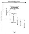
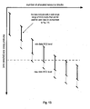
- Fig. 12 and 13 show essentially the same type of representation of the interrelation between MCS level, allocation size and transport block size as shown in Fig. 11 .
- the range of user data MCS levels identified by the control signaling for the respective allocation sizes is reduced (as indicated by the shorter vertical bars only being equivalent to a subset of the total range of MCS levels - as indicated by the dotted vertical bar illustrating the entire MCS level range as in Fig. 11 ).
- the MCS level of the control signaling or the CCE aggregation size level or the CCE indices
- control signaling is transmitted only with a low MCS level, so that the control signaling for the user data is interpreted to only relate to a lower sub-range of MCS levels. Accordingly, the for a given transport block size only a limited number of predetermined combinations of link adaptations may be signaled in comparison to the conventional case in Fig. 11 . This allows designing the control channel such that the number of bits required for the transport block size signaling is reduced.
- the mobile communication system may have a "two node architecture" consisting of at least one Access and Core Gateway (ACGW) and Node Bs.
- the ACGW may handle core network functions, such as routing calls and data connections to external networks, and it may also implement some RAN functions.
- the ACGW may be considered as to combine functions performed by GGSN and SGSN in today's 3G networks and RAN functions as for example radio resource control (RRC), header compression, ciphering/integrity protection and outer ARQ.
- RRC radio resource control
- the Node Bs may handle functions as for example segmentation/concatenation, scheduling and allocation of resources, multiplexing and physical layer functions.
- the eNodeBs are illustrated to control only one radio cell. Obviously, using beam-forming antennas and/or other techniques the eNodeBs may also control several radio cells or logical radio cells.
- a shared data channel may be used for communication on uplink and/or downlink on the air interface between mobile stations (UEs) and base stations (eNodeBs).
- This shared data channel may have a structure as shown in Fig. 1 , i.e. may be viewed as a concatenation of subframes as exemplarily depicted in Fig. 2 or Fig. 3 .
- the shared data channel may be defined as in the Technological Background section herein, as in 3GPP TR 25.814 or as the HS-DSCH as specified in 3GPP TS 25.308: "High Speed Downlink Packet Access (HSDPA); Overall description; Stage 2", v. 5.3.0, December 2002, available at http://www.3gpp.org.
- control signaling is related to uplink user data.
- Cat. 1, Cat. 2 and Cat. 3 information may thus be signaled from a base station to one or more mobile stations on downlink.
- the base station defines location and transport format (MCS level, MIMO, etc.) of uplink data transmission.
- the Cat. 1 information may be signaled on downlink and Cat. 2 and Cat. 3 information may be signaled on uplink.
- the base station defines only location of uplink transmission, while the mobile station defines transport format (e.g. MCS level) for its uplink data transmission.
- the base station may then define/interpret the Cat. 2 information transmitted on uplink depending on the MCS used for the Cat. 1 information transmitted in downlink.
- control signaling is related to the scheduling, transport format and/or HARQ parameters of user data.
- user data and the related control signaling are transmitted via a downlink channel.
- the user data and/or the related control signaling is transmitted via a downlink shared channel.
- the user data is transmitted via an uplink channel and the related control signaling is transmitted via a downlink channel.
- a MC-CDMA scheme or an OFDM scheme with pulse shaping may be used.
- OFDM/OQAM OFDM scheme with pulse shaping
- tailoring of MCS tables for the data transmission depending on the MCS level used for the control information may have the following benefits.
- a reduction of L1/L2 control signaling e.g. by reducing signaling bits for modulation scheme and/or payload size
- Optimizing the L1/L2 control signaling of Table 3 the Cat. 2 information can be reduced by 36% (14 to 9 bits) by omitting modulation scheme bits and reducing payload size bits to 3.
- the reduction of L1/L2 control signaling may lead to more resources available for data transmission, which may in turn lead to a higher system throughput.
- Improving the granularity of the data MCS levels by defining tailored MCS tables e.g. according to Table 9 and Table 10) may lead to a more accurate MCS selection, i.e. better data-rate adaptation to the channel state, which in turn may lead to a higher system throughput.
- a computing device or processor may for example be general purpose processors, digital signal processors (DSP), application specific integrated circuits (ASIC), field programmable gate arrays (FPGA) or other programmable logic devices, etc.
- DSP digital signal processors
- ASIC application specific integrated circuits
- FPGA field programmable gate arrays
- the various embodiments of the invention may also be performed or embodied by a combination of these devices.
- the various embodiments of the invention may also be implemented by means of software modules, which are executed by a processor or directly in hardware. Also a combination of software modules and a hardware implementation may be possible.
- the software modules may be stored on any kind of computer readable storage media, for example RAM, EPROM, EEPROM, flash memory, registers, hard disks, CD-ROM, DVD, etc.
Landscapes
- Engineering & Computer Science (AREA)
- Computer Networks & Wireless Communication (AREA)
- Signal Processing (AREA)
- Quality & Reliability (AREA)
- Databases & Information Systems (AREA)
- Mobile Radio Communication Systems (AREA)
Claims (32)
- Verfahren, das den folgenden Schritt umfasst:Interpretieren einer Information über wenigstens einen Link-Adaptation-Parameter zum Senden von Benutzerdaten, um den wenigstens einen Link-Adaptation-Parameter zum Senden der Benutzerdaten zu bestimmen, wobei die Information über den wenigstens einen Link-Adaptation-Parameter zum Senden der Benutzerdaten in Steuer-Signalisierung enthalten ist, unddadurch gekennzeichnet, dassdie Interpretation der Information von wenigstens einem Link-Adaptation-Parameter abhängt, der zum Senden der Steuer-Signalisierung verwendet wird.
- Verfahren nach Anspruch 1, das des Weiteren die folgenden Schritte umfasst:Empfangen der Steuer-Signalisierung, die die Information über den wenigstens einen Link-Adaptation-Parameter zum Senden der Benutzerdaten umfasst, an einer empfangenden Einheit, undEmpfangen der Benutzerdaten unter Verwendung des bestimmten wenigstens einen Link-Adaptation-Parameters an der empfangenden Einheit oder Senden derselben durch die empfangende Einheit.
- Verfahren nach Anspruch 1 oder 2, das des Weiteren den Schritt des Empfangens von Steuerdaten umfasst, die Link-Adaptation-Informationen umfassen, die den wenigstens einen Link-Adaptation-Parameter definieren, der zum Senden der Steuer-signalisierung verwendet wird.
- Verfahren nach Anspruch 1 oder 2, das des Weiteren den Schritt des Durchführens einer "blind detection" des wenigstens einen Link-Adaptation-Parameters zum Senden der Steuer-Signalisierung an einer empfangenden Einheit umfasst.
- Verfahren nach einem der Ansprüche 1 bis 4, wobei der wenigstens eine Link-Adaptation-Parameter zum Senden der Benutzerdaten wenigstens umfasst:wenigstens einen Parameter eines adaptiven Modulations-und-Kodier-Schemas,einen Nutzinformationsgrößen-Parameter,wenigstens einen Sendeleistungssteuerungs-Parameter,wenigstens einen MIMO-Parameter (Multiple Input Multiple Output parameter), oderwenigstens einen HARQ-Parameter (Hybrid Automatic Repeat Request parameter).
- Verfahren nach Anspruch 5, wobei der wenigstens eine Parameter eines adaptiven Modulations-und-Kodier-Schemas das Modulationsschema und die Kodierrate anzeigt, die zum Senden der Benutzerdaten verwendet werden.
- Verfahren nach Anspruch 6, wobei das Modulationsschema und die Kodierrate oder die Nutzinformationsgröße gemeinsam in einem einzelnen Bit-Muster innerhalb der Steuer-Signalisierung kodiert sind.
- Verfahren nach einem der Ansprüche 1 bis 7, wobei der wenigstens eine Link-Adaptation-Parameter, der zum Senden der Steuer-Signalisierung verwendet wird, das Modulations-und-Kodier-Schema und/oder der Sendeleistungspegel sind/ist, die/das/der zum Senden der Steuer-Signalisierung verwendet werden/wird.
- Verfahren nach einem der Ansprüche 1 bis 8, wobei der wenigstens eine Link-Adaptation-Parameter zum Senden der Benutzerdaten die Nutzinformationsgröße anzeigt.
- Verfahren nach Anspruch 9, wobei die Nutzinformationsgröße und die Anzahl von Ressourcen-Blöcken, die einem Benutzer zugewiesen werden, eine nicht lineare Beziehung haben.
- Verfahren nach einem der Ansprüche 1 bis 10, wobei die Steuer-Signalisierung ein Bit-Muster umfasst, das den wenigstens einen Link-Adaptation-Parameter zum Senden der Benutzerdaten anzeigt, und
das Verfahren des Weiteren den Schritt des Zuordnens des Bit-Musters zu Link-Adaptation-Parametern umfasst, die zum Senden der Benutzerdaten zu der empfangenden Einheit verwendet werden können, wobei das Zuordnen von dem wenigstens einen Link-Adaptation-Parameter abhängt, der zum Senden der Steuer-Signalisierung verwendet wird. - Verfahren nach einem der Ansprüche 1 bis 11, wobei mehrere Link-Adaptation-Tabellen oder -Gleichungen an einer empfangenden Einheit und/oder sendenden Einheit geführt werden, und jede Link-Adaptation-Tabelle oder -Gleichung die Zuordnung verfügbarer Bit-Muster zu Link-Adaptation-Parametern definiert, die zum Senden der Benutzerdaten verwendet werden können, und die Zuordnung von dem wenigstens einen Link-Adaption-Parameter abhängt, der zum Senden der Steuer-Signalisierung verwendet wird.
- Verfahren nach Anspruch 12, wobei der Schritt des Zuordnens des Bit-Musters zu Link-Adaptation-Parametern, die zum Senden der Benutzerdaten verwendet werden können, entsprechend einer ausgewählten der mehreren Link-Adaptation-Tabellen oder -Gleichungen durchgeführt wird, um den wenigstens einen Link-Adaptation-Parameter zu bestimmen, wobei die Auswahl der Link-Adaptation-Tabelle oder -Gleichung von dem wenigstens einen Link-Adaptation-Parameter abhängt, der zum Senden von Steuer-Signalisierung verwendet wird.
- Verfahren nach einem der Ansprüche 11 bis 13, wobei die Werte, die mit dem Bit-Muster dargestellt werden können, nur eine Teilgruppe aller möglichen Gruppen des wenigstens einen Link-Adaptation-Parameters zum Senden der Benutzerdaten abdecken und die abgedeckte Teilgruppe von dem wenigstens einen Link-Adaptation-Parameter abhängt, der zum Senden der Steuer-Signalisierung verwendet wird.
- Verfahren nach einem der Ansprüche 11 bis 14, wobei der wenigstens eine Link-Adaptation-Parameter zum Senden der Steuer-Signalisierung das Modulations-und-Kodier-Schema ist, das zum Senden der Steuer-Signalisierung verwendet wird, und
wobei das Bit-Muster in der Steuer-Signalisierung Link-Adaptation-Parametern zugeordnet wird, die einen Bereich spektraler Effizienzwerte für das Senden der Benutzerdaten abdecken, die genauso groß sind wie oder höher als die spektrale Effizienz, die sich durch das Modulations-und-Kodier-Schema zum Senden der Steuer-Signalisierung ergibt. - Verfahren nach einem der Ansprüche 11 bis 15, wobei eine Link-Adaptation-Tabelle oder -Gleichung, die die Zuordnung eines jeweiligen Bit-Musters zu jeweiligen verwendbaren Link-Adapation-Parametern definiert, eine gegebene Anzahl von Zuordnungen umfasst, und
wobei die Granularität der Schrittgröße zwischen spektralen Effizienzwerten, die sich durch eine erste Zuordnung und eine weitere zweite Zuordnung mehrerer Zuordnungen ergeben, einen Bereich spektraler Effizienzwerte für das Senden der Benutzerdaten um die spektrale Effizienz herum abdecken, die sich durch das Modulations-und-Kodier-Schema zum Senden der Steuer-Signalisierung ergibt, höher ist als diejenige für Zuordnungen zur Link-Adaptation-Parametern für das Senden der Benutzerdaten außerhalb des Bereiches. - Verfahren nach einem der Ansprüche 11 bis 13, wobei eine Link-Adaptation-Tabelle oder -Gleichung, die die Zuordnung eines jeweiligen Bit-Musters zur jeweiligen verwendbaren Link-Adapation-Parametern definiert, eine gegebene Anzahl von Zuordnungen umfasst, und
wobei die Granularität der Schrittgröße zwischen spektralen Effizienzwerten, die sich durch eine erste Zuordnung und eine weitere zweite Zuordnung mehrere Zuordnungen ergeben, einen Bereich spektraler Effizienzwerte für das Senden der Benutzerdaten um die spektrale Effizienz herum abdecken, die sich durch das Modulations-und-Kodier-Schema zum Senden der Steuer-Signalisierung ergibt, niedriger ist als diejenige für Zuordnungen zur Link-Adaptation-Parametern für das Senden der Benutzerdaten außerhalb des Bereiches. - Verfahren nach einem der Ansprüche 1 bis 17, wobei die Steuer-Signalisierung unter Verwendung eines festen oder vordefinierten Modulationsschemas gesendet wird.
- Verfahren nach einem der Ansprüche 1 bis 18, wobei die Steuer-Signalisierung auf Control Channel Elements abgebildet wird..
- Verfahren nach Anspruch 19, wobei die Anzahl der Control Channel Elements, auf die Steuer-Signalisierung abgebildet wird, ein Modulations-und-Kodier-Schema ergibt, das für das Senden der jeweiligen Steuer-Signalisierung genutzt wird.
- Verfahren nach einem der Ansprüche 1 bis 20, wobei sich die Steuer-Signalisierung auf das Scheduling, das Transport-Format und/oder auf HARQ-Parameter (Hybrid Automatic Repeat Request parameters) von Benutzerdaten bezieht.
- Verfahren nach einem der Ansprüche 1 bis 21, wobei die Benutzerdaten und die darauf bezogene Steuer-Signalisierung über einen Downlink-Kanal gesendet wird.
- Verfahren nach einem der Ansprüche 1 bis 21, wobei die Benutzerdaten und/oder die darauf bezogene Steuer-Signalisierung über einen Downlink Shared Channel gesendet werden/wird.
- Verfahren nach einem der Ansprüche 1 bis 21, wobei die Benutzerdaten über einen Uplink-Kanal gesendet werden und die darauf bezogene Steuer-Signalisierung über einen Downlink-Kanal gesendet wird.
- Verfahren nach einem der Ansprüche 1 bis 24, wobei ein OFDM-Schema (Orthogonal Frequency Division Multiplex scheme), ein MC-CDMA-Schema (Multi Carrier-Code Division Multiple Access scheme), oder ein OFDM-Schema mit Impulsformung zur Kommunikation in dem Mobilkommunikationssystem verwendet wird.
- Vorrichtung, die eine Verarbeitungseinheit umfasst, mit der eine Information über wenigstens einen Link-Adaptation-Parameter zum Senden von Benutzerdaten interpretiert wird, um den wenigstens einen Link-Adaptation-Parameter zum Senden der Benutzerdaten zu bestimmen, wobei die Information über den wenigstens einen Link-Adaptation-Parameter zum Senden der Benutzerdaten aus Steuer-Signalisierung besteht, und
dadurch gekennzeichnet, dass die Verarbeitungseinheit so betrieben werden kann, dass sie die Information in Abhängigkeit von wenigstens einem Link-Adaptation-Parameter interpretiert, der zum Senden der Steuer-Signalisierung verwendet wird. - Vorrichtung nach Anspruch 26, die des Weiteren umfasst:einen Empfänger zum Empfangen der Steuer-Signalisierung, die eine Information über den wenigstens einen Link-Adaptation-Parameter zum Senden der Benutzerdaten umfasst, an einer empfangenden Einheit, und zum Senden der Benutzerdaten unter Verwendung des bestimmten wenigstens einen Link-Adaptation-Parameters zum Senden der Benutzerdaten.
- Vorrichtung nach Anspruch 26, die des Weiteren umfasst:einen Empfänger zum Empfangen der Steuer-Signalisierung, die die Information über den wenigstens einen Link-Adaptation-Parameter zum Senden der Benutzerdaten umfasst, an einer empfangenden Einheit, undeinen Sender zum Senden der Benutzerdaten unter Verwendung des bestimmten wenigstens einen Link-Adaptation-Parameters zum Senden der Benutzerdaten.
- Vorrichtung nach einem der Ansprüche 26 bis 28, wobei die Vorrichtung eine Basisstation oder ein mobiles Endgerät ist.
- Vorrichtung nach einem der Ansprüche 26 bis 29, die des Weiteren Einrichtungen zum Durchführen aller Schritte des Verfahrens nach einem der Ansprüche 1 bis 25 umfasst.
- Computerlesbares Medium, auf dem Befehle gespeichert sind, die, wenn sie durch einen Prozessor einer Vorrichtung ausgeführt werden, die Vorrichtung veranlassen, Informationen über wenigstens einen Link-Adaptation-Parameter zum Senden von Benutzerdaten zu interpretieren, um den wenigstens einen Link-Adaptation-Parameter zum Senden der Benutzerdaten zu bestimmen, wobei die Information über den wenigstens einen Link-Adaptation-Parameter zum Senden der Benutzerdaten in Steuer-Signalisierung enthalten ist, und
dadurch gekennzeichnet, dass
die Interpretation der Information von wenigstens einem Link-Adaptation-Parameter abhängt, der zum Senden der Steuer-Signalisierung verwendet wird. - Computerlesbares Medium nach Anspruch 31, auf dem des Weiteren Befehle gespeichert sind, die, wenn sie durch den Prozessor ausgeführt werden, die Vorrichtung veranlassen, alle Schritte des Verfahrens nach einem der Ansprüche 1 bis 25 durchzuführen.
Priority Applications (4)
| Application Number | Priority Date | Filing Date | Title |
|---|---|---|---|
| EP07011823A EP1901496B1 (de) | 2006-09-12 | 2007-06-15 | Verbindungsanpassung in Abhängigkeit von der Kontrollsignalisierung |
| US12/440,906 US20100023830A1 (en) | 2006-09-12 | 2007-08-31 | Link adaptation dependent control signaling |
| JP2009527721A JP5113844B2 (ja) | 2006-09-12 | 2007-08-31 | リンク適応に依存した制御シグナリング |
| PCT/EP2007/007642 WO2008031511A1 (en) | 2006-09-12 | 2007-08-31 | Link adaptation dependent control signaling |
Applications Claiming Priority (2)
| Application Number | Priority Date | Filing Date | Title |
|---|---|---|---|
| EP06019092A EP1901491A1 (de) | 2006-09-12 | 2006-09-12 | Kontrollsignalisierung abhängig von der Verbindungsanpassung |
| EP07011823A EP1901496B1 (de) | 2006-09-12 | 2007-06-15 | Verbindungsanpassung in Abhängigkeit von der Kontrollsignalisierung |
Publications (2)
| Publication Number | Publication Date |
|---|---|
| EP1901496A1 EP1901496A1 (de) | 2008-03-19 |
| EP1901496B1 true EP1901496B1 (de) | 2010-09-01 |
Family
ID=38646573
Family Applications (1)
| Application Number | Title | Priority Date | Filing Date |
|---|---|---|---|
| EP07011823A Not-in-force EP1901496B1 (de) | 2006-09-12 | 2007-06-15 | Verbindungsanpassung in Abhängigkeit von der Kontrollsignalisierung |
Country Status (4)
| Country | Link |
|---|---|
| US (1) | US20100023830A1 (de) |
| EP (1) | EP1901496B1 (de) |
| JP (1) | JP5113844B2 (de) |
| WO (1) | WO2008031511A1 (de) |
Cited By (3)
| Publication number | Priority date | Publication date | Assignee | Title |
|---|---|---|---|---|
| WO2015103630A1 (en) * | 2014-01-06 | 2015-07-09 | Intel IP Corporation | Systems and methods for modulation and coding scheme selection and configuration |
| US9467269B2 (en) | 2014-01-06 | 2016-10-11 | Intel IP Corporation | Systems and methods for modulation and coding scheme selection and configuration |
| US10959120B2 (en) | 2005-12-22 | 2021-03-23 | Qualcomm Incorporated | Methods and apparatus related to selecting control channel reporting formats |
Families Citing this family (68)
| Publication number | Priority date | Publication date | Assignee | Title |
|---|---|---|---|---|
| WO2007055292A1 (ja) * | 2005-11-10 | 2007-05-18 | Matsushita Electric Industrial Co., Ltd. | 無線送信装置及び無線送信方法 |
| ES2836890T3 (es) | 2006-10-31 | 2021-06-28 | Ericsson Telefon Ab L M | Método y aparato para control de error en sistemas de telecomunicaciones |
| JP5035338B2 (ja) * | 2007-05-21 | 2012-09-26 | 富士通株式会社 | データ再送方法及び,これを適用する無線通信システム |
| KR100937030B1 (ko) * | 2007-05-31 | 2010-01-15 | 한국전자통신연구원 | 디지털 방송 신호의 전송 방법, 전송 장치, 수신 방법 및수신 장치 |
| EP2168294A4 (de) * | 2007-06-14 | 2013-02-27 | Ericsson Telefon Ab L M | Datenblockgrössenverwaltung in einem kommunikationssystem mit automatischen hybdrid-wiederholungsaufforderungen mit soft-combining |
| US8739013B2 (en) * | 2007-09-28 | 2014-05-27 | Lg Electronics Inc. | Method for detecting control information in wireless communication system |
| EP2193615B1 (de) | 2007-09-28 | 2012-09-19 | LG Electronics Inc. | Verfahren zur erkennung von steuerungsinformationen in drahtlosen kommunikationssystemen |
| KR101448309B1 (ko) * | 2007-09-28 | 2014-10-08 | 엘지전자 주식회사 | 무선통신 시스템에서 하향링크 제어채널 모니터링 방법 |
| WO2009087742A1 (ja) * | 2008-01-04 | 2009-07-16 | Panasonic Corporation | 無線通信基地局装置、無線通信移動局装置および制御チャネル割当方法 |
| KR101531377B1 (ko) | 2008-03-27 | 2015-06-25 | 코닌클리케 필립스 엔.브이. | 모바일 네트워크에서의 통신을 위한 방법 |
| EP2260580B1 (de) | 2008-04-03 | 2015-09-30 | Telefonaktiebolaget L M Ericsson (PUBL) | Verfahren und vorrichtung zum übermitteln von vorcodierungsinformationen in einem mimo-system |
| US9172509B2 (en) * | 2008-04-11 | 2015-10-27 | Interdigital Patent Holdings, Inc. | Method for transmission time interval bundling in the uplink |
| US9276723B1 (en) * | 2008-05-12 | 2016-03-01 | Clearwire Ip Holdings Llc | Systems and methods of transmission of user data packets |
| US8488553B2 (en) * | 2008-06-05 | 2013-07-16 | Alcatel Lucent | Method for providing seamless transition between networks following different protocols |
| CN101610545B (zh) * | 2008-06-19 | 2011-10-05 | 展讯通信(上海)有限公司 | 时分同步码分多址系统中的数据包收发方法及设备 |
| WO2010013960A2 (en) * | 2008-07-31 | 2010-02-04 | Samsung Electronics Co., Ltd. | Method and apparatus for allocating resource of multiple carriers in ofdma system |
| EP2342858B1 (de) * | 2008-09-22 | 2013-01-02 | Nokia Siemens Networks Oy | Verfahren und vorrichtung zur bereitstellung von signalisierung von redundanzversionen |
| EP2353249A1 (de) * | 2008-10-20 | 2011-08-10 | Nokia Siemens Networks Oy | Sounding-kanalvorrichtung und verfahren |
| US8310981B2 (en) * | 2008-10-22 | 2012-11-13 | Qualcomm Incorporated | Common and dedicated modulation and coding scheme for a multicarrier system |
| KR101276854B1 (ko) * | 2008-10-27 | 2013-06-18 | 엘지전자 주식회사 | 셀룰러 시스템에 있어서, 하향링크 제어 메시지 구성 정보 통지 방법 |
| WO2010050724A2 (en) | 2008-10-27 | 2010-05-06 | Lg Electronics Inc. | Method for informing user equipment of downlink control message construction information in cellular system |
| KR101557676B1 (ko) | 2008-10-31 | 2015-10-06 | 삼성전자주식회사 | 이동무선 통신시스템의 하향링크 제어채널의 페이로드 크기결정장치 및 방법 |
| US8737319B2 (en) * | 2008-12-15 | 2014-05-27 | Samsung Electronics Co., Ltd. | Method and apparatus for reducing map overhead in a broadand wireless communication system |
| KR101697596B1 (ko) | 2009-01-29 | 2017-01-18 | 엘지전자 주식회사 | 전송 전력을 제어하는 방법 및 이를 위한 장치 |
| JP2010206403A (ja) * | 2009-03-02 | 2010-09-16 | Toshiba Corp | 基地局、端末および無線通信システム |
| US9236985B2 (en) | 2009-04-23 | 2016-01-12 | Qualcomm Incorporated | Method and apparatus for control and data multiplexing in a MIMO communication system |
| KR20100138838A (ko) * | 2009-06-24 | 2010-12-31 | 엘지전자 주식회사 | 광대역 무선 접속 시스템에서 변조 및 부호화 기법 결정 방법 |
| CN101998429A (zh) * | 2009-08-13 | 2011-03-30 | 大唐移动通信设备有限公司 | 载波聚合系统中cce聚合长度指示方法、获取方法和设备 |
| US9236992B2 (en) * | 2009-09-18 | 2016-01-12 | Lg Electronics Inc. | Method and apparatus for transceiving scheduling signals in a multi-carrier wireless communication system |
| EP2364051B1 (de) * | 2010-03-03 | 2017-05-03 | BlackBerry Limited | Verfahren und Vorrichtung zur Anzeige des Platzbedarfs um die Funktionen eines Gerätes zu kommunizieren |
| EP2545729A4 (de) * | 2010-03-09 | 2016-11-23 | Ericsson Telefon Ab L M | Verfahren und anordnung zur verbindungsadaption in einem kommunikationssystem, einstellung von verbindungsadaptionsparametern je nach daten- und steuerkanallast |
| CN101834629B (zh) * | 2010-04-06 | 2014-10-22 | 中兴通讯股份有限公司 | 一种指示传输参数的方法及系统 |
| US9160486B2 (en) | 2010-05-13 | 2015-10-13 | Lg Electronics Inc. | Method and apparatus for multiplexing control information and data, and for transmitting the multiplexed control information and data in a MIMO wireless communication system |
| EP2583404A1 (de) | 2010-06-18 | 2013-04-24 | Kyocera Corporation | Steuerkanalarchitektur mit über mehrere subframes auf verschiedenen trägern verteilten steuerinformationen |
| US9094175B2 (en) * | 2010-07-16 | 2015-07-28 | Qualcomm, Incorporated | Method and apparatus for saving power by using signal field of preamble |
| US9398544B2 (en) | 2010-11-05 | 2016-07-19 | Qualcomm Incorporated | Dynamic uplink power control |
| CN102131279B (zh) * | 2010-11-26 | 2013-08-28 | 华为技术有限公司 | 一种发送功率调整方法和装置 |
| KR20140093273A (ko) | 2011-11-15 | 2014-07-25 | 옵티스 셀룰러 테크놀리지, 엘엘씨 | 제어 채널 요소 할당 장치 및 방법 |
| KR20130059686A (ko) * | 2011-11-29 | 2013-06-07 | 한국전자통신연구원 | 무선 통신 시스템에서 무선 신호 송수신 방법 및 이를 지원하는 장치 |
| US9560603B2 (en) * | 2012-02-29 | 2017-01-31 | Kyocera Corporation | Mobile communication system, mobile communication method, radio base station, and radio terminal |
| CN103580788A (zh) | 2012-07-27 | 2014-02-12 | 电信科学技术研究院 | 一种传输mcs指示信息的方法及装置 |
| US9537640B2 (en) * | 2012-08-27 | 2017-01-03 | Nokia Solutions And Networks Oy | Transmission adaptation |
| US10085154B2 (en) * | 2012-10-17 | 2018-09-25 | Huawei Technologies Co., Ltd. | System and method for dynamic inter-cell interference coordination |
| US10432370B2 (en) * | 2013-01-14 | 2019-10-01 | Qualcomm Incorporated | Transmission and processing of higher order modulation |
| CN103944855B (zh) | 2013-01-18 | 2018-08-17 | 中兴通讯股份有限公司 | 调制处理方法及装置 |
| JP5894105B2 (ja) * | 2013-04-04 | 2016-03-23 | 株式会社Nttドコモ | 無線基地局、ユーザ端末及び無線通信方法 |
| GB2513122A (en) * | 2013-04-15 | 2014-10-22 | Vodafone Intellectual Property Licensing Ltd | Uplink control channel overhead reduction |
| US20140328155A1 (en) * | 2013-05-01 | 2014-11-06 | Qualcomm Incorporated | Increased information carrying capacity in an enhanced general packet radio service control channel |
| US9497682B2 (en) * | 2013-06-07 | 2016-11-15 | Intel Corporation | Central processing unit and methods for supporting coordinated multipoint transmission in an LTE network |
| KR102059135B1 (ko) * | 2013-08-14 | 2019-12-24 | 삼성전자주식회사 | 무선 통신 시스템에서 장치 간 통신을 위한 송신 제어 장치 및 방법 |
| US9743432B2 (en) * | 2013-09-23 | 2017-08-22 | Qualcomm Incorporated | LTE-U uplink waveform and variable multi-subframe scheduling |
| US10021677B2 (en) * | 2014-10-31 | 2018-07-10 | Qualcomm Incorporated | Two-stage PDCCH with DCI flag and DCI format size indicator |
| WO2016089184A1 (en) * | 2014-12-05 | 2016-06-09 | Lg Electronics Inc. | Method and apparatus for supporting variable transport block size without associated downlink control information in wireless communication system |
| US10701620B2 (en) | 2015-03-10 | 2020-06-30 | Telefonaktiebolaget Lm Ericsson (Publ) | Methods, network node and wireless device for handling access information |
| US20160270102A1 (en) * | 2015-03-14 | 2016-09-15 | Qualcomm Incorporated | Distributed scheduling to control interference for data transactions using grant-less transmissions |
| US10135562B2 (en) | 2015-05-28 | 2018-11-20 | Huawei Technologies Co., Ltd. | Apparatus and method for link adaptation in uplink grant-less random access |
| TWI606743B (zh) * | 2015-10-02 | 2017-11-21 | 財團法人工業技術研究院 | 多用戶疊加傳輸方法以及使用所述方法的基地台 |
| WO2017069668A1 (en) | 2015-10-21 | 2017-04-27 | Telefonaktiebolaget Lm Ericsson (Publ) | Methods, network nodes and wireless device for handling access information |
| CN105848303B (zh) * | 2016-03-16 | 2019-09-17 | 中国联合网络通信集团有限公司 | 终端多类型网络接入系统及方法、终端、网络侧设备 |
| US9853667B2 (en) * | 2016-05-25 | 2017-12-26 | Apple Inc. | Noise and interference estimation for colliding neighbor reference signals |
| US10333649B1 (en) * | 2016-07-12 | 2019-06-25 | Sprint Spectrum L.P. | Selection of modulation and coding scheme (MCS) based on packet length |
| US10775361B2 (en) * | 2016-07-22 | 2020-09-15 | Qualcomm Incorporated | Monitoring control channel with different encoding schemes |
| CN107733553B (zh) * | 2016-08-12 | 2022-01-28 | 中兴通讯股份有限公司 | 传输块的发送方法和装置、接收方法和装置 |
| US11546858B2 (en) * | 2018-03-23 | 2023-01-03 | Qualcomm Incorporated | Power control techniques for uplink control information transmissions in wireless communications |
| CN109644081B (zh) * | 2018-11-28 | 2021-08-24 | 北京小米移动软件有限公司 | 下行控制信令的检测方法、装置及系统 |
| WO2020164753A1 (en) | 2019-02-13 | 2020-08-20 | Fraunhofer-Gesellschaft zur Förderung der angewandten Forschung e.V. | Decoder and decoding method selecting an error concealment mode, and encoder and encoding method |
| US12107675B2 (en) * | 2020-10-15 | 2024-10-01 | Samsung Electronics Co., Ltd. | Method and apparatus for improving a throughput for a user equipment in a wireless network system |
| CN115348484B (zh) * | 2022-07-07 | 2024-06-04 | 中国船舶重工集团公司第七一五研究所 | 一种基于自校信号监测的信号采集链路自动切换方法 |
Family Cites Families (17)
| Publication number | Priority date | Publication date | Assignee | Title |
|---|---|---|---|---|
| US20030016702A1 (en) * | 2001-03-30 | 2003-01-23 | Bender Paul E. | Method and system for maximizing standby time in monitoring a control channel |
| EP1255369A1 (de) * | 2001-05-04 | 2002-11-06 | TELEFONAKTIEBOLAGET LM ERICSSON (publ) | Verbindungsanpassung für drahtlose Kommunikationssysteme mit mehreren Eingängen und mehreren Ausgängen |
| JP3637884B2 (ja) * | 2001-06-01 | 2005-04-13 | ソニー株式会社 | 逆拡散装置、伝播路推定装置、受信装置ならびに干渉抑圧装置、逆拡散、伝播路推定、受信および干渉抑圧方法、該プログラムおよび該プログラムを記録した記録媒体 |
| JP4188818B2 (ja) * | 2001-06-25 | 2008-12-03 | ノキア コーポレイション | Tfci信号システムによるmcs及びマルチコードの最適化 |
| US7171229B2 (en) | 2001-10-31 | 2007-01-30 | Koninklijke Philips Electronics N.V. | Method for operating a radio communication system |
| GB0302024D0 (en) | 2003-01-29 | 2003-02-26 | Roke Manor Research | Transport format combination selection in the uplink for the flexible layer one |
| US7945280B2 (en) * | 2003-02-20 | 2011-05-17 | Fujitsu Limited | Radio channel control method and receiving apparatus |
| KR100985104B1 (ko) * | 2003-09-03 | 2010-10-05 | 엘지전자 주식회사 | 재전송 패킷의 전력제어방법 |
| EP1530387A1 (de) * | 2003-11-06 | 2005-05-11 | Matsushita Electric Industrial Co., Ltd. | Sendeleistungsfestlegung während Kanalzuweisung für Interferenzausgleich in einem zellularen Mobilkommunikationssystem |
| US10355825B2 (en) | 2004-07-21 | 2019-07-16 | Qualcomm Incorporated | Shared signaling channel for a communication system |
| US8031583B2 (en) * | 2005-03-30 | 2011-10-04 | Motorola Mobility, Inc. | Method and apparatus for reducing round trip latency and overhead within a communication system |
| US7706330B2 (en) * | 2005-10-03 | 2010-04-27 | Motorola, Inc. | Method and system for link adaptation in a wireless multi-carrier communication system |
| CN102882641B (zh) * | 2006-02-03 | 2016-07-06 | 交互数字技术公司 | 无线发射/接收单元及其执行的方法 |
| US20070189231A1 (en) * | 2006-02-14 | 2007-08-16 | Chang Li F | Method and system for implementing a bufferless HARQ processor |
| US7903614B2 (en) * | 2006-04-27 | 2011-03-08 | Interdigital Technology Corporation | Method and apparatus for selecting link adaptation parameters for CDMA-based wireless communication systems |
| KR100913473B1 (ko) * | 2008-03-20 | 2009-08-25 | 엘지전자 주식회사 | 무선 통신 시스템에서 pdcch 모니터링 방법 |
| WO2011008023A2 (en) * | 2009-07-15 | 2011-01-20 | Lg Electronics Inc. | Method and apparatus for controlling uplink power in a wireless communication system |
-
2007
- 2007-06-15 EP EP07011823A patent/EP1901496B1/de not_active Not-in-force
- 2007-08-31 JP JP2009527721A patent/JP5113844B2/ja not_active Expired - Fee Related
- 2007-08-31 US US12/440,906 patent/US20100023830A1/en not_active Abandoned
- 2007-08-31 WO PCT/EP2007/007642 patent/WO2008031511A1/en active Application Filing
Cited By (5)
| Publication number | Priority date | Publication date | Assignee | Title |
|---|---|---|---|---|
| US10959120B2 (en) | 2005-12-22 | 2021-03-23 | Qualcomm Incorporated | Methods and apparatus related to selecting control channel reporting formats |
| WO2015103630A1 (en) * | 2014-01-06 | 2015-07-09 | Intel IP Corporation | Systems and methods for modulation and coding scheme selection and configuration |
| US9467269B2 (en) | 2014-01-06 | 2016-10-11 | Intel IP Corporation | Systems and methods for modulation and coding scheme selection and configuration |
| US10015036B2 (en) | 2014-01-06 | 2018-07-03 | Intel IP Corporation | Systems and methods for modulation and coding scheme selection and configuration |
| US11122551B2 (en) | 2014-01-06 | 2021-09-14 | Apple Inc. | Systems and methods for modulation and coding scheme selection and configuration |
Also Published As
| Publication number | Publication date |
|---|---|
| JP2010503352A (ja) | 2010-01-28 |
| WO2008031511A1 (en) | 2008-03-20 |
| JP5113844B2 (ja) | 2013-01-09 |
| EP1901496A1 (de) | 2008-03-19 |
| US20100023830A1 (en) | 2010-01-28 |
Similar Documents
| Publication | Publication Date | Title |
|---|---|---|
| EP1901496B1 (de) | Verbindungsanpassung in Abhängigkeit von der Kontrollsignalisierung | |
| US11438884B2 (en) | Configuration of control channels in a mobile communication system | |
| US20220123909A1 (en) | Control channel signalling for triggering the independent transmission of a channel quality indicator | |
| EP1901491A1 (de) | Kontrollsignalisierung abhängig von der Verbindungsanpassung | |
| US8428007B2 (en) | Resource allocation size dependent transport block size signaling | |
| KR101949619B1 (ko) | 전송 포맷 및 리던던시 버전용 공통 시그널링 필드를 이용하는 제어 시그널링 | |
| AU2020201448A1 (en) | Control channel signalling for triggering the independent transmission of a channel quality indicator | |
| AU2009243805B2 (en) | Control channel signalling for triggering the independent transmission of a channel quality indicator |
Legal Events
| Date | Code | Title | Description |
|---|---|---|---|
| PUAI | Public reference made under article 153(3) epc to a published international application that has entered the european phase |
Free format text: ORIGINAL CODE: 0009012 |
|
| AK | Designated contracting states |
Kind code of ref document: A1 Designated state(s): AT BE BG CH CY CZ DE DK EE ES FI FR GB GR HU IE IS IT LI LT LU LV MC MT NL PL PT RO SE SI SK TR |
|
| AX | Request for extension of the european patent |
Extension state: AL BA HR MK YU |
|
| 17P | Request for examination filed |
Effective date: 20080827 |
|
| 17Q | First examination report despatched |
Effective date: 20081001 |
|
| RAP1 | Party data changed (applicant data changed or rights of an application transferred) |
Owner name: PANASONIC CORPORATION |
|
| AKX | Designation fees paid |
Designated state(s): AT BE BG CH CY CZ DE DK EE ES FI FR GB GR HU IE IS IT LI LT LU LV MC MT NL PL PT RO SE SI SK TR |
|
| GRAP | Despatch of communication of intention to grant a patent |
Free format text: ORIGINAL CODE: EPIDOSNIGR1 |
|
| RTI1 | Title (correction) |
Free format text: LINK ADAPTATION DEPENDENT ON CONTROL SIGNALING |
|
| GRAS | Grant fee paid |
Free format text: ORIGINAL CODE: EPIDOSNIGR3 |
|
| GRAA | (expected) grant |
Free format text: ORIGINAL CODE: 0009210 |
|
| AK | Designated contracting states |
Kind code of ref document: B1 Designated state(s): AT BE BG CH CY CZ DE DK EE ES FI FR GB GR HU IE IS IT LI LT LU LV MC MT NL PL PT RO SE SI SK TR |
|
| REG | Reference to a national code |
Ref country code: GB Ref legal event code: FG4D |
|
| REG | Reference to a national code |
Ref country code: CH Ref legal event code: EP |
|
| REG | Reference to a national code |
Ref country code: IE Ref legal event code: FG4D |
|
| REF | Corresponds to: |
Ref document number: 602007008805 Country of ref document: DE Date of ref document: 20101014 Kind code of ref document: P |
|
| REG | Reference to a national code |
Ref country code: NL Ref legal event code: VDEP Effective date: 20100901 |
|
| PG25 | Lapsed in a contracting state [announced via postgrant information from national office to epo] |
Ref country code: FI Free format text: LAPSE BECAUSE OF FAILURE TO SUBMIT A TRANSLATION OF THE DESCRIPTION OR TO PAY THE FEE WITHIN THE PRESCRIBED TIME-LIMIT Effective date: 20100901 Ref country code: AT Free format text: LAPSE BECAUSE OF FAILURE TO SUBMIT A TRANSLATION OF THE DESCRIPTION OR TO PAY THE FEE WITHIN THE PRESCRIBED TIME-LIMIT Effective date: 20100901 Ref country code: LT Free format text: LAPSE BECAUSE OF FAILURE TO SUBMIT A TRANSLATION OF THE DESCRIPTION OR TO PAY THE FEE WITHIN THE PRESCRIBED TIME-LIMIT Effective date: 20100901 |
|
| LTIE | Lt: invalidation of european patent or patent extension |
Effective date: 20100901 |
|
| PG25 | Lapsed in a contracting state [announced via postgrant information from national office to epo] |
Ref country code: CY Free format text: LAPSE BECAUSE OF FAILURE TO SUBMIT A TRANSLATION OF THE DESCRIPTION OR TO PAY THE FEE WITHIN THE PRESCRIBED TIME-LIMIT Effective date: 20100901 Ref country code: PL Free format text: LAPSE BECAUSE OF FAILURE TO SUBMIT A TRANSLATION OF THE DESCRIPTION OR TO PAY THE FEE WITHIN THE PRESCRIBED TIME-LIMIT Effective date: 20100901 Ref country code: SI Free format text: LAPSE BECAUSE OF FAILURE TO SUBMIT A TRANSLATION OF THE DESCRIPTION OR TO PAY THE FEE WITHIN THE PRESCRIBED TIME-LIMIT Effective date: 20100901 |
|
| PG25 | Lapsed in a contracting state [announced via postgrant information from national office to epo] |
Ref country code: LV Free format text: LAPSE BECAUSE OF FAILURE TO SUBMIT A TRANSLATION OF THE DESCRIPTION OR TO PAY THE FEE WITHIN THE PRESCRIBED TIME-LIMIT Effective date: 20100901 Ref country code: NL Free format text: LAPSE BECAUSE OF FAILURE TO SUBMIT A TRANSLATION OF THE DESCRIPTION OR TO PAY THE FEE WITHIN THE PRESCRIBED TIME-LIMIT Effective date: 20100901 Ref country code: GR Free format text: LAPSE BECAUSE OF FAILURE TO SUBMIT A TRANSLATION OF THE DESCRIPTION OR TO PAY THE FEE WITHIN THE PRESCRIBED TIME-LIMIT Effective date: 20101202 Ref country code: SE Free format text: LAPSE BECAUSE OF FAILURE TO SUBMIT A TRANSLATION OF THE DESCRIPTION OR TO PAY THE FEE WITHIN THE PRESCRIBED TIME-LIMIT Effective date: 20100901 |
|
| PG25 | Lapsed in a contracting state [announced via postgrant information from national office to epo] |
Ref country code: IS Free format text: LAPSE BECAUSE OF FAILURE TO SUBMIT A TRANSLATION OF THE DESCRIPTION OR TO PAY THE FEE WITHIN THE PRESCRIBED TIME-LIMIT Effective date: 20110101 Ref country code: RO Free format text: LAPSE BECAUSE OF FAILURE TO SUBMIT A TRANSLATION OF THE DESCRIPTION OR TO PAY THE FEE WITHIN THE PRESCRIBED TIME-LIMIT Effective date: 20100901 Ref country code: PT Free format text: LAPSE BECAUSE OF FAILURE TO SUBMIT A TRANSLATION OF THE DESCRIPTION OR TO PAY THE FEE WITHIN THE PRESCRIBED TIME-LIMIT Effective date: 20110103 Ref country code: IT Free format text: LAPSE BECAUSE OF FAILURE TO SUBMIT A TRANSLATION OF THE DESCRIPTION OR TO PAY THE FEE WITHIN THE PRESCRIBED TIME-LIMIT Effective date: 20100901 Ref country code: CZ Free format text: LAPSE BECAUSE OF FAILURE TO SUBMIT A TRANSLATION OF THE DESCRIPTION OR TO PAY THE FEE WITHIN THE PRESCRIBED TIME-LIMIT Effective date: 20100901 Ref country code: SK Free format text: LAPSE BECAUSE OF FAILURE TO SUBMIT A TRANSLATION OF THE DESCRIPTION OR TO PAY THE FEE WITHIN THE PRESCRIBED TIME-LIMIT Effective date: 20100901 Ref country code: EE Free format text: LAPSE BECAUSE OF FAILURE TO SUBMIT A TRANSLATION OF THE DESCRIPTION OR TO PAY THE FEE WITHIN THE PRESCRIBED TIME-LIMIT Effective date: 20100901 |
|
| PG25 | Lapsed in a contracting state [announced via postgrant information from national office to epo] |
Ref country code: ES Free format text: LAPSE BECAUSE OF FAILURE TO SUBMIT A TRANSLATION OF THE DESCRIPTION OR TO PAY THE FEE WITHIN THE PRESCRIBED TIME-LIMIT Effective date: 20101212 Ref country code: BE Free format text: LAPSE BECAUSE OF FAILURE TO SUBMIT A TRANSLATION OF THE DESCRIPTION OR TO PAY THE FEE WITHIN THE PRESCRIBED TIME-LIMIT Effective date: 20100901 |
|
| PLBE | No opposition filed within time limit |
Free format text: ORIGINAL CODE: 0009261 |
|
| STAA | Information on the status of an ep patent application or granted ep patent |
Free format text: STATUS: NO OPPOSITION FILED WITHIN TIME LIMIT |
|
| 26N | No opposition filed |
Effective date: 20110606 |
|
| PG25 | Lapsed in a contracting state [announced via postgrant information from national office to epo] |
Ref country code: DK Free format text: LAPSE BECAUSE OF FAILURE TO SUBMIT A TRANSLATION OF THE DESCRIPTION OR TO PAY THE FEE WITHIN THE PRESCRIBED TIME-LIMIT Effective date: 20100901 |
|
| REG | Reference to a national code |
Ref country code: DE Ref legal event code: R097 Ref document number: 602007008805 Country of ref document: DE Effective date: 20110606 |
|
| PG25 | Lapsed in a contracting state [announced via postgrant information from national office to epo] |
Ref country code: MT Free format text: LAPSE BECAUSE OF FAILURE TO SUBMIT A TRANSLATION OF THE DESCRIPTION OR TO PAY THE FEE WITHIN THE PRESCRIBED TIME-LIMIT Effective date: 20100901 |
|
| REG | Reference to a national code |
Ref country code: CH Ref legal event code: PL |
|
| REG | Reference to a national code |
Ref country code: IE Ref legal event code: MM4A |
|
| PG25 | Lapsed in a contracting state [announced via postgrant information from national office to epo] |
Ref country code: IE Free format text: LAPSE BECAUSE OF NON-PAYMENT OF DUE FEES Effective date: 20110615 Ref country code: LI Free format text: LAPSE BECAUSE OF NON-PAYMENT OF DUE FEES Effective date: 20110630 Ref country code: CH Free format text: LAPSE BECAUSE OF NON-PAYMENT OF DUE FEES Effective date: 20110630 |
|
| PG25 | Lapsed in a contracting state [announced via postgrant information from national office to epo] |
Ref country code: MC Free format text: LAPSE BECAUSE OF NON-PAYMENT OF DUE FEES Effective date: 20110630 |
|
| PG25 | Lapsed in a contracting state [announced via postgrant information from national office to epo] |
Ref country code: LU Free format text: LAPSE BECAUSE OF NON-PAYMENT OF DUE FEES Effective date: 20110615 |
|
| PG25 | Lapsed in a contracting state [announced via postgrant information from national office to epo] |
Ref country code: BG Free format text: LAPSE BECAUSE OF FAILURE TO SUBMIT A TRANSLATION OF THE DESCRIPTION OR TO PAY THE FEE WITHIN THE PRESCRIBED TIME-LIMIT Effective date: 20101201 Ref country code: TR Free format text: LAPSE BECAUSE OF FAILURE TO SUBMIT A TRANSLATION OF THE DESCRIPTION OR TO PAY THE FEE WITHIN THE PRESCRIBED TIME-LIMIT Effective date: 20100901 |
|
| PG25 | Lapsed in a contracting state [announced via postgrant information from national office to epo] |
Ref country code: HU Free format text: LAPSE BECAUSE OF FAILURE TO SUBMIT A TRANSLATION OF THE DESCRIPTION OR TO PAY THE FEE WITHIN THE PRESCRIBED TIME-LIMIT Effective date: 20100901 |
|
| REG | Reference to a national code |
Ref country code: GB Ref legal event code: 732E Free format text: REGISTERED BETWEEN 20140612 AND 20140618 |
|
| REG | Reference to a national code |
Ref country code: DE Ref legal event code: R082 Ref document number: 602007008805 Country of ref document: DE Representative=s name: GRUENECKER, KINKELDEY, STOCKMAIR & SCHWANHAEUS, DE Ref country code: DE Ref legal event code: R079 Ref document number: 602007008805 Country of ref document: DE Free format text: PREVIOUS MAIN CLASS: H04L0012560000 Ipc: H04L0012801000 |
|
| REG | Reference to a national code |
Ref country code: DE Ref legal event code: R079 Ref document number: 602007008805 Country of ref document: DE Free format text: PREVIOUS MAIN CLASS: H04L0012560000 Ipc: H04L0012801000 Effective date: 20140711 Ref country code: DE Ref legal event code: R081 Ref document number: 602007008805 Country of ref document: DE Owner name: PANASONIC INTELLECTUAL PROPERTY CORPORATION OF, US Free format text: FORMER OWNER: PANASONIC CORPORATION, KADOMA-SHI, OSAKA, JP Effective date: 20140711 Ref country code: DE Ref legal event code: R082 Ref document number: 602007008805 Country of ref document: DE Representative=s name: GRUENECKER, KINKELDEY, STOCKMAIR & SCHWANHAEUS, DE Effective date: 20140711 Ref country code: DE Ref legal event code: R082 Ref document number: 602007008805 Country of ref document: DE Representative=s name: GRUENECKER PATENT- UND RECHTSANWAELTE PARTG MB, DE Effective date: 20140711 |
|
| REG | Reference to a national code |
Ref country code: FR Ref legal event code: TP Owner name: PANASONIC INTELLECTUAL PROPERTY CORPORATION OF, US Effective date: 20140722 |
|
| REG | Reference to a national code |
Ref country code: FR Ref legal event code: PLFP Year of fee payment: 10 |
|
| REG | Reference to a national code |
Ref country code: FR Ref legal event code: PLFP Year of fee payment: 11 |
|
| REG | Reference to a national code |
Ref country code: FR Ref legal event code: PLFP Year of fee payment: 12 |
|
| REG | Reference to a national code |
Ref country code: DE Ref legal event code: R079 Ref document number: 602007008805 Country of ref document: DE Free format text: PREVIOUS MAIN CLASS: H04L0012801000 Ipc: H04L0047100000 |
|
| PGFP | Annual fee paid to national office [announced via postgrant information from national office to epo] |
Ref country code: GB Payment date: 20220425 Year of fee payment: 16 Ref country code: FR Payment date: 20220408 Year of fee payment: 16 Ref country code: DE Payment date: 20220420 Year of fee payment: 16 |
|
| REG | Reference to a national code |
Ref country code: DE Ref legal event code: R119 Ref document number: 602007008805 Country of ref document: DE |
|
| GBPC | Gb: european patent ceased through non-payment of renewal fee |
Effective date: 20230615 |
|
| PG25 | Lapsed in a contracting state [announced via postgrant information from national office to epo] |
Ref country code: DE Free format text: LAPSE BECAUSE OF NON-PAYMENT OF DUE FEES Effective date: 20240103 Ref country code: GB Free format text: LAPSE BECAUSE OF NON-PAYMENT OF DUE FEES Effective date: 20230615 |
|
| PG25 | Lapsed in a contracting state [announced via postgrant information from national office to epo] |
Ref country code: FR Free format text: LAPSE BECAUSE OF NON-PAYMENT OF DUE FEES Effective date: 20230630 |