EP1600254A1 - Vorschubeinheit für eine Maschine zum Bearbeiten von Werkstücken sowie Verfahren zum Bearbeiten solcher Werkstücke - Google Patents
Vorschubeinheit für eine Maschine zum Bearbeiten von Werkstücken sowie Verfahren zum Bearbeiten solcher Werkstücke Download PDFInfo
- Publication number
- EP1600254A1 EP1600254A1 EP05010415A EP05010415A EP1600254A1 EP 1600254 A1 EP1600254 A1 EP 1600254A1 EP 05010415 A EP05010415 A EP 05010415A EP 05010415 A EP05010415 A EP 05010415A EP 1600254 A1 EP1600254 A1 EP 1600254A1
- Authority
- EP
- European Patent Office
- Prior art keywords
- feed
- workpieces
- feed unit
- unit
- woods
- Prior art date
- Legal status (The legal status is an assumption and is not a legal conclusion. Google has not performed a legal analysis and makes no representation as to the accuracy of the status listed.)
- Granted
Links
- 238000000034 method Methods 0.000 title claims abstract description 30
- 238000003754 machining Methods 0.000 title claims description 25
- 238000012545 processing Methods 0.000 claims abstract description 52
- 239000002023 wood Substances 0.000 claims description 31
- 238000012546 transfer Methods 0.000 claims description 10
- 238000005553 drilling Methods 0.000 claims description 2
- 238000013461 design Methods 0.000 description 3
- 229910052751 metal Inorganic materials 0.000 description 2
- 239000002184 metal Substances 0.000 description 2
- 238000003801 milling Methods 0.000 description 2
- 238000012549 training Methods 0.000 description 2
- 229910052782 aluminium Inorganic materials 0.000 description 1
- XAGFODPZIPBFFR-UHFFFAOYSA-N aluminium Chemical compound [Al] XAGFODPZIPBFFR-UHFFFAOYSA-N 0.000 description 1
- 238000010276 construction Methods 0.000 description 1
- 230000001771 impaired effect Effects 0.000 description 1
- 238000003780 insertion Methods 0.000 description 1
- 230000037431 insertion Effects 0.000 description 1
- 238000004519 manufacturing process Methods 0.000 description 1
Images


Classifications
-
- B—PERFORMING OPERATIONS; TRANSPORTING
- B23—MACHINE TOOLS; METAL-WORKING NOT OTHERWISE PROVIDED FOR
- B23Q—DETAILS, COMPONENTS, OR ACCESSORIES FOR MACHINE TOOLS, e.g. ARRANGEMENTS FOR COPYING OR CONTROLLING; MACHINE TOOLS IN GENERAL CHARACTERISED BY THE CONSTRUCTION OF PARTICULAR DETAILS OR COMPONENTS; COMBINATIONS OR ASSOCIATIONS OF METAL-WORKING MACHINES, NOT DIRECTED TO A PARTICULAR RESULT
- B23Q39/00—Metal-working machines incorporating a plurality of sub-assemblies, each capable of performing a metal-working operation
- B23Q39/02—Metal-working machines incorporating a plurality of sub-assemblies, each capable of performing a metal-working operation the sub-assemblies being capable of being brought to act at a single operating station
-
- B—PERFORMING OPERATIONS; TRANSPORTING
- B23—MACHINE TOOLS; METAL-WORKING NOT OTHERWISE PROVIDED FOR
- B23Q—DETAILS, COMPONENTS, OR ACCESSORIES FOR MACHINE TOOLS, e.g. ARRANGEMENTS FOR COPYING OR CONTROLLING; MACHINE TOOLS IN GENERAL CHARACTERISED BY THE CONSTRUCTION OF PARTICULAR DETAILS OR COMPONENTS; COMBINATIONS OR ASSOCIATIONS OF METAL-WORKING MACHINES, NOT DIRECTED TO A PARTICULAR RESULT
- B23Q39/00—Metal-working machines incorporating a plurality of sub-assemblies, each capable of performing a metal-working operation
- B23Q39/04—Metal-working machines incorporating a plurality of sub-assemblies, each capable of performing a metal-working operation the sub-assemblies being arranged to operate simultaneously at different stations, e.g. with an annular work-table moved in steps
-
- B—PERFORMING OPERATIONS; TRANSPORTING
- B23—MACHINE TOOLS; METAL-WORKING NOT OTHERWISE PROVIDED FOR
- B23Q—DETAILS, COMPONENTS, OR ACCESSORIES FOR MACHINE TOOLS, e.g. ARRANGEMENTS FOR COPYING OR CONTROLLING; MACHINE TOOLS IN GENERAL CHARACTERISED BY THE CONSTRUCTION OF PARTICULAR DETAILS OR COMPONENTS; COMBINATIONS OR ASSOCIATIONS OF METAL-WORKING MACHINES, NOT DIRECTED TO A PARTICULAR RESULT
- B23Q7/00—Arrangements for handling work specially combined with or arranged in, or specially adapted for use in connection with, machine tools, e.g. for conveying, loading, positioning, discharging, sorting
- B23Q7/04—Arrangements for handling work specially combined with or arranged in, or specially adapted for use in connection with, machine tools, e.g. for conveying, loading, positioning, discharging, sorting by means of grippers
- B23Q7/047—Arrangements for handling work specially combined with or arranged in, or specially adapted for use in connection with, machine tools, e.g. for conveying, loading, positioning, discharging, sorting by means of grippers the gripper supporting the workpiece during machining
-
- B—PERFORMING OPERATIONS; TRANSPORTING
- B27—WORKING OR PRESERVING WOOD OR SIMILAR MATERIAL; NAILING OR STAPLING MACHINES IN GENERAL
- B27M—WORKING OF WOOD NOT PROVIDED FOR IN SUBCLASSES B27B - B27L; MANUFACTURE OF SPECIFIC WOODEN ARTICLES
- B27M1/00—Working of wood not provided for in subclasses B27B - B27L, e.g. by stretching
- B27M1/08—Working of wood not provided for in subclasses B27B - B27L, e.g. by stretching by multi-step processes
Definitions
- the invention relates to a feed unit for a machine for Workpieces made of wood, plastic or the like according to the preamble of claim 1 and a method for Processing of such workpieces according to the preamble of the claim 8th.
- the invention is based on the object, the generic feed unit and train the generic method in such a way that the workpieces properly clamped and with high productivity can be edited.
- the feed unit according to the invention has in the feed direction mutually adjustable feed elements on. Through them will achieved that with the feed unit not only one, but also several short workpieces can be transported and processed. If the workpieces are too long, the both feed elements driven far apart accordingly be so optimally clamped this long workpiece can. Since the feed elements of the feed unit apart can be driven, workpieces can be clamped and processed which are longer than the length of the two individual ones Feed elements would allow. For medium-length workpieces the two feed elements are moved together so that This medium-length workpiece can be reliably clamped. For short workpieces, the feed elements can be apart be driven so that a short on each feed element Workpiece can be clamped.
- the tools 5, 6 are each a tool magazine 11, 12th taken, which is located at the free end of the guides 3, 4 and in which the tools are stored in a known manner.
- the Tool magazines 11, 12 are rotatable about an axis, so that quickly the tool necessary for the respective machining process can be brought to the Ein grillstelle.
- the handover of the Tools from the magazines 11, 12 in the carriage 9, 10 and vice versa can be done manually, but also automatically with tool changers be performed.
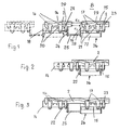
- the feed unit 8 (FIGS. 1 to 3) consists of two in the direction of travel 13 mutually adjustable feed elements 14 and 15, which are coupled together in the direction of travel 13, so that they simultaneously moved along the guide 7 together. ever according to the length of the wood to be processed 2, the two feed elements 14, 15 set at different distances from each other become.
- the machine has two feed units 8, 8 ', the lie on different sides of the guide 7 and both sides of Guides 3, 4 are arranged.
- the feed unit 8 ' is advantageous the same design as the feed unit 8 and has the two Feed elements 14 ', 15', which are relative to each other in the direction of travel 13 can be adjusted against each other.
- the two advancing elements 14, 15 are at the end at which the Woods 2 are to be processed frontally, each with a further, narrower jaw 22, 23 provided, with which also the woods 2 in the feed element 14, 15 can be clamped.
- the narrower clamping jaws 22, 23 are advantageously independent of the jaws 16, 17 height adjustable. But it is also possible the two jaws 22, 23 together with the jaws 16, 17 to be adjusted by a common lifting drive.
- the distance between the end face 28 of the cylinder 27 and the feed element 15 and the end face of the clamped on the advancing element 14 timber 2 is marked d 2 . These distances are chosen so that in the still to be described processing of the two woods 2 whose end faces can be edited with a corresponding tool. The distance d 1 , d 2 must thus be adjusted so that the corresponding processing tool can enter between the woods 2.
- Fig. 1 is a further feed element with dashed lines represented on which another wood can be clamped.
- the Another feed element is about a further adjustment with connected to the feed element 14, which is the same as the adjusting 26.
- the further feed element can be so adjust to the feed element 14 in the same way as the feed element 14 relative to the feed element 15. In the same way, further feed elements can be provided become.
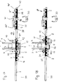
- Fig. 3 shows the possibility of the feed unit 8 for a very long time Woods 2 to edit.
- the length of the wood 2 larger than the entire length of the two feed elements 14, 15 is. Nevertheless, to reliably clamp the wood 2, the piston rod 15 of the adjusting device 26 is extended again. Now the long wood 2 with all the jaws 16, 22 and 17, 23 of the two feed elements 14, 15 clamped become.
- the feed elements 14, 15 be set at a fixed distance.
- the adjusting device 26 may also be designed so that the feed elements 14, 15 are set to variable distances can.
- the adjusting device 26 is then exemplified as CNC axis with motor-driven spindle-nut unit, as Servohydraulik- or designed as a servo-pneumatic cylinder.
- the feed unit 8 ' is of the same design as that described above Feed unit 8.
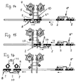
- the tool 5 is moved back with the carriage 9 along the guide 3 (FIG. 6). Then, the feed unit 8 'can be clocked so that now the front in the feed direction 13 end 36 of the feed element 14' clamped wood 2 in the working area of the tool 5 is (Fig. 7).
- the carriage 9 with the tool 5 is again moved in the transport direction 34, wherein the tool 5, the end face 36 of the on the advancing element 14 'located timber 2 edited.
- the distance d 1 or d 2 (FIG. 1) is set so that the tool 5 can move in without collision between the two woods 2 on the feed unit 8 '.
- the carriage 9 is moved back so far with the tool 5 (Fig. 8), that the feed unit 8 'counter to the feed direction 13 can be reduced.
- the carriage 10 with the tool 5 'in such Move position that left with him in the direction 13 Long sides 37, 38 of the woods 2 of the feed unit 8 'processed can be.
- This tool used for longitudinal profiling 5 'can in the area of the associated tool magazine 12 in the carriage 10 are replaced as long as the end faces 35, 36 of the woods 2 are processed in the manner described.
- the feed unit 8 ' In the feed direction 13 along the guide 7 method, the woods 2 at their in the feed direction 13 left longitudinal sides 37, 38 through the Tool 5 'are processed (Figs. 9 and 10).
- the other tool 5 on the carriage 9 is during the longitudinal side machining so far withdrawn that it does not hinder the advance of the unit 8 '.
- the feed unit 8 ' is moved so far until it the feed unit 8 opposite. She is on the other side of the leadership 7 arranged and can in the transfer position shown in Fig. 11 the partially processed woods 2 of the feed unit 8 'take over.
- the jaws 16, 17, 22, 23 are open, wherein the each lower support 18, 19 has been lowered for the woods 2, so that the woods 2, the 8 'while feeding the feed unit are clamped, get under the jaws of the feed unit 8 can.
- the clamping jaws 16, 17, 22, 23 at a small distance transversely to the guide 7 to the corresponding Jaws 16 ', 17', 22 ', 23' of the feed unit 8 '.
- the feed unit 8, the two feed elements 14, 15 in the same Way as the feed elements 14 ', 15' of the feed unit 8 ' Distance from each other, is then opposite feed direction 13 further along the guide 7 method (Figs. 14 and 15). in this connection the woods are 2 at their right in the feed direction 13 long side 29 processed with the tool 5 'on the carriage 10. The on the slide 9 located tool 5 has moved back so far that it does not come into contact with the woods 2.
- the woods 2 are on the advancing elements 14, 15 of the feed unit 8 tightened so that they counter to the feed direction 13 protrude over the feed elements 14 and 15. Of the Distance between the adjacent faces of the woods 2 on the two feed elements 14, 15 is set so that the tool 5 can dip between the two woods 2. The distance the end faces to be machined by the two tools 5, 5 ' 41, 42 of the two woods 2 corresponds to the distance between them both tools 5, 5 '.
- the carriage 9, 10 with the Tools 5, 5 'so far along the guides 3, 4 retracted, that processed with the tools 5, 5 ', the longitudinal sides 29 of the woods 2 can be.
- the feed unit 8 has previously moved so far been that they are on the same side of the processing unit 1 is like the feed unit 8 '. Subsequently, the Feed unit 8 in the feed direction 13 along the guide 7 method, wherein by the tools 5, 5 'in the feed direction 13th right longitudinal side 29 of the woods 2 is processed.
- the clamped on the feed unit 8 woods 2 are previously on their other front side and worked on their other long side Service.
- the woods 2 were initially on the feed unit 8 'tightened, which has been moved so far in the feed direction 13 is that with the tools 5, 5 ', the end faces 41, 42 of the woods. 2 could be processed simultaneously.
- the tools 5, 5 'are returned to the carriages 9, 10 and the feed unit 8 'against the feed direction 13 before moved the processing unit 1.
- the tools 5, 5 'are in drove such a situation that with them in the feed direction 13th left longitudinal sides 37, 38 of the woods 2 can be edited.
- this longitudinal side processing passes the feed unit 8 ' in the transfer position to the partially worked wood 2 in to pass the described manner of the feed unit 8.
- the feed unit 8 ' moves to its starting position back, while the feed unit 8 in the basis of Fig. 17 and 18 described way to the processing unit 1 driven is to the other end faces 41, 42 and the others Long sides 29 to edit.
- the Operator 30 on the feed unit in the starting position 8 ' clamp the next woods 2, so that immediately after the Processing the woods 2 on the feed unit 8 the new woods can be transported to the processing unit 1.
- feed unit 8 8 'four feed elements, then can the wood clamped in it with the two tools 5, 5 'in pairs be processed one after the other.
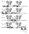
- FIGS. 19 to 27 a method will be described in which a machine with two processing units 1, 1 ', each with two Spindles is used.
- the handover of the woods 2 of the feed unit 8 'on the feed unit 8 takes place in this Trap in the area between the two processing units 1, 1 ' (Fig. 26).
- the feed unit 8 is then stopped when the rear end face 41 of the wood 2 on the advancing element 14 in the working area of the tool 5 ' the processing unit 1 is located.
- the feed unit 8 ' is stopped, when the front in the feed direction 13 front side 35th of the wood 2 on the feed element 15 in the working area of the Tool 5 'of the processing unit 1' is located.
- the two tools 5 'are with the carriage 10, 10' at the end faces 41, 35th passed, with the woods are processed on these front pages (Fig. 20).
- the carriage 9 is moved so far that the tool 5, the right in the feed direction 13 longitudinal side 29th the woods 2 of the feed unit 8 and the tool 5 'of the processing unit 1 'in the feed direction left longitudinal sides 37, 38 of the Woods 2 of the feed unit 8 'can edit.
- the two feed units 8, 8 ' are further in the feed direction 13 along the Guided run 7, the two tools 5, 5 'of the two Processing units 1, 1 ', the right and the left longitudinal side 29, 37, 38 of the woods 2 of the feed units 8, 8 'process (FIG. 23 and 24).
- the processing unit 1 'partially processed wood 2 on the Feed unit 8 are tightened, the jaws 16 ', 17 ', 22', 23 'raised in their release position and the pads 18, 19 lowered, so that the woods 2, already in the feed unit 8 are clamped, released.
- the Feed unit 8 now moves to the processing unit 1, in the the partially processed woods 2 in the reference to FIGS. 19 to 25 be processed described manner. Now begins a new one Duty cycle in which four woods in the same time described Be processed on their longitudinal and front sides. At both Machining units 1, 1 'is in each case also a simultaneous machining possible as described above.
Landscapes
- Engineering & Computer Science (AREA)
- Mechanical Engineering (AREA)
- Life Sciences & Earth Sciences (AREA)
- Wood Science & Technology (AREA)
- Forests & Forestry (AREA)
- Dovetailed Work, And Nailing Machines And Stapling Machines For Wood (AREA)
- Turning (AREA)
- Multi-Process Working Machines And Systems (AREA)
- Constituent Portions Of Griding Lathes, Driving, Sensing And Control (AREA)
- Pressure Welding/Diffusion-Bonding (AREA)
- Electrical Discharge Machining, Electrochemical Machining, And Combined Machining (AREA)
- Veneer Processing And Manufacture Of Plywood (AREA)
- Feeding Of Workpieces (AREA)
Abstract
Description
- Fig. 1
- in schematischer Darstellung eine Vorschubeinheit einer erfindungsgemäßen Bearbeitungsmaschine,
- Fig. 2 und Fig. 3
- die Vorschubeinheit gemäß Fig. 1 in unterschiedlichen Stellungen zur Aufnahme unterschiedlich langer Werkstücke,
- Fig. 4 bis Fig. 16
- verschiedene Verfahrensschritte bei der Bearbeitung von Werkstücken auf der erfindungsgemäßen Bearbeitungsmaschine,
- Fig. 17 und Fig. 18
- eine Simultanbearbeitung auf der erfindungsgemäßen Bearbeitungsmaschine,
- Fig. 19 bis Fig. 27
- eine Bearbeitung von Werkstücken auf einer zweiten Ausführungsform einer erfindungsgemäßen Bearbeitungsmaschine.
Claims (25)
- Vorschubeinheit für eine Maschine zum Bearbeiten von Werkstücken aus Holz, Kunststoff oder dergleichen, mit wenigstens einer Klemmeinrichtung zum Festspannen der Werkstücke, dadurch gekennzeichnet, daß die Vorschubeinheit (8, 8') wenigstens zwei Vorschubelemente (14, 15; 14', 15') aufweist, deren Abstand relativ zueinander in Vorschubrichtung (13) einstellbar ist.
- Vorschubeinheit nach Anspruch 1,
dadurch gekennzeichnet, daß die Vorschubelemente (14, 15; 14', 15') jeweils eine Klemmeinrichtung (16, 17, 22; 16', 17', 23) für die Werkstücke (2) aufweisen. - Vorschubeinheit nach Anspruch 1 oder 2,
dadurch gekennzeichnet, daß die beiden Vorschubelemente (14, 15; 14', 15') durch eine Verstelleinrichtung (26, 26') miteinander verbunden sind. - Vorschubeinheit nach Anspruch 3,
dadurch gekennzeichnet, daß die Verstelleinrichtung (26, 26') wenigstens eine Kolben-Zylinder-Einheit aufweist. - Vorschubeinheit nach Anspruch 4,
dadurch gekennzeichnet, daß die Kolben-Zylinder-Einheit eine Kolbenstange (25) aufweist, die mit dem einen Vorschubelement (14, 14') gekoppelt ist. - Vorschubeinheit nach Anspruch 4 oder 5,
dadurch gekennzeichnet, daß der Zylinder (27) der Kolben-Zylinder-Einheit am anderen Vorschubelement (15, 15') vorgesehen ist. - Vorschubeinheit nach einem der Ansprüche 1 bis 6,
dadurch gekennzeichnet, daß die Vorschubelemente (14, 15; 14', 15') als Einheit verfahrbar sind. - Verfahren zum Bearbeiten von Werkstücken aus Holz, Kunststoff und dergleichen, bei dem die Werkstücke an zumindest einer Stirnseite und/oder Längsseite durch wenigstens ein Werkzeug bearbeitet werden, unter Verwendung der Vorschubeinheit nach einem der Ansprüche 1 bis 7,
dadurch gekennzeichnet, daß in der Vorschubeinheit (8, 8') wenigstens zwei Werkstücke (2) so eingespannt werden, daß sie mit einem Ende über das jeweilige Vorschubelement (14, 15; 14', 15') ragen. - Verfahren nach Anspruch 8,
dadurch gekennzeichnet, daß die beiden Vorschubelemente (14, 15; 14', 15') der Vorschubeinheit (8, 8') so relativ zueinander in Vorschubrichtung (13) eingestellt werden, daß zwischen die beiden Werkstücke (2) auf den Vorschubelementen (14, 15; 14', 15') das Werkzeug (5, 5') zur Bearbeitung der Stirnseiten (35, 36; 41, 42) der Werkstücke (2) einfahren kann. - Verfahren, insbesondere nach Anspruch 8 oder 9,
dadurch gekennzeichnet, daß die Werkstücke (2) auf der Vorschubeinheit (8) zunächst an einer Stirnseite (35, 36) und/oder an einer Längsseite (37, 38) bearbeitet und anschließend an eine weitere Vorschubeinheit (8') übergeben werden, auf der die andere Stirnseite (41, 42) und/oder die andere Längsseite (29) der Werkstücke (2) bearbeitet werden. - Verfahren, insbesondere nach einem der Ansprüche 8 bis 10,
dadurch gekennzeichnet, daß gleichzeitig mehrere Werkstücke (2) bearbeitet werden, die auf wenigstens zwei Vorschubelementen (14, 15) eingespannt sind. - Verfahren nach Anspruch 11,
dadurch gekennzeichnet, daß die Werkstücke (2) auf den Vorschubeinheiten (8, 8') teilweise bearbeitet werden, und daß die teilweise bearbeiteten Werkstücke (2) anschließend von der einen Vorschubeinheit (8) der anderen Vorschubeinheit (8') übergeben werden. - Verfahren nach Anspruch 11 oder 12,
dadurch gekennzeichnet, daß die beiden Vorschubeinheiten (8, 8') gleich ausgebildet sind. - Verfahren nach einem der Ansprüche 11 bis 13,
dadurch gekennzeichnet, daß die Übergabe der Werkstücke zwischen den Vorschubeinheiten (8, 8') im Bereich zwischen zwei Bearbeitungseinheiten (1, 1') vorgenommen wird. - Verfahren nach einem der Ansprüche 11 bis 14,
dadurch gekennzeichnet, daß auf den Vorschubeinheiten (8, 8') jeweils zwei Werkstücke (2) eingespannt werden. - Verfahren nach einem der Ansprüche 11 bis 15,
dadurch gekennzeichnet, daß die Stirnseiten (35, 41; 36, 42) der Werkstücke (2) jeweils paarweise gleichzeitig bearbeitet werden. - Verfahren nach einem der Ansprüche 11 bis 16,
dadurch gekennzeichnet, daß die einen Längsseiten (29, 37, 38) der Werkstücke (2) jeweils paarweise gleichzeitig bearbeitet werden. - Verfahren nach einem der Ansprüche 11 bis 17,
dadurch gekennzeichnet, daß nach der Übergabe der Werkstükke (2) von der einen an die andere Vorschubeinheit (8, 8') die anderen Längsseiten und Stirnseiten der Werkstücke (2) jeweils paarweise gleichzeitig bearbeitet werden. - Verfahren, insbesondere nach einem der Ansprüche 8 bis 18,
dadurch gekennzeichnet, daß die Werkstücke (2) bei der Übergabe zwischen den Vorschubeinheiten (8, 8') stets eingespannt bleiben. - Verfahren nach einem der Ansprüche 8 bis 19,
dadurch gekennzeichnet, daß die Werkstücke (2) bei der Bearbeitung der Längsseite an wenigstens einem Bohraggregat gebohrt werden. - Verfahren nach einem der Ansprüche 8 bis 20,
dadurch gekennzeichnet, daß als Vorschubeinheit (8, 8') eine Spanneinheit verwendet wird. - Verfahren nach einem der Ansprüche 8 bis 21,
dadurch gekennzeichnet, daß die Werkstücke (2) zwischen oberen und unteren Klemmbacken (16, 17, 18, 19) eingespannt werden. - Verfahren nach Anspruch 22,
dadurch gekennzeichnet, daß zumindest ein Teil der oberen Klemmbacken (16, 17) der Vorschubeinheit (8, 8') mit einem Antrieb verstellt wird. - Verfahren nach Anspruch 22 oder 23,
dadurch gekennzeichnet, daß die oberen Klemmbacken (16, 17) einzeln verstellbar sind. - Verfahren, insbesondere nach einem der Ansprüche 22 bis 24,
dadurch gekennzeichnet, daß die oberen Klemmbacken (16, 17) Lücken (20, 21) zwischen den unteren Klemmbacken (18, 19) gegenüberliegen.
Applications Claiming Priority (2)
| Application Number | Priority Date | Filing Date | Title |
|---|---|---|---|
| DE102004027888A DE102004027888B4 (de) | 2004-05-27 | 2004-05-27 | Vorschubeinheit für eine Maschine zum Bearbeiten von Werkstücken aus Holz, Kunststoff oder dergleichen sowie Verfahren zum Bearbeiten solcher Werkstücke |
| DE102004027888 | 2004-05-27 |
Publications (2)
| Publication Number | Publication Date |
|---|---|
| EP1600254A1 true EP1600254A1 (de) | 2005-11-30 |
| EP1600254B1 EP1600254B1 (de) | 2007-10-10 |
Family
ID=34936475
Family Applications (1)
| Application Number | Title | Priority Date | Filing Date |
|---|---|---|---|
| EP05010415A Expired - Lifetime EP1600254B1 (de) | 2004-05-27 | 2005-05-13 | Vorschubeinheit für eine Maschine zum Bearbeiten von Werkstücken sowie Verfahren zum Bearbeiten solcher Werkstücke |
Country Status (5)
| Country | Link |
|---|---|
| EP (1) | EP1600254B1 (de) |
| CN (1) | CN1701915B (de) |
| AT (1) | ATE375225T1 (de) |
| DE (2) | DE102004027888B4 (de) |
| TW (1) | TW200603937A (de) |
Cited By (9)
| Publication number | Priority date | Publication date | Assignee | Title |
|---|---|---|---|---|
| EP1810802A1 (de) | 2006-01-20 | 2007-07-25 | SCM GROUP S.p.A. | Werkzeugmaschine |
| EP1832402A1 (de) * | 2006-03-10 | 2007-09-12 | IMPRESA 2000 DI SACCHI PARIDE E C. s.a.s. | Formmaschine zum Formen von Bestandteilen aus Holz oder dergleichen in Längsrichtung, insbesondere für Bestandteile von Tür- oder Fensterrahmen |
| WO2009030348A1 (de) * | 2007-08-28 | 2009-03-12 | Michael Weinig Ag | Vorrichtung zur bearbeitung von werkstücken aus holz, kunststoff und dergleichen sowie verfahren zum bearbeiten von solchen werkstücken |
| ITBO20090640A1 (it) * | 2009-10-02 | 2011-04-03 | Biesse Spa | Metodo e macchina per la lavorazione di componenti di legno o simili per infissi |
| ITFI20130097A1 (it) * | 2013-05-03 | 2014-11-04 | Paolino Bacci Srl | "centro di lavoro" |
| WO2016071337A1 (de) * | 2014-11-03 | 2016-05-12 | Homag Holzbearbeitungssysteme Gmbh | Bearbeitungsvorrichtung für werkstücke und verfahren hierfür |
| WO2017055111A1 (de) * | 2015-09-29 | 2017-04-06 | Homag Gmbh | Bearbeitungsvorrichtung |
| EP2998065B1 (de) * | 2014-09-22 | 2019-11-06 | HOMAG GmbH | Bearbeitungsvorrichtung mit einem werkstücktisch |
| CN115592474A (zh) * | 2022-12-16 | 2023-01-13 | 朗快智能科技(杭州)有限公司(Cn) | 一种多工位加工设备及加工方法 |
Families Citing this family (6)
| Publication number | Priority date | Publication date | Assignee | Title |
|---|---|---|---|---|
| EP1882570B2 (de) * | 2006-07-25 | 2012-09-19 | Homag Holzbearbeitungssysteme AG | Bearbeitungszentrum zur Bearbeitung lang gestreckter Werkstücke |
| DE202010000935U1 (de) | 2010-01-14 | 2010-03-25 | Homag Holzbearbeitungssysteme Ag | Vorrichtung zum Bearbeiten von Werkstücken |
| DE102016009430A1 (de) * | 2016-07-29 | 2018-02-01 | Michael Weinig Ag | Anlage und Verfahren zum Bearbeiten von Werkstücken aus Holz, Kunststoff und dergleichen |
| DE102016117055A1 (de) | 2016-09-12 | 2018-03-15 | Homag Plattenaufteiltechnik Gmbh | Plattenaufteilanlage |
| DE102019003613A1 (de) * | 2019-05-21 | 2020-11-26 | Michael Weinig Ag | Verfahren zur Bearbeitung von Werkstücken aus Holz, Kunststoff und dergleichen |
| CN118358988A (zh) * | 2023-01-19 | 2024-07-19 | 佛山市艾乐博机器人股份有限公司 | 物料搬运系统 |
Citations (3)
| Publication number | Priority date | Publication date | Assignee | Title |
|---|---|---|---|---|
| JPS58114837A (ja) * | 1981-12-25 | 1983-07-08 | Takahata Tokio | 加工物搬送装置 |
| US20030024363A1 (en) * | 2001-08-02 | 2003-02-06 | Michael Weinig Aktiengesellschaft | Machine and method for machining workpieces of wood, plastic material or the like |
| EP1304188A2 (de) * | 2001-10-19 | 2003-04-23 | IMPRESA 2000 DI SACCHI PARIDE E C. s.a.s. | Verfahren und Maschine zur Bearbeitung von Holzteilen oder dergleichen |
Family Cites Families (4)
| Publication number | Priority date | Publication date | Assignee | Title |
|---|---|---|---|---|
| DE4425487A1 (de) * | 1993-07-21 | 1995-04-06 | Koike Sanso Kogyo Kk | Rahmengestellaufbau und damit versehene Bearbeitungseinrichtung |
| CN2211342Y (zh) * | 1994-09-04 | 1995-11-01 | 信阳木工机械厂 | 成型木线条压刨床 |
| DE19514058C2 (de) * | 1995-04-13 | 1998-04-30 | Emag Masch Vertriebs Serv Gmbh | Drehmaschine mit mehreren Spindeln |
| ES2146140B1 (es) * | 1996-10-15 | 2001-04-01 | Torres Martinez M | Maquina para el soporte y mecanizado de piezas. |
-
2004
- 2004-05-27 DE DE102004027888A patent/DE102004027888B4/de not_active Expired - Fee Related
-
2005
- 2005-05-11 TW TW094115156A patent/TW200603937A/zh not_active IP Right Cessation
- 2005-05-13 DE DE502005001646T patent/DE502005001646D1/de not_active Expired - Lifetime
- 2005-05-13 AT AT05010415T patent/ATE375225T1/de active
- 2005-05-13 EP EP05010415A patent/EP1600254B1/de not_active Expired - Lifetime
- 2005-05-27 CN CN200510071360.1A patent/CN1701915B/zh not_active Expired - Fee Related
Patent Citations (3)
| Publication number | Priority date | Publication date | Assignee | Title |
|---|---|---|---|---|
| JPS58114837A (ja) * | 1981-12-25 | 1983-07-08 | Takahata Tokio | 加工物搬送装置 |
| US20030024363A1 (en) * | 2001-08-02 | 2003-02-06 | Michael Weinig Aktiengesellschaft | Machine and method for machining workpieces of wood, plastic material or the like |
| EP1304188A2 (de) * | 2001-10-19 | 2003-04-23 | IMPRESA 2000 DI SACCHI PARIDE E C. s.a.s. | Verfahren und Maschine zur Bearbeitung von Holzteilen oder dergleichen |
Non-Patent Citations (1)
| Title |
|---|
| PATENT ABSTRACTS OF JAPAN vol. 007, no. 221 (M - 246) 30 September 1983 (1983-09-30) * |
Cited By (12)
| Publication number | Priority date | Publication date | Assignee | Title |
|---|---|---|---|---|
| EP1810802A1 (de) | 2006-01-20 | 2007-07-25 | SCM GROUP S.p.A. | Werkzeugmaschine |
| EP1832402A1 (de) * | 2006-03-10 | 2007-09-12 | IMPRESA 2000 DI SACCHI PARIDE E C. s.a.s. | Formmaschine zum Formen von Bestandteilen aus Holz oder dergleichen in Längsrichtung, insbesondere für Bestandteile von Tür- oder Fensterrahmen |
| WO2009030348A1 (de) * | 2007-08-28 | 2009-03-12 | Michael Weinig Ag | Vorrichtung zur bearbeitung von werkstücken aus holz, kunststoff und dergleichen sowie verfahren zum bearbeiten von solchen werkstücken |
| ITBO20090640A1 (it) * | 2009-10-02 | 2011-04-03 | Biesse Spa | Metodo e macchina per la lavorazione di componenti di legno o simili per infissi |
| EP2305440A1 (de) * | 2009-10-02 | 2011-04-06 | BIESSE S.p.A. | Verfahren und Vorrichtung zur Verarbeitung von Bauteilen aus Holz und dergleichen |
| ITFI20130097A1 (it) * | 2013-05-03 | 2014-11-04 | Paolino Bacci Srl | "centro di lavoro" |
| WO2014177997A1 (en) * | 2013-05-03 | 2014-11-06 | Paolino Bacci S.R.L. | Machining center |
| EP2998065B1 (de) * | 2014-09-22 | 2019-11-06 | HOMAG GmbH | Bearbeitungsvorrichtung mit einem werkstücktisch |
| WO2016071337A1 (de) * | 2014-11-03 | 2016-05-12 | Homag Holzbearbeitungssysteme Gmbh | Bearbeitungsvorrichtung für werkstücke und verfahren hierfür |
| WO2017055111A1 (de) * | 2015-09-29 | 2017-04-06 | Homag Gmbh | Bearbeitungsvorrichtung |
| US10940607B2 (en) | 2015-09-29 | 2021-03-09 | Homag Gmbh | Machining device |
| CN115592474A (zh) * | 2022-12-16 | 2023-01-13 | 朗快智能科技(杭州)有限公司(Cn) | 一种多工位加工设备及加工方法 |
Also Published As
| Publication number | Publication date |
|---|---|
| CN1701915B (zh) | 2011-01-05 |
| DE502005001646D1 (de) | 2007-11-22 |
| TWI293264B (de) | 2008-02-11 |
| CN1701915A (zh) | 2005-11-30 |
| ATE375225T1 (de) | 2007-10-15 |
| TW200603937A (en) | 2006-02-01 |
| EP1600254B1 (de) | 2007-10-10 |
| DE102004027888B4 (de) | 2007-01-04 |
| DE102004027888A1 (de) | 2005-12-22 |
Similar Documents
| Publication | Publication Date | Title |
|---|---|---|
| EP1281491B1 (de) | Maschine und Verfahren zum Bearbeiten von Werkstücken aus Holz, Kunststoff oder dergleichen | |
| EP0922547B1 (de) | Maschine zum Bearbeiten von Fensterrahmen-Holmen | |
| DE3511498C2 (de) | Vorrichtung zur Bearbeitung von Pfosten oder Sprossen aus Kunststoff- oder Aluminium-Profilstäben für Fenster oder Türen | |
| EP1600254B1 (de) | Vorschubeinheit für eine Maschine zum Bearbeiten von Werkstücken sowie Verfahren zum Bearbeiten solcher Werkstücke | |
| EP3197639A1 (de) | Bearbeitungsvorrichtung | |
| EP0130309A1 (de) | Holzbearbeitungsmaschinen | |
| DE102008048553A1 (de) | Maschine und Verfahren zur Bearbeitung von Werkstücken aus Holz, Kunststoff und dergleichen | |
| DE4116769C2 (de) | Doppelgehrungssäge | |
| DE2312376C2 (de) | Aufteilsägemaschine | |
| EP2185331B1 (de) | Vorrichtung zur bearbeitung von werkstücken aus holz, kunststoff und dergleichen sowie verfahren zum bearbeiten von solchen werkstücken | |
| DE3307809A1 (de) | Holzbearbeitungsmaschine | |
| EP0292864B1 (de) | Holzbearbeitungsmaschine | |
| EP0561227A1 (de) | Abbundmaschine zum Bearbeiten von Kanthölzern oder dergleichen | |
| EP0623420B1 (de) | Transport- und Haltevorrichtung | |
| AT514168A1 (de) | Vorrichtung zur Herstellung eines Stranges | |
| DE10033705C2 (de) | Vorrichtung zum Bearbeiten von langgestreckten Werkstücken, insbesondere von Fenster- und Türeneinzelteilen | |
| DE9315813U1 (de) | Langbettmaschine zur Bearbeitung von Profilen | |
| DE102006009421A1 (de) | Kehlmaschine | |
| DE19703240B4 (de) | Vorrichtung zum Handhaben und Bearbeiten von vorzugsweise plattenförmigen Werkstücken | |
| DE3042716C2 (de) | Werkstückpositioniervorrichtung | |
| DE3717411C2 (de) | ||
| DE19721521C2 (de) | Numerisch gesteuerte Zapfenschneidmaschine | |
| WO2011095572A1 (de) | Werkzeugmaschine zum bearbeiten von schlanken werkstücken | |
| DE10212216B4 (de) | Bearbeitungszentrum mit Bearbeitungseinheit und Versorgungseinheit | |
| DE1453268A1 (de) | Keilzinkenfraesmaschine |
Legal Events
| Date | Code | Title | Description |
|---|---|---|---|
| PUAI | Public reference made under article 153(3) epc to a published international application that has entered the european phase |
Free format text: ORIGINAL CODE: 0009012 |
|
| AK | Designated contracting states |
Kind code of ref document: A1 Designated state(s): AT BE BG CH CY CZ DE DK EE ES FI FR GB GR HU IE IS IT LI LT LU MC NL PL PT RO SE SI SK TR |
|
| AX | Request for extension of the european patent |
Extension state: AL BA HR LV MK YU |
|
| 17P | Request for examination filed |
Effective date: 20060508 |
|
| AKX | Designation fees paid |
Designated state(s): AT BE BG CH CY CZ DE DK EE ES FI FR GB GR HU IE IS IT LI LT LU MC NL PL PT RO SE SI SK TR |
|
| 17Q | First examination report despatched |
Effective date: 20061019 |
|
| GRAP | Despatch of communication of intention to grant a patent |
Free format text: ORIGINAL CODE: EPIDOSNIGR1 |
|
| GRAS | Grant fee paid |
Free format text: ORIGINAL CODE: EPIDOSNIGR3 |
|
| GRAA | (expected) grant |
Free format text: ORIGINAL CODE: 0009210 |
|
| AK | Designated contracting states |
Kind code of ref document: B1 Designated state(s): AT BE BG CH CY CZ DE DK EE ES FI FR GB GR HU IE IS IT LI LT LU MC NL PL PT RO SE SI SK TR |
|
| REG | Reference to a national code |
Ref country code: GB Ref legal event code: FG4D Free format text: NOT ENGLISH |
|
| REG | Reference to a national code |
Ref country code: CH Ref legal event code: EP |
|
| REG | Reference to a national code |
Ref country code: IE Ref legal event code: FG4D Free format text: LANGUAGE OF EP DOCUMENT: GERMAN |
|
| REF | Corresponds to: |
Ref document number: 502005001646 Country of ref document: DE Date of ref document: 20071122 Kind code of ref document: P |
|
| GBT | Gb: translation of ep patent filed (gb section 77(6)(a)/1977) |
Effective date: 20080122 |
|
| ET | Fr: translation filed | ||
| PG25 | Lapsed in a contracting state [announced via postgrant information from national office to epo] |
Ref country code: SE Free format text: LAPSE BECAUSE OF FAILURE TO SUBMIT A TRANSLATION OF THE DESCRIPTION OR TO PAY THE FEE WITHIN THE PRESCRIBED TIME-LIMIT Effective date: 20080110 Ref country code: ES Free format text: LAPSE BECAUSE OF FAILURE TO SUBMIT A TRANSLATION OF THE DESCRIPTION OR TO PAY THE FEE WITHIN THE PRESCRIBED TIME-LIMIT Effective date: 20080121 |
|
| PG25 | Lapsed in a contracting state [announced via postgrant information from national office to epo] |
Ref country code: PL Free format text: LAPSE BECAUSE OF FAILURE TO SUBMIT A TRANSLATION OF THE DESCRIPTION OR TO PAY THE FEE WITHIN THE PRESCRIBED TIME-LIMIT Effective date: 20071010 Ref country code: LT Free format text: LAPSE BECAUSE OF FAILURE TO SUBMIT A TRANSLATION OF THE DESCRIPTION OR TO PAY THE FEE WITHIN THE PRESCRIBED TIME-LIMIT Effective date: 20071010 Ref country code: BG Free format text: LAPSE BECAUSE OF FAILURE TO SUBMIT A TRANSLATION OF THE DESCRIPTION OR TO PAY THE FEE WITHIN THE PRESCRIBED TIME-LIMIT Effective date: 20080110 Ref country code: IS Free format text: LAPSE BECAUSE OF FAILURE TO SUBMIT A TRANSLATION OF THE DESCRIPTION OR TO PAY THE FEE WITHIN THE PRESCRIBED TIME-LIMIT Effective date: 20080210 Ref country code: PT Free format text: LAPSE BECAUSE OF FAILURE TO SUBMIT A TRANSLATION OF THE DESCRIPTION OR TO PAY THE FEE WITHIN THE PRESCRIBED TIME-LIMIT Effective date: 20080310 |
|
| REG | Reference to a national code |
Ref country code: IE Ref legal event code: FD4D |
|
| PG25 | Lapsed in a contracting state [announced via postgrant information from national office to epo] |
Ref country code: DK Free format text: LAPSE BECAUSE OF FAILURE TO SUBMIT A TRANSLATION OF THE DESCRIPTION OR TO PAY THE FEE WITHIN THE PRESCRIBED TIME-LIMIT Effective date: 20071010 Ref country code: CZ Free format text: LAPSE BECAUSE OF FAILURE TO SUBMIT A TRANSLATION OF THE DESCRIPTION OR TO PAY THE FEE WITHIN THE PRESCRIBED TIME-LIMIT Effective date: 20071010 |
|
| PLBE | No opposition filed within time limit |
Free format text: ORIGINAL CODE: 0009261 |
|
| STAA | Information on the status of an ep patent application or granted ep patent |
Free format text: STATUS: NO OPPOSITION FILED WITHIN TIME LIMIT |
|
| PG25 | Lapsed in a contracting state [announced via postgrant information from national office to epo] |
Ref country code: SK Free format text: LAPSE BECAUSE OF FAILURE TO SUBMIT A TRANSLATION OF THE DESCRIPTION OR TO PAY THE FEE WITHIN THE PRESCRIBED TIME-LIMIT Effective date: 20071010 Ref country code: RO Free format text: LAPSE BECAUSE OF FAILURE TO SUBMIT A TRANSLATION OF THE DESCRIPTION OR TO PAY THE FEE WITHIN THE PRESCRIBED TIME-LIMIT Effective date: 20071010 |
|
| 26N | No opposition filed |
Effective date: 20080711 |
|
| PG25 | Lapsed in a contracting state [announced via postgrant information from national office to epo] |
Ref country code: IE Free format text: LAPSE BECAUSE OF FAILURE TO SUBMIT A TRANSLATION OF THE DESCRIPTION OR TO PAY THE FEE WITHIN THE PRESCRIBED TIME-LIMIT Effective date: 20071010 |
|
| BERE | Be: lapsed |
Owner name: MICHAEL WEINIG A.G. Effective date: 20080531 |
|
| PG25 | Lapsed in a contracting state [announced via postgrant information from national office to epo] |
Ref country code: MC Free format text: LAPSE BECAUSE OF NON-PAYMENT OF DUE FEES Effective date: 20080531 |
|
| PG25 | Lapsed in a contracting state [announced via postgrant information from national office to epo] |
Ref country code: EE Free format text: LAPSE BECAUSE OF FAILURE TO SUBMIT A TRANSLATION OF THE DESCRIPTION OR TO PAY THE FEE WITHIN THE PRESCRIBED TIME-LIMIT Effective date: 20071010 Ref country code: GR Free format text: LAPSE BECAUSE OF FAILURE TO SUBMIT A TRANSLATION OF THE DESCRIPTION OR TO PAY THE FEE WITHIN THE PRESCRIBED TIME-LIMIT Effective date: 20080111 |
|
| PG25 | Lapsed in a contracting state [announced via postgrant information from national office to epo] |
Ref country code: FI Free format text: LAPSE BECAUSE OF FAILURE TO SUBMIT A TRANSLATION OF THE DESCRIPTION OR TO PAY THE FEE WITHIN THE PRESCRIBED TIME-LIMIT Effective date: 20071010 |
|
| PG25 | Lapsed in a contracting state [announced via postgrant information from national office to epo] |
Ref country code: BE Free format text: LAPSE BECAUSE OF NON-PAYMENT OF DUE FEES Effective date: 20080531 |
|
| PG25 | Lapsed in a contracting state [announced via postgrant information from national office to epo] |
Ref country code: SI Free format text: LAPSE BECAUSE OF FAILURE TO SUBMIT A TRANSLATION OF THE DESCRIPTION OR TO PAY THE FEE WITHIN THE PRESCRIBED TIME-LIMIT Effective date: 20071010 |
|
| PG25 | Lapsed in a contracting state [announced via postgrant information from national office to epo] |
Ref country code: CY Free format text: LAPSE BECAUSE OF FAILURE TO SUBMIT A TRANSLATION OF THE DESCRIPTION OR TO PAY THE FEE WITHIN THE PRESCRIBED TIME-LIMIT Effective date: 20071010 |
|
| REG | Reference to a national code |
Ref country code: CH Ref legal event code: PL |
|
| PG25 | Lapsed in a contracting state [announced via postgrant information from national office to epo] |
Ref country code: CH Free format text: LAPSE BECAUSE OF NON-PAYMENT OF DUE FEES Effective date: 20090531 Ref country code: LI Free format text: LAPSE BECAUSE OF NON-PAYMENT OF DUE FEES Effective date: 20090531 |
|
| PG25 | Lapsed in a contracting state [announced via postgrant information from national office to epo] |
Ref country code: LU Free format text: LAPSE BECAUSE OF NON-PAYMENT OF DUE FEES Effective date: 20080513 Ref country code: HU Free format text: LAPSE BECAUSE OF FAILURE TO SUBMIT A TRANSLATION OF THE DESCRIPTION OR TO PAY THE FEE WITHIN THE PRESCRIBED TIME-LIMIT Effective date: 20080411 |
|
| PG25 | Lapsed in a contracting state [announced via postgrant information from national office to epo] |
Ref country code: IT Free format text: LAPSE BECAUSE OF NON-PAYMENT OF DUE FEES Effective date: 20100513 |
|
| PGRI | Patent reinstated in contracting state [announced from national office to epo] |
Ref country code: IT Effective date: 20110616 |
|
| REG | Reference to a national code |
Ref country code: FR Ref legal event code: PLFP Year of fee payment: 12 |
|
| REG | Reference to a national code |
Ref country code: FR Ref legal event code: PLFP Year of fee payment: 13 |
|
| REG | Reference to a national code |
Ref country code: FR Ref legal event code: PLFP Year of fee payment: 14 |
|
| PGFP | Annual fee paid to national office [announced via postgrant information from national office to epo] |
Ref country code: FR Payment date: 20200504 Year of fee payment: 16 Ref country code: NL Payment date: 20200525 Year of fee payment: 16 Ref country code: TR Payment date: 20200508 Year of fee payment: 16 |
|
| PGFP | Annual fee paid to national office [announced via postgrant information from national office to epo] |
Ref country code: IT Payment date: 20200529 Year of fee payment: 16 Ref country code: GB Payment date: 20200513 Year of fee payment: 16 |
|
| PGFP | Annual fee paid to national office [announced via postgrant information from national office to epo] |
Ref country code: AT Payment date: 20200513 Year of fee payment: 16 |
|
| REG | Reference to a national code |
Ref country code: NL Ref legal event code: MM Effective date: 20210601 |
|
| REG | Reference to a national code |
Ref country code: AT Ref legal event code: MM01 Ref document number: 375225 Country of ref document: AT Kind code of ref document: T Effective date: 20210513 |
|
| GBPC | Gb: european patent ceased through non-payment of renewal fee |
Effective date: 20210513 |
|
| PG25 | Lapsed in a contracting state [announced via postgrant information from national office to epo] |
Ref country code: AT Free format text: LAPSE BECAUSE OF NON-PAYMENT OF DUE FEES Effective date: 20210513 |
|
| PG25 | Lapsed in a contracting state [announced via postgrant information from national office to epo] |
Ref country code: GB Free format text: LAPSE BECAUSE OF NON-PAYMENT OF DUE FEES Effective date: 20210513 |
|
| PG25 | Lapsed in a contracting state [announced via postgrant information from national office to epo] |
Ref country code: NL Free format text: LAPSE BECAUSE OF NON-PAYMENT OF DUE FEES Effective date: 20210601 Ref country code: FR Free format text: LAPSE BECAUSE OF NON-PAYMENT OF DUE FEES Effective date: 20210531 |
|
| PGFP | Annual fee paid to national office [announced via postgrant information from national office to epo] |
Ref country code: DE Payment date: 20220726 Year of fee payment: 18 |
|
| PG25 | Lapsed in a contracting state [announced via postgrant information from national office to epo] |
Ref country code: IT Free format text: LAPSE BECAUSE OF NON-PAYMENT OF DUE FEES Effective date: 20210531 |
|
| REG | Reference to a national code |
Ref country code: DE Ref legal event code: R119 Ref document number: 502005001646 Country of ref document: DE |
|
| PG25 | Lapsed in a contracting state [announced via postgrant information from national office to epo] |
Ref country code: DE Free format text: LAPSE BECAUSE OF NON-PAYMENT OF DUE FEES Effective date: 20231201 |