EP1600225A1 - Stanzmaschine mit elektrischem Dreh-/Hubantrieb - Google Patents
Stanzmaschine mit elektrischem Dreh-/Hubantrieb Download PDFInfo
- Publication number
- EP1600225A1 EP1600225A1 EP04012523A EP04012523A EP1600225A1 EP 1600225 A1 EP1600225 A1 EP 1600225A1 EP 04012523 A EP04012523 A EP 04012523A EP 04012523 A EP04012523 A EP 04012523A EP 1600225 A1 EP1600225 A1 EP 1600225A1
- Authority
- EP
- European Patent Office
- Prior art keywords
- spindle
- rotary
- drive
- lifting
- drive motor
- Prior art date
- Legal status (The legal status is an assumption and is not a legal conclusion. Google has not performed a legal analysis and makes no representation as to the accuracy of the status listed.)
- Granted
Links
- 238000004080 punching Methods 0.000 title claims description 42
- 238000003860 storage Methods 0.000 claims description 34
- 230000008878 coupling Effects 0.000 claims description 11
- 238000010168 coupling process Methods 0.000 claims description 11
- 238000005859 coupling reaction Methods 0.000 claims description 11
- 238000006073 displacement reaction Methods 0.000 claims description 11
- 238000000926 separation method Methods 0.000 claims description 4
- 238000001514 detection method Methods 0.000 description 7
- 238000003754 machining Methods 0.000 description 5
- 101100390736 Danio rerio fign gene Proteins 0.000 description 2
- 101100390738 Mus musculus Fign gene Proteins 0.000 description 2
- 238000010276 construction Methods 0.000 description 2
- 238000005096 rolling process Methods 0.000 description 2
- 241000549194 Euonymus europaeus Species 0.000 description 1
- 230000001419 dependent effect Effects 0.000 description 1
- 230000009977 dual effect Effects 0.000 description 1
- 210000003746 feather Anatomy 0.000 description 1
- 238000009434 installation Methods 0.000 description 1
- 238000004519 manufacturing process Methods 0.000 description 1
- 239000002184 metal Substances 0.000 description 1
- 210000003800 pharynx Anatomy 0.000 description 1
- 230000002441 reversible effect Effects 0.000 description 1
Images


Classifications
-
- B—PERFORMING OPERATIONS; TRANSPORTING
- B21—MECHANICAL METAL-WORKING WITHOUT ESSENTIALLY REMOVING MATERIAL; PUNCHING METAL
- B21D—WORKING OR PROCESSING OF SHEET METAL OR METAL TUBES, RODS OR PROFILES WITHOUT ESSENTIALLY REMOVING MATERIAL; PUNCHING METAL
- B21D28/00—Shaping by press-cutting; Perforating
- B21D28/002—Drive of the tools
-
- Y—GENERAL TAGGING OF NEW TECHNOLOGICAL DEVELOPMENTS; GENERAL TAGGING OF CROSS-SECTIONAL TECHNOLOGIES SPANNING OVER SEVERAL SECTIONS OF THE IPC; TECHNICAL SUBJECTS COVERED BY FORMER USPC CROSS-REFERENCE ART COLLECTIONS [XRACs] AND DIGESTS
- Y10—TECHNICAL SUBJECTS COVERED BY FORMER USPC
- Y10T—TECHNICAL SUBJECTS COVERED BY FORMER US CLASSIFICATION
- Y10T483/00—Tool changing
- Y10T483/17—Tool changing including machine tool or component
- Y10T483/1733—Rotary spindle machine tool [e.g., milling machine, boring, machine, grinding machine, etc.]
- Y10T483/179—Direct tool exchange between spindle and matrix
- Y10T483/1793—Spindle comprises tool changer
- Y10T483/1795—Matrix indexes selected tool to transfer position
-
- Y—GENERAL TAGGING OF NEW TECHNOLOGICAL DEVELOPMENTS; GENERAL TAGGING OF CROSS-SECTIONAL TECHNOLOGIES SPANNING OVER SEVERAL SECTIONS OF THE IPC; TECHNICAL SUBJECTS COVERED BY FORMER USPC CROSS-REFERENCE ART COLLECTIONS [XRACs] AND DIGESTS
- Y10—TECHNICAL SUBJECTS COVERED BY FORMER USPC
- Y10T—TECHNICAL SUBJECTS COVERED BY FORMER US CLASSIFICATION
- Y10T83/00—Cutting
- Y10T83/869—Means to drive or to guide tool
-
- Y—GENERAL TAGGING OF NEW TECHNOLOGICAL DEVELOPMENTS; GENERAL TAGGING OF CROSS-SECTIONAL TECHNOLOGIES SPANNING OVER SEVERAL SECTIONS OF THE IPC; TECHNICAL SUBJECTS COVERED BY FORMER USPC CROSS-REFERENCE ART COLLECTIONS [XRACs] AND DIGESTS
- Y10—TECHNICAL SUBJECTS COVERED BY FORMER USPC
- Y10T—TECHNICAL SUBJECTS COVERED BY FORMER US CLASSIFICATION
- Y10T83/00—Cutting
- Y10T83/869—Means to drive or to guide tool
- Y10T83/8789—With simple revolving motion only
- Y10T83/8794—Revolving tool moves through recess in work holder or cooperating tool
-
- Y—GENERAL TAGGING OF NEW TECHNOLOGICAL DEVELOPMENTS; GENERAL TAGGING OF CROSS-SECTIONAL TECHNOLOGIES SPANNING OVER SEVERAL SECTIONS OF THE IPC; TECHNICAL SUBJECTS COVERED BY FORMER USPC CROSS-REFERENCE ART COLLECTIONS [XRACs] AND DIGESTS
- Y10—TECHNICAL SUBJECTS COVERED BY FORMER USPC
- Y10T—TECHNICAL SUBJECTS COVERED BY FORMER US CLASSIFICATION
- Y10T83/00—Cutting
- Y10T83/929—Tool or tool with support
- Y10T83/9411—Cutting couple type
- Y10T83/9423—Punching tool
- Y10T83/9428—Shear-type male tool
-
- Y—GENERAL TAGGING OF NEW TECHNOLOGICAL DEVELOPMENTS; GENERAL TAGGING OF CROSS-SECTIONAL TECHNOLOGIES SPANNING OVER SEVERAL SECTIONS OF THE IPC; TECHNICAL SUBJECTS COVERED BY FORMER USPC CROSS-REFERENCE ART COLLECTIONS [XRACs] AND DIGESTS
- Y10—TECHNICAL SUBJECTS COVERED BY FORMER USPC
- Y10T—TECHNICAL SUBJECTS COVERED BY FORMER US CLASSIFICATION
- Y10T83/00—Cutting
- Y10T83/929—Tool or tool with support
- Y10T83/9457—Joint or connection
- Y10T83/9473—For rectilinearly reciprocating tool
- Y10T83/9476—Tool is single element with continuous cutting edge [e.g., punch, etc.]
Definitions
- the invention relates to a punching machine with a tool storage for a punching tool and with a rotary / lifting drive, by means of which the tool storage in the direction of a lifting axis to the working area of the punching machine back and forth movable and is rotatable about the lifting axis and the one electric Rotary drive motor, an electric lift drive motor and a drive spindle movably connected to the tool support includes, wherein for movement of the tool storage in the direction of the lifting axis a seated on the drive spindle Hubspindelmutter means of Hubantriebsmotors relative to the drive spindle rotatable and the drive spindle in the direction a spindle axis is displaced and wherein the rotary adjustment the tool storage around the lifting axis around the spindle axis the drive spindle rotatable driver by means of the rotary drive motor entraining the drive spindle around the spindle axis is rotatable.
- Such a punching machine is disclosed in JP 04172133 A.
- Im Case of the prior art is for a tool storage a Rotary / lifting drive with two separate electric drive motors intended. Both drive motors are side by side Drive spindle arranged, in turn, in the direction of a Lifting axis of a tool storage of the known punching machine runs.
- One of the electric drive motors serves as a lift drive motor and is for this purpose via a belt drive with a Hubspindelmutter sitting on the drive spindle connected.
- a belt drive is used to produce a Drive connection between the second, as a rotary drive motor provided drive motor and one of the drive spindle penetrated drivers for the drive spindle.
- the punching machine according to claim 1 is the Spindle drive for lifting movement of tool storage in radial Direction inside the stator of the Hubantriebsmotors. additionally or alternatively, the driver for the rotational adjustment of Tool mounting radially inside the stator of the rotary drive motor arranged.
- the rotary / lifting drive according to the invention builds relatively small. Also relatively small dimensions arise for the rotary / lifting drive according to the invention in the axial direction the drive spindle.
- Reason for this is the in claim 1 described mutual axial overlap of Hubspindelmutter and the stator of the Hubantriebsmotors and / or the driver and the stator of the rotary drive motor.
- the rotary / Hubantriebsmotor drives the driver including the drive spindle around the spindle axis.
- the desired rotational adjustment of the tool storage around the lifting axis are the driver for the drive spindle and the rotary / lifting drive motor drivingly from each other disconnected, so drives the rotary / Hubantriebsmotor only the Hubspindelmutter, which then causes a displacement of the drive spindle in the direction of the spindle axis and connected to it causes a movement of the tool storage in the direction of the lifting axis becomes.
- the rotation lock for the drive spindle for simplicity, an anti-rotation slide, by means of which the driver for the drive spindle and thus also the drive spindle itself against rotation to set the spindle axis or for such rotation release.
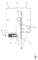
- a punching machine 1 has a C-shaped Machine frame 2 with an upper frame leg 3 and a lower frame legs 4.
- the tool storage 7 in common with the punch 6 in the direction of a lifting axis 8 rectilinearly movable and in Direction of a double arrow 9 about the lifting axis 8 itchably. Movements in the direction of the lifting axis 8 are from the tool storage 7 and the punch 6 at the work strokes for Machining of workpieces as well as to the working strokes subsequent return strokes executed.
- a rotation of the Tool storage 7 and the punch 6 is changed the rotational position of the punch 6 with respect to the lifting axis. 8 performed.
- the punch 6 acts with a not shown Punching tool in the form of a punching die together.
- a not shown Punching tool in the form of a punching die together.
- These is integrated in a usual way in a workpiece table 10, in turn on the lower frame leg 4 of the punching machine 1 is stored.
- the required for workpiece machining Relative movements of the sheet opposite the punch 6 and the die are by means of a in a pharynx 11 of the machine frame 2 accommodated coordinate guide 12 of conventional design executed.
- rotary / lifting drive 5 in the interior of a drive housing 13 a reversible electric rotary / lifting drive motor in its direction of rotation 14.
- rotary / Hubantriebsmotor 14 acts it is a torque motor with a housing-fixed stator 15th as well as a circumferential within the stator 15 about the lifting axis 8 Rotor 16.
- the rotor 16 of the rotary / Hubantriebsmotors 14th is direct and thus gearless with a Hubspindelmutter 17 connected. This sits on a drive spindle 18.
- a spindle axis 19 of the drive spindle 18 coincides with the lifting axis 8 together.
- At her to the tool storage 7 facing axial end has the Hubspindelmutter 17 on a flange 20.
- a conventional rolling bearing 21st intended for rotary mounting of Hubspindelmutter 17 on the drive housing 13 .
- a first detection device 22 Direction of rotation and angle of rotation of the lifting axis 8 and the Spindle axis 19 circumferential Hubspindelmutter 17 added. Together with the drive spindle 18 forms the Hubspindelmutter 17 a spindle drive 23, in the example shown designed as a ball screw.
- the axial projection 24 has a circular cylindrical Basic body, on which over a partial length of axial projection 24 radial wings 25 protrude. Own this As shown in FIG. 5 has a substantially rectangular cross-section and are in axial guide grooves 26 of a driver 27 recorded.
- the driver 27 surrounds the axial projection 24 and the drive spindle 18 concentric. Its axial guide grooves 26 form in cooperation with the radial wings 25 of the axial Approach 24 an axial guide 28 for the axial projection 24th and the thus integrally formed drive spindle 18.
- a conventional rolling bearing 29 takes over the pivot bearing of the driver 27 and the axial projection 24 and the drive spindle 18 on the drive housing 13.
- a second detection device 30 serves to detect the rotational position of the axial Approach 24 and at this provided tool storage. 7 or the punch 6 with respect to the lifting axis. 8
- the driver 27 optionally with the rotary / lifting drive motor 14 drivingly connected or driven by the rotary / Hubantriebsmotor 14 be separated.
- the taxable includes Switching device 31 a coupling / anti-rotation slide 32. This is on the outside of the driver 27 in axial Direction slidably guided.
- To the lifting axis 8 is the coupling / anti-rotation slide 32 by means of feather keys against rotation the driver 27 supported.
- For axial displacement of the coupling / anti-rotation slide 32 serves a plurality of actuation slides 33, which in turn on the drive housing 13th in the direction of the lifting axis 8 are movably guided and over a common pneumatic drive.
- the clutch / anti-rotation slide 32 engages with the free End of a flange 34 in the actuating slide 33 a.
- a radial flange surface 35 of the flange 34 on the clutch / anti-rotation slide 32 is a radial flange 36th on the flange 20 of Hubspindelmutter 17 opposite.
- the flange 34 of the clutch / anti-rotation slide 32 with another provided radial flange 37. This is assigned a Bearing surface 38 on the drive housing 13th
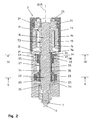
- Fig. 2 shows the electric rotary / lifting drive 5 in the punching workpiece machining associated operating state.
- the rotary / lifting drive motor 14 By means of the rotary / lifting drive motor 14 is the on the drive housing 13 rotatably and axially non-displaceably mounted Hubspindelmutter 17 in the respective direction of rotation about the lifting axis 8 or the spindle axis 19 is rotated.
- the coupling / anti-rotation slide 32 of the controllable switching device 31 is by means of the actuating slide 33 in its lower end position postponed.
- the driver 27 is of the rotary / Hubantriebsmotor 14 thus separated in terms of drive.
- the radial flange surface 37 on the clutch / anti-rotation slide 32 is supported on the contact surface 38 of the drive housing 13 off.
- the drive housing 13 acting normal force is the clutch / anti-rotation slide 32 against the drive housing 13 against Rotation about the lifting axis 8 fixed.
- the coupling / anti-rotation slide 32 are the driver 27 and the on this rotationally mounted axial projection 24 and with this integrally formed drive spindle 18 against rotation secured around the lifting axle 8.
- the coupling / anti-rotation slide forms 32 in cooperation with the driver 27 and the drive housing 13 a rotation lock 39 for the drive spindle 18.
- the drive housing 13 serves as Mit deliberatelywiderlager.
- the rotation lock 39 prevents entrainment of the drive spindle 18 by the revolving around the lifting axis 8 Hubspindelmutter 17.
- the Hubspindelmutter 17 shifts the latter jointly with the axial projection 24, the tool storage provided thereon 7 and held in the tool storage 7 punch 6th in the direction of the lifting axis 8.
- the tool storage 7 and the punch 6 with a working stroke in the direction of the working workpiece lowered or following a Working stroke with a return stroke opposite the machined Workpiece retracted.
- the electric rotary / lifting drive 5 then transferred when the rotational position of the tool storage 7 and the punch 6 with respect to the lifting axis 8 is to change.
- the driver 27 and the rotary / lifting drive motor 14 via the clutch / anti-rotation slide 32 of the controllable switching device 31 drivingly connected with each other.
- the clutch / anti-rotation slide 32 by means of the actuating slide 33 moved to an axial position when taking he with its radial flange surface 35 to the radial flange surface 36 of the Hubspindelmutter 17 is pressed. Consequently results between the Hubspindelmutter 17 and the clutch / anti-rotation slide 32 a positive connection.
- All functions of the electric rotary / lifting drive 5 are numerically controlled. Part of the numerical control are i.a. the first detection device 22 and the second detection device 30.
- the first detection device 22 serves for the controlled execution of the working strokes as well as the return strokes of the punch 6 in the direction of the lifting axis 8.
- the second detection device 30 is used to control the rotation adjustment of the punch 6 about the lifting axis 8.
- the rotary / lifting drive motor 14 functions both as a rotary drive motor and as a lift drive motor. With the rotary adjustment of the punch 6 is a corresponding rotation of the setting with the punch 6th cooperating punching die made.
- the electric rotary / lifting drive 55 can on the punching machine 1 instead of the electric rotary / lifting drive 5 are used.
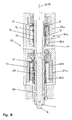
- the electric rotary / lifting drive 55 comprises a Rotary drive motor 64a and a Hubantriebsmotor 64b. at Both motors are torque motors.
- the rotary drive motor 64a has a stator 65a and a rotor 66a.
- the rotor 66a is directly connected to a driver 77 and commonly runs during operation of the rotary drive motor 64a with the driver 77 to the lifting axis 8 of the rotary / lifting drive 55 um.
- the driver 77 supports one with a drive spindle 68 integrally formed axial projection 74th Notwithstanding the axial projection 24 according to FIGS. 2 to 5 is the axial projection 74 of FIG. 6 designed as a hollow cylinder.
- Hubspindelmutter 67 On the drive spindle 68 sits a Hubspindelmutter 67. This is rotatable about the lifting axis 8 and in the direction of the lifting axis 8 non-displaceably stored. Without the interposition of a gearbox is the Hubspindelmutter 67 with a rotor 66 b of Hubantriebsmotors 64b connected. Associated with the rotor 66b a stator 65b of the lift drive motor 64b. A spindle axis 19 the drive spindle 68 coincides with the lifting axis 8. deviant from the drive spindle 18 according to FIGS. 2 to 5 is the drive spindle 68 of FIG. 6 designed as a hollow spindle.
- a tool storage 7 with a punch 6 is at a Plunger 81 arranged, which in turn in the axial receptacle the drive spindle 68 is fixed.
- the Hubspindelmutter 67 and the drive spindle 68 form a spindle drive 73, as well as the spindle drive 23 according to FIGS. 2 to 5 as a ball screw is executed.
- Hubantriebsmotor 64b For punching workpiece machining is exclusively the Hubantriebsmotor 64b operated.
- the communal with the Rotor 66b of Hubantriebsmotors 64b revolving Hubspindelmutter 67 drives the drive spindle 68 in the direction of the stroke axis 8 and the spindle axis 19 at.
- the Hubspindelmutter 67 is the drive spindle 68th and with this the tool storage 7 with the punch 6 too the workpiece to be machined lowered or opposite to the retracted machined workpiece.
- the rotary drive motor 64a is at punching operation of the electric rotary / lifting drive 55th switched off.
- the rotor 66a is with the rotary drive motor off 64a against rotation about the lifting axis 8 in the direction of rotation blocked. The same applies to the form-locking on the rotor 66a As a result, the deactivated Rotary drive motor 64a in common with the driver 77 a rotation lock for the displacing in the axial direction Drive spindle 68.
- the functions of the electric rotary / lifting drive 55 are numerically controlled. As components of numerical control are u.a. not shown in detail or explained detection devices for receiving speed or angle of rotation and direction of rotation of Hubspindelmutter 67 and the drive spindle 68 provided.
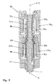
- Fig. 7 shows an electric rotary / lifting drive 85 with as Torque motors trained drive motors 94a, 94b.
- the drive motor 94a includes a stator 95a and a rotor 96a
- the drive motor 94b has a stator 95b and a rotor 96b.
- the rotor 96a is with a Hubspindelmutter 97a, the rotor 96b directly connected to a Hubspindelmutter 97b.
- the Hubspindelmutter 97a sits on a drive spindle 98a, the Hubspindelmutter 97b on a drive spindle 98b.
- the Hubspindelmuttern 97a, 97b and the associated motors 95a, 95b of the drive motors 94a, 94b are with mutual axial coverage arranged.
- Both drive spindles 98a, 98b are designed as hollow spindles. In their interior, the drive spindles 98a, 98b take a Plunger 111 on, on the workpiece side end of the tool storage 7 is provided with the punch 6. The drive spindles 98a, 98b are about the plunger 111 to a unit connected with each other. A lifting axis 8 of the rotary / lifting drive 85 coincides with a common spindle axis 19 of the drive spindles 98a, 98b together.
- the Hubspindelmutter 97a forms together with the drive spindle 98a a spindle drive 103a, the Hubspindelmutter 97b with the drive spindle 98b a spindle drive 103b.
- the spindle drives 103a, 103b have opposing threads, are otherwise but identical.
- the two drive motors 94a, 94b For punching workpiece machining, the two drive motors 94a, 94b at the same speed, but operated in opposite directions. The result is a shift of the drive spindles 98a, 98b and the tool storage 7 and the punch 6 in the direction of the lifting axis 8.
- the counter-rotating Motor As a result of the counter-rotating Motor istes act the Hubspindelmutter 97 a and the Drive motor 94a as anti-rotation device for the drive spindle 98b, the Hubspindelmutter 97b and the drive motor 94b as Anti-rotation device for the drive spindle 98a.
- the Drive motors 94a, 94b For rotational adjustment of the tool storage 7 and the punch 6 about the lifting axis 8 and the spindle axis 19 are the Drive motors 94a, 94b with matching speed and operated identical direction of rotation. This results in a joint Rotary movement of Hubspindelmutter 97 a and the Drive spindle 98a and the Hubspindelmutter 97b and the drive spindle 98b. A relative rotational movement between the Hubspindelmutter 97a and the drive spindle 98a and the Hubspindelmutter 97b and the drive spindle 98b is omitted. In In this operating state, the Hubspindelmuttern 97a, 97b act as a driver for the drive spindles 98a, 98b.
- the drive motors 94a, 94b form rotary drive motors or lifting drive motors.
Landscapes
- Engineering & Computer Science (AREA)
- Mechanical Engineering (AREA)
- Manufacture Of Motors, Generators (AREA)
- Press Drives And Press Lines (AREA)
- Perforating, Stamping-Out Or Severing By Means Other Than Cutting (AREA)
- Punching Or Piercing (AREA)
Abstract
Description
- Fig. 1
- eine Stanzmaschine mit einer ersten Bauart eines elektrischen Dreh-/Hubantriebes für ein Stanzoberwerkzeug in der teilgeschnittenen Seitenansicht,
- Fig. 2
- den Dreh-/Hubantrieb gemäß Fig. 1 in einem ersten Betriebszustand,
- Fig. 3
- den Dreh-/Hubantrieb gemäß den Fign. 1 und 2 in einem zweiten Betriebszustand,
- Fig. 4
- einen Schnitt mit einer in Fig. 2 senkrecht zu der Zeichenebene und entlang der Linie IV-IV verlaufenden Schnittebene,
- Fig. 5
- einen Schnitt mit einer in Fig. 2 senkrecht zu der Zeichenebene und entlang der Linie V-V verlaufenden Schnittebene,
- Fig. 6
- eine zweite Bauart eines elektrischen Dreh-/Hubantriebes für ein Stanzoberwerkzeug einer Stanzmaschine und
- Fig. 7
- eine dritte Bauart eines elektrischen Dreh-/Hubantriebes für ein Stanzoberwerkzeug einer Stanzmaschine.
Claims (10)
- Stanzmaschine mit einer Werkzeuglagerung (7) für ein Stanzwerkzeug (6) sowie mit einem Dreh-/Hubantrieb (5, 55, 85), mittels dessen die Werkzeuglagerung (7) in Richtung einer Hubachse (8) zu dem Arbeitsbereich der Stanzmaschine hin und zurück bewegbar und um die Hubachse (8) dreheinstellbar ist und der einen elektrischen Drehantriebsmotor (14, 64a; 94a, 94b), einen elektrischen Hubantriebsmotor (14, 64b; 94a, 94b) sowie eine mit der Werkzeuglagerung (7) bewegungsverbundene Antriebsspindel (18, 68; 98a, 98b) umfasst, wobei zur Bewegung der Werkzeuglagerung (7) in Richtung der Hubachse (8) eine auf der Antriebsspindel (18, 68; 98a, 98b) aufsitzende Hubspindelmutter (17, 67; 97a, 97b) mittels des Hubantriebsmotors (14, 64b; 94a, 94b) relativ zu der Antriebsspindel (18, 68; 98a, 98b) drehbar und die Antriebsspindel (18, 68; 98a, 98b) in Richtung einer Spindelachse (19) verlagerbar ist und wobei zur Dreheinstellung der Werkzeuglagerung (7) um die Hubachse (8) ein um die Spindelachse (19) der Antriebsspindel (18, 68; 98a, 98b) drehbarer Mitnehmer (27, 77; 97a, 97b) mittels des Drehantriebsmotors (14, 64a; 94a, 94b) unter Mitnahme der Antriebsspindel (18, 68; 98a, 98b) um die Spindelachse (19) drehbar ist, dadurch gekennzeichnet, dass die Hubspindelmutter (17, 67; 97a, 97b) an einem um die Spindelachse (19) der Antriebsspindel (18, 68; 98a, 98b) umlaufenden Rotor (16, 66b; 96a, 96b) des Hubantriebsmotors (14, 64b; 94a, 94b) und/oder der Mitnehmer (77; 97a, 97b) an einem um die Spindelachse (19) der Antriebsspindel (68; 98a, 98b) umlaufenden Rotor (66a; 96a, 96b) des Drehantriebsmotors (64a; 94a, 94b) angebracht ist und dass die Hubspindelmutter (17, 67; 97a, 97b) sowie der zugeordnete Rotor (16, 66b; 96a, 96b) innerhalb eines Stators (15, 65b; 95a, 95b) des Hubantriebsmötors (14, 64b; 94, 94b) und/oder der Mitnehmer (77; 97a, 97b) sowie der zugeordnete Rotor (66a; 96a, 96b) innerhalb eines Stators (65a; 95a, 95b) des Drehantriebsmotors (64a; 94a, 94b) angeordnet sind, wobei sich die Hubspindelmutter (17, 67; 97a, 97b) und der Stator (15, 65b; 95a, 95b) des Hubantriebsmotors (14, 64b; 94a, 94b) und/oder der Mitnehmer (77; 97a, 97b) und der Stator (65a; 95a, 95b) des Drehantriebsmotors (64a; 94a, 94b) in Richtung der Spindelachse (19) wenigstens teilweise überdecken.
- Stanzmaschine nach dem Oberbegriff von Anspruch 1, dadurch gekennzeichnet, dass der Drehantriebsmotor (14) und der Hubantriebsmotor (14) gemeinschaftlich von einem Dreh-/Hubantriebsmotor (14) gebildet sind und dass eine steuerbare Schalteinrichtung (31) vorgesehen ist, mittels derer der Mitnehmer (27) für die Antriebsspindel (18) wahlweise mit dem Dreh-/Hubantriebsmotor (14) antriebsmäßig verbindbar oder von dem Dreh-/Hubantriebsmotor (14) antriebsmäßig trennbar ist, wobei bei antriebsmäßiger Verbindung von Mitnehmer (27) und Dreh-/Hubantriebsmotor (14) der Mitnehmer (27) mittels des Dreh-/Hubantriebsmotors (14) unter Mitnahme der Antriebsspindel (18) um die Spindelachse (19) drehbar ist und wobei bei antriebsmäßiger Trennung von Mitnehmer (27) und Dreh-/Hubantriebsmotor (14) die Hubspindelmutter (17) mittels des Dreh-/Hubantriebsmotors (14) unter Verlagerung der Antriebsspindel (18) in Richtung der Spindelachse (19) relativ zu der Antriebsspindel (18) drehbar ist.
- Stanzmaschine nach Anspruch 2, dadurch gekennzeichnet, dass der Mitnehmer (27) für die Antriebsspindel (18) mittels der steuerbaren Schalteinrichtung (31) an der mit dem Dreh-/Hubantriebsmotor (14) antriebsmäßig verbundenen Hubspindelmutter (17) mit dem Dreh-/Hubantriebsmotor (14) antriebsmäßig verbindbar ist.
- Stanzmaschine nach Anspruch 2 oder 3, dadurch gekennzeichnet, dass die Hubspindelmutter (17) und der Mitnehmer (27) für die Antriebsspindel (18) entlang der Spindelachse (19) nebeneinander angeordnet sind und dass die steuerbare Schalteinrichtung (31) einen Kupplungsschieber umfasst, der gesteuert längs der Spindelachse (19) verschiebbar ist und die Hubspindelmutter (17) sowie den Mitnehmer (27) in einer ersten Verschiebeposition in Drehrichtung der Hubspindelmutter (17) drehfest miteinander verbindet und in einer weiteren Verschiebeposition die drehfeste Verbindung von Hubspindelmutter (17) und Mitnehmer (27) freigibt.
- Stanzmaschine nach einem der Ansprüche 2 bis 4, dadurch gekennzeichnet, dass die Antriebsspindel (18) bei antriebsmäßiger Trennung des Mitnehmers (27) für die Antriebsspindel (18) von dem Dreh-/Hubantriebsmotor (14) mittels einer Drehsicherung (39) gegen Drehung um die Spindelachse (19) sicherbar ist.
- Stanzmaschine nach einem der Ansprüche 2 bis 5, dadurch gekennzeichnet, dass die Drehsicherung (39) für die Antriebsspindel (18) einen Drehsicherungsschieber umfasst, der gesteuert längs der Spindelachse (19) verschiebbar ist und der den Mitnehmer (27) für die Antriebsspindel (18) in einer ersten Verschiebeposition an einem Mitnehmerwiderlager (13) gegen Drehung um die Spindelachse (19) festlegt und in einer weiteren Verschiebeposition von dem Mitnehmerwiderlager (13) zur Drehung um die Spindelachse (19) freigibt.
- Stanzmaschine nach einem der Ansprüche 2 bis 6, dadurch gekennzeichnet, dass der Kupplungsschieber der steuerbaren Schalteinrichtung (31) und der Drehsicherungsschieber der Drehsicherung (39) des Mitnehmers (27) für die Antriebsspindel (18) gemeinschaftlich von einem Kupplungs-/Drehsicherungsschieber (32) gebildet sind, der gesteuert längs der Spindelachse (19) verschiebbar ist und der in einer ersten Verschiebeposition den Mitnehmer (27) von dem Mitnehmerwiderlager (13) zur Drehung um die Spindelachse (19) freigibt und gleichzeitig den Mitnehmer (27) und die Hubspindelmutter (17) in Drehrichtung der Hubspindelmutter (17) drehfest miteinander verbindet und der in einer weiteren Verschiebeposition die drehfeste Verbindung von Hubspindelmutter (17) und Mitnehmer (27) freigibt und gleichzeitig den Mitnehmer (27) an einem Mitnehmerwiderlager (13) gegen Drehung um die Spindelachse (19) festlegt.
- Stanzmaschine nach einem der Ansprüche 2 bis 7, dadurch gekennzeichnet, dass die Hubspindelmutter (17) an einem um die Spindelachse (19) der Antriebsspindel (18) umlaufenden Rotor (16) des Dreh-/Hubantriebsmotors (14) angebracht ist und dass die Hubspindelmutter (17) sowie der Rotor (16) innerhalb eines Stators (15) des Dreh-/Hubantriebsmotors (14) angeordnet sind.
- Stanzmaschine nach einem der Ansprüche 2 bis 8, dadurch gekennzeichnet, dass sich die Hubspindelmutter (17) und der Stator (15) des Dreh-/Hubantriebsmotors (14) in Richtung der Spindelachse (19) wenigstens teilweise überdecken.
- Stanzmaschine nach einem der vorhergehenden Ansprüche, dadurch gekennzeichnet, dass als Hubantriebsmotor (14, 64b; 94a, 94b) und/oder als Drehantriebsmotor (14, 64a; 94a, 94b) und/oder als Dreh-/Hubantriebsmotor (14) ein Torque-Motor vorgesehen ist.
Priority Applications (9)
| Application Number | Priority Date | Filing Date | Title |
|---|---|---|---|
| DE200450007280 DE502004007280D1 (de) | 2004-05-27 | 2004-05-27 | Stanzmaschine mit elektrischem Dreh-/Hubantrieb |
| AT04012523T ATE396805T1 (de) | 2004-05-27 | 2004-05-27 | Stanzmaschine mit elektrischem dreh-/hubantrieb |
| PL04012523T PL1600225T3 (pl) | 2004-05-27 | 2004-05-27 | Wytłaczarka z elektrycznym napędem obrotowo-skokowym |
| ES04012523T ES2305611T3 (es) | 2004-05-27 | 2004-05-27 | Troqueladora con un accionamiento de giro / carrera electrico. |
| EP20040012523 EP1600225B1 (de) | 2004-05-27 | 2004-05-27 | Stanzmaschine mit elektrischem Dreh-/Hubantrieb |
| CNB2005800172168A CN100427236C (zh) | 2004-05-27 | 2005-05-25 | 具有电气旋转/升降驱动装置的冲压机 |
| PCT/EP2005/005636 WO2005118177A1 (de) | 2004-05-27 | 2005-05-25 | Stanzmaschine mit elektrischem dreh-/hubantrieb |
| JP2007513797A JP4705635B2 (ja) | 2004-05-27 | 2005-05-25 | 電気的な回転・昇降駆動装置を備えた打抜き機 |
| US11/563,582 US7717021B2 (en) | 2004-05-27 | 2006-11-27 | Punch tool lift spindle |
Applications Claiming Priority (1)
| Application Number | Priority Date | Filing Date | Title |
|---|---|---|---|
| EP20040012523 EP1600225B1 (de) | 2004-05-27 | 2004-05-27 | Stanzmaschine mit elektrischem Dreh-/Hubantrieb |
Publications (2)
| Publication Number | Publication Date |
|---|---|
| EP1600225A1 true EP1600225A1 (de) | 2005-11-30 |
| EP1600225B1 EP1600225B1 (de) | 2008-05-28 |
Family
ID=34925144
Family Applications (1)
| Application Number | Title | Priority Date | Filing Date |
|---|---|---|---|
| EP20040012523 Expired - Lifetime EP1600225B1 (de) | 2004-05-27 | 2004-05-27 | Stanzmaschine mit elektrischem Dreh-/Hubantrieb |
Country Status (9)
| Country | Link |
|---|---|
| US (1) | US7717021B2 (de) |
| EP (1) | EP1600225B1 (de) |
| JP (1) | JP4705635B2 (de) |
| CN (1) | CN100427236C (de) |
| AT (1) | ATE396805T1 (de) |
| DE (1) | DE502004007280D1 (de) |
| ES (1) | ES2305611T3 (de) |
| PL (1) | PL1600225T3 (de) |
| WO (1) | WO2005118177A1 (de) |
Cited By (6)
| Publication number | Priority date | Publication date | Assignee | Title |
|---|---|---|---|---|
| EP1839768A1 (de) * | 2006-03-31 | 2007-10-03 | Campex SRL | Stanzpresse, insbesondere zur Ablängung und Endenbearbeitung von Flachstabmaterial für Fensterbeschläge |
| WO2008012188A1 (de) * | 2006-07-24 | 2008-01-31 | Siemens Aktiengesellschaft | Presse |
| DE102008011772A1 (de) * | 2008-02-28 | 2009-09-03 | Bernd Hansen | Trennvorrichtung |
| CN102357588A (zh) * | 2011-10-30 | 2012-02-22 | 山东华力电机集团股份有限公司 | 冷轧卷料硅钢片一落二冲模 |
| CN102366791A (zh) * | 2011-09-29 | 2012-03-07 | 合肥常青机械制造有限责任公司 | 前灯线束盖板切边冲孔模 |
| TWI572422B (zh) * | 2015-06-04 | 2017-03-01 | Silicone sheet continuous die device |
Families Citing this family (10)
| Publication number | Priority date | Publication date | Assignee | Title |
|---|---|---|---|---|
| EP1600224A1 (de) * | 2004-05-27 | 2005-11-30 | Trumpf Werkzeugmaschinen GmbH + Co. KG | Werkzeugmaschine mit einem Hubantrieb zur Beaufschlagung eines Werkstückes mit einem Bearbeitungswerkzeug |
| DE102007054533C5 (de) * | 2007-11-15 | 2012-04-05 | Hoerbiger Automatisierungstechnik Holding Gmbh | CNC-Stanzmaschine |
| US20110185874A1 (en) * | 2010-01-29 | 2011-08-04 | Jason Blair | Punch Press |
| CN105263648B (zh) * | 2013-05-27 | 2018-09-28 | 萨尔瓦尼尼意大利股份公司 | 冲压设备 |
| CN106181510B (zh) * | 2016-08-18 | 2019-01-25 | 北京超同步伺服股份有限公司 | 电动打刀缸和包括该电动打刀缸的电主轴 |
| CN106273608B (zh) * | 2016-11-03 | 2018-04-10 | 西安思源学院 | 一种双电机螺旋副直驱式回转头压力机 |
| CN109396319B (zh) * | 2018-07-27 | 2024-04-05 | 宾科精密部件(中国)有限公司 | 压铆装置 |
| DE102019116968B4 (de) * | 2019-06-18 | 2025-07-31 | Benteler Automobiltechnik Gmbh | Stoßantrieb für ein linear zu bewegendes Werkzeug, Blechbauteil sowie Verfahren zum Schneiden eines Blechbauteils |
| CH716574A1 (de) * | 2019-09-10 | 2021-03-15 | Berhalter Ag | Stanzmaschine zum Stanzen von Etiketten und Deckeln. |
| CN114799841A (zh) * | 2022-04-11 | 2022-07-29 | 东莞市精心自动化设备科技有限公司 | 一种锁紧机构及其全自动锁紧机 |
Citations (2)
| Publication number | Priority date | Publication date | Assignee | Title |
|---|---|---|---|---|
| JPH04172133A (ja) * | 1990-11-06 | 1992-06-19 | Amada Co Ltd | パンチプレス |
| JPH11207560A (ja) * | 1998-01-29 | 1999-08-03 | Amada Eng Center Co Ltd | 一軸方向駆動装置 |
Family Cites Families (12)
| Publication number | Priority date | Publication date | Assignee | Title |
|---|---|---|---|---|
| US1533236A (en) * | 1921-12-09 | 1925-04-14 | Bethlehem Steel Corp | Process of locally heat-treating hardened-steel articles |
| NL8902274A (nl) * | 1989-09-12 | 1991-04-02 | Brouwer & Co Machine | Ponsmachine. |
| CN2225351Y (zh) * | 1995-06-12 | 1996-04-24 | 李抚生 | 双向电磁驱动高速冲压机械 |
| JPH0929698A (ja) * | 1995-07-12 | 1997-02-04 | Hitachi Metals Ltd | 電動式パンチユニット |
| CN2369838Y (zh) * | 1998-04-03 | 2000-03-22 | 萧焕昌 | 一种适用于生产高强度水泥块的冲压机 |
| US6280124B1 (en) * | 1999-03-18 | 2001-08-28 | Ballado Investments Inc. | Spindle with linear motor for axially moving a tool |
| JP2001009536A (ja) * | 1999-06-29 | 2001-01-16 | Japitto Kk | 打ち抜き式穴空け工具 |
| JP2002086298A (ja) * | 2000-09-13 | 2002-03-26 | Uht Corp | パンチングマシンにおけるパンチの駆動構造 |
| US20020045521A1 (en) * | 2000-10-16 | 2002-04-18 | Hideki Mochida | Spindle unit for a machine tool |
| US7112019B2 (en) * | 2002-02-22 | 2006-09-26 | Ballado Investments Inc. | Pneumatic spindle with means to direct the bearing air towards the tool-holding collet |
| EP1502673B1 (de) * | 2003-07-26 | 2006-04-26 | Trumpf Werkzeugmaschinen GmbH + Co. KG | Werkzeugmaschine mit Werkzeug-Hubantrieb |
| EP1600223A1 (de) * | 2004-05-27 | 2005-11-30 | Trumpf Werkzeugmaschinen GmbH + Co. KG | Stanzmaschine mit einem motorischen Dreh- / Hubantrieb |
-
2004
- 2004-05-27 ES ES04012523T patent/ES2305611T3/es not_active Expired - Lifetime
- 2004-05-27 PL PL04012523T patent/PL1600225T3/pl unknown
- 2004-05-27 DE DE200450007280 patent/DE502004007280D1/de not_active Expired - Lifetime
- 2004-05-27 AT AT04012523T patent/ATE396805T1/de not_active IP Right Cessation
- 2004-05-27 EP EP20040012523 patent/EP1600225B1/de not_active Expired - Lifetime
-
2005
- 2005-05-25 JP JP2007513797A patent/JP4705635B2/ja not_active Expired - Lifetime
- 2005-05-25 WO PCT/EP2005/005636 patent/WO2005118177A1/de not_active Ceased
- 2005-05-25 CN CNB2005800172168A patent/CN100427236C/zh not_active Expired - Lifetime
-
2006
- 2006-11-27 US US11/563,582 patent/US7717021B2/en not_active Expired - Lifetime
Patent Citations (2)
| Publication number | Priority date | Publication date | Assignee | Title |
|---|---|---|---|---|
| JPH04172133A (ja) * | 1990-11-06 | 1992-06-19 | Amada Co Ltd | パンチプレス |
| JPH11207560A (ja) * | 1998-01-29 | 1999-08-03 | Amada Eng Center Co Ltd | 一軸方向駆動装置 |
Non-Patent Citations (2)
| Title |
|---|
| PATENT ABSTRACTS OF JAPAN vol. 0164, no. 74 (M - 1319) 2 October 1992 (1992-10-02) * |
| PATENT ABSTRACTS OF JAPAN vol. 1999, no. 13 30 November 1999 (1999-11-30) * |
Cited By (8)
| Publication number | Priority date | Publication date | Assignee | Title |
|---|---|---|---|---|
| EP1839768A1 (de) * | 2006-03-31 | 2007-10-03 | Campex SRL | Stanzpresse, insbesondere zur Ablängung und Endenbearbeitung von Flachstabmaterial für Fensterbeschläge |
| WO2008012188A1 (de) * | 2006-07-24 | 2008-01-31 | Siemens Aktiengesellschaft | Presse |
| US8065956B2 (en) | 2006-07-24 | 2011-11-29 | Siemens Aktiengesellschaft | Press |
| DE102008011772A1 (de) * | 2008-02-28 | 2009-09-03 | Bernd Hansen | Trennvorrichtung |
| US8578828B2 (en) | 2008-02-28 | 2013-11-12 | Bernd Hansen | Separating device |
| CN102366791A (zh) * | 2011-09-29 | 2012-03-07 | 合肥常青机械制造有限责任公司 | 前灯线束盖板切边冲孔模 |
| CN102357588A (zh) * | 2011-10-30 | 2012-02-22 | 山东华力电机集团股份有限公司 | 冷轧卷料硅钢片一落二冲模 |
| TWI572422B (zh) * | 2015-06-04 | 2017-03-01 | Silicone sheet continuous die device |
Also Published As
| Publication number | Publication date |
|---|---|
| JP4705635B2 (ja) | 2011-06-22 |
| ATE396805T1 (de) | 2008-06-15 |
| US20070240551A1 (en) | 2007-10-18 |
| ES2305611T3 (es) | 2008-11-01 |
| EP1600225B1 (de) | 2008-05-28 |
| WO2005118177A1 (de) | 2005-12-15 |
| CN1960818A (zh) | 2007-05-09 |
| PL1600225T3 (pl) | 2008-10-31 |
| JP2008500180A (ja) | 2008-01-10 |
| CN100427236C (zh) | 2008-10-22 |
| DE502004007280D1 (de) | 2008-07-10 |
| US7717021B2 (en) | 2010-05-18 |
Similar Documents
| Publication | Publication Date | Title |
|---|---|---|
| EP1600225B1 (de) | Stanzmaschine mit elektrischem Dreh-/Hubantrieb | |
| EP1748853B1 (de) | Stanzmaschine mit einem motorischen dreh-/hubantrieb | |
| EP1399293B9 (de) | Werkzeugmaschine mit werkzeugrevolver | |
| EP2170553B1 (de) | Werkzeugrevolvereinheit für eine werkzeugmaschine | |
| EP2480372B1 (de) | Antriebsvorrichtung für werkzeugrevolver | |
| EP2158998B1 (de) | Werkzeugrevolver | |
| EP0261312A2 (de) | Vorrichtung zur Winkelpositionierung einer Arbeitsspindel | |
| EP0279236B1 (de) | Drehantrieb für Schwenktüren insbesondere an Fahrzeugen | |
| EP1502673A1 (de) | Werkzeugmaschine mit Werkzeug-Hubantrieb | |
| DE4201849C1 (de) | ||
| EP1772231B1 (de) | Mehrspindeldrehmaschine mit einer Bearbeitungseinheit auf einem Kreuzschlitten | |
| EP2185318B1 (de) | Werkzeugrevolver | |
| EP1128930B1 (de) | Werkzeugkopf mit spindellagerung | |
| DE102020211506B4 (de) | Ausleger-Arbeitsvorrichtung | |
| EP3381605B1 (de) | Mehrspindeldrehmaschine | |
| WO2006092110A1 (de) | Werkzeugrevolver mit einem drehantreibbaren werkzeug an der stirnseite | |
| EP1878550B1 (de) | Spindeleinheit für ein mehrspindeliges Bohraggregat | |
| DE2837581C2 (de) | ||
| EP2282869B1 (de) | Vorrichtung zur werkstückpositionierung | |
| DE4124228A1 (de) | Werkstueckhalter fuer werkzeugmaschinen | |
| EP1163976A1 (de) | Drehantrieb mit einer Drehzahlumschalteinrichtung für eine Werkzeughaltevorrichtung | |
| EP3498421A1 (de) | Werkzeugwechseleinrichtung | |
| EP1238729B1 (de) | Drehmaschine | |
| DE3425254C2 (de) | ||
| DE102023111023A1 (de) | Positioniersystem |
Legal Events
| Date | Code | Title | Description |
|---|---|---|---|
| PUAI | Public reference made under article 153(3) epc to a published international application that has entered the european phase |
Free format text: ORIGINAL CODE: 0009012 |
|
| AK | Designated contracting states |
Kind code of ref document: A1 Designated state(s): AT BE BG CH CY CZ DE DK EE ES FI FR GB GR HU IE IT LI LU MC NL PL PT RO SE SI SK TR |
|
| AX | Request for extension of the european patent |
Extension state: AL HR LT LV MK |
|
| 17P | Request for examination filed |
Effective date: 20060509 |
|
| AKX | Designation fees paid |
Designated state(s): AT BE BG CH CY CZ DE DK EE ES FI FR GB GR HU IE IT LI LU MC NL PL PT RO SE SI SK TR |
|
| GRAP | Despatch of communication of intention to grant a patent |
Free format text: ORIGINAL CODE: EPIDOSNIGR1 |
|
| GRAS | Grant fee paid |
Free format text: ORIGINAL CODE: EPIDOSNIGR3 |
|
| GRAA | (expected) grant |
Free format text: ORIGINAL CODE: 0009210 |
|
| AK | Designated contracting states |
Kind code of ref document: B1 Designated state(s): AT BE BG CH CY CZ DE DK EE ES FI FR GB GR HU IE IT LI LU MC NL PL PT RO SE SI SK TR |
|
| REG | Reference to a national code |
Ref country code: GB Ref legal event code: FG4D Free format text: NOT ENGLISH |
|
| REG | Reference to a national code |
Ref country code: CH Ref legal event code: EP |
|
| REF | Corresponds to: |
Ref document number: 502004007280 Country of ref document: DE Date of ref document: 20080710 Kind code of ref document: P |
|
| REG | Reference to a national code |
Ref country code: IE Ref legal event code: FG4D Free format text: LANGUAGE OF EP DOCUMENT: GERMAN |
|
| PG25 | Lapsed in a contracting state [announced via postgrant information from national office to epo] |
Ref country code: SI Free format text: LAPSE BECAUSE OF FAILURE TO SUBMIT A TRANSLATION OF THE DESCRIPTION OR TO PAY THE FEE WITHIN THE PRESCRIBED TIME-LIMIT Effective date: 20080528 |
|
| REG | Reference to a national code |
Ref country code: PL Ref legal event code: T3 |
|
| REG | Reference to a national code |
Ref country code: ES Ref legal event code: FG2A Ref document number: 2305611 Country of ref document: ES Kind code of ref document: T3 |
|
| PG25 | Lapsed in a contracting state [announced via postgrant information from national office to epo] |
Ref country code: NL Free format text: LAPSE BECAUSE OF FAILURE TO SUBMIT A TRANSLATION OF THE DESCRIPTION OR TO PAY THE FEE WITHIN THE PRESCRIBED TIME-LIMIT Effective date: 20080528 |
|
| NLV1 | Nl: lapsed or annulled due to failure to fulfill the requirements of art. 29p and 29m of the patents act | ||
| REG | Reference to a national code |
Ref country code: IE Ref legal event code: FD4D |
|
| PG25 | Lapsed in a contracting state [announced via postgrant information from national office to epo] |
Ref country code: SE Free format text: LAPSE BECAUSE OF FAILURE TO SUBMIT A TRANSLATION OF THE DESCRIPTION OR TO PAY THE FEE WITHIN THE PRESCRIBED TIME-LIMIT Effective date: 20080828 Ref country code: PT Free format text: LAPSE BECAUSE OF FAILURE TO SUBMIT A TRANSLATION OF THE DESCRIPTION OR TO PAY THE FEE WITHIN THE PRESCRIBED TIME-LIMIT Effective date: 20081028 Ref country code: DK Free format text: LAPSE BECAUSE OF FAILURE TO SUBMIT A TRANSLATION OF THE DESCRIPTION OR TO PAY THE FEE WITHIN THE PRESCRIBED TIME-LIMIT Effective date: 20080528 Ref country code: IE Free format text: LAPSE BECAUSE OF FAILURE TO SUBMIT A TRANSLATION OF THE DESCRIPTION OR TO PAY THE FEE WITHIN THE PRESCRIBED TIME-LIMIT Effective date: 20080528 |
|
| PG25 | Lapsed in a contracting state [announced via postgrant information from national office to epo] |
Ref country code: SK Free format text: LAPSE BECAUSE OF FAILURE TO SUBMIT A TRANSLATION OF THE DESCRIPTION OR TO PAY THE FEE WITHIN THE PRESCRIBED TIME-LIMIT Effective date: 20080528 Ref country code: RO Free format text: LAPSE BECAUSE OF FAILURE TO SUBMIT A TRANSLATION OF THE DESCRIPTION OR TO PAY THE FEE WITHIN THE PRESCRIBED TIME-LIMIT Effective date: 20080528 |
|
| PLBE | No opposition filed within time limit |
Free format text: ORIGINAL CODE: 0009261 |
|
| STAA | Information on the status of an ep patent application or granted ep patent |
Free format text: STATUS: NO OPPOSITION FILED WITHIN TIME LIMIT |
|
| PG25 | Lapsed in a contracting state [announced via postgrant information from national office to epo] |
Ref country code: EE Free format text: LAPSE BECAUSE OF FAILURE TO SUBMIT A TRANSLATION OF THE DESCRIPTION OR TO PAY THE FEE WITHIN THE PRESCRIBED TIME-LIMIT Effective date: 20080528 Ref country code: BG Free format text: LAPSE BECAUSE OF FAILURE TO SUBMIT A TRANSLATION OF THE DESCRIPTION OR TO PAY THE FEE WITHIN THE PRESCRIBED TIME-LIMIT Effective date: 20080828 |
|
| 26N | No opposition filed |
Effective date: 20090303 |
|
| BERE | Be: lapsed |
Owner name: TRUMPF WERKZEUGMASCHINEN G.M.B.H. + CO. KG Effective date: 20090531 |
|
| PG25 | Lapsed in a contracting state [announced via postgrant information from national office to epo] |
Ref country code: MC Free format text: LAPSE BECAUSE OF NON-PAYMENT OF DUE FEES Effective date: 20090531 |
|
| REG | Reference to a national code |
Ref country code: CH Ref legal event code: PL |
|
| GBPC | Gb: european patent ceased through non-payment of renewal fee |
Effective date: 20090527 |
|
| PG25 | Lapsed in a contracting state [announced via postgrant information from national office to epo] |
Ref country code: CH Free format text: LAPSE BECAUSE OF NON-PAYMENT OF DUE FEES Effective date: 20090531 Ref country code: LI Free format text: LAPSE BECAUSE OF NON-PAYMENT OF DUE FEES Effective date: 20090531 |
|
| PG25 | Lapsed in a contracting state [announced via postgrant information from national office to epo] |
Ref country code: GB Free format text: LAPSE BECAUSE OF NON-PAYMENT OF DUE FEES Effective date: 20090527 |
|
| PG25 | Lapsed in a contracting state [announced via postgrant information from national office to epo] |
Ref country code: BE Free format text: LAPSE BECAUSE OF NON-PAYMENT OF DUE FEES Effective date: 20090531 |
|
| PG25 | Lapsed in a contracting state [announced via postgrant information from national office to epo] |
Ref country code: AT Free format text: LAPSE BECAUSE OF NON-PAYMENT OF DUE FEES Effective date: 20090527 |
|
| PG25 | Lapsed in a contracting state [announced via postgrant information from national office to epo] |
Ref country code: GR Free format text: LAPSE BECAUSE OF FAILURE TO SUBMIT A TRANSLATION OF THE DESCRIPTION OR TO PAY THE FEE WITHIN THE PRESCRIBED TIME-LIMIT Effective date: 20080829 |
|
| PG25 | Lapsed in a contracting state [announced via postgrant information from national office to epo] |
Ref country code: LU Free format text: LAPSE BECAUSE OF NON-PAYMENT OF DUE FEES Effective date: 20090527 |
|
| PG25 | Lapsed in a contracting state [announced via postgrant information from national office to epo] |
Ref country code: HU Free format text: LAPSE BECAUSE OF FAILURE TO SUBMIT A TRANSLATION OF THE DESCRIPTION OR TO PAY THE FEE WITHIN THE PRESCRIBED TIME-LIMIT Effective date: 20081129 |
|
| PG25 | Lapsed in a contracting state [announced via postgrant information from national office to epo] |
Ref country code: CY Free format text: LAPSE BECAUSE OF FAILURE TO SUBMIT A TRANSLATION OF THE DESCRIPTION OR TO PAY THE FEE WITHIN THE PRESCRIBED TIME-LIMIT Effective date: 20080528 |
|
| REG | Reference to a national code |
Ref country code: FR Ref legal event code: PLFP Year of fee payment: 13 |
|
| REG | Reference to a national code |
Ref country code: FR Ref legal event code: PLFP Year of fee payment: 14 |
|
| REG | Reference to a national code |
Ref country code: FR Ref legal event code: PLFP Year of fee payment: 15 |
|
| PGFP | Annual fee paid to national office [announced via postgrant information from national office to epo] |
Ref country code: TR Payment date: 20200527 Year of fee payment: 17 Ref country code: FR Payment date: 20200522 Year of fee payment: 17 Ref country code: FI Payment date: 20200522 Year of fee payment: 17 |
|
| PGFP | Annual fee paid to national office [announced via postgrant information from national office to epo] |
Ref country code: ES Payment date: 20200728 Year of fee payment: 17 |
|
| REG | Reference to a national code |
Ref country code: FI Ref legal event code: MAE |
|
| PG25 | Lapsed in a contracting state [announced via postgrant information from national office to epo] |
Ref country code: FI Free format text: LAPSE BECAUSE OF NON-PAYMENT OF DUE FEES Effective date: 20210527 |
|
| PG25 | Lapsed in a contracting state [announced via postgrant information from national office to epo] |
Ref country code: FR Free format text: LAPSE BECAUSE OF NON-PAYMENT OF DUE FEES Effective date: 20210531 |
|
| REG | Reference to a national code |
Ref country code: ES Ref legal event code: FD2A Effective date: 20220801 |
|
| PG25 | Lapsed in a contracting state [announced via postgrant information from national office to epo] |
Ref country code: ES Free format text: LAPSE BECAUSE OF NON-PAYMENT OF DUE FEES Effective date: 20210528 |
|
| PGFP | Annual fee paid to national office [announced via postgrant information from national office to epo] |
Ref country code: IT Payment date: 20230526 Year of fee payment: 20 Ref country code: DE Payment date: 20230519 Year of fee payment: 20 Ref country code: CZ Payment date: 20230523 Year of fee payment: 20 |
|
| PGFP | Annual fee paid to national office [announced via postgrant information from national office to epo] |
Ref country code: PL Payment date: 20230424 Year of fee payment: 20 |
|
| REG | Reference to a national code |
Ref country code: DE Ref legal event code: R071 Ref document number: 502004007280 Country of ref document: DE |
|
| PG25 | Lapsed in a contracting state [announced via postgrant information from national office to epo] |
Ref country code: CZ Free format text: LAPSE BECAUSE OF EXPIRATION OF PROTECTION Effective date: 20240527 |
|
| PG25 | Lapsed in a contracting state [announced via postgrant information from national office to epo] |
Ref country code: CZ Free format text: LAPSE BECAUSE OF EXPIRATION OF PROTECTION Effective date: 20240527 |
|
| PG25 | Lapsed in a contracting state [announced via postgrant information from national office to epo] |
Ref country code: TR Free format text: LAPSE BECAUSE OF NON-PAYMENT OF DUE FEES Effective date: 20210527 |