EP1599765B1 - Uhrwerk - Google Patents
Uhrwerk Download PDFInfo
- Publication number
- EP1599765B1 EP1599765B1 EP04714746A EP04714746A EP1599765B1 EP 1599765 B1 EP1599765 B1 EP 1599765B1 EP 04714746 A EP04714746 A EP 04714746A EP 04714746 A EP04714746 A EP 04714746A EP 1599765 B1 EP1599765 B1 EP 1599765B1
- Authority
- EP
- European Patent Office
- Prior art keywords
- clock mechanism
- module
- mechanism according
- timer module
- drive
- Prior art date
- Legal status (The legal status is an assumption and is not a legal conclusion. Google has not performed a legal analysis and makes no representation as to the accuracy of the status listed.)
- Expired - Lifetime
Links
Images


Classifications
-
- G—PHYSICS
- G04—HOROLOGY
- G04F—TIME-INTERVAL MEASURING
- G04F7/00—Apparatus for measuring unknown time intervals by non-electric means
- G04F7/04—Apparatus for measuring unknown time intervals by non-electric means using a mechanical oscillator
- G04F7/06—Apparatus for measuring unknown time intervals by non-electric means using a mechanical oscillator running only during the time interval to be measured, e.g. stopwatches
-
- G—PHYSICS
- G04—HOROLOGY
- G04B—MECHANICALLY-DRIVEN CLOCKS OR WATCHES; MECHANICAL PARTS OF CLOCKS OR WATCHES IN GENERAL; TIME PIECES USING THE POSITION OF THE SUN, MOON OR STARS
- G04B15/00—Escapements
-
- G—PHYSICS
- G04—HOROLOGY
- G04B—MECHANICALLY-DRIVEN CLOCKS OR WATCHES; MECHANICAL PARTS OF CLOCKS OR WATCHES IN GENERAL; TIME PIECES USING THE POSITION OF THE SUN, MOON OR STARS
- G04B19/00—Indicating the time by visual means
- G04B19/24—Clocks or watches with date or week-day indicators, i.e. calendar clocks or watches; Clockwork calendars
-
- G—PHYSICS
- G04—HOROLOGY
- G04B—MECHANICALLY-DRIVEN CLOCKS OR WATCHES; MECHANICAL PARTS OF CLOCKS OR WATCHES IN GENERAL; TIME PIECES USING THE POSITION OF THE SUN, MOON OR STARS
- G04B19/00—Indicating the time by visual means
- G04B19/26—Clocks or watches with indicators for tides, for the phases of the moon, or the like
- G04B19/266—Clocks or watches with indicators for tides, for the phases of the moon, or the like with indicators for tides
-
- G—PHYSICS
- G04—HOROLOGY
- G04B—MECHANICALLY-DRIVEN CLOCKS OR WATCHES; MECHANICAL PARTS OF CLOCKS OR WATCHES IN GENERAL; TIME PIECES USING THE POSITION OF THE SUN, MOON OR STARS
- G04B19/00—Indicating the time by visual means
- G04B19/26—Clocks or watches with indicators for tides, for the phases of the moon, or the like
- G04B19/268—Clocks or watches with indicators for tides, for the phases of the moon, or the like with indicators for the phases of the moon
-
- G—PHYSICS
- G04—HOROLOGY
- G04B—MECHANICALLY-DRIVEN CLOCKS OR WATCHES; MECHANICAL PARTS OF CLOCKS OR WATCHES IN GENERAL; TIME PIECES USING THE POSITION OF THE SUN, MOON OR STARS
- G04B21/00—Indicating the time by acoustic means
Definitions
- the invention relates to a movement whose components interact in functional groups.
- a functional group could, for example, be seen in a drive motor which draws its energy from an energy store.
- energy storage for example, a spring, a drive weight or an electric battery in question.
- Another module of the movement could be seen in the gear train, which has the function of a transmission gear and is used to drive various hands of the clock.
- a module could also be considered the dial with different scales for the various pointers.
- Another module may be seen in an escapement which determines the precise movement of the movement, which is designed, for example, in the form of a pendulum, a windscreen or a balance.
- such a timer module may also include a part of the gear train, especially if the wheels involved are provided solely as a transmission gear for the escapement and not for other functions of the movement.
- the components associated with the functions of a calendar, a moon phase or a Meerestide display, an impact mechanism or a stopwatch could each be combined in one module.
- the object of the invention is to improve a movement of the type mentioned in terms of the required service cost.
- the solution according to the invention is that the timer module has an auxiliary drive which maintains the movement of the timer module outside the movement for a limited period of time.
- service measures such as cleaning, repair or replacement of individual components can be made without the entire movement dismantled and reassembled and the timer module would have to be laboriously readjusted.
- only the service module itself needs to be disassembled and reassembled.
- the movement according to the invention offers the possibility of locally exchanging a defective or serviceable timer module with another, so that the movement according to the invention can fulfill its function without significant interruption.
- the removed timer module can then quietly in the watchmaker workshop be repaired in order then to get back to its old place in a reverse exchange action or replaced if necessary against a repaired timer module of a compatible third clockwork.
- the invention also provides the ability to exchange a timer module with a matching other timer module having improved or different functionality.
- the other timer module could, for example, a higher quality or after contain a different principle working inhibition. This aspect would be particularly useful in connection with very high quality movements for lovers. For this aesthetic and / or technical aspects of the movement play a prominent role. Therefore, the invention in this regard has the particular advantage that you can look at the removed timer module whose technical function is particularly good or can understand and the viewer can enjoy the beauty of the movement and its course:
- the timer module has an auxiliary drive which maintains the movement of the timer module outside the movement for a limited period of time ,
- the auxiliary drive is designed as a spring drive, which can be further improved by being hand-drawable in the case of the timer module removed from the movement.
- the spring drive has the advantage of small dimensions with a simple structure, but then can drive the timer module in general only for a maximum of several minutes. In order to prolong the demonstration of the run of the timer module, the hand attachment according to the invention is advantageous.
- a special tool is advantageously provided for the manual winding, which can be brought into operative connection with a drive shaft of the spring drive.
- the spring drive in the timer module inserted into the movement by a main drive of the movement is windable. In this way, not only the main drive is brought into operative connection with the timer module, but also ensured that the auxiliary drive of the timer module when removing it from the clockwork is always in the wound state.
- the timer module comprises a small ground drive connected to the auxiliary drive and engageable with the wheel train outside the timer module and a transmission gear driven by the auxiliary drive, which is in operative connection with a balance serving as an escapement.
- the auxiliary inhibition can be configured advantageously in the form of a porch, since this embodiment is associated with relatively low additional costs and the lower accuracy of the auxiliary inhibition therefore also not significantly significant, since usually the auxiliary inhibition their task only for relatively small periods of a few Minutes must meet.
- the movement has a switching mechanism for connecting the active connection between the auxiliary inhibition and the clockwork to be inhibited.
- the movement equipped with the switching mechanism has the advantage that the auxiliary inhibition is switched on only when needed and not constantly starts to rotate. As a result, on the one hand the auxiliary inhibition is exposed to a much lower wear and on the other hand, the auxiliary inhibition can not exert a negative influence on the accuracy of the movement.
- the switching mechanism has a rotatable cam disc designed as a clutch and a one-armed lever whose free end rests against a radially outer control surface of the clutch disc and the other end of the movement coaxial with a driven by clockwork, fixed coupling wheel fixed clutch wheel shaft is hinged, and that on the shift lever driven by a fixed Kupplungsrad, movable clutch wheel is arranged with a movable together with the shift clutch shaft, the movable clutch by turning the clutch disc and as a result of the thereby pivoted lever with a drive wheel of the auxiliary inhibition in or can be disengaged.
- the switching mechanism can be operated by turning the clutch disc.
- the shift lever is pivoted and brought the movable clutch in engagement with the drive wheel of the auxiliary inhibition, wherein the movable clutch wheel unrolls by the pivotal movement of the shift lever with advantage on the fixed clutch, because the axis of rotation of the fixed clutch coincides exactly with the axis of rotation of the shift lever.
- this is switchable by means of a manually operated switch, which preferably has a means of hand crank to be operated ratchet, which is in communication with the clutch disc.
- the hand crank is always rotated in the same direction, which is ensured by a ratchet wheel until the respective position of the clutch disc for the engaged or disengaged state is reached.
- the user rotating the crank requires for this purpose visual contact with either the clutch disc or a suitable optical indicator in operative connection with the clutch disc.
- the timer module by means of a kind of bayonet lock on the clockwork is releasably attached, the axis of rotation of the retail drive of the timer module is eccentric with respect to the axis of rotation of the bayonet closure, so that the retail drive by turning the timer module in the closed position of the bayonet with a fixed coupling wheel of the movement can be brought into engagement.
- the principle of the bayonet closure has the advantage that the timer module is already fixed with respect to its axial position relative to the movement when it is rotated to lock the bayonet closure. Thereby, the rotational movement for engaging an eccentric gear can be used to couple acting on the auxiliary drive of the timer module retail drive with the main drive of the movement.
- the invention can be further improved by the measure that the movement comprises a first locking device, which prevents removal of the timer module, as long as the switch does not produce the operative connection for auxiliary inhibition of the movement. This prevents a condition in which the movement is in no way associated with the inhibition of the timer module or with the auxiliary inhibition and would thus be destroyed.
- first locking device designed as a two-armed lever Modulklinkenschaltarm includes, the first lever arm is formed as a pawl and the second lever arm as Sperrklinikschaltarm that the pawl in the locked state by engaging a radial projection of the bayonet lock to be fastened clock mechanism timer module prevents rotation and thus removing the timer module, and that the Pawl shaft is in operative connection with a designed as a cam module pawl disc.
- the modular ratchet disc is in operative connection with the switching mechanism, because thus the rotational movement of the switching mechanism can be easily transferred to the modular ratchet disc and the switching mechanism can be used simultaneously to lock or unlock the first locking device.
- a further advantageous safety measure consists in that the movement comprises a second locking device, which prevents a switching of the switching mechanism as long as the timer module is not inserted correctly. In this way it is prevented that the auxiliary inhibition is disengaged from the movement, unless the inhibition of the timer module is in engagement with the movement. Otherwise, the movement would be in no connection with any inhibition and could destroy itself.
- the second locking device comprises a two-arm module locking lever, which is displaced by a radially projecting nose of the timer module when closing the bayonet lock such that a rotatably connected to the module locking lever fuse arm out of engagement with a radial locking lug a Module securing plate is brought, which is in operative connection with the switching mechanism, such that upon engagement of the module securing lever in the module securing disc switching of the switching mechanism is blocked.
- the operative connection between the module securing disk and the module pawl disk is advantageously achieved thereby; that the module locking washer is rotatably connected to the module pawl disk.
- the timer module can be used and removed in the area of a dial of the movement, it can be removed by the user in a simple and convenient manner, without the clock mechanism would have to be removed from the watch case.
- a built-in timer module in the area of the dial can only be removed if it is not obscured by a pointer of the clock. This concerns especially the big minute hand. Although you could easily turn the minute hand out of the range of the timer module, but then would have to reset the exact time after re-inserting the timer module.
- a further development of the invention provides that a minute hand can be pivoted out of the area of the timer module in a clockwise direction, whereby the correct minute indication is restored after the machine has been swiveled in. When swinging out the minute hand, the movement continues, so that the position of the minute hand after its pivoting in nothing differs from the position that would have taken this without swinging out. This feature is also beneficial when mounting the watch. When the pointer is directly in front of the square of the elevator, it can turn clockwise be rotated further without having to reset the time afterwards.
- a shortened auxiliary pointer is provided, which is rotatably connected to a pointer shaft or at least in relatively strong frictional engagement, and which serves as a stop in the direction of rotation with the pointer shaft in relatively weak frictional engagement main pointer.
- the main pointer can be rotated out of the range of the timer module counter to the stop direction, without changing the position of the auxiliary pointer.
- the main hand will initially remain in its current position until it has been overtaken by the auxiliary pointer and strikes the auxiliary pointer and thus again assumes its correct position, which corresponds to the current time.
- a shortened auxiliary pointer which is in engagement with the pointer shaft and which can be coupled with a freely rotatable main pointer, for example by means of a magnetic coupling.
- the movement according to the invention can be improved by comprising a removable calendar module for displaying the calendar days.
- a removable moon phase module for displaying the phases of the moon and / or the sea stones.
- completeness is also pointed to the possibility of a removable percussion module for the acoustic representation of certain dates.
- such percussion module also include optical effects that occur at predetermined times or are displayed.
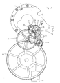
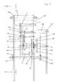
- FIGS. 1 and 2 One recognizes a drive wheel 20, which is in operative connection with the hour hand of the watch, and a minute wheel 21.
- the drive wheel 20 becomes, as in FIG FIGS. 1 and 2 indicated by means of a weight 22 driven.
- FIG. 1 It contains a partial view of a removable timer module 4. It can recognize a driven by the clock drive small ground 12, which cooperates via a coil spring, not shown, with a Kleinêtrad 23. A second wheel 24 acts as a transmission gear on a Hemmungsrad 25, which cooperates with a balance, not shown, and a not shown Hemmorgan such as armature, spring. To transfer the drive from the minute wheel 21 to the retail drive 12, an intermediate clutch wheel 72 is used.
- the auxiliary inhibition consists of a transmission gear 27 and a windscreen 28. The auxiliary inhibition is always switched by moving the movable coupling wheel 75 when the timer module 4 is removed from the movement, so that an uncontrolled and destructive rapid sequence of the movement can be advantageously avoided.
- the timer module 4 taken out. It can be seen the fixed coupling wheel 72 which is mounted on a fixed Kupplungsradwelle 73 and cooperates with the movable coupling wheel 75 and its movable Kupplungsradwelle 76.
- the movable Kupplungsradwelle 76 is mounted on a shift lever 77 which is pivotable in the direction of arrow 26 and during pivoting the movable Kupplungsradwelle 76 together with the movable Clutch wheel 75 shifts.
- the pivoting of the shift lever 77 is effected by means of a cam disk designed as a clutch disk 61, at the peripheral surface of which the free end 78 of the shift lever 77 bears under spring tension.
- the clutch disc 61 has at its periphery two radial recesses, which are arranged at a distance of 180 degrees to each other.
- the end 78 of the shift lever 77 is located at a position of the peripheral surface of the clutch disc 61, in which the shift lever 77 is pressed down.
- the movable coupling wheel 75 comes into engagement with the drive wheel 133 of the auxiliary inhibition.
- the clutch disc 61 can be rotated counterclockwise only, however, a locking device described below prevents the clutch disc 61 from rotating as long as the timer module 4 is not inserted in the movement.
- FIG. 4 one recognizes the timer module inserted into the movement 4, which is axially inserted into a circular section of a module mounting base plate 1 and then rotated counterclockwise until the radially projecting lugs 5 and 9 of the timer module 4 rest in the direction of rotation of a stopper 2.
- module bracket cover plate 3 covers the noses 5, 6, 8, 9; so that the timer module 4 is locked in the axial direction.
- the locking device preventing rotation of the clutch disc 61 must be unlocked. This is also done as a result of the timer module 4 rotating in the counterclockwise direction, with a lug 6 of the timer module 4 actuating a module lock lever 53 which is thereby rotated clockwise about a module lock lever shaft 55.
- a securing arm 54 To the same shaft 55 and a securing arm 54 is rotatable, which is rotatably connected to the module securing lever 53 and forms with this a two-armed lever. In the said movement, the free end of the securing arm 54 is disengaged from a securing lug 11, which is designed as a radial projection on a module securing disk 57.
- the module securing disc 57 can now be rotated clockwise, whereby the mechanism also causes the rotation of the clutch disc 61 counterclockwise until the free end 78 of the shift lever 77 engages in the radial recess on the circumference of the clutch disc 61 , In this case, the shift lever 77 is pivoted upward and the pivoted with movable clutch gear 75 comes out of engagement with the drive wheel 133 of the auxiliary inhibition, which is thereby deactivated.
- the module lock washer 57 is seated on a module latching shaft 58, by which it is non-rotatably connected to a module pawl disk 56 mounted on the same module latching shaft 58. During the rotation of the module securing disk 57 with the aid of the switching mechanism, the module pawl disk 56 is thus simultaneously rotated in the clockwise direction.
- the modular pawl disc 56 serves as a cam for controlling a pawl shift arm 51 which resiliently abuts under spring tension on the radially outer peripheral surface of the pawl disc 56.
- the modular pawl disc 56 has two radially projecting and with respect to the Modulrastungswelle 58 opposite sectors arranged on, which pass into two also oppositely disposed, radially recessed sectors whose angular range is about twice as large as that of the radially projecting sectors.
- the pawl shift arm 51 is rotatably disposed about a pawl shaft 52.
- pawl 50 is arranged to the same pawl shaft 52.
- switching position of the Sperrklinkenschaltarm 51 is pivoted by the radially projecting sector of the pawl disc 56 counterclockwise, the free end of the pawl 50 pivots in the region of the timer module 4 and comes to rest adjacent to a radial projection 10 of the timer module 4.
- the pawl 50 thus prevents rotation of the timer module 4 in a clockwise direction, so that it can not be removed from the clockwork in the switching state shown. This prevents in particular that the retail drive 12 is disengaged from the fixed coupling wheel 72, which would result in a destructive, rapid running of the movement.
- FIG. 7 one recognizes the modular pawl disc 56, which cooperates with the pawl switching arm 51, as well as the module pawl disc 56 rotatably connected to the module securing disc 57, which cooperates with the securing arm 54.
- the safety arm 54 is rotatably connected via the module securing lever shaft 55 to the module securing lever 53, while the pawl switching arm 51 is rotatably connected via the pawl shaft 52 with the pawl 50.
- Module pawl disk 56 and module securing disk 57 are in turn rotatably connected via the module latching shaft 58 to a disk wheel 59 for the module latching.
- ratchet wheel 66 for the module lock, reversing wheel 63 and disk wheel 59 is in a plan view in FIG. 5 shown.
- a Wegtsperrrad 67 which cooperates with a pawl 69 which acts by means of a pawl spring 70 radially from outside to inside of the Wegtsperrrad, such that rotation of the Wegradwelle 13 and thus the Heidelbergrades 66 is prevented counterclockwise.
- the clockwise rotation takes place in the illustrated movement by means of a hand crank, not shown, which is arranged in the region of the clock face, not shown, of the movement.
- a key or a knurled knob can also be provided.
- the supporting frame for all the above components of three boards is formed, namely a dial-side board 156, a middle board 157 and a rear board 158, which are each arranged by various pillars at a distance from each other and firmly connected.
- a pillar 151 which connects the dial-side board 156 with the middle board 157
- a pillar 152 which connects the middle board 157 with the rear board 158.
Landscapes
- Physics & Mathematics (AREA)
- General Physics & Mathematics (AREA)
- Astronomy & Astrophysics (AREA)
- Measurement Of Predetermined Time Intervals (AREA)
- Electric Clocks (AREA)
- Measurement Of Unknown Time Intervals (AREA)
- Magnetic Heads (AREA)
- Electromechanical Clocks (AREA)
Description
- Die Erfindung betrifft ein Uhrwerk, dessen Bauteile in Funktionsgruppen zusammenwirken.
- Insbesondere bei mechanischen Uhrwerken lassen sich verschiedene Funktionsgruppen definieren. Eine Funktionsgruppe könnte beispielsweise in einem Antriebsmotor gesehen werden, der seine Energie aus einem Energiespeicher bezieht. Als Energiespeicher kommen beispielsweise ein Federspeicher, ein Antriebsgewicht oder eine elektrische Batterie in Frage. Ein anderes Modul des Uhrwerks könnte in dem Räderwerk gesehen werden, welches die Funktion eines Übersetzungsgetriebes aufweist und zum Antrieb verschiedener Zeiger der Uhr dient. Als Modul könnte des weiteren auch das Zifferblatt mit verschiedenen Skalen für die verschiedenen Zeiger betrachtet werden. Ein weiteres Modul kann in einer den genauen Lauf des Uhrwerks bestimmenden Hemmung gesehen werden, die beispielsweise in der Form eines Pendels, eines Windfangs oder einer Unruh ausgestaltet ist. Je nach Erfordernis der Anwendung kann ein solches Zeitgebermodul auch einen Teil des Räderwerks umfassen, insbesondere wenn die einbezogenen Räder allein als Übersetzungsgetriebe für die Hemmung und nicht für andere Funktionen des Uhrwerks vorgesehen sind. Bei komplexeren Uhrwerken könnten auch die den Funktionen eines Kalenders, einer Mondphasen- oder Meerestiden-Anzeige, eines Schlagwerks oder einer Stoppuhr zugeordneten Bauteile jeweils in einem Modul zusammengefasst werden.
- Als nächstkommender Stand der Technik wird die Patentschrift
US 230,262 A vom 20.06.1880 angesehen. Hierin ist ein mechanisches Uhrwerk offenbart, bei dem das die Hemmung beinhaltende Zeitgebermodul aus dem Uhrwerk herausnehmbar ausgestaltet ist. Nach dem Herausnehmen bleibt das Zeitgebermodul jedoch stehen, da eine Wirkverbindung zu einem Antriebsmodul unterbrochen ist. - Bei bekannten Uhrwerken tritt das Problem auf, dass im Rahmen von Reparatur- oder Servicearbeiten, beispielsweise bei der Reinigung, das gesamte Uhrwerk zerlegt werden muss, um an bestimmte Teile heranzukommen. Wenn nur ein einziges kleines Bauteil ausgetauscht werden soll, muss hierfür in der Regel das Uhrwerk komplett zerlegt und anschließend wieder zusammengebaut werden. Dies ist mit erheblichen Kosten verbunden.
- Aufgabe der Erfindung ist es, ein Uhrwerk der eingangs genannten Art hinsichtlich des erforderlichen Serviceaufwandes zu verbessern.
- Die erfindungsgemäße Lösung besteht darin, dass das Zeitgebermodul einen Hilfsantrieb aufweist, der den Lauf des Zeitgebermoduls außerhalb des Uhrwerks für einen begrenzten Zeitraum aufrecht erhält. Am herausgenommenen Zeitgebermodul können sodann Servicemaßnahmen, wie Reinigung, Reparatur oder Austausch einzelner Bauteile vorgenommen werden, ohne dass das gesamte Uhrwerk zerlegt und wieder zusammengebaut und das Zeitgebermodul wieder mühsam nachjustiert werden müsste. Im schlimmsten Fall braucht nur das Servicemodul selbst zerlegt und wieder zusammengebaut werden. Da außerdem die meisten Service- und Reparaturarbeiten im Zusammenhang mit der Hemmung für die Zeitmessung anfallen, ergibt sich insgesamt eine wesentliche Verbesserung der Servicefreundlichkeit.
- Darüberhinaus bietet das erfindungsgemäße Uhrwerk die Möglichkeit, vor Ort ein defektes oder zu wartendes Zeitgebermodul durch ein anderes auszutauschen, so dass das erfindungsgemäße Uhrwerk seine Funktion ohne wesentliche Unterbrechung erfüllen kann. Das entnommene Zeitgebermodul kann dann in aller Ruhe in der Uhrmacherwerkstatt instand gesetzt werden, um anschließend in einer Rücktauschaktion wieder an seinen alten Platz zu gelangen oder bei Bedarf gegen ein reparaturbedürftiges Zeitgebermodul eines kompatiblen dritten Uhrwerks ausgetauscht zu werden.
- Die Erfindung bietet darüber hinaus die Möglichkeit, ein Zeitgebermodul durch ein passendes anderes Zeitgebermodul mit verbesserter oder unterschiedlicher Funktionsweise auszutauschen. Das andere Zeitgebermodul könnte beispielsweise eine hochwertigere oder nach einem anderen Funktionsprinzip arbeitende Hemmung enthalten. Dieser Aspekt käme insbesondere im Zusammenhang mit sehr hochwertigen Uhrwerken für Liebhaber zum Tragen. Für diese spielen ästhetische und/oder technische Aspekte des Uhrwerks eine herausragende Rolle. Deshalb hat die Erfindung diesbezüglich noch den besonderen Vorteil, dass man an dem herausgenommenen Zeitgebermodul dessen technische Funktion ganz besonders gut betrachten beziehungsweise begreifen kann und sich der Betrachter an der Schönheit des Uhrwerks und dessen Lauf erfreuen kann:
- Um dem Betrachter auch bei herausgenommenem Zeitgebermodul die technischen Funktionen und ästhetischen Aspekte des Zusammenspiels der einzelnen Bauelemente im normalen Bewegungsablauf zu demonstrieren, ist mit Vorteil vorgesehen, dass das Zeitgebermodul einen Hilfsantrieb aufweist, der den Lauf des Zeitgebermoduls außerhalb des Uhrwerks für einen begrenzten Zeitraum aufrecht erhält.
- In einer bevorzugten Ausführungsform ist der Hilfsantrieb als Federantrieb ausgebildet, der dadurch noch verbessert werden kann, dass er bei dem aus dem Uhrwerk herausgenommenen Zeitgebermodul per Hand aufziehbar ist. Der Federantrieb hat den Vorteil geringer Abmessungen bei einfachem Aufbau, kann aber dann das Zeitgebermodul im allgemeinen nur für maximal einige Minuten antreiben. Um die Demonstration des Laufs des Zeitgebermoduls zu verlängern, ist der erfindungsgemäße Handaufizug von Vorteil.
- Da ein mit der Hand bedienbares Handaufzugsbauteil beim eingebauten Zeitgebermodul in der Regel stören würde, ist für den Handaufzug mit Vorteil ein Spezialwerkzeug vorgesehen, das mit einer Antriebswelle des Federantriebs in Wirkverbindung bringbar ist.
- In Weiterbildung der Erfindung wird vorgeschlagen, dass der Federantrieb bei dem in das Uhrwerk eingesetzten Zeitgebermodul durch einen Hauptantrieb des Uhrwerks aufziehbar ist. Auf diese Weise wird nicht nur der Hauptantrieb mit dem Zeitgebermodul in Wirkverbindung gebracht, sondern auch dafür gesorgt, dass der Hilfsantrieb des Zeitgebermoduls beim Herausnehmen desselben aus dem Uhrwerk sich stets im aufgezogenen Zustand befindet.
- In einer bevorzugten Ausgestaltungsform umfasst das Zeitgebermodul ein mit dem Hilfsantrieb verbundenes und mit dem Räderwerk außerhalb des Zeitgebermoduls in Eingriff bringbares Kleinbodentrieb und ein vom Hilfsantrieb angetriebenes Übersetzungsgetriebe, welches mit einer als Hemmung dienenden Unruh in Wirkverbindung steht.
- Um einen überschnellen Lauf des Uhrwerks und eine Zerstörung seiner Bauteile bei fehlendem Zeitgebermodul zu vermeiden, sieht eine Weiterbildung der Erfindung mit Vorteil vor, dass das Uhrwerk eine Hilfshemmung aufweist, die bei herausgenommenem Zeitgebermodul zum Hemmen des Hauptantriebs aktivierbar ist.
- Die Hilfshemmung kann mit Vorteil in Form eines Windfangs ausgestaltet sein, da diese Ausgestaltungsform mit relativ geringen Mehrkosten verbunden ist und die geringere Ganggenauigkeit der Hilfshemmung auch deshalb nicht entscheidend ins Gewicht fällt, da in der Regel die Hilfshemmung ihre Aufgabe nur über relativ geringe Zeiträume von wenigen Minuten erfüllen muss.
- In Ausgestaltung der Erfindung ist vorgesehen, dass das Uhrwerk einen Schaltmechanismus zum Zuschalten der Wirkverbindung zwischen der Hilfshemmung und dem zu hemmenden Uhrwerk aufweist. Das mit dem Schaltmechanismus ausgestattete Uhrwerk hat den Vorteil, dass die Hilfshemmung nur im Bedarfsfall zugeschaltet wird und nicht ständig mitläuft. Dadurch ist einerseits die Hilfshemmung einem viel geringeren Verschleiß ausgesetzt und andererseits kann die Hilfshemmung keinen negativen Einfluß auf die Ganggenauigkeit des Uhrwerks ausüben.
- In Ausgestaltung des genannten Erfindungsgedankens wird vorgeschlagen, dass der Schaltmechanismus eine als drehbare Kurvenscheibe ausgebildete Kupplungsscheibe und einen einarmigen Schalthebel aufweist, dessen freies Ende an einer radial äußeren Steuerfläche der Kupplungsscheibe anliegt und dessen anderes Ende am Uhrwerk koaxial mit einem vom Uhrwerk angetriebenen, festen Kupplungsrad mit feststehender Kupplungsradwelle angelenkt ist, und dass am Schalthebel ein vom festen Kupplungsrad angetriebenes, bewegliches Kupplungsrad mit einer zusammen mit dem Schalthebel beweglichen Kupplungsradwelle angeordnet ist, wobei das bewegliche Kupplungsrad durch Drehen der Kupplungsscheibe und in Folge des dabei verschwenkten Schalthebels mit einem Antriebsrad der Hilfshemmung in oder außer Eingriff bringbar ist. Der Schaltmechanismus kann durch Drehen an der Kupplungsscheibe betätigt werden. Dabei wird der Schalthebel verschwenkt und das bewegliche Kupplungsrad in Eingriff mit dem Antriebsrad der Hilfshemmung gebracht, wobei das bewegliche Kupplungsrad durch die Schwenkbewegung des Schalthebels mit Vorteil auf dem festen Kupplungsrad abrollt, weil die Drehachse des festen Kupplungsrades genau mit der Drehachse des Schalthebels zusammenfällt.
- In weiterer Ausgestaltung des Schaltmechanismus wird vorgeschlagen, dass dieser mittels eines handbetätigten Umschalters schaltbar ist, der vorzugsweise ein mittels Handkurbel zu betätigendes Schaltrad aufweist, welches mit der Kupplungsscheibe in Verbindung steht. Dabei wird die Handkurbel stets in dieselbe Richtung gedreht, was durch ein Sperrad gewährleistet wird, bis die jeweilige Stellung der Kupplungsscheibe für den eingekuppelten beziehungsweise ausgekuppelten Zustand erreicht ist. Selbstverständlich benötigt der die Handkurbel drehende Benutzer für diesen Zweck Sichtkontakt entweder mit der Kupplungsscheibe oder einer mit der Kupplungsscheibe in Wirkverbindung stehenden, geeigneten optischen Anzeige.
- In einer bevorzugten Ausführungsförm der Erfindung ist das Zeitgebermodul mittels einer Art Bajonettverschluss am Uhrwerk lösbar befestigt, wobei die Drehachse des Kleinbodentriebs des Zeitgebermoduls exzentrische in Bezug auf die Drehachse des Bajonettverschlusses angeordnet ist, sodass das Kleinbodentrieb durch Drehen des Zeitgebermoduls in die geschlossene Position des Bajonettverschlusses mit einem festen Kupplungsrad des Uhrwerks in Eingriff bringbar ist. Das Prinzip des Bajonettverschlusses hat den Vorteil, dass das Zeitgebermodul bezüglich seiner axialen Lage gegenüber dem Uhrwerk bereits fixiert ist, wenn es zur Verriegelung des Bajonettverschlusses gedreht wird. Dadurch kann die Drehbewegung zum Einrasten eines exzentrischen Zahnrads benutzt werden, um das auf den Hilfsantrieb des Zeitgebermoduls wirkenden Kleinbodentrieb mit dem Hauptantrieb des Uhrwerks zu kuppeln.
- Die Erfindung lässt sich noch verbessern durch die Maßnahme, dass das Uhrwerk eine erste Sperrvorrichtung umfasst, die ein Herausnehmen des Zeitgebermoduls verhindert, solange der Umschalter die Wirkverbindung zur Hilfshemmung des Uhrwerks nicht herstellt. Dadurch wird ein Zustand verhindert, bei dem das Uhrwerk weder mit der Hemmung des Zeitgebermoduls noch mit der Hilfshemmung in Verbindung steht und sich somit zerstören würde.
- In einer bevorzugten Ausführungsform der ersten Sperrvorrichtung ist vorgesehen, dass diese einen als zweiarmiger Hebel ausgestalteten Modulklinkenschaltarm umfasst, dessen erster Hebelarm als Sperrklinke und dessen zweiter Hebelarm als Sperrklinkenschaltarm ausgebildet ist, dass die Sperrklinke im gesperrten Zustand durch Anlage an einem radialen Vorsprung des mittels Bajonettverschluss am Uhrwerk zu befestigenden Zeitgebermoduls ein Verdrehen und somit ein Herausnehmen des Zeitgebermoduls verhindert, und dass der Sperrklinkenschaftarm mit einer als Kurvenscheibe ausgestalteten Modulklinkenscheibe in Wirkverbindung steht.
- Besonders vorteilhaft ist die Maßnahme, dass die Modulklinkenscheibe mit dem Schaltmechanismus in Wirkverbindung steht, denn somit kann die Drehbewegung des Schaltmechanismus auf einfache Weise auf die Modulklinkenscheibe übertragen und der Schaltmechanismus gleichzeitig zum Sperren beziehungsweise Entsperren der ersten Sperrvorrichtung verwendet werden.
- Eine weitere vorteilhafte Sicherungsmaßnahme besteht darin, dass das Uhrwerk eine zweite Sperrvorrichtung umfasst, die ein Umschalten des Schaltmechanismus verhindert, solange das Zeitgebermodul nicht korrekt eingesetzt ist. Auf diese Weise wird verhindert, dass die Hilfshemmung außer Eingriff mit dem Uhrwerk gebracht wird, bevor nicht die Hemmung des Zeitgebermoduls in Eingriff mit dem Uhrwerk steht. Andernfalls wäre das Uhrwerk mit keiner Hemmung in Wirkverbindung und könnte sich selbst zerstören.
- In vorteilhafter Ausgestaltung der zweiten Sperrvorrichtung ist vorgesehen, dass diese einen zweiarmigen Modulsicherungshebel umfasst, der von einer radial vorspringenden Nase des Zeitgebermoduls beim Schließen des Bajonettverschlusses derart verschoben wird, dass ein mit dem Modulsicherungshebel drehfest verbundener Sicherungsarm außer Eingriff mit einer radialen Sicherungsnase einer Modulsicherungsscheibe gebracht wird, welche mit dem Schaltmechanismus in Wirkverbindung steht, derart, dass bei Eingriff des Modulsicherungshebels in die Modulsicherungsscheibe ein Umschalten des Schaltmechanismus blockiert ist.
- In einer einfachen Ausgestaltung wird die Wirkverbindung zwischen Modulsicherungsscheibe und Modulklinkenscheibe mit Vorteil dadurch erreicht; dass die Modulsicherungsscheibe mit der Modulklinkenscheibe drehfest verbunden ist.
- Wenn das Zeitgebermodul im Bereich eines Ziffernblattes des Uhrwerks einsetzbar und entnehmbar ist, kann es vom Benutzer in einfacher und bequemer Weise entnommen werden, ohne dass das Uhrwerk aus dem Uhrgehäuse ausgebaut werden müsste.
- Ein im Bereich des Ziffernblattes eingebautes Zeitgebermodul kann allerdings nur dann herausgenommen werden, wenn es nicht durch einen Zeiger der Uhr verdeckt wird. Dies betrifft insbesondere den großen Minutenzeiger. Zwar könnte man den Minutenzeiger einfach per Hand aus dem Bereich des Zeitgebermoduls herausdrehen, müsste dann aber nach dem Wiedereinsetzen des Zeitgebermoduls die genaue Uhrzeit neu einstellen. Um die letztgenannte Einstellung überflüssig zu machen, sieht eine Weiterbildung der Erfindung vor, dass ein Minutenzeiger aus dem Bereich des Zeitgebermoduls im Uhrzeigersinn herausschwenkbar ist, wobei die korrekte Minutenanzeige nach dem Hineinschwenken von selbst wieder hergestellt wird. Beim Herausschwenken des Minutenzeigers läuft das Uhrwerk weiter, sodass sich die Stellung des Minutenzeigers nach seinem Hineinschwenken in nichts von der Stellung unterscheidet, die dieser ohne das Herausschwenken eingenommen hätte. Diese Eigenschaft ist auch beim Aufziehen der Uhr von Vorteil. Wenn der Zeiger direkt vor dem Aufzugsvierkant steht, kann er im Uhrzeigersinn weitergedreht werden, ohne dass danach die Uhrzeit neu eingestellt werden müsste.
- In einer bevorzugten Ausgestaltungsform des verschwenkbaren Minutenzeigers ist ein verkürzter Hilfszeiger vorgesehen, der mit einer Zeigerwelle drehfest verbunden ist oder zumindest in relativ starkem Reibeingriff steht, und der dem mit der Zeigerwelle in relativ schwachen Reibeingriff stehenden Hauptzeiger als Anschlag in Drehrichtung dient. Somit kann der Hauptzeiger entgegen der Anschlagrichtung aus dem Bereich des Zeitgebermoduls herausgedreht werden, ohne die Stellung des Hilfszeigers zu verändern. Nach dem Wiedereinsetzen des Zeitgebermoduls wird der Hauptzeiger zunächst in seiner momentanen Position stehen bleiben, bis er vom Hilfszeiger eingeholt worden ist und am Hilfszeiger anschlägt und somit wieder seine korrekte Stellung einnimmt, die dem momentanen Zeitpunkt entspricht.
- In einer abgewandelten Ausführungsform könnte man auch einen mit der Zeigerwelle in Eingriff stehenden, verkürzten Hilfszeiger vorsehen, der mit einem frei drehbaren Hauptzeiger kuppelbar ist, beispielsweise durch eine Magnetkupplung.
- Obwohl sich die ausführlich beschriebenen Ausgestaltungsmöglichkeiten der Erfindung fast ausschließlich mit Ausführungsbeispielen und Varianten eines Zeitgebermoduls befassen, umfasst die Erfindung auch Uhrwerke mit anderen herausnehmbaren Modulen für andere technische Funktionen.
- Insbesondere kann das erfindungsgemäße Uhrwerk dadurch verbessert werden, dass es ein herausnehmbares Kalendermodul zur Darstellung der Kalendertage umfasst. Als vorteilhafte Verbesserung wäre auch ein herausnehmbares Mondphasenmodul zur Darstellung der Mondphasen und/oder der Meerestide in Betracht zu ziehen. Ohne Anspruch der Vollständigkeit sei schließlich auch auf die Möglichkeit eines herausnehmbaren Schlagwerkmoduls zur akustischen Darstellung bestimmter Zeitpunkte hingewiesen. Selbstverständlich kann ein solches Schlagwerkmodul auch optische Effekte umfassen, die zu vorbestimmten Zeitpunkten ablaufen beziehungsweise zur Anzeige gebracht werden.
- Ein Ausführungsbeispiel der Erfindung wird nachfolgend anhand der Zeichnungen näher erläutert. Die Figuren zeigen im einzelnen:
- Fig. 1:
- Eine Teilansicht eines erfindungsgemäßen Uhrwerks mit eingesetztem Zeitgebermodul;
- Fig. 2:
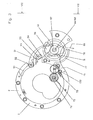
- eine andere Teilansicht desselben Uhrwerks mit einer Darstellung des Räderwerks für eine Hilfshemmung;
- Fig. 3:
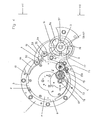
- eine weitere Teilansicht des erfindungsgemäßen Uhrwerks mit zugeschalteter Hilfshemmung und herausgenommenem Zeitgebermodul;
- Fig. 4:
- eine Ansicht entsprechend
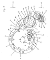
Figur 3 , jedoch mit eingesetztem Zeitgebermodul und abgeschalteter Hilfshemmung; - Fig. 5:
- eine Teilansicht desselben Uhrwerks im gleichen Zustand wie
Figur 4 mit Details des Schaltmechanismus; - Fig. 6:
- wie
Figur 5 , jedoch mit anderen Details des Schaltmechanismus; - Fig. 7:
- eine Seitenansicht desselben Uhrwerks entsprechend der in den
Figuren 4 bis 6 mit VII bezeichneten Blickrichtung. - In den
Figuren 1 und2 erkennt man ein mit dem Stundenzeiger der Uhr in Wirkverbindung stehendes Antriebsrad 20 und ein Minutenrad 21. Das Antriebsrad 20 wird wie inFiguren 1 und2 angedeutet mittels eines Gewichtes 22 angetrieben. -
Figur 1 enthält eine Teilansicht eines herausnehmbaren Zeitgebermoduls 4. Darin erkennt man ein vom Uhrwerk anzutreibendes Kleinbodentrieb 12, das über eine nicht gezeigte Spiralfeder mit einem Kleinbodenrad 23 zusammenwirkt. Ein Sekundenrad 24 wirkt als Übersetzungsgetriebe auf ein Hemmungsrad 25 ein, welches mit einer nicht gezeigten Unruh und einem nicht gezeigten Hemmorgan wie zum Beispiel Anker, Feder zusammenwirkt. Zur Übertragüng des Antriebs vom Minutenrad 21 auf das Kleinbodentrieb 12 dient ein zwischengeschaltetes Kupplungsrad 72. - Wie man in
Figur 2 erkennt, wirkt das feste Kupplungsrad 72 auf ein bewegliches Kupplungsrad 75 ein, welches im Gegensatz zum festen Kupplungsrad 72 so angeordnet ist, dass seine Drehachse entsprechend der Pfeilrichtung 26 verschoben werden kann. Dadurch ist es möglich, das bewegliche Kupplungsrad 75 entweder in oder außer Eingriff mit dem Räderwerk 27 einer Hilfshemmung zu bringen. Die Hilfshemmung besteht aus einem Übersetzungsgetriebe 27 und einem Windfang 28. Die Hilfshemmung wird durch Verschieben des beweglichen Kupplungsrades 75 immer dann zugeschaltet, wenn das Zeitgebermodul 4 aus dem Uhrwerk entfernt wird, sodass ein unkontrollierter und zerstörerischer Schnellablauf des Uhrwerks mit Vorteil vermieden werden kann. - Anhand der
Figuren 3 bis 7 wird der Zuschaltmechanismus für die Hilfshemmung und zwei Sicherungsmechanismen näher erläutert. - In der Darstellung von
Figur 3 ist das Zeitgebermodul 4 herausgenommen. Man erkennt das feste Kupplungsrad 72, welches auf einer festen Kupplungsradwelle 73 montiert ist und mit dem beweglichen Kupplungsrad 75 und seiner beweglichen Kupplungsradwelle 76 zusammenwirkt. Die bewegliche Kupplungsradwelle 76 ist auf einem Schalthebel 77 befestigt, der in Pfeilrichtung 26 verschwenkbar ist und beim Verschwenken die bewegliche Kupplungsradwelle 76 zusammen mit dem beweglichen Kupplungsrad 75 verschiebt. Die Verschwenkung des Schalthebels 77 erfolgt mittels einer als Kurvenscheibe ausgebildeten Kupplungsscheibe 61, an deren Umfangsfläche das freie Ende 78 des Schalthebels 77 unter Federspannung anliegt. Die Kupplungsscheibe 61 hat an ihrem Umfang zwei radiale Vertiefungen, die im Abstand von 180 Grad zueinander angeordnet sind. - Bei dem in
Figur 3 gezeigten Schaltzustand liegt das Ende 78 des Schalthebels 77 an einer Stelle der Umfangsfläche der Kupplungsscheibe 61 an, in der der Schalthebel 77 nach unten gedrückt wird. Dabei kommt das bewegliche Kupplungsrad 75 in Eingriff mit dem Antriebsrad 133 der Hilfshemmung. Wie sich aus der nachfolgenden Beschreibung noch ergeben wird, lässt sich die Kupplungsscheibe 61 nur entgegen dem Uhrzeigersinn drehen, wobei jedoch eine im folgenden beschriebene Sperrvorrichtung ein Drehen der Kupplungsscheibe 61 verhindert, solange das Zeitgebermodul 4 nicht in das Uhrwerk eingesetzt ist. - In
Figur 4 erkennt man das in das Uhrwerk eingesetzte Zeitgebermodul 4, welches in einen kreisförmigen Ausschnitt einer Modulhalterungsgrundplatte 1 axial eingeschoben und sodann entgegen dem Uhrzeigersinn gedreht wird, bis die radial vorspringenden Nasen 5 und 9 des Zeitgebermoduls 4 in Drehrichtung an einem Anschlag 2 anliegen. Eine wegen der Übersichtlichkeit inFigur 4 nicht eingezeichnete, jedoch inFigur 7 dargestellte Modulhalterungsdeckplatte 3 überdeckt dabei die Nasen 5, 6, 8, 9; sodass das Zeitgebermodul 4 in axialer Richtung arretiert ist. Beim Drehen des Zeitgebermoduls 4 entgegen dem Uhrzeigersinn während des Einsetzens in das Uhrwerk kommt das Kleinbodentrieb 12 in Eingriff mit dem festen Kupplungsrad 72, sodass nunmehr die Hemmung des Zeitgebermoduls 4 mit dem übrigen Uhrwerk verbunden und wirksam ist. Die Hilfshemmung 27, 28 ist jetzt nicht mehr nötig und kann abgeschaltet werden. Um die Abschaltung zu ermöglichen, muss die eine Drehung der Kupplungsscheibe 61 verhindernde Sperrvorrichtung entsperrt werden. Dies geschieht ebenfalls infolge der Drehung des Zeitgebermoduls 4 entgegen dem Uhrzeigersinn, wobei eine Nase 6 des Zeitgebermoduls 4 einen Modulsicherungshebel 53 betätigt, der dadurch um eine Modulsicherungshebelwelle 55 im Uhrzeigersinn gedreht wird. Um dieselbe Welle 55 ist auch ein Sicherungsarm 54 drehbar, der mit dem Modulsicherungshebel 53 drehfest verbunden ist und mit diesem einen zweiarmigen Hebel bildet. Bei der genannten Bewegung kommt das freie Ende des Sicherungsarms 54 außer Eingriff mit einer Sicherungsnase 11, die als radialer Vorsprung an einer Modulsicherungsscheibe 57 ausgebildet ist. Durch einen nachfolgend noch näher zu beschreibenden Schaltmechanismus kann nun die Modulsicherungsscheibe 57 im Uhrzeigersinn gedreht werden, wodurch der Mechanismus auch die Drehung der Kupplungsscheibe 61 entgegen dem Uhrzeigersinn bewirkt, bis das freie Ende 78 des Schalthebels 77 in die radiale Ausnehmung am Umfang der Kupplungsscheibe 61 einrastet. Dabei wird der Schalthebel 77 nach oben geschwenkt und das mit verschwenkte bewegliche Kupplungsrad 75 kommt außer Eingriff mit dem Antriebsrad 133 der Hilfshemmung, welche dadurch deaktiviert wird. - Die Modulsicherungsscheibe 57 sitzt auf einer Modulrastungswelle 58, durch die sie drehfest mit einer auf derselben Modulrastungswelle 58 angebrachten Modulklinkenscheibe 56 verbunden ist. Bei der Drehung der Modulsicherungsscheibe 57 mit Hilfe des Schaltmechanismus wird somit gleichzeitig die Modulklinkenscheibe 56 im Uhrzeigersinn gedreht. Die Modulklinkenscheibe 56 dient als Kurvenscheibe zur Steuerung eines Sperrklinkenschaltarms 51, der unter Federspannung an der radial äußeren Umfangsfläche der Modulklinkenscheibe 56 federnd anliegt. Die Modulklinkenscheibe 56 weist zwei radial vorspringende und in Bezug auf die Modulrastungswelle 58 gegenüber liegend angeordnete Sektoren auf, die in zwei ebenfalls gegenüber liegend angeordnete, radial zurückspringende Sektoren übergehen, deren Winkelbereich etwa doppelt so groß ist wie der der radial vorspringenden Sektoren.
- Der Sperrklinkenschaltarm 51 ist um eine Sperrklinkenwelle 52 drehbar angeordnet. Um dieselbe Sperrklinkenwelle 52 ist eine mit dem Sperrklinkenschaltarm 51 drehfest verbundene Sperrklinke 50 angeordnet. In der in
Figur 4 gezeigten Schaltstellung wird der Sperrklinkenschaltarm 51 durch den radial vorspringenden Sektor der Modulklinkenscheibe 56 entgegen dem Uhrzeigersinn verschwenkt, wobei das freie Ende der Sperrklinke 50 in den Bereich des Zeitgebermoduls 4 schwenkt und angrenzend an einen radialen Vorsprung 10 des Zeitgebermoduls 4 zu liegen kommt. Die Sperrklinke 50 verhindert somit ein Verdrehen des Zeitgebermoduls 4 im Uhrzeigersinn, sodass dieses im gezeigten Schaltzustand aus dem Uhrwerk nicht entfernt werden kann. Dadurch wird insbesondere verhindert, dass das Kleinbodentrieb 12 außer Eingriff mit dem festen Kupplungsrad 72 kommt, was ein zerstörerisch schnelles Ablaufen des Uhrwerks zur Folge hätte. - In
Figur 7 erkennt man die Modulklinkenscheibe 56, welche mit dem Sperrklinkenschaltarm 51 zusammenwirkt, sowie die mit der Modulklinkenscheibe 56 drehfest verbundene Modulsicherungsscheibe 57, welche mit dem Sicherungsarm 54 zusammenwirkt. Der Sicherungsarm 54 ist über die Modulsicherungshebelwelle 55 drehfest verbunden mit dem Modulsicherungshebel 53, während der Sperrklinkenschaltarm 51 über die Sperrklinkenwelle 52 mit der Sperrklinke 50 drehfest verbunden ist. Modulklinkenscheibe 56 und Modulsicherungsscheibe 57 sind über die Modulrastungswelle 58 wiederum drehfest verbunden mit einem Scheibenrad 59 für die Modulrastung. Unter Zwischenschaltung eines auf einer Umkehrradwelle 64 angebrachten Umkehrrades 63 ist das Scheibenrad 59 mit einem Schaltrad 66 für die Modulrastung verbunden, welches auf einer Schaltradwelle 13 angeordnet ist. Die Schaltradwelle 13 wird bei der Betätigung des Schaltmechanismus im Uhrzeigersinn gedreht, wobei das Umkehrrad 63 dafür sorgt, dass sich auch das Scheibenrad 59 für die Modulrastung zusammen mit der Modulklinkenscheibe 56 und der Modulsicherungsscheibe 57 im Uhrzeigersinn dreht. - Das Zusammenwirken von Schaltrad 66 für die Modulrastung, Umkehrrad 63 sowie Scheibenrad 59 ist in einer Draufsicht in
Figur 5 dargestellt. InFigur 5 erkennt man auch ein Schaltsperrrad 67, welches mit einer Schaltklinke 69, die mittels einer Schaltklinkenfeder 70 radial von außen nach innen auf das Schaltsperrrad einwirkt, derart zusammenwirkt, dass ein Drehen der Schaltradwelle 13 und damit des Schaltrades 66 entgegen dem Uhrzeigersinn verhindert wird. Die Drehung im Uhrzeigersinn erfolgt bei dem dargestellten Uhrwerk mittels einer nicht gezeigten Handkurbel, die im Bereich des nicht gezeigten Ziffernblatts des Uhrwerks angeordnet ist. Statt der Handkurbel kann auch ein Schlüssel oder ein Rändelknopf vorgesehen sein. - Wie man am besten in
Figur 7 erkennt, ist auf der Schaltradwelle 13 auch ein Schaltrad 65 für die Räderwerkkupplung angebracht, welches sich bei Betätigung der Schaltradwelle 13 zusammen mit dieser im Uhrzeigersinn dreht. Das Schaltrad 65 steht in Eingriff mit einem Scheibenrad 60 für die Räderwerkkupplung, welches mittels einer Räderwerkkupplungswelle 62 drehfest mit der Kupplungsscheibe 61 verbunden ist. Wenn die Schaftradwelle 13 zusammen mit dem Schaltrad 65 im Uhrzeigersinn gedreht wird, dreht sich das Scheibenrad 60 zusammen mit der Kupplungsscheibe 61 entgegen dem Uhrzeigersinn. Das Zusammenwirken von Schaltradwelle 13, Schaltrad 65 und Scheibenrad 60 für die Räderwerkkupplung sowie der Kupplungsscheibe 61 ist in der Draufsicht vonFigur 6 ebenfalls zu erkennen. - Wie man ebenfalls in
Figur 7 erkennt, wird der stützende Rahmen für alle vorbeschriebenen Bauteile von drei Platinen gebildet, nämlich einer zifferblattseitigen Platine 156, einer mittleren Platine 157 und einer hinteren Platine 158, die jeweils durch diverse Pfeiler im Abstand zueinander angeordnet und fest verbunden sind. Insbesondere erkennt man inFigur 7 einen Pfeiler 151, der die zifferblattseitige Platine 156 mit der mittleren Platine 157 verbindet und einen Pfeiler 152, der die mittlere Platine 157 mit der hinteren Platine 158 verbindet. Weiterhin erkennt man einen Modulhalterungspfeiler 7, der neben anderen die Modulhalterungsgrundplatte 1 mit der mittleren Platine 157 verbindet. -
- 1
- Modulhalterungsgrundplatte
- 2
- Anschlag
- 3
- Modulhalterungsdeckplatte
- 4
- Zeitgebermodul
- 5
- Nase
- 6
- Nase
- 7
- Modulhalterungspfeiler
- 8
- Nase
- 9
- Nase
- 10
- radialer Vorsprung
- 11
- Sicherungsnase
- 12
- Kleinbodentrieb
- 13
- Schaltradwelle
- 20
- Antriebsrad
- 21
- Minutenrad und Trieb
- 22
- Antriebsgewicht
- 23
- Kleinbodenrad mit Hilfsantrieb
- 24
- Sekundenrad und Trieb
- 25
- Hemmungsrad und Trieb
- 26
- Pfeilrichtung
- 27
- Übersetzungsgetriebe
- 28
- Windfang mit Trieb
- 50
- sperrklinke
- 51
- Sperrklinkenschaltarm
- 52
- Sperrklinkenwelle
- 53
- Modulsicherungshebel
- 54
- Sicherungsarm
- 55
- Modulsicherungshebelwelle
- 56
- Modulklinkenscheibe
- 57
- Modulsicherungsscheibe
- 58
- Modulrastungswelle
- 59
- Scheibenrad für Modulrastung
- 60
- Scheibenrad für Räderwerkkupplung
- 61
- Kupplungsscheibe
- 62
- Räderwerkkupplungswelle
- 63
- Umkehrrad für Modulrastung
- 64
- Umkehrradwelle
- 65
- Schaltrad für Räderwerkkupplung
- 66
- Schaltrad für Modulrastung
- 67
- Schaltsperrrad
- 69
- Schaltklinke
- 70
- Schaltklinkenfeder
- 72
- festes Kupplungsrad
- 73
- feste Kupplungsradwelle
- 75
- bewegliches Kupplungsrad
- 76
- bewegliche Kupplungsradwelle
- 77
- Schalthebel
- 78
- freies Ende
- 133
- Antriebsrad der Hilfshemmung
- 151
- Pfeiler
- 152
- Pfeiler
- 156
- zifferblattseitige Platine
- 157
- mittlere Platine
- 158
- hintere Platine
Claims (25)
- Uhrwerk, dessen Bauteile in Funktionsgruppen zusammenwirken, wobei mindestens eine Funktionsgruppe, die eine Hemmung für die Zeitmessung umfasst, als herausnehmbares Zeitgebermodul (4) ausgestaltet ist, dadurch gekennzeichnet, dass das Zeitgebermodul (4) einen Hilfsantrieb (23) aufweist, der so angeordnet ist, dass der Lauf des Zeitgebermoduls (4) außerhalb des Uhrwerks für einen begrenzten Zeitraum aufrecht erhalten ist
- Uhrwerk nach Anspruch 1, dadurch gekennzeichnet, dass der Hilfsantrieb (23) als Federantrieb ausgebildet ist.
- Uhrwerk nach Anspruch 2, dadurch gekennzeichnet, dass der Hilfsantrieb (23) bei dem aus dem Uhrwerk herausgenommenen Zeitgebermodul (4) per Hand aufziehbar ist.
- Uhrwerk nach Anspruch 3, dadurch gekennzeichnet, dass eine Antriebswelle (12) des Federantriebs (23) in Wirkverbindung mit einem Spezial werkzeug bringbar ist.
- Uhrwerk nach einem der Ansprüche 2 bis 4, dadurch gekennzeichnet, dass der Federantrieb (23) bei dem in das Uhrwerk eingesetzten Zeitgebermodul (4) durch einen Hauptantrieb (20, 21, 22) des Uhrwerks aufziehbar ist.
- Uhrwerk nach einem der vorhergehenden Ansprüche, dadurch gekennzeichnet, dass das Zeitgebermodul (4) ein mit dem Hilfsantrieb (23) verbundenes und mit dem Räderwerk (72) außerhalb des Zeitgebermoduls (4) in Eingriff bringbares Kleinbodentrieb (12) und ein vom Hilfsantrieb (23) angetriebenes Übersetzungsgetriebe (24, 25) umfasst, welches mit einer als Hemmung dienenden Unruh in Wirkverbindung steht.
- Uhrwerk nach einem der vorhergehenden Ansprüche, dadurch gekennzeichnet, dass es eine Hilfshemmung (27, 28) aufweist, die bei herausgenommenem Zeitgebermodul (4) zum Hemmen des Hauptantriebs (20, 21, 22) aktivierbar ist.
- Uhrwerk nach Anspruch 7. dadurch gekennzeichnet, dass die Hilfshemmung (27, 28) einen Windfang (28) aufweist.
- Uhrwerk nach Anspruch 7 oder 8, dadurch gekennzeichnet, dass es einen Schaltmechanismus (13, 65, 60, 61, 77) zum Zuschalten der Wirkverbindung zwischen der Hilfshemmung (27, 28) und dem zu hemmenden Uhrwerk aufweist.
- Uhrwerk nach Anspruch 9, dadurch gekennzeichnet, dass der Schaltmechanismus eine als drehbare Kurvenscheibe ausgebildete Kupplungsscheibe (61) und einen einarmigen Schalthebel (77) aufweist, dessen freies Ende (78) an einer radial äußeren Steuerfläche der Kupplungsscheibe (61) und dessen anderes Ende am Uhrwerk koaxial mit einem vom Uhrwerk angetriebenen festen Kupplungsrad (72) mit feststehender Küpplungsradwelle (73) angelenkt ist, und dass am Schalthebel (77) ein vom festen Kupplungsrad (72) angetriebenes, bewegliches Kupplungsrad (75) mit einer zusammen mit dem Schalthebel (77) beweglichen Kuppnngsradwelle (76) angeordnet ist, wobei das bewegliche Kupplungsrad (75) durch Drehen der Kupplungsscheibe (61) und in Folge des dabei verschwenkten Schalthebels (77) mit einem Antriebsrad (133) der Hilfshemmung in oder außer Eingriff bringbar ist.
- Uhrwerk nach Anspruch 9 oder 10, dadurch gekennzeichnet, dass der Schaltmechanismus mittels eines handbetätigten Umschalters schaltbar ist, der vorzugsweise ein mittels Handkurbel oder Schlüssel oder Rändelknopf zu betätigendes Schaltrad (65) aufweist, welches mit der Kupplungsscheibe (61) in Verbindung steht.
- Uhrwerk nach einem der Ansprüche 7 bis 11, dadurch gekennzeichnet, dass das Zeitgebermodul (4) mittels einer Art Bajonettverschluss am Uhrwerk lösbar befestigt ist und dass die Drehachse des Kleinbodentriebs (12) des Zeitgebermoduls (4) exzentrisch in Bezug auf die Drehachse des Bajonettverschlusses angeordnet ist, sodass das Kleinbodentrieb (12) durch Drehen des Zeitgebermoduls (4) in die geschlossene Position des Bajonettverschlusses mit einem festen Kupplungsrad (72) des Uhrwerks in Eingriff bringbar ist.
- Uhrwerk nach Anspruch 9 oder 10, dadurch gekennzeichnet, dass es eine erste Sperrvorrichtung umfasst, die ein Herausnehmen des Zeitgebermoduls (4) verhindert, solange der Umschalter die Wirkverbindung zur Hilfshemmung (27, 28) des Uhrwerks nicht herstellt.
- Uhrwerk nach Anspruch 11, dadurch gekennzeichnet, dass die erste Sperrvorrichtung einen als zweiarmiger Hebel ausgestalteten Modulklinkenschaltarm (51) umfasst, dessen erster Hebelarm als Sperrklinke (50) und dessen zweiter Hebelarm als Sperrklinkenschaltarm (51) ausgebildet ist, dass die Sperrklinke (50) in gesperrtem Zustand durch Anlage an einem radialen Vorsprung (10) des mittels Bajonettverschluss am Uhrwerk zu befestigenden Zeitgebermoduls (4) ein Verdrehen und somit ein Herausnehmen des Zeitgebermoduls (4) verhindert, und dass der Sperrklinkerischaltarm (51) mit einer als Kurvenscheibe ausgestalteten Modulklinkenscheibe (56) in Wirkverbindung steht.
- Uhrwerk nach Anspruch 14, dadurch gekennzeichnet, dass die Modulklinkenscheibe (56) mit dem Schaltmechanismus in Wirkverbindung steht.
- Uhrwerk nach einem der Ansprüche 9 bis 11, dadurch gekennzeichnet, dass es eine zweite Sperrvorrichtung umfasst, die ein Umschalten des Schaltmechanismus verhindert, solange das Zeitgebermodul (4) nicht korrekt eingesetzt ist.
- Uhrwerk nach Anspruch 16, dadurch gekennzeichnet, dass die zweite Sperrvorrichtung einen zweiarmigen Modulsicherungshebel (53) umfasst, der von einer radial vorspringenden Nase (6) des Zeitgebermoduls (4) beim Schließen des Bajonettverschlusses derart verschoben wird, dass ein mit dem Modulsicherungshebel (53) drehfest verbundener Sicherungsarm (54) außer Eingriff mit einer radialen Sicherungsnase (11) einer Modulsicherungsscheibe (57) gebracht wird, welche mit dem Schaltmechanismus in Wirkverbindung steht derart, dass bei Eingriff des Modulsicherungshebels (53) in die Modulsicherungsscheibe (57) ein Umschalten des Schaltmechanismus blockiert ist.
- Uhrwerk nach Anspruch 17, dadurch gekennzeichnet, dass die Modulsicherungsscheibe (57) mit der Modulklinkenscheibe (56) drehfest verbunden ist.
- Uhrwerk nach einem der vorhergehenden Ansprüche, dadurch gekennzeichnet, dass das Zeitgebermodul (4) im Bereich eines Ziffernblattes des Uhrwerks einsetzbar und entnehmbar ist.
- Uhrwerk nach Anspruch 19, dadurch gekennzeichnet, dass ein Minutenzeiger aus dem Bereich des Zeitgebermoduls (4) im Uhrzeigersinn herausdrehbar ist, wobei die korrekte Minutenanzeige danach von selbst wieder hergestellt wird.
- Uhrwerk nach Anspruch 20, dadurch gekennzeichnet, dass ein verkürzter Hilfszeiger vorgesehen ist, der mit einer Zeigerwelle drehfest verbunden ist oder zumindest in relativ starkem Reibeingriff steht und der dem mit der Zeigerwelle in relativ schwachem Reibeingriff stehenden Hauptzeiger als Anschlag in Drehrichtung dient.
- Uhrwerk nach Anspruch 20, dadurch gekennzeichnet, dass ein mit der Zeigerwelle in Eingriff stehender verkürzter Hilfszeiger mit einem frei drehbaren Hauptzeiger kuppelbar ist, beispielsweise durch eine Magnetkupplung.
- Uhrwerk nach einem der vorhergehenden Ansprüche, dadurch gekennzeichnet, dass es ein herausnehmbares Kalendermodul zur Darstellung der Kalendertage umfasst.
- Uhrwerk nach einem der vorhergehenden Ansprüche, dadurch gekennzeichnet, dass es ein herausnehmbares Mondphasenmodul zur Darstellung der Mondphasen und/oder der Meerestide aufweist.
- Uhrwerk nach einem der vorhergehenden Ansprüche, dadurch gekennzeichnet, dass es ein herausnehmbares Schlagwerkmodul zur akustischen Darstellung bestimmter Zeitpunkte aufweist.
Applications Claiming Priority (3)
| Application Number | Priority Date | Filing Date | Title |
|---|---|---|---|
| DE10309006A DE10309006A1 (de) | 2003-03-01 | 2003-03-01 | Uhrwerk |
| DE10309006 | 2003-03-01 | ||
| PCT/EP2004/001943 WO2004079460A2 (de) | 2003-03-01 | 2004-02-26 | Uhrwerk |
Publications (2)
| Publication Number | Publication Date |
|---|---|
| EP1599765A2 EP1599765A2 (de) | 2005-11-30 |
| EP1599765B1 true EP1599765B1 (de) | 2011-04-13 |
Family
ID=29432765
Family Applications (1)
| Application Number | Title | Priority Date | Filing Date |
|---|---|---|---|
| EP04714746A Expired - Lifetime EP1599765B1 (de) | 2003-03-01 | 2004-02-26 | Uhrwerk |
Country Status (4)
| Country | Link |
|---|---|
| EP (1) | EP1599765B1 (de) |
| AT (1) | ATE505754T1 (de) |
| DE (2) | DE10309006A1 (de) |
| WO (1) | WO2004079460A2 (de) |
Families Citing this family (1)
| Publication number | Priority date | Publication date | Assignee | Title |
|---|---|---|---|---|
| CN112363377B (zh) * | 2020-11-06 | 2025-06-03 | 天王电子(深圳)有限公司 | 一种手表机芯及手表 |
Family Cites Families (5)
| Publication number | Priority date | Publication date | Assignee | Title |
|---|---|---|---|---|
| US230262A (en) * | 1880-07-20 | Frederick fitt | ||
| US2393671A (en) * | 1942-10-30 | 1946-01-29 | Wolfe Lester | Timepiece regulator |
| US2501266A (en) * | 1945-12-10 | 1950-03-21 | Elgin Nat Watch Co | Marine chronometer double track escape and projection system |
| DE1995485U (de) * | 1968-02-17 | 1968-10-24 | Kieninger & Obergfell | Elektrisches uhrwerk fuer nichttragbare uhren mit kleinster leistungsaufnahme. |
| GB1470772A (en) * | 1973-06-20 | 1977-04-21 | United Gas Industries Ltd | Timing movement |
-
2003
- 2003-03-01 DE DE10309006A patent/DE10309006A1/de not_active Ceased
-
2004
- 2004-02-26 AT AT04714746T patent/ATE505754T1/de active
- 2004-02-26 DE DE502004012399T patent/DE502004012399D1/de not_active Expired - Lifetime
- 2004-02-26 EP EP04714746A patent/EP1599765B1/de not_active Expired - Lifetime
- 2004-02-26 WO PCT/EP2004/001943 patent/WO2004079460A2/de not_active Ceased
Also Published As
| Publication number | Publication date |
|---|---|
| WO2004079460A3 (de) | 2005-02-10 |
| WO2004079460A2 (de) | 2004-09-16 |
| ATE505754T1 (de) | 2011-04-15 |
| EP1599765A2 (de) | 2005-11-30 |
| DE10309006A1 (de) | 2003-12-11 |
| DE502004012399D1 (de) | 2011-05-26 |
Similar Documents
| Publication | Publication Date | Title |
|---|---|---|
| DE69000228T2 (de) | Analoganzeigeeinheit fuer ein uhrwerk. | |
| EP1546820A2 (de) | Uhr mit innerem drehbarem gehäuse | |
| DE102008000540B4 (de) | Chronograph | |
| DE2319907B2 (de) | Kalender-Schaltvorrichtung für Uhren | |
| DE68906041T2 (de) | Uhr. | |
| CH450967A (de) | Ubungshandgranate | |
| DE2936093A1 (de) | Zeitgesteuertes schloss | |
| DE2929091C3 (de) | Elektriches Zeitschlagwerk für eine Uhr | |
| DE2619298A1 (de) | Uhrmechanismus | |
| EP1599765B1 (de) | Uhrwerk | |
| DE69829486T2 (de) | Ewige kalenderuhr | |
| DE2202846A1 (de) | Zeigerstell- und unruh-anhaltevorrichtung | |
| DE1548136C3 (de) | Kalenderuhr | |
| CH704611A2 (de) | Hemmung und Kalendermechanik für eine mechanische Uhr. | |
| DE2723938C3 (de) | Elektromechanische Uhr mit Kalender | |
| DE60216277T2 (de) | Weltzeituhr mit Weckermechanismus | |
| DE1798302A1 (de) | Armbanduhr | |
| CH285529A (de) | Mehrtägige Weckeruhr. | |
| DE918255C (de) | Korrektureinrichtung fuer Nebenuhren mit Ziffernwalzen | |
| DE2621225C3 (de) | ||
| DE2141015A1 (de) | Uhrwerk für Kalenderuhr | |
| DE2400742A1 (de) | Weckeruhr | |
| DE1523778C (de) | Kalenderuhr | |
| DE2509884A1 (de) | Weckerwerk | |
| AT19199B (de) | Monatsuhr mit Einrichtung zur selbsttätigen Anzeige des notwendigen Aufziehens. |
Legal Events
| Date | Code | Title | Description |
|---|---|---|---|
| PUAI | Public reference made under article 153(3) epc to a published international application that has entered the european phase |
Free format text: ORIGINAL CODE: 0009012 |
|
| 17P | Request for examination filed |
Effective date: 20050913 |
|
| AK | Designated contracting states |
Kind code of ref document: A2 Designated state(s): AT BE BG CH CY CZ DE DK EE ES FI FR GB GR HU IE IT LI LU MC NL PT RO SE SI SK TR |
|
| AX | Request for extension of the european patent |
Extension state: AL LT LV MK |
|
| DAX | Request for extension of the european patent (deleted) | ||
| 17Q | First examination report despatched |
Effective date: 20100414 |
|
| GRAP | Despatch of communication of intention to grant a patent |
Free format text: ORIGINAL CODE: EPIDOSNIGR1 |
|
| RTI1 | Title (correction) |
Free format text: TIMEPIECE MOVEMENT |
|
| GRAS | Grant fee paid |
Free format text: ORIGINAL CODE: EPIDOSNIGR3 |
|
| GRAA | (expected) grant |
Free format text: ORIGINAL CODE: 0009210 |
|
| AK | Designated contracting states |
Kind code of ref document: B1 Designated state(s): AT BE BG CH CY CZ DE DK EE ES FI FR GB GR HU IE IT LI LU MC NL PT RO SE SI SK TR |
|
| REG | Reference to a national code |
Ref country code: GB Ref legal event code: FG4D Free format text: NOT ENGLISH |
|
| REG | Reference to a national code |
Ref country code: CH Ref legal event code: EP |
|
| REG | Reference to a national code |
Ref country code: IE Ref legal event code: FG4D Free format text: LANGUAGE OF EP DOCUMENT: GERMAN |
|
| REF | Corresponds to: |
Ref document number: 502004012399 Country of ref document: DE Date of ref document: 20110526 Kind code of ref document: P |
|
| REG | Reference to a national code |
Ref country code: DE Ref legal event code: R096 Ref document number: 502004012399 Country of ref document: DE Effective date: 20110526 |
|
| REG | Reference to a national code |
Ref country code: NL Ref legal event code: VDEP Effective date: 20110413 |
|
| REG | Reference to a national code |
Ref country code: CH Ref legal event code: NV Representative=s name: BOVARD AG |
|
| PG25 | Lapsed in a contracting state [announced via postgrant information from national office to epo] |
Ref country code: SE Free format text: LAPSE BECAUSE OF FAILURE TO SUBMIT A TRANSLATION OF THE DESCRIPTION OR TO PAY THE FEE WITHIN THE PRESCRIBED TIME-LIMIT Effective date: 20110413 Ref country code: PT Free format text: LAPSE BECAUSE OF FAILURE TO SUBMIT A TRANSLATION OF THE DESCRIPTION OR TO PAY THE FEE WITHIN THE PRESCRIBED TIME-LIMIT Effective date: 20110816 |
|
| REG | Reference to a national code |
Ref country code: IE Ref legal event code: FD4D |
|
| PG25 | Lapsed in a contracting state [announced via postgrant information from national office to epo] |
Ref country code: ES Free format text: LAPSE BECAUSE OF FAILURE TO SUBMIT A TRANSLATION OF THE DESCRIPTION OR TO PAY THE FEE WITHIN THE PRESCRIBED TIME-LIMIT Effective date: 20110724 Ref country code: CY Free format text: LAPSE BECAUSE OF FAILURE TO SUBMIT A TRANSLATION OF THE DESCRIPTION OR TO PAY THE FEE WITHIN THE PRESCRIBED TIME-LIMIT Effective date: 20110413 Ref country code: FI Free format text: LAPSE BECAUSE OF FAILURE TO SUBMIT A TRANSLATION OF THE DESCRIPTION OR TO PAY THE FEE WITHIN THE PRESCRIBED TIME-LIMIT Effective date: 20110413 Ref country code: SI Free format text: LAPSE BECAUSE OF FAILURE TO SUBMIT A TRANSLATION OF THE DESCRIPTION OR TO PAY THE FEE WITHIN THE PRESCRIBED TIME-LIMIT Effective date: 20110413 Ref country code: GR Free format text: LAPSE BECAUSE OF FAILURE TO SUBMIT A TRANSLATION OF THE DESCRIPTION OR TO PAY THE FEE WITHIN THE PRESCRIBED TIME-LIMIT Effective date: 20110714 |
|
| PG25 | Lapsed in a contracting state [announced via postgrant information from national office to epo] |
Ref country code: NL Free format text: LAPSE BECAUSE OF FAILURE TO SUBMIT A TRANSLATION OF THE DESCRIPTION OR TO PAY THE FEE WITHIN THE PRESCRIBED TIME-LIMIT Effective date: 20110413 |
|
| PG25 | Lapsed in a contracting state [announced via postgrant information from national office to epo] |
Ref country code: EE Free format text: LAPSE BECAUSE OF FAILURE TO SUBMIT A TRANSLATION OF THE DESCRIPTION OR TO PAY THE FEE WITHIN THE PRESCRIBED TIME-LIMIT Effective date: 20110413 Ref country code: IE Free format text: LAPSE BECAUSE OF FAILURE TO SUBMIT A TRANSLATION OF THE DESCRIPTION OR TO PAY THE FEE WITHIN THE PRESCRIBED TIME-LIMIT Effective date: 20110413 Ref country code: CZ Free format text: LAPSE BECAUSE OF FAILURE TO SUBMIT A TRANSLATION OF THE DESCRIPTION OR TO PAY THE FEE WITHIN THE PRESCRIBED TIME-LIMIT Effective date: 20110413 |
|
| PLBE | No opposition filed within time limit |
Free format text: ORIGINAL CODE: 0009261 |
|
| STAA | Information on the status of an ep patent application or granted ep patent |
Free format text: STATUS: NO OPPOSITION FILED WITHIN TIME LIMIT |
|
| PG25 | Lapsed in a contracting state [announced via postgrant information from national office to epo] |
Ref country code: SK Free format text: LAPSE BECAUSE OF FAILURE TO SUBMIT A TRANSLATION OF THE DESCRIPTION OR TO PAY THE FEE WITHIN THE PRESCRIBED TIME-LIMIT Effective date: 20110413 Ref country code: DK Free format text: LAPSE BECAUSE OF FAILURE TO SUBMIT A TRANSLATION OF THE DESCRIPTION OR TO PAY THE FEE WITHIN THE PRESCRIBED TIME-LIMIT Effective date: 20110413 Ref country code: RO Free format text: LAPSE BECAUSE OF FAILURE TO SUBMIT A TRANSLATION OF THE DESCRIPTION OR TO PAY THE FEE WITHIN THE PRESCRIBED TIME-LIMIT Effective date: 20110413 |
|
| 26N | No opposition filed |
Effective date: 20120116 |
|
| REG | Reference to a national code |
Ref country code: DE Ref legal event code: R097 Ref document number: 502004012399 Country of ref document: DE Effective date: 20120116 |
|
| PG25 | Lapsed in a contracting state [announced via postgrant information from national office to epo] |
Ref country code: IT Free format text: LAPSE BECAUSE OF FAILURE TO SUBMIT A TRANSLATION OF THE DESCRIPTION OR TO PAY THE FEE WITHIN THE PRESCRIBED TIME-LIMIT Effective date: 20110413 |
|
| BERE | Be: lapsed |
Owner name: FUCHS, MATTHIAS Effective date: 20120228 |
|
| PG25 | Lapsed in a contracting state [announced via postgrant information from national office to epo] |
Ref country code: MC Free format text: LAPSE BECAUSE OF NON-PAYMENT OF DUE FEES Effective date: 20120229 |
|
| REG | Reference to a national code |
Ref country code: CH Ref legal event code: PL |
|
| GBPC | Gb: european patent ceased through non-payment of renewal fee |
Effective date: 20120226 |
|
| PG25 | Lapsed in a contracting state [announced via postgrant information from national office to epo] |
Ref country code: LI Free format text: LAPSE BECAUSE OF NON-PAYMENT OF DUE FEES Effective date: 20120229 Ref country code: CH Free format text: LAPSE BECAUSE OF NON-PAYMENT OF DUE FEES Effective date: 20120229 |
|
| REG | Reference to a national code |
Ref country code: FR Ref legal event code: ST Effective date: 20121031 |
|
| REG | Reference to a national code |
Ref country code: DE Ref legal event code: R119 Ref document number: 502004012399 Country of ref document: DE Effective date: 20120901 |
|
| PG25 | Lapsed in a contracting state [announced via postgrant information from national office to epo] |
Ref country code: BE Free format text: LAPSE BECAUSE OF NON-PAYMENT OF DUE FEES Effective date: 20120228 |
|
| PG25 | Lapsed in a contracting state [announced via postgrant information from national office to epo] |
Ref country code: GB Free format text: LAPSE BECAUSE OF NON-PAYMENT OF DUE FEES Effective date: 20120226 Ref country code: FR Free format text: LAPSE BECAUSE OF NON-PAYMENT OF DUE FEES Effective date: 20120229 |
|
| REG | Reference to a national code |
Ref country code: AT Ref legal event code: MM01 Ref document number: 505754 Country of ref document: AT Kind code of ref document: T Effective date: 20120226 |
|
| PG25 | Lapsed in a contracting state [announced via postgrant information from national office to epo] |
Ref country code: AT Free format text: LAPSE BECAUSE OF NON-PAYMENT OF DUE FEES Effective date: 20120226 Ref country code: DE Free format text: LAPSE BECAUSE OF NON-PAYMENT OF DUE FEES Effective date: 20120901 Ref country code: BG Free format text: LAPSE BECAUSE OF FAILURE TO SUBMIT A TRANSLATION OF THE DESCRIPTION OR TO PAY THE FEE WITHIN THE PRESCRIBED TIME-LIMIT Effective date: 20110713 |
|
| PG25 | Lapsed in a contracting state [announced via postgrant information from national office to epo] |
Ref country code: TR Free format text: LAPSE BECAUSE OF FAILURE TO SUBMIT A TRANSLATION OF THE DESCRIPTION OR TO PAY THE FEE WITHIN THE PRESCRIBED TIME-LIMIT Effective date: 20110413 |
|
| PG25 | Lapsed in a contracting state [announced via postgrant information from national office to epo] |
Ref country code: LU Free format text: LAPSE BECAUSE OF NON-PAYMENT OF DUE FEES Effective date: 20120226 |
|
| PG25 | Lapsed in a contracting state [announced via postgrant information from national office to epo] |
Ref country code: HU Free format text: LAPSE BECAUSE OF FAILURE TO SUBMIT A TRANSLATION OF THE DESCRIPTION OR TO PAY THE FEE WITHIN THE PRESCRIBED TIME-LIMIT Effective date: 20040226 |