EP1599672B1 - Pompe pour matieres epaisses - Google Patents
Pompe pour matieres epaisses Download PDFInfo
- Publication number
- EP1599672B1 EP1599672B1 EP03775139A EP03775139A EP1599672B1 EP 1599672 B1 EP1599672 B1 EP 1599672B1 EP 03775139 A EP03775139 A EP 03775139A EP 03775139 A EP03775139 A EP 03775139A EP 1599672 B1 EP1599672 B1 EP 1599672B1
- Authority
- EP
- European Patent Office
- Prior art keywords
- thick matter
- suction
- pressure device
- pump according
- line
- Prior art date
- Legal status (The legal status is an assumption and is not a legal conclusion. Google has not performed a legal analysis and makes no representation as to the accuracy of the status listed.)
- Expired - Lifetime
Links
- 239000000463 material Substances 0.000 title description 9
- 238000005086 pumping Methods 0.000 claims description 33
- 230000006835 compression Effects 0.000 claims description 5
- 238000007906 compression Methods 0.000 claims description 5
- 239000012530 fluid Substances 0.000 abstract 1
- 238000000034 method Methods 0.000 description 14
- 239000002002 slurry Substances 0.000 description 4
- 238000012546 transfer Methods 0.000 description 3
- 230000000694 effects Effects 0.000 description 2
- 239000010802 sludge Substances 0.000 description 2
- 239000000969 carrier Substances 0.000 description 1
- 238000006243 chemical reaction Methods 0.000 description 1
- 238000004891 communication Methods 0.000 description 1
- 230000003247 decreasing effect Effects 0.000 description 1
- 230000001934 delay Effects 0.000 description 1
- 238000013461 design Methods 0.000 description 1
- 230000002349 favourable effect Effects 0.000 description 1
- 238000012423 maintenance Methods 0.000 description 1
- 238000004519 manufacturing process Methods 0.000 description 1
- 230000036316 preload Effects 0.000 description 1
- 230000010349 pulsation Effects 0.000 description 1
- 230000000717 retained effect Effects 0.000 description 1
Images


Classifications
-
- F—MECHANICAL ENGINEERING; LIGHTING; HEATING; WEAPONS; BLASTING
- F04—POSITIVE - DISPLACEMENT MACHINES FOR LIQUIDS; PUMPS FOR LIQUIDS OR ELASTIC FLUIDS
- F04B—POSITIVE-DISPLACEMENT MACHINES FOR LIQUIDS; PUMPS
- F04B15/00—Pumps adapted to handle specific fluids, e.g. by selection of specific materials for pumps or pump parts
- F04B15/02—Pumps adapted to handle specific fluids, e.g. by selection of specific materials for pumps or pump parts the fluids being viscous or non-homogeneous
- F04B15/023—Pumps adapted to handle specific fluids, e.g. by selection of specific materials for pumps or pump parts the fluids being viscous or non-homogeneous supply of fluid to the pump by gravity through a hopper, e.g. without intake valve
-
- F—MECHANICAL ENGINEERING; LIGHTING; HEATING; WEAPONS; BLASTING
- F04—POSITIVE - DISPLACEMENT MACHINES FOR LIQUIDS; PUMPS FOR LIQUIDS OR ELASTIC FLUIDS
- F04B—POSITIVE-DISPLACEMENT MACHINES FOR LIQUIDS; PUMPS
- F04B7/00—Piston machines or pumps characterised by having positively-driven valving
- F04B7/0038—Piston machines or pumps characterised by having positively-driven valving the distribution member forming a single inlet for a plurality of pumping chambers or a multiple discharge for one single pumping chamber
Definitions
- the invention relates to a slurry pump with at least two alternating pumping and suction pumping units, a delivery line, a suction line and a switching valve for switching between the two pumping units, wherein the switching valve a pump unit in pumping operation with the delivery line and a pump unit in the suction with the suction line combines.
- the characteristic of such pumps consists in the fact that at the end of a stroke, at least during the switching time of the switching valve, the pumping work is interrupted. Further delays result from the properties of the medium to be pumped. In concrete, the most pumped medium, the suction stroke can often cause insufficient filling of the cylinder. It is therefore necessary before each pushing of the flow a compression of the medium.
- a particularly negative effect, which influences the pumping process, is that during the switching process, the valve position allows a backflow of thick matter from the feed line in the not completely filled suction cylinder or even in the reservoir.
- the sludge pump has two pumping units and an auxiliary pumping unit, wherein the two pumping units can be connected via a valve alternately with a delivery line and a reservoir.
- the slurry pump is operated according to the following method: The first pump unit is connected in suction with the reservoir, the second pump unit is connected in pumping operation via the valve to the delivery line.
- the auxiliary pump unit is permanently connected to the valve and thus to the delivery line.
- the auxiliary unit conveys thick matter into the delivery line in order to maintain a constant delivery flow.
- the second pump unit is connected in suction with the reservoir.
- the auxiliary pumping unit is now also in the suction mode and sucks thick matter from the delivery line to refill.
- the two pumping units which form a two-cylinder slurry pump, and are connected by means of a change-over alternately to the container or the delivery line and the delivery piston alternately with each other perform a suction and a pressure stroke, controlled so that the average piston speed during the intake stroke is at least temporarily greater than during the compression stroke.
- the changeover device separates the two delivery cylinders at least temporarily from the storage container and connects the latter together to the delivery line.
- the one delivery piston has not yet completed its pressure stroke, but at the same time the other delivery piston also begins with its pressure stroke, wherein a delivery piston performs its suction stroke only when the short circuit substantially canceled and the associated delivery cylinder is reconnected to the container ,
- This conclusive proposal suffers, depending on the consistency of the medium to be pumped, from the fact that in case of insufficient cylinder filling a slight pulsation can occur.
- a disadvantage of this solution is only a certain amount of control, which is required to match the asynchronous movement of the drive cylinder, the slide and the boost pressure device to each other so that a constant flow in the delivery line is formed.
- the object of the invention is therefore to develop a method that proposals, as z. B. in the DE 19957337.9 described, simplified and further developed.
- the invention solves this problem with the means of claim 1, in particular characterized in that the reservoir is separable by a further slide of the suction line and the charge pressure device attached thereto and in the switching phase, the boost pressure device is connected to the delivery line.
- the boost pressure device By connecting the boost pressure device with the delivery line, it is possible to use the delivery capacity of the boost pressure device to bridge the interruption of the flow in the delivery line, which occurs during the switching phase. Of course, it should be ensured that the boost pressure device has enough charge to provide the compression and bridging performance.
- the changeover and connecting means can be accommodated in the concrete storage container or else in a separate slide housing.
- the latter variant is more appropriate, therefore, will be discussed below mainly on switching valves, which are housed in a separate slide housing.
- This gate valve housing will be designed to have at least four ports, two of which are connected to the delivery cylinders, one to the suction line and one port to the delivery line.
- the entrances and exits are to be installed so that a suitable changeover device can make the required connections.
- An obvious embodiment of the changeover device which can connect the boost pressure device and delivery line, is a pipe switch.
- Conceivable is a connection of the boost pressure device to the suction line, so that the pipe switch may have the known shape of an S-tube.
- the boost pressure device is connected to a special access to the pipe switch. In this case, it is favorable to connect the connection for the boost pressure device on the opposite side of the suction line to the transfer tube.
- the axis through both ports is the axis of rotation of the transfer tube.
- connection of the boost pressure device with the delivery line is done in such a trained diverter characterized in that in an intermediate position between the two delivery cylinders access to the delivery line is made.
- the easiest way to do this is that the spectacle plate has a corresponding cutout and projection, so that the opening of the diverter valve in this position material in the access to the pressure line, usually this is the sliding housing, can deliver.
- a slide system housed in a housing as described above, can be alternately a suction and pressure channel for each delivery cylinder form. If the slide is moved to a central position, it forms a double channel, which connects the boost pressure device with the supply line. Since such slides can be kept very slim, an ideal connection between the pressure line and boost pressure device is possible.
- the duration of the connection the pressure which the charging device has, the quantity which the charge pressure device has to provide and the switching times of the individual steps of the changeover.
- the pressure of the charger must z. B. at least equal to the pressure in the supply line.
- the output during the switching phase should cover the volume loss during this.
- the parameters and a precise tuning of the desired process depend crucially on the switching times.
- the indexing is actuated from the middle position, as soon as the pressure cylinder is turned on and starts its work.
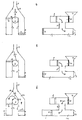
- the starting point is a slide housing (12) which has four openings.
- the two delivery cylinders (1 + 2) are connected at two entrances. Another opening is occupied by the suction line (5) with the boost pressure device (8) and the reservoir (9). On the opposite side opens the pressure line (7).
- the connections are made by a changeover device (6), for example by a rotary valve, which forms in the housing for each delivery cylinder alternately a pressure (14) and a suction channel (15).
- FIG. 1 the beginning of the pumping cycle is shown.
- the changeover device (6) connects the pump cylinder (2) to the delivery line (7) and the storage container (9) via the open slide (10) and the suction line (5) to the suction cylinder (1).
- the boost pressure device (8) is connected to the suction line (5) and also sucks Thick material from the reservoir. Since the suction side has a very low pressure level, the switching device (6) with the pressure difference between the suction side and pressure side is additionally pressed against the stops (13).
- the sucking piston (3) has reached the switching point (a). Up to this point, the boost pressure device has also sucked in its maximum volume. By closing the slide (10) of the reservoir (9) is separated from the suction line (5).
- the boost pressure device (8) begins to push and presses on the suction line (5) material in the cylinder (1) and compresses this simultaneously.
- the pressure piston (4) presses thick material into the delivery line (7) at the desired speed and pressure.
- the sucking piston (3) now reaches the switching point (b), which is close to the end of the suction stroke at the switching point (c).
- the switching point (b) the switching of the switching device (6) begins in a middle position.
- the boost pressure device (8) still presses into the sucking cylinder (1) but also partly into the delivery line (7), which is still separated from the pressure piston (4), u. U. with decreasing power supplied.
- the sucking piston (3) reaches the end of the suction path and the pushing piston (4) reaches the end of the pumping section.
- FIG. 6 is the situation like in FIG. 1 achieved, except that the switching device and the delivery cylinder are changed over. The cycle starts again here.
Landscapes
- Engineering & Computer Science (AREA)
- Mechanical Engineering (AREA)
- General Engineering & Computer Science (AREA)
- Reciprocating Pumps (AREA)
- Control Of Positive-Displacement Pumps (AREA)
- Structures Of Non-Positive Displacement Pumps (AREA)
- Power Steering Mechanism (AREA)
- Fuel-Injection Apparatus (AREA)
Claims (17)
- Pompe pour matières épaisses présentant au moins deux unités de pompage (1, 2) alternant en modes de pompage et d'aspiration, une conduite de refoulement (7), une conduite d'aspiration (5) avec un dispositif de pression d'admission (8) qui y est monté fonctionnant séparément des unités de pompage (1, 2) permettant de provoquer activement une compression des matières épaisses, un réservoir (9) relié à la conduite d'aspiration et un dispositif d'inversion de marche (6) pour la commutation entre les unités de pompage (1, 2), où par le dispositif d'inversion de marche (6), une unité de pompage (2 ; 1) est reliée en mode de pompage à la conduite de refoulement (7) et une unité de pompage (1 ; 2) en mode d'aspiration à la conduite d'aspiration (5), caractérisée en ce que le réservoir (9) peut être séparé de la conduite d'aspiration (5) avec le dispositif de pression d'admission (8) qui y est monté par une autre vanne (10) et dans la zone de la phase de commutation, le dispositif de pression d'admission (8) est relié entièrement ou en partie à la conduite de refoulement (7).
- Pompe pour matières épaisses selon la revendication 1, caractérisée en ce que la vanne (10) passe d'un état ouvert à un état fermé à un moment où un piston aspirant (3) de l'unité de pompage (1) se trouvant en mode aspiration atteint un poste de commutation (a) et le dispositif de pression d'admission (8) est rempli, de sorte que la conduite d'aspiration (5) avec le dispositif de pression d'admission (8) qui y est monté est séparé du réservoir (9).
- Pompe pour matières épaisses selon l'une quelconque des revendications 1 ou 2, caractérisée en ce que le dispositif de pression d'admission (8) débite lorsque la vanne (10) est fermée dans l'unité de pompage (1 ; 2) reliée à la conduite d'aspiration (5).
- Pompe pour matières épaisses selon l'une quelconque des revendications 1 à 3, caractérisée en ce que le dispositif de pression d'admission (8) débite au début de la phase de commutation dans l'unité de pompage (1 ; 2) reliée à la conduite d'aspiration (5) et dans la conduite de refoulement (7).
- Pompe pour matières épaisses selon l'une quelconque des revendications 1 à 4, caractérisée en ce qu'à la fin de la course d'aspiration du piston aspirant (3) de l'unité de pompage (1) se trouvant en mode aspiration et à la fin de la course de pompage du piston de compression (4) de l'unité de pompage (2) se trouvant en mode de pompage, l'alimentation de la conduite de refoulement (7) est prise en charge en ce qui concerne la quantité et la pression pour une courte période par le dispositif de pression d'admission (8).
- Pompe pour matières épaisses selon l'une quelconque des revendications 1 à 5, caractérisée en ce que la vanne (10) passe à la fin de la phase de commutation d'une position fermée à une position ouverte.
- Pompe pour matières épaisses selon l'une quelconque des revendications 1 à 6, caractérisée en ce que le débit de refoulement du dispositif de pression d'admission (8) compense entièrement ou en partie, l'interruption ou la diminution du débit de matières épaisses dans la conduite de refoulement (7) survenant pendant la phase de commutation.
- Pompe pour matières épaisses selon l'une quelconque des revendications 1 à 7, caractérisée en ce que la liaison s'effectue par le biais du dispositif d'inversion de marche (6).
- Pompe pour matières épaisses selon l'une quelconque des revendications 1 à 8, caractérisée en ce que le dispositif d'inversion de marche (6) est logé dans un carter (12) séparé du réservoir (9).
- Pompe pour matières épaisses selon l'une quelconque des revendications 1 à 9, caractérisée en ce que le carter (12) possède au moins quatre ouvertures auxquelles les cylindres de refoulement (1 + 2), la conduite de refoulement (7) et la conduite d'aspiration (5) avec le dispositif de pression d'admission (8) sont raccordés.
- Pompe pour matières épaisses selon l'une quelconque des revendications 1 à 10, caractérisée en ce que le dispositif d'inversion de marche est conçu comme bifurcation tubulaire (6a) et est monté dans un carter (12a).
- Pompe pour matières épaisses selon l'une quelconque des revendications 1 à 11, caractérisée en ce que la bifurcation tubulaire (6a) est reliée solidement à la conduite d'aspiration (5) et au dispositif de pression d'admission (8) et peut être raccordée brièvement à la conduite de refoulement (7).
- Pompe pour matières épaisses selon l'une quelconque des revendications 1 à 12, caractérisée en ce que les raccords de la bifurcation tubulaire (16 + 17) à la conduite d'aspiration (5) et au dispositif de pression d'admission (8) se font face et l'axe de rotation (19) passe par le milieu des raccords.
- Pompe pour matières épaisses selon l'une quelconque des revendications 1 à 13, caractérisée en ce qu'il y a un accès (18) à la conduite de refoulement (7) entre les ouvertures des cylindres de refoulement (1 + 2).
- Pompe pour matières épaisses selon l'une quelconque des revendications 1 à 14, caractérisée en ce que le dispositif de pression d'admission (8) est relié à la conduite de refoulement via la position médiane de la bifurcation tubulaire (6a) et l'accès (18).
- Pompe pour matières épaisses selon l'une quelconque des revendications 1 à 15, caractérisée en ce que le dispositif d'inversion de marche est conçu comme vanne rotative (6b).
- Pompe pour matières épaisses selon l'une quelconque des revendications 1 à 16, caractérisée en ce que la vanne rotative (6b) constitue tour à tour pour chaque cylindre un canal d'aspiration (14) et un canal de compression (15) et forme un double canal dans une position médiane (14/15) qui relie le dispositif de pression d'admission (8) à la conduite de refoulement (7).
Applications Claiming Priority (3)
| Application Number | Priority Date | Filing Date | Title |
|---|---|---|---|
| DE10240256 | 2002-08-31 | ||
| DE10240256A DE10240256A1 (de) | 2002-08-31 | 2002-08-31 | Dickstoffpumpe |
| PCT/EP2003/009418 WO2004025119A2 (fr) | 2002-08-31 | 2003-08-26 | Pompe pour matieres epaisses |
Publications (2)
| Publication Number | Publication Date |
|---|---|
| EP1599672A2 EP1599672A2 (fr) | 2005-11-30 |
| EP1599672B1 true EP1599672B1 (fr) | 2008-02-20 |
Family
ID=31502216
Family Applications (1)
| Application Number | Title | Priority Date | Filing Date |
|---|---|---|---|
| EP03775139A Expired - Lifetime EP1599672B1 (fr) | 2002-08-31 | 2003-08-26 | Pompe pour matieres epaisses |
Country Status (5)
| Country | Link |
|---|---|
| EP (1) | EP1599672B1 (fr) |
| AT (1) | ATE386882T1 (fr) |
| AU (1) | AU2003283233A1 (fr) |
| DE (2) | DE10240256A1 (fr) |
| WO (1) | WO2004025119A2 (fr) |
Families Citing this family (6)
| Publication number | Priority date | Publication date | Assignee | Title |
|---|---|---|---|---|
| DE102009005318B3 (de) * | 2009-01-16 | 2010-09-30 | Schwing, Friedrich, Dipl.-Ing. | Verfahren zur Förderung breiiger Massen und Pumpvorrichtung zur Förderung breiiger Massen |
| DE102012107933B4 (de) | 2012-08-28 | 2017-09-21 | Götz Hudelmaier | Dickstoffpumpe zur Erzeugung eines kontinuierlichen Dickstoffstroms sowie Verfahren zum Betrieb einer Dickstoffpumpe zur Erzeugung eines kontinuierlichen Dickstoffstroms |
| DE102012109332A1 (de) | 2012-10-01 | 2014-04-03 | Götz Hudelmaier | Verfahren und Vorrichtung zum Herstellen von im Boden eingelassenen Ortbetonstrukturen |
| DE102012109333A1 (de) | 2012-10-01 | 2014-04-03 | Götz Hudelmaier | Vorrichtung und Verfahren zum Ausbilden eines Hohlraums im Boden zum Herstellen einer im Boden eingelassenen Ortbetonstruktur |
| CN107355358A (zh) * | 2017-08-04 | 2017-11-17 | 中铁工程装备集团隧道设备制造有限公司 | 无间隙连续泵送的活塞式泵送装置及其控制方法 |
| CN110043438A (zh) * | 2019-05-24 | 2019-07-23 | 徐州徐工施维英机械有限公司 | 糊状物料输送装置和工程车辆 |
Family Cites Families (4)
| Publication number | Priority date | Publication date | Assignee | Title |
|---|---|---|---|---|
| GB1098338A (en) * | 1966-04-20 | 1968-01-10 | Eugene Lee Sherrod | Reciprocating pump for semi-liquid materials |
| US3663129A (en) * | 1970-09-18 | 1972-05-16 | Leon A Antosh | Concrete pump |
| DE2052583A1 (de) * | 1970-10-27 | 1972-05-04 | Bors, Heinz J., Campione (Schweiz) | Vorrichtung zum Fördern dickflüssiger Stoffe, insbesondere Beton, Mörtel und dgl |
| DE19957337A1 (de) * | 1999-11-29 | 2001-05-31 | Hudelmaier Joerg | Dickstoffpumpe |
-
2002
- 2002-08-31 DE DE10240256A patent/DE10240256A1/de not_active Withdrawn
-
2003
- 2003-08-26 WO PCT/EP2003/009418 patent/WO2004025119A2/fr not_active Ceased
- 2003-08-26 EP EP03775139A patent/EP1599672B1/fr not_active Expired - Lifetime
- 2003-08-26 DE DE50309228T patent/DE50309228D1/de not_active Expired - Lifetime
- 2003-08-26 AU AU2003283233A patent/AU2003283233A1/en not_active Abandoned
- 2003-08-26 AT AT03775139T patent/ATE386882T1/de not_active IP Right Cessation
Also Published As
| Publication number | Publication date |
|---|---|
| ATE386882T1 (de) | 2008-03-15 |
| AU2003283233A8 (en) | 2004-04-30 |
| EP1599672A2 (fr) | 2005-11-30 |
| AU2003283233A1 (en) | 2004-04-30 |
| WO2004025119A2 (fr) | 2004-03-25 |
| DE10240256A1 (de) | 2004-03-11 |
| DE50309228D1 (de) | 2008-04-03 |
| WO2004025119A3 (fr) | 2004-10-14 |
Similar Documents
| Publication | Publication Date | Title |
|---|---|---|
| EP0561262B1 (fr) | Pompe pour matière épaisse ayant des cylindres, en particulier pompe à béton à deux cylindres | |
| EP0861375B1 (fr) | Procede et dispositif pour commander une pompe a liquides epais a deux cylindres | |
| DE2462651C3 (de) | Betonpumpe | |
| EP1303700B1 (fr) | Pompe a liquides epais | |
| DE1950769C2 (de) | Freikolben-Brennkraftmaschine zum kurbelwellenlosen Antrieb einer Pumpe | |
| WO2002053914A1 (fr) | Pompe a membrane | |
| DE2444844A1 (de) | Verstaerker- oder druckerhoehungspumpe mit einem halbwellen-modulator | |
| DE1703829C3 (de) | Druckluftflüssigkeitsheber | |
| EP1599672B1 (fr) | Pompe pour matieres epaisses | |
| EP2324245A1 (fr) | Machine à piston hydrostatique équipée d'un dispositif de réduction de pulsations | |
| DE3029438C2 (de) | Anlage zum Entwässern von Schlamm mit mehreren parallelgeschalteten Filterpressen | |
| DE3042328A1 (de) | Kolbenpumpe | |
| WO1997005381A1 (fr) | Pompe | |
| DE102009008517B4 (de) | Hydraulischer Antrieb einer Dickstoffpumpe mit Ladedruckeinrichtung | |
| DE19542561C1 (de) | Hydraulische Ventilsteuerung | |
| WO2006125606A1 (fr) | Procede pour commander un dispositif de pompage pour le transport de masses pateuses et commande d'un dispositif de pompage pour le transport de masses pateuses | |
| DE1453500A1 (de) | Hydraulisch betaetigte Kolbenpumpe | |
| DE1653406C3 (de) | Hydraulisches Gestänge in einer zweizylindrischen Betonpumpe | |
| DE2022812C3 (de) | Antrieb einer hydraulischen Gesenkschmiedepresse für extrem kurze Spitzenbelastungszeiten | |
| WO2014166639A1 (fr) | Pompe à liquide épais à deux cylindres | |
| DE2065829A1 (de) | Hydraulisch angetriebene dreizylindrige schubkolbenpumpe | |
| DE102024108212A1 (de) | Pulsierende Förderpumpe zum Fördern von flüssigem oder pastösem Material | |
| DE2542392A1 (de) | Hochdruckmembranpumpe | |
| DE834530C (de) | Hydraulischer Arbeitskolben | |
| DE2329340C3 (de) | Pumpenanlage |
Legal Events
| Date | Code | Title | Description |
|---|---|---|---|
| PUAI | Public reference made under article 153(3) epc to a published international application that has entered the european phase |
Free format text: ORIGINAL CODE: 0009012 |
|
| 17P | Request for examination filed |
Effective date: 20050809 |
|
| AK | Designated contracting states |
Kind code of ref document: A2 Designated state(s): AT BE BG CH CY CZ DE DK EE ES FI FR GB GR HU IE IT LI LU MC NL PT RO SE SI SK TR |
|
| AX | Request for extension of the european patent |
Extension state: AL LT LV MK |
|
| DAX | Request for extension of the european patent (deleted) | ||
| GRAP | Despatch of communication of intention to grant a patent |
Free format text: ORIGINAL CODE: EPIDOSNIGR1 |
|
| GRAS | Grant fee paid |
Free format text: ORIGINAL CODE: EPIDOSNIGR3 |
|
| GRAA | (expected) grant |
Free format text: ORIGINAL CODE: 0009210 |
|
| AK | Designated contracting states |
Kind code of ref document: B1 Designated state(s): AT BE BG CH CY CZ DE DK EE ES FI FR GB GR HU IE IT LI LU MC NL PT RO SE SI SK TR |
|
| REG | Reference to a national code |
Ref country code: GB Ref legal event code: FG4D Free format text: NOT ENGLISH |
|
| REG | Reference to a national code |
Ref country code: CH Ref legal event code: EP |
|
| REG | Reference to a national code |
Ref country code: IE Ref legal event code: FG4D Free format text: LANGUAGE OF EP DOCUMENT: GERMAN |
|
| REF | Corresponds to: |
Ref document number: 50309228 Country of ref document: DE Date of ref document: 20080403 Kind code of ref document: P |
|
| PG25 | Lapsed in a contracting state [announced via postgrant information from national office to epo] |
Ref country code: FI Free format text: LAPSE BECAUSE OF FAILURE TO SUBMIT A TRANSLATION OF THE DESCRIPTION OR TO PAY THE FEE WITHIN THE PRESCRIBED TIME-LIMIT Effective date: 20080220 Ref country code: ES Free format text: LAPSE BECAUSE OF FAILURE TO SUBMIT A TRANSLATION OF THE DESCRIPTION OR TO PAY THE FEE WITHIN THE PRESCRIBED TIME-LIMIT Effective date: 20080531 |
|
| NLV1 | Nl: lapsed or annulled due to failure to fulfill the requirements of art. 29p and 29m of the patents act | ||
| PG25 | Lapsed in a contracting state [announced via postgrant information from national office to epo] |
Ref country code: SI Free format text: LAPSE BECAUSE OF FAILURE TO SUBMIT A TRANSLATION OF THE DESCRIPTION OR TO PAY THE FEE WITHIN THE PRESCRIBED TIME-LIMIT Effective date: 20080220 |
|
| REG | Reference to a national code |
Ref country code: IE Ref legal event code: FD4D |
|
| PG25 | Lapsed in a contracting state [announced via postgrant information from national office to epo] |
Ref country code: SK Free format text: LAPSE BECAUSE OF FAILURE TO SUBMIT A TRANSLATION OF THE DESCRIPTION OR TO PAY THE FEE WITHIN THE PRESCRIBED TIME-LIMIT Effective date: 20080220 Ref country code: DK Free format text: LAPSE BECAUSE OF FAILURE TO SUBMIT A TRANSLATION OF THE DESCRIPTION OR TO PAY THE FEE WITHIN THE PRESCRIBED TIME-LIMIT Effective date: 20080220 Ref country code: CZ Free format text: LAPSE BECAUSE OF FAILURE TO SUBMIT A TRANSLATION OF THE DESCRIPTION OR TO PAY THE FEE WITHIN THE PRESCRIBED TIME-LIMIT Effective date: 20080220 Ref country code: PT Free format text: LAPSE BECAUSE OF FAILURE TO SUBMIT A TRANSLATION OF THE DESCRIPTION OR TO PAY THE FEE WITHIN THE PRESCRIBED TIME-LIMIT Effective date: 20080721 Ref country code: NL Free format text: LAPSE BECAUSE OF FAILURE TO SUBMIT A TRANSLATION OF THE DESCRIPTION OR TO PAY THE FEE WITHIN THE PRESCRIBED TIME-LIMIT Effective date: 20080220 Ref country code: SE Free format text: LAPSE BECAUSE OF FAILURE TO SUBMIT A TRANSLATION OF THE DESCRIPTION OR TO PAY THE FEE WITHIN THE PRESCRIBED TIME-LIMIT Effective date: 20080520 Ref country code: IE Free format text: LAPSE BECAUSE OF FAILURE TO SUBMIT A TRANSLATION OF THE DESCRIPTION OR TO PAY THE FEE WITHIN THE PRESCRIBED TIME-LIMIT Effective date: 20080220 |
|
| ET | Fr: translation filed | ||
| PG25 | Lapsed in a contracting state [announced via postgrant information from national office to epo] |
Ref country code: RO Free format text: LAPSE BECAUSE OF FAILURE TO SUBMIT A TRANSLATION OF THE DESCRIPTION OR TO PAY THE FEE WITHIN THE PRESCRIBED TIME-LIMIT Effective date: 20080220 |
|
| PLBE | No opposition filed within time limit |
Free format text: ORIGINAL CODE: 0009261 |
|
| STAA | Information on the status of an ep patent application or granted ep patent |
Free format text: STATUS: NO OPPOSITION FILED WITHIN TIME LIMIT |
|
| 26N | No opposition filed |
Effective date: 20081121 |
|
| PG25 | Lapsed in a contracting state [announced via postgrant information from national office to epo] |
Ref country code: MC Free format text: LAPSE BECAUSE OF NON-PAYMENT OF DUE FEES Effective date: 20080831 |
|
| REG | Reference to a national code |
Ref country code: CH Ref legal event code: PL |
|
| GBPC | Gb: european patent ceased through non-payment of renewal fee |
Effective date: 20080826 |
|
| PG25 | Lapsed in a contracting state [announced via postgrant information from national office to epo] |
Ref country code: BG Free format text: LAPSE BECAUSE OF FAILURE TO SUBMIT A TRANSLATION OF THE DESCRIPTION OR TO PAY THE FEE WITHIN THE PRESCRIBED TIME-LIMIT Effective date: 20080520 Ref country code: EE Free format text: LAPSE BECAUSE OF FAILURE TO SUBMIT A TRANSLATION OF THE DESCRIPTION OR TO PAY THE FEE WITHIN THE PRESCRIBED TIME-LIMIT Effective date: 20080220 |
|
| PG25 | Lapsed in a contracting state [announced via postgrant information from national office to epo] |
Ref country code: CH Free format text: LAPSE BECAUSE OF NON-PAYMENT OF DUE FEES Effective date: 20080831 Ref country code: LI Free format text: LAPSE BECAUSE OF NON-PAYMENT OF DUE FEES Effective date: 20080831 |
|
| PG25 | Lapsed in a contracting state [announced via postgrant information from national office to epo] |
Ref country code: BE Free format text: LAPSE BECAUSE OF NON-PAYMENT OF DUE FEES Effective date: 20080831 Ref country code: CY Free format text: LAPSE BECAUSE OF FAILURE TO SUBMIT A TRANSLATION OF THE DESCRIPTION OR TO PAY THE FEE WITHIN THE PRESCRIBED TIME-LIMIT Effective date: 20080220 |
|
| PG25 | Lapsed in a contracting state [announced via postgrant information from national office to epo] |
Ref country code: AT Free format text: LAPSE BECAUSE OF NON-PAYMENT OF DUE FEES Effective date: 20080826 |
|
| PG25 | Lapsed in a contracting state [announced via postgrant information from national office to epo] |
Ref country code: GB Free format text: LAPSE BECAUSE OF NON-PAYMENT OF DUE FEES Effective date: 20080826 |
|
| PG25 | Lapsed in a contracting state [announced via postgrant information from national office to epo] |
Ref country code: LU Free format text: LAPSE BECAUSE OF NON-PAYMENT OF DUE FEES Effective date: 20080826 Ref country code: HU Free format text: LAPSE BECAUSE OF FAILURE TO SUBMIT A TRANSLATION OF THE DESCRIPTION OR TO PAY THE FEE WITHIN THE PRESCRIBED TIME-LIMIT Effective date: 20080821 |
|
| PG25 | Lapsed in a contracting state [announced via postgrant information from national office to epo] |
Ref country code: GR Free format text: LAPSE BECAUSE OF FAILURE TO SUBMIT A TRANSLATION OF THE DESCRIPTION OR TO PAY THE FEE WITHIN THE PRESCRIBED TIME-LIMIT Effective date: 20080521 |
|
| REG | Reference to a national code |
Ref country code: FR Ref legal event code: PLFP Year of fee payment: 14 |
|
| REG | Reference to a national code |
Ref country code: DE Ref legal event code: R082 Ref document number: 50309228 Country of ref document: DE Representative=s name: DF-MP DOERRIES FRANK-MOLNIA & POHLMAN PATENTAN, DE |
|
| REG | Reference to a national code |
Ref country code: FR Ref legal event code: PLFP Year of fee payment: 15 |
|
| PGFP | Annual fee paid to national office [announced via postgrant information from national office to epo] |
Ref country code: DE Payment date: 20180221 Year of fee payment: 15 |
|
| PGFP | Annual fee paid to national office [announced via postgrant information from national office to epo] |
Ref country code: IT Payment date: 20180221 Year of fee payment: 15 Ref country code: FR Payment date: 20180222 Year of fee payment: 15 Ref country code: TR Payment date: 20180213 Year of fee payment: 15 |
|
| REG | Reference to a national code |
Ref country code: DE Ref legal event code: R119 Ref document number: 50309228 Country of ref document: DE |
|
| PG25 | Lapsed in a contracting state [announced via postgrant information from national office to epo] |
Ref country code: DE Free format text: LAPSE BECAUSE OF NON-PAYMENT OF DUE FEES Effective date: 20190301 Ref country code: IT Free format text: LAPSE BECAUSE OF NON-PAYMENT OF DUE FEES Effective date: 20180826 |
|
| PG25 | Lapsed in a contracting state [announced via postgrant information from national office to epo] |
Ref country code: FR Free format text: LAPSE BECAUSE OF NON-PAYMENT OF DUE FEES Effective date: 20180831 |
|
| PG25 | Lapsed in a contracting state [announced via postgrant information from national office to epo] |
Ref country code: TR Free format text: LAPSE BECAUSE OF NON-PAYMENT OF DUE FEES Effective date: 20180826 |