EP1599343B1 - Systeme d'impression, ainsi que procede et produit programme informatique faisant intervenir un moyen pour surveiller l'integrite des donnees d'impression - Google Patents
Systeme d'impression, ainsi que procede et produit programme informatique faisant intervenir un moyen pour surveiller l'integrite des donnees d'impression Download PDFInfo
- Publication number
- EP1599343B1 EP1599343B1 EP04713534.8A EP04713534A EP1599343B1 EP 1599343 B1 EP1599343 B1 EP 1599343B1 EP 04713534 A EP04713534 A EP 04713534A EP 1599343 B1 EP1599343 B1 EP 1599343B1
- Authority
- EP
- European Patent Office
- Prior art keywords
- control
- numbers
- printed
- printing
- page
- Prior art date
- Legal status (The legal status is an assumption and is not a legal conclusion. Google has not performed a legal analysis and makes no representation as to the accuracy of the status listed.)
- Expired - Lifetime
Links
Images


Classifications
-
- B—PERFORMING OPERATIONS; TRANSPORTING
- B42—BOOKBINDING; ALBUMS; FILES; SPECIAL PRINTED MATTER
- B42C—BOOKBINDING
- B42C19/00—Multi-step processes for making books
-
- B—PERFORMING OPERATIONS; TRANSPORTING
- B41—PRINTING; LINING MACHINES; TYPEWRITERS; STAMPS
- B41J—TYPEWRITERS; SELECTIVE PRINTING MECHANISMS, i.e. MECHANISMS PRINTING OTHERWISE THAN FROM A FORME; CORRECTION OF TYPOGRAPHICAL ERRORS
- B41J29/00—Details of, or accessories for, typewriters or selective printing mechanisms not otherwise provided for
- B41J29/38—Drives, motors, controls or automatic cut-off devices for the entire printing mechanism
- B41J29/393—Devices for controlling or analysing the entire machine ; Controlling or analysing mechanical parameters involving printing of test patterns
-
- B—PERFORMING OPERATIONS; TRANSPORTING
- B41—PRINTING; LINING MACHINES; TYPEWRITERS; STAMPS
- B41J—TYPEWRITERS; SELECTIVE PRINTING MECHANISMS, i.e. MECHANISMS PRINTING OTHERWISE THAN FROM A FORME; CORRECTION OF TYPOGRAPHICAL ERRORS
- B41J3/00—Typewriters or selective printing or marking mechanisms characterised by the purpose for which they are constructed
- B41J3/60—Typewriters or selective printing or marking mechanisms characterised by the purpose for which they are constructed for printing on both faces of the printing material
-
- B—PERFORMING OPERATIONS; TRANSPORTING
- B65—CONVEYING; PACKING; STORING; HANDLING THIN OR FILAMENTARY MATERIAL
- B65H—HANDLING THIN OR FILAMENTARY MATERIAL, e.g. SHEETS, WEBS, CABLES
- B65H2301/00—Handling processes for sheets or webs
- B65H2301/50—Auxiliary process performed during handling process
- B65H2301/51—Modifying a characteristic of handled material
- B65H2301/511—Processing surface of handled material upon transport or guiding thereof, e.g. cleaning
- B65H2301/5111—Printing; Marking
-
- B—PERFORMING OPERATIONS; TRANSPORTING
- B65—CONVEYING; PACKING; STORING; HANDLING THIN OR FILAMENTARY MATERIAL
- B65H—HANDLING THIN OR FILAMENTARY MATERIAL, e.g. SHEETS, WEBS, CABLES
- B65H2511/00—Dimensions; Position; Numbers; Identification; Occurrences
- B65H2511/50—Occurence
- B65H2511/51—Presence
- B65H2511/512—Marks, e.g. invisible to the human eye; Patterns
Definitions
- the invention relates to a printing system, and more particularly to a method, a control device and a computer program product for monitoring printed data in a printing system. More particularly, the invention relates to a method of monitoring printed data in a high performance electrographic printing system.
- edge-punched, band-shaped paper as well as paper without edge perforation are used as the recording medium.
- the page numbers of the printed document can be used instead of the bar code. whereby it is possible to dispense with the printing of another control mark in the form of the bar code.
- a disadvantage of the previously known method is that the bar codes used in this case are very large and significantly affect the printed image of a printed page.
- a method for monitoring a high-performance production process for producing printed products is known.
- the sheets to be printed are conveyed in a predetermined direction.
- a picture of the sheet or a section of the printed sheet is detected by means of a camera.
- the process synchronizes individual sections of the manufacturing process and calibrates the position of the sheets in the manufacturing process.
- this method comprises a control device with which an alarm can be triggered if, for example, the sheets are not merged correctly.
- This control function evaluates the image taken by the chamber, in which case a predetermined portion of the printed image or a code, such as a bar code, is read and evaluated.
- the US 4,429,217 describes an apparatus and method for verifying credit cards, inserting credit cards into corresponding card cases, and stacking the card cases as appropriate for inserting the cards in envelopes.
- the cards are typically identified by specific information in the form of alphabetic, numeric or optical indicia (eg, 1-bar code or I-bar code) or information contained on magnetic stripes.
- the initial product may be provided with individual printed markers so that each bound end product has at least one such mark.
- the page number or a sequence of further pages can be added.
- the mark can also represent the end of a particular sequence, which can then be used to monitor whether all necessary sub-products are present.
- the mark is preferably printed in a region which is cut off at the end of the production process.
- the DE 10050 438 C1 discloses a method of synchronizing a plurality of paper-feeding channels of an inserter.
- Each sheet supplied by such a channel contains corresponding data or information identifying the membership of the sheet to a particular group, data identifying the sheet sequence within a group, and additional data indicating whether the sheet is a final or continuous one Sheet of a group.
- These data may be, for example, by means of a bar code, a 2 D code or other suitable coding on the sheets be upset.
- the group sequence number may consist of, for example, a six-digit number sequence and the sheet sequence number of a two-digit number sequence.
- the marking of an ongoing group or the group end can be in the form of a bit. In the case of an error, only one group is affected, which can be sorted out if necessary and supplemented by hand, for example.
- a tandem printing system is in the US-A-4,609,279 described.
- US-A-4,774,524 is for driving such a printing system provided to connect the main control devices of the two printers on the one hand via a host computer on a data control level and on the other hand via a second connection on a device control level.
- From the US B1-6,501,929 It is known to synchronize the printed page sequence in a tandem printing system via an electronic memory.
- a duplex printing system is known in which a control code is generated and printed for a page to be printed and the printed control code is evaluated.
- From the US-B1 6,246,856 is a printing device with two printing units for simultaneously printing the front and back of a web-shaped recording medium known. From the US-B1-.
- the above publications are hereby incorporated by reference into the present specification.
- a method for monitoring a high-performance production process for producing printed products is known.
- the sheets to be printed are conveyed in a predetermined direction.
- a picture of the sheet or a section of the printed sheet is detected by means of a camera.
- the process synchronizes individual sections of the manufacturing process and the position of the Bends calibrated in the manufacturing process.
- this method comprises a control device with which an alarm can be triggered if, for example, the sheets are not merged correctly.
- This control function evaluates the image taken by the camera, in which case a predetermined portion of the printed image or a code, such as a bar code, is read and evaluated.
- the US 5,265,008 relates to a system and a method for carrying out financial transactions by means of fax machines.
- a payment institution issues transaction vouchers to a particular customer, containing in the form of a bar code a series of alphanumeric random characters, each voucher printed with a different set of alphanumeric random characters.
- the party faxes this coupon to a central facility.
- the coupon will be read automatically and the set of alphanumeric characters will determine if this is an original coupon.
- Each coupon can only be used once.
- the individual vouchers of a customer must be used in a predetermined order.
- Each sheet of paper also prints a barcode that is a sequential number in the printing process.
- the barcode is automatically read after ordered workstations by means of a reader and compared with a serial number of the paper sheet. If the number of the barcode matches the serial number of the paper sheet, printing is OK.
- the invention has for its object to provide a method for monitoring printed data in a printing system which is suitable for using smaller codes compared to conventional bar codes, and with which, nevertheless, the page-by-page synchronization of a large print job can be safely monitored. Furthermore, the invention has for its object to provide a printing system for performing the method.
- control numbers are used as control codes which are not contained numerically in a checklist and that the checklist contains more control numbers than the number of counts contains control numbers. Individual control numbers are thus repeatedly included in the checklist. When evaluating the read control numbers, these can be compared in particular with the order of the control numbers of the checklist, with a deviation being assessed as an error.
- a very small number of sets can be used as the set of control numbers, such as a set of numbers consisting of a maximum of 64 numbers, and in particular a set of numbers consisting of a maximum of 16 Numbers, up to a number consisting of only eight, four or even two numbers, and yet it is possible to monitor a large number of pages.
- This is possible because, in contrast to conventional methods, in which each individual control number has a high information capacity, the information is transferred from the control numbers to the checklist in which this information is stored by the order of the individual control numbers. The larger the entropy in the numerical sense of the checklist, the greater the information contained in the checklist.
- a decimal range of, for example, 0 to 99 is printed as a binary number in the form of a bar or bar code as a control mark. These binary numbers comprise seven digits and therefore form a correspondingly long bar or bar code.
- control number is a one-digit binary number, that is, each control number is either "0" or "1".
- the number of counts of the control numbers can thus be limited even to two numbers.
- a number of numbers can be used which comprises not more than 32, in particular not more than 16, or not more than 8 numbers.
- the checklist may be provided either as a stored data list or by a method (algorithm) for generating a consecutive sequence of control numbers. These methods are realized with typically pseudo-random number generators.
- the period with which the control numbers repeat in the checklist is preferably greater than the typical print volume being executed on the printing system or greater than the maximum page number that may fail in a printing problem without being otherwise noted. If the typical print jobs only cover a few to a hundred pages, then a repetition period of 100 control numbers is sufficient. If the print jobs are considerably more extensive, it is expedient to provide correspondingly longer repetition periods. If, however, a few thousand pages are not printed in a large print job, this is also noticeable in other ways without the need for the monitoring system. Therefore, the repetition periods do not have to comprise more than a thousand or a few thousand control numbers. In the context of the invention, it is of course also possible to use longer repetition periods. In particular, if the checklists are generated by means of pseudo-random number generators, the repetition period can be significantly increased.
- This method is characterized in that are used as control codes control numbers that are included in a checklist not numerically ascending or descending sequentially, and in evaluating the read control numbers, the control numbers of each sheet are compared with each other, and in case of a deviation, this as a mistake is judged.
- a complete sequence of n read control numbers is determined and based on this sequence it is determined at which page number of the print job the error has occurred.
- the determination of the page number can be done by means of a decoding table in which all sequences of n-control numbers and the corresponding page numbers are stored.
- it is also possible to determine the page number such that the control numbers are sequentially generated with a certain control number until the complete sequence of read control numbers has been generated, the number of control numbers generated being a measure of the page number.
- page also includes the terms "print image” and "print page”.
- a sheet-shaped recording medium if a sheet-shaped recording medium is used, a sheet can also be understood to mean a web section if a continuous sheet is used or web-shaped recording carrier (fanfold, continous or web-shaped recording carrier) is used, which is first printed in the web-like state and cut in a post-printing processing operation to a single sheet. In the latter procedure, an assignment to the finally generated sheet can already take place during the printing, if the corresponding post-processing operations are clearly defined.
- the method and the device can be designed to monitor the exact page assignment of print data on the print material, the so-called data integrity. This is particularly important in printing devices or printing systems of importance, having a plurality of printing units and in which at least two printing units on the same recording medium and in particular print on a portion of the recording medium, which is associated with an output sheet. As part of the second printing process, the printed bit marks are detected, the reading result is compared with the originally assigned code, and thus the printing process is controlled.
- a web-shaped recording medium can be cut in a later processing step along the area boundaries to the sheet shape.
- a method of monitoring area data integrity in transmitting print data from a data source to a data receiver, wherein the print data is transmitted are sequentially numbered according to an N-digit binary number, where N is a natural number.
- the serial number is used to read a one-digit control code from a checklist and to read the print data of the Transfer area.
- N is a natural number.
- N is a specific sequence of N single-digit control codes is included only once.
- the associated single-digit control code is read in each case in regions and, based on a comparison of the read sequence of single-digit control codes with the code sequences available in the checklist, a decision about the data integrity is automatically made.
- the data integrity in the area-by-area transfer or printing of print data can be checked with a simple, minimal single-digit binary control code.
- the binary control code is not disturbing when transmitting the data because it has so little information content.
- it allows a minimal print image in the form of a simple stroke, which in particular also corresponds to the area boundary, e.g. Page boundary of a document can be printed.
- the printed bar code can still be used as a control mark for processes following the printing process, such as cutting, folding or punching of the recording medium.
- an N-digit read binary number associated with an area is formed and the consecutive numbering is reconstructed and checked therewith; this can be done by determining their position in the checklist and comparing the number associated with that position with the sequential number of the area generated during transmission.
- the N-digit read binary number is assigned to an area whose read control code is contained in the N-digit read binary number and in particular the area whose read.
- the N-digit read binary number is assigned to an area whose read control code is contained in the N-digit read binary number and, in particular, the area whose read control code is at the first or last digit of the N-digit read binary number. On the basis of the comparison result can then be decided automatically whether in the data transmission partially data has been lost.
- the result of the comparison can be used to automatically determine the number of areas where data has been lost.
- a computer or a controller, especially a printer may be used as the data source.
- a data receiver a controller, a printing unit, each of which prints the single-digit binary control code as a bit mark on a region of the recording medium and / or in particular a recording medium as a carrier of the printed information including the control code.
- the printed bit marks can be read with a sensor and the reading result compared with the control code associated with the transmission and thus the printing process can be controlled.
- associated print data of a region eg in form fields of forms or on the front and back of the document
- one or more printing units on the document be verifiable in terms of their data integrity or correct togetherness
- the checklist may also be provided according to the fourth aspect as a stored data list or by means of a method (algorithm) for generating a successive sequence of control numbers, i. both the sending system (data source) and the receiving system (data receiver) may optionally be connected to the checklist as a stored list, e.g. Look-up-table (LUT) or calculate the control numbers of the checklist online with a computer processor.
- algorithm for generating a successive sequence of control numbers, i. both the sending system (data source) and the receiving system (data receiver) may optionally be connected to the checklist as a stored list, e.g. Look-up-table (LUT) or calculate the control numbers of the checklist online with a computer processor.
- the invention also provides devices, printing devices, controllers or computer software that can automatically effect a sequence according to the invention.
- FIG. 1 A printing system for carrying out the method according to the invention is schematically simplified in FIG FIG. 1 shown.
- This printing system has a printer 1, which is preferably a high-performance printer, for printing on a paper web 2.
- the printer 1 is connected via a data line 3 to a computer 4, from which the printer 1 via the data line 3, a print data stream receives.
- the computer 4 is either a server that merely caches or forwards the print data stream or a host to which the print job and the corresponding print data stream are generated.
- the print data stream used is the IPDS (Intelligent Printer Data Stream) print data stream typical for high-performance printers.
- IPDS Intelligent Printer Data Stream
- print data streams in other formats, such as PCL (Print Command Language), PS (Post Script) or AFP (Advanced Function Presentation).
- the data line 3 leads to a controller 5, in which the print data contained in the print data stream are processed for a subsequently arranged character generator.
- the character generator 6 generates control signals for driving a printing unit 19 with a photoconductor drum 7, with which the printing data are printed on the paper web 2.
- the character generator 6 and the photoconductive drum 7 constitute a printing unit 19.
- the controller 5 is further connected to a device controller, not shown, which drives the various units of the printing apparatus, e.g. The paper transport, the electrophotography unit, the fuser, etc.
- the controller 5 is connected to a control panel 20, displayed on the system information and can be made via the settings on the printer 1. It may include known means such as a screen (esp. Touch-screen), keyboard and / or mouse, etc.
- the paper web 2 is typically a continuous paper web for high-performance printers. However, there are now also known printers with very high performance, which print on single sheets, in which the application of the method according to the invention is also expedient.
- control numbers are generated and inserted into the print data stream. This will be explained below.
- a sensor 8 for scanning the printed on the paper web 2 control numbers is provided adjacent to the paper web 2. If the control numbers are printed in the form of a bar or bar code, the sensor is a simple photo sensor which detects the brightness differences on the paper web.
- the sensor 8 is connected to a monitoring device 9, which in turn is coupled to a central pressure controller 10.
- the paper web 2 is driven by a conveyor 13 in the conveying direction 14.
- the data stream delivered via data line 3 contains additional information about the print job, such as a print job. Sheet or page numbers that are supplied via a further data line 11 to a monitoring device 9. Alternatively, this additional information can initially only be supplied to the controller 5, which then forwards it to the monitoring device 9 via a further data line 12. The data line 11 can then be omitted. It is also possible in this case that the controller 5 generates the additional information about the print job itself and delivers it to the monitoring device 9 if the computer 4 does not provide such information.
- the control signal (A) is a central start / stop signal with which the beginning and the end of a printing process are marked.
- the control signal is usually generated by the character generator 6 as soon as it receives the information from the controller 5 that sufficient print data prepared for the printing process are available.
- the control signal (B) is a clock signal which predetermines a predetermined clock, which synchronizes all of the am Enabling the printing process and is constantly available.
- the individual devices of the printer 1 can determine on the basis of the start / stop signal (A) and the clock signal (B) when the individual pages or predetermined locations on the pages pass them. Usually there is a delay (C1) at the beginning of a printing process until the leading edge of the first page passes a predetermined location in the printer 1 and the cycle time (C2) of the further pages is usually constant.
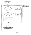
- step S2 the controller 5 reads the printing data coming from the computer 4 via the data line 3.
- a means for generating control numbers is provided, with which the control numbers are provided (step S3).
- This facility can be a list of stored control numbers.
- this device can also be designed as a method. Such methods are, for example, pseudo-random number generators.
- the controller 5 and the monitoring device 9 must synchronize their devices with each other, so that both devices in each case the same Provide a sequence of control numbers.
- Such a synchronization can take place by means of a synchronization command from the controller 5 via the data line 12 to the monitoring device 9.
- This synchronization takes place, for example, after an interruption of the printing process due to an error condition and after the error condition has been remedied.
- An error condition in this sense is also a detected by the monitoring unit 9 error in the printing process.
- the sequence of control numbers should have as low a redundancy as possible, that is to say that sequences with a certain number of control numbers preferably occur only once in the entire list of control numbers. In other words, this means that the entropy should be as large as possible in the numerical order of the control number sequence.
- the sequence of numbers 1, 0, 1, 0, 1, 0 ... has a very high degree of redundancy and a very low entropy, since this sequence repeats with the period two. It is expedient to provide significantly longer repetition periods. For printing systems intended for small print jobs, a repetition period of 100 may already be sufficient. More advantageously, however, larger repetition periods of at least 1000, 10000 or more are to be used.
- control numbers thus generated are inserted in the print data (step S4).
- a character is inserted in each page to be printed at a predetermined location in the print data, which reproduces the control number.
- Such a sign is also called a control mark.
- control numbers a small number of numbers with, for example, sixteen, eight, four or only two numbers corresponding to a few places, for example as a single-digit or two-digit Control numbers are displayed.
- Such control numbers can be printed with a smaller area brand than control numbers from a larger number of numbers.
- control numbers in any number system, such as a hexadecimal, decimal or binary number system.
- control numbers in the binary system.
- the control numbers are preferably represented by bar or bar code, as these are easily detected automatically. In this case, either a thin or thick bar or an existing or a nonexistent bar is provided for each digit of the binary number.
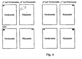
- FIG. 4 shown here in each case the front and back of a sheet is shown, on which the corresponding control numbers are printed in the form of a bar code.
- the bar code is binary in this example, ie only one zero or one is coded. The zero can by no stroke (in the upper sides of the FIG. 4 shown) or by a relatively thin line (in the lower sides of the FIG.
- the one is then coded by a stroke (upper sides) or by a relatively thick stroke (lower sides).
- An advantage of using the variant with different line widths is that on each page to be printed in a given range, a single line can be printed, the downstream of the printing devices such as cutting sensory detected and as a trigger mark for certain actions such as cutting the Record carrier can be used on side transitions.
- the line can be printed in particular along the page boundary at the side transitions of a web-shaped recording medium, whereby it virtually completely disappears after a cutting operation and therefore can no longer be annoying.
- the barcode may also comprise a plurality of dashes and / or for the invention Control numbers of more than one bit represent information content.
- step S5 After inserting the control numbers in the print data they are printed by the printing unit on the paper web 2 (step S5). This completes the process of generating and printing the control numbers (step S6).
- step S7 the control marks or control numbers printed on the paper web 2 are scanned by means of the sensor 8.
- the sampling process is timed by the start / stop signal (A) and the clock signal (B) ( FIG. 2 ) controlled. As a result, exactly predetermined areas can be scanned on the respective printed pages.
- the sensor 8 converts the sampled light signals into digital signals, namely into the control numbers and forwards them to the monitoring device 9.
- the read control number is compared with a corresponding check number of the checklist (step S9).
- the checklist can in turn be stored in the form of a prestored data list in the monitoring device 9 or be generated by means of a predetermined method, such as a pseudo-random number generator. Regardless of how the sequence of control numbers is provided in the monitoring device 9, this sequence of control numbers must be synchronized with the sides to be monitored. This is done in the present embodiment in that the first Assigned control number in the checklist of the first by the start / stop signal (A) and the clock signal (B) side defined and the other control numbers of the list in the order in the checklist assigned to the pages following to the first page in this order with which they are also inserted by the controller 5 in the pages of the print data.
- A start / stop signal
- B clock signal
- step S9 If it is determined in this comparison (step S9) that the read control number should not be the same as the corresponding check number of the checklist, this means that the sensor has scanned a check number which does not correspond to the page which is located at the corresponding position in the Sequence of pages of the printing process should be present. Such a deviation is thus assessed as an error. A corresponding error message is passed on to the print controller 10 (step S10).
- step S11 in which it is checked whether another control number is to be sampled. If this is the case, the process flow returns to step S8, otherwise the process is terminated with step S12.
- step S9 If the comparison in step S9 shows that the read control number is equal to the corresponding check number in the checklist, the method proceeds directly from step S9 to step S11.
- This method can be modified such that not only is it determined whether the correct control number is read by the sensor 8, but it is also determined whether the control number passes exactly at the predetermined time at which it is to pass the sensor, and if there is a time difference, it can be measured, for example in units of the clock signal. By determining this time deviation, the deviation becomes the control number measured from the ideal position on the paper web. As a result, the registration accuracy of the imprint on the paper web can also be determined.
- the information contained in the order of the check numbers present in the checklist is used, the information contained in a check number can be very small. It is therefore even possible to use only a single-digit binary number as a control number. With the invention, the information contained in the control numbers is thus correlated with the information contained in the order of the control number.
- the coefficient k is used for inversion (variation) of the code values.
- the operator " ⁇ " denotes the bitwise exclusive-or-shortcut used to invert the calculated codes. It may be useful, for example, to use a sequence of control numbers for the front side and the corresponding sequence of inverted control numbers for the back side in the case of double-sided printing.
- the method according to the invention can be used very advantageously in a tandem printing system.
- a tandem printing system comprises two printers 1a, 1b (FIG. Fig. 3 ) each having a controller 5a, 5b, a row generator 6a, 6b, printing units, each one a photoconductor drum 7a regarding. 7b, a monitoring device 9a, 9b and a pressure control 10a, 10b.
- the two printers 1a, 1b print on a common paper web 2, wherein the paper web 2 is turned in the area between the two printers 1a, 1b by means of a turning device 15. It is thus printed by each printer 1a, 1b each have a side surface of the paper web, so that the paper web is printed on both side surfaces.
- the two printers 1a and 1b receive the print data stream via a respective data line 3a and 3b from a computer 4.
- the data stream contains additional information about the print job, e.g. Sheet or page numbers, which are also supplied to the monitoring devices 9a and 9b via further data lines 11a and 11b.
- this additional information can initially be supplied only to the controllers 5a and 5b, which then pass them on to the monitoring devices 9a or 9b via further data lines 12a or 12b.
- the data lines 11a and 11b can then be omitted. It is also possible in this case that the controllers 5a and 5b generate the additional information about the print job itself and deliver it to the monitoring devices 9a or 9b if the computer 4 does not provide such information.
- control signal (A) is a central start / stop signal with which the beginning and the end of a printing process are marked.
- the control signal is usually generated by the character generator 6a or 6b as soon as it receives the information from the controller 5a or 5b that the printing process can begin. This is the case in the printer 1a if sufficient print data prepared for the printing process are available in both printers 1a and 1b. In the printer 1b, this is the case when there there are enough print data available and additionally a sufficiently long paper web (supplied by printer 1a) is available for printing.
- the control signal (B) is a clock signal which predetermines a predetermined clock, which enables a temporal synchronization of all devices involved in the printing process and this is constantly available.
- the two printers 1a, 1b each individually and in particular also jointly as a so-called. Single point of operation operated.
- the printer 1a is arranged in the conveying direction (arrow 14) in front of the turning device 15 and similar to the printer 1 from FIG. 1 formed with a sensor 8a.
- the second printer 1b which is arranged in the conveying direction after the turning device 15, has two sensors 8b, 8c, wherein the sensor 8a adjacent to one side of the paper web 2 and the sensor 8c at the same height adjacent to the other side of the paper web 2 is arranged so that both sides of the paper web are scanned by the sensors 8b, 8c.
- the monitoring of the printing process is exactly as in the above-explained in FIG. 1 illustrated printing system.
- both sides of the paper web are monitored.
- control numbers are printed, which have been created for example by means of the same control list, where on one side, the control numbers are not inverted and on the other hand, the control numbers are inverted.
- two control numbers are read out for each paper sheet, one for the front and one for the back.
- the inverted control number is inverted again, so that the two read control numbers can be compared with each other and with the corresponding control number of the control list. If one of these three control numbers deviates one, there is an error and is output accordingly.
- the check list can in turn be provided by a predetermined list of control numbers, which is stored in the two controllers 5a, 5b. However, it can also be generated, for example, in the controller 5a by means of a suitable method and the control numbers can be forwarded via the data line 3 to the controller 5b of the printer 1b. Preferably, however, in the two controllers 5a, 5b, the control numbers are generated by a suitable method, such as a pseudo-random number generator. For this purpose, the random number generator is started with the same start parameters at a corresponding point in time.
- control numbers are passed on and processed by the page-by-side processing of the print data stream.
- control numbers are advanced by the page-by-page scanning of the control codes, which is enabled by the control signals (A) and (B) in synchronism with the printing operation.
- the printed control numbers printed in the form of a bar code can furthermore be used to control other processes which are carried out on the web-shaped recording medium or on the paper web, for example cutting, folding, punching, stapling or adhesive processes.
- a cutting device 16 is arranged, which has two sensors 17 a, 17 b on both sides of the paper web 2 to scan both turned and double-sided record carrier as well as unswept, printed on one side record carrier.
- One of the sensors 17a, 17b detects the printed bar code corresponding to the control code on the paper web 2.
- the scanning signal then controls the time at which the knife 18 of the cutting device cuts the paper web 2 into two parts.
- the blade 18 can be controlled so that it separates the paper web 2 exactly along the stroke. This makes it possible to achieve that the printed line is at the outermost edge of the cut paper or that the line is cut out or punched out and virtually no longer disturbs the paper sheet produced in the process.
- the above embodiment shows how the printing process in two printers of a tandem printing system can be synchronized with one another by means of the method according to the invention.
- a printing process with a post-processing process.
- Such post-processing processes are, for example, the cutting of paper webs, the punching or binding of the printed sheets.
- finishing devices There are a variety of different finishing devices known.
- a monitoring device with a corresponding sensor as used in the above-explained printers, is to be provided in the post-processing device.
- the checklist is provided in the monitoring device and read the control numbers of the sides to be monitored in order to be compared with the corresponding control numbers of the checklist.
- control numbers according to the invention can also be generated with the linear feedback shift register method, which is also referred to as LFSR method ("Linear Feedback Shift Register").
- LFSR method Linear Feedback Shift Register
- bit string can be generated which has the special property that any sequence of n consecutive bits within the entire sequence of N bits always occurs only once.
- the total length N of the bit sequence can be a maximum of 2 n .
- the number sequence is extended by one state: ... ⁇ 2 (n-1) ⁇ 0 ⁇ 1 ⁇ ...
- a sequence of n consecutive bits is understood as a coded page number.
- the coded page number can then be converted into the normal, uncoded page number.
- control numbers of eight consecutive pages give a complete page number.
- Each control number consists of two bits.
- the page numbers run from 1 to 65535.
- the bit sequence of N 65535 bits is traversed twice. In the second pass, the bit positions are offset by one from the first pass, thereby making the second pass distinguishable from the first pass.
- control numbers of five consecutive pages give a complete page number.
- Each control number consists of three bits.
- the page numbers run from 1 to 32768.
- the bit sequence of N 32768 bits is traversed three times.
- t-steps of the LFSR process are executed for each printed page (or printed sheet).
- t bits are supplied for each control number.
- This control number is printed on the paper according to the methods described above and detected by means of a monitoring device.
- the page number of a page is determined by reading the control number from this page as well as the control numbers of the previous pages m-1. The total of m control numbers are then assembled into a coded page number (according to a predetermined order).
- control numbers of the non-existent pages are replaced by defined replacement or initial values that correspond to the end sequence of the bit sequence generated by the LFSR method.
- initial value a the missing control numbers can always be set to 0.
- the method can also be realized in such a way that the control numbers of the "searched" page and the following m-1 pages are assembled. However, then the determination of the page number for the last m-1 pages of a print job is problematic or not possible.
- each page is printed with a control number consisting of one bit each.
- the first read control number is considered the most significant, the last one read as the least significant number.
- the missing control numbers on pages 1 to 15 are assumed to be "0".
- the end sequence of the sequence indicates that these control numbers actually take the value 0.
- a decoding method which supplies the uncoded page number z from the coded page number c.
- a decoding method which supplies the uncoded page number z from the coded page number c.
- the variant with the largest computation time and the smallest memory requirement uses the LFSR method, which is applied "backwards", ie opposite to the (encoding) LFSR method, which generated the control numbers.
- the number of passes d required is then counted until the LFSR method reaches the initial state of the first coded page number C 1 .
- the number of passes d can also be 0.
- the first table is a listing of intermediate values evenly distributed over all coded page numbers.
- the second table contains the information as to whether a particular coded page number c is contained in the first table.
- the second table comprises N bits, that is one bit per possible value c.
- the first table then contains 1024 values or 2048 bytes.
- the second table claims 65536 bits or 8 kbytes. The number of passes d is always in the range of 0 to 63, and within the first table a maximum of 1024 search steps are necessary.
- the LFSR bit sequence (1 to N) is traversed several times during a run of the page numbers (1 to Z).
- the page numbers are virtually "blended" into each other.
- the number of pages at which an error has occurred can thus be determined from the sequence of read control numbers.
- the LFSR method thus represents a preferred pseudo-random number generator, since the resulting sequence of control numbers is suitable for the subsequent determination of the page numbers.
- pseudo-random number generators instead of a pseudo-random number generator, other random number generators can be used.
- random number generators are known that use the thermal noise of a diode to generate the random numbers.
- Corresponding hardware components are commercially available. However, if no pseudo-random number generators but "true random number” generators are used, the relevant sequences of the random numbers must be recorded in the printing system and the monitoring devices made available.
- control numbers of at least n previous pages are stored in order to be able to indicate the earliest possible faulty page number in the event of an error. If the control numbers of the previous pages are not saved, to avoid erroneous printouts, all n previous pages must always be discarded and reprinted in the event of an error.
- the sequence B is the sequence of control numbers read from the printed pages.
- control numbers of the previous page 30 and the current page 31 are the same, i. H. it will be further investigated according to case b).
- the method according to the invention can be modified such that a single read error is tolerated if thereafter the check numbers of at least following pages match again, where i is equal to or greater than 10.
- the memory for the control numbers of the past pages must then include at least 2i numbers to indicate the range of a possible error.
- a page number can be decoded from this. This can be compared with a page number which is obtained, for example, by counting the printed sheets or is obtained by assigning to each check number of the checklist a page number which can then be correspondingly read out. From this comparison can be z. For example, you can see if and how many pages are missing in the printout or are duplicated. This is important for identifying and remedying possible causes of errors.
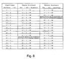
- Example 2 This example continues Example 2 above.
- This list shows the decoded page numbers after an error.
- the page numbers in column A result from the reference sequence
- the page numbers in column B result from the read control numbers. It turns out that the page numbers of column B over 15 pages are irregular and quasi disturbed, since in the expression one page and thus one bit of the associated page numbers was missing. From the reference page number 46, the page numbers of column B are again regular, and the difference between column B and column A indicates that exactly one page was missing. The assumption mentioned in Example 2 that pages could have been printed several times can thus be excluded. On page 31, where the error is first detected, this information is not yet apparent.
- FIGS. 1 and 3 illustrated printing systems used for logical control and monitoring of the printing process.
- Corresponding data integrity monitoring can also take place in other printing systems, for example in a printing system which has two printing units in a common housing for simultaneously printing the front side and the back side of a web-shaped or sheet-like recording medium, as is known from US Pat US B1-6,246,856 is known.
- bit marks are printed as so-called bit marks on each printed page.
- the bit marks each contain one bit of information, represented e.g. B. by a thin or thick line. Whether a "0" or a "1" is printed as a bit mark is determined by the controller on the basis of the LFSR algorithm already explained above, which is run through for each printed page.
- the LFSR algorithm is based on an N-bit key and generates a unique bit sequence of length 2 N bits. In each case N consecutive bits within the bit sequence are again unique and can therefore be understood as an "encrypted page number".
- N 12
- N 12
- the repetition rate for the page-by-page assignment of the control numbers (page numbers) in this case is 4096 pages.
- each N-digit binary control number exists only once, so there is a one-to-one correspondence between all start and end positions of N-digit sections with their respective position numbers (page numbers) .
- the same LFSR algorithm is used as in the controller.
- a first monitoring step the device controller checks to see if the state values supplied by the controller match the values calculated using its own LFSR algorithm.
- the printed bit marks are scanned with brand sensors.
- the device control evaluates the signals of the brand sensors and decodes the Scanning signals back to individual bits.
- the read bits must match the bits supplied by the LFSR algorithm. Even possible reading errors of the brand sensors can or must be taken into account. It may happen that a bit mark is either not read or misinterpreted. It is advantageous that individual read errors are tolerated within certain limits (eg N pages). A deviation of two or more bits within N pages causes the printing process to be aborted with an error message.
- the "encrypted" page number can be formed from N consecutively read bits and, in turn, a "real", consecutive page number can be decoded therefrom, as described above.
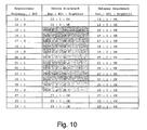
- FIGS. 8 to 11 illustrate a representation in which the generated control codes, the read control codes and any system messages that are generated based on the reading result and / or the comparison of the sequence of control codes and the read control codes are displayed.
- a display in tabular form is provided, which can be called up by the user (operator) at any time, and which is constantly updated during a running printing process.
- the first column in the table shows the sequence of the LFSR algorithm with the expected page number and the expected bit mark.
- Threshold values can be set for the evaluation, namely, how many errors of the first or second type may occur before the decision "data integrity error" is automatically made and the printing process is aborted.
- the error of the first kind may occur at most twice per 12 pages before the printing process is aborted, while the second type error may only occur a maximum of once per 12 pages before the printing process is aborted. If a first type error and a second type error occur within 12 pages, printing will continue.
- bit marks of page No. 14 on the lower printing unit and page No. 22 of the upper printing unit are not recognized.
- the missing bit mark can then be replaced by the expected bit mark of the algorithm, so that the page numbers continue to be properly decoded and displayed. The individual read errors are tolerated.
- the unrecognized mark ("mark missing") is marked in the color representation on the control panel with a first color, eg with yellow.
- FIG. 11 The example shown shows the procedure for two or more incorrectly read bit marks.
- the data source bitstream is (first column), starting at page 21 and ending at page 32: 111110111011.
- the lower print engine (right column) has all Data printed correctly and therefore between pages 21 and 32 the same bit string of printed bit marks.
- the bit marks printed correctly by the upper print engine end at page 19.
- a serious bit error occurs: A 1 is read, although a zero would be expected. If you then follow the read bit values until the page number 32 is decoded, it turns out that the above-mentioned bit pattern 111110111011 for the page number 32 already occurs at a position at which the first bit from the (computational) page number 20 (the first error occurred). From this it can be clearly concluded that a page has been lost in the printed page sequence. In the displayed list according to FIG. 11 this is immediately apparent to the viewer, because in the middle column for the upper printing unit, the page numbers from page 31 are shifted upwards by one line compared to the corresponding page numbers of the left column of the data source.
- the invention is described above with reference to examples which print a web-shaped recording medium, in particular a paper web, on one or both sides. However, it can also be used to synchronize differently colored printouts or to check the data integrity of printouts on cut sheets, especially when different data from different print engines are printed on a single cut sheet.
- Data integrity on a record carrier can be accomplished by comparing the control codes between the data source and the data receiver (such as in particular FIG. 8 described) or by comparison between the control codes of two data receivers, in particular, if the two data receivers are printing units or different areas (front / back) of a recording medium, which were printed with different printing units or in separate printing processes.
- control codes of the print data of both areas must be included the same number sequence or a number sequence transformation have been performed.
- Each sheet can print several print images on the front and back and / or in different colors. For full-color printing, for example, up to five (or more) individual color images are printed per sheet page.
- control number can be generated and printed in the form of a control mark.
- the control marks of different print images should not overlap.
- the control numbers of the individual print images do not have to be the same, but can be varied according to a fixed scheme; for example, the control numbers of the back side can be inverted to those of the front side.
- the read control numbers are compared with a reference sequence of control numbers supplied by an electronic circuit, a stored table, a calculation method or a random number generator.
- a missing or multiple printed sheet is recognized.
- control numbers are printed as control code, which are contained in a checklist.
- the control numbers are not sorted numerically in succession, but arranged in an arbitrary order with the highest possible entropy.
- the expression checks whether the control numbers have been printed in the same order as in the checklist. This makes it possible to use control numbers with few digits, in particular even single-digit binary numbers.
- control numbers can either be provided by stored checklists or the checklists can be generated by a corresponding method.
- a preferred method is the LFSR method, since control numbers are generated which are suitable for calculating the page numbers from the control numbers.
Landscapes
- Accessory Devices And Overall Control Thereof (AREA)
Claims (46)
- Procédé de surveillance de données imprimées dans un système d'impression contenant un appareil d'impression (1, 1a), comprenant les étapes suivantes :- génération d'un code de contrôle à chaque fois pour une page à imprimer,- impression du code de contrôle sur la page respective correspondante d'un support d'enregistrement à imprimer,- lecture automatique et interprétation du code de contrôle imprimé,des numéros de contrôle étant utilisés comme code de contrôle, lesquels sont contenus dans une suite non numérique dans une liste de contrôle, la liste de contrôle contenant plus de numéros de contrôle que les numéros de contrôle que contient la quantité de numéros utilisée.
- Procédé selon la revendication 1, caractérisé en ce que lors de l'interprétation des numéros de contrôle lus, ceux-ci sont comparés avec la séquence des numéros de contrôle de la liste de contrôle, un écart étant considéré comme une erreur.
- Procédé selon la revendication 1 ou 2, caractérisé en ce qu'au moins deux images imprimées possédant respectivement un code de contrôle sont imprimées sur une feuille à imprimer et, lors de l'interprétation des numéros de contrôle lus, les numéros de contrôle d'une feuille sont comparés entre eux et, en cas d'écart, ceci est considéré comme une erreur.
- Procédé selon la revendication 3, caractérisé en ce que tous les numéros de contrôle d'une feuille sont identiques.
- Procédé selon la revendication 3, caractérisé en ce que les numéros de contrôle des versos des feuilles sont inversés par rapport aux numéros de contrôle des rectos et les numéros de contrôle des versos sont inversés avant la comparaison avec les numéros de contrôle des rectos.
- Procédé selon l'une des revendications 1 à 5, caractérisé en ce que plusieurs images imprimées sont imprimées sur une page d'une feuille et un numéro de contrôle est associé à chaque image imprimée et celui-ci est imprimé sur la feuille.
- Procédé selon l'une des revendications 1 à 6, caractérisé en ce que les numéros de la liste de contrôle sont des numéros comprenant un maximum de trois chiffres et de préférence des numéros à un chiffre.
- Procédé selon l'une des revendications 1 à 7, caractérisé en ce que les numéros de contrôle sont des nombres binaires.
- Procédé selon l'une des revendications 1 à 8, caractérisé en ce que la liste de contrôle est mise à disposition sous la forme d'une liste mise en mémoire.
- Procédé selon l'une des revendications 1 à 8, caractérisé en ce que la liste de contrôle est mise à disposition au moyen d'un procédé de calcul prédéfini.
- Procédé selon la revendication 10, caractérisé en ce que le procédé de calcul destiné au calcul des numéros de la liste de contrôle est un générateur de numéros pseudo-aléatoires.
- Procédé selon la revendication 11, caractérisé en ce que le générateur de numéros pseudo-aléatoires utilisé est un procédé LFSR.
- Procédé selon l'une des revendications 1 à 12, caractérisé en ce que les numéros de la liste de contrôle possèdent une période de répétition minimale de 100, de préférence de 1000.
- Procédé selon l'une des revendications 1 à 13, caractérisé en ce que la liste comprend N numéros, une séquence quelconque de n numéros étant toujours présente une seule fois dans la liste.
- Procédé selon la revendication 14, caractérisé en ce qu'après qu'une erreur a été constatée, la dernière séquence complète de n numéros de contrôle lus est déterminée et le numéro de page qui suit l'erreur est déterminé à l'aide de cette séquence.
- Procédé selon la revendication 15, caractérisé en ce que la détermination du numéro de page s'effectue au moyen d'un tableau de décodage dans lequel sont mis en mémoire toutes les séquences de n numéros de contrôle et les numéros de page correspondants.
- Procédé selon la revendication 15, caractérisé en ce que pour déterminer le numéro de page, les numéros de contrôle sont générés au moyen d'un procédé prédéfini, en commençant par un numéro de contrôle donné jusqu'à ce que la séquence complète de n numéros de contrôle lus ait été générée, le nombre de numéros de contrôle générés étant une indication du numéro de page.
- Procédé selon l'une des revendications 14 à 17, caractérisé en ce qu'après avoir constaté une erreur et déterminé le numéro de page correspondant, une analyse est effectuée en comparant le numéro de page déterminé avec un numéro de page qui est présent du fait du comptage des feuilles imprimées ou par une association aux numéros de contrôle pour vérifier si- une ou plusieurs pages ont été imprimées plusieurs fois, et/ou- une ou plusieurs pages n'ont pas été imprimées.
- Procédé selon l'une des revendications 1 à 18, caractérisé en ce que les numéros de contrôle sont imprimés sous la forme d'un code à barres.
- Procédé selon la revendication 19, caractérisé en ce que les numéros de contrôle sont des nombres binaires et sont imprimés sous la forme d'un code à barres avec un trait ayant une première épaisseur de trait pour un zéro et un trait ayant une deuxième épaisseur de trait, différente de la première, pour un un.
- Procédé selon l'une des revendications 1 à 20, caractérisé en ce que les numéros de contrôle sont imprimés sous la forme de chiffres arabes.
- Procédé selon l'une des revendications 1 à 21, caractérisé en ce qu'avec ce procédé sont surveillées des données imprimées sur du papier en continu.
- Procédé selon l'une des revendications précédentes, selon lequel les numéros de contrôle sont imprimés sous la forme d'un code à barres sur le support d'enregistrement notamment en forme de bande et le code à barres imprimé est utilisé pour commander un dispositif (16) qui effectue une transformation supplémentaire du support d'enregistrement après l'impression.
- Procédé selon la revendication 23, caractérisé en ce que le dispositif de transformation supplémentaire exécute une étape de processus directement sur le code à barres.
- Procédé selon la revendication 23 ou 24, caractérisé en ce que le dispositif de transformation supplémentaire (16) exécute une étape de coupe, de pliage, de perforation, de brochage ou de collage sur le code à barres.
- Procédé selon l'une des revendications précédentes, selon lequel la liste de contrôle au moins partiellement et/ou les codes de contrôle lus sont affichés sur un dispositif d'affichage (20, 20a, 20b).
- Procédé de surveillance de l'intégrité des données par zone lors de la transmission de données d'impression d'une source de données vers un récepteur de données, selon lequel- les données d'impression sont numérotées continuellement par zone lors de l'émission conformément à un nombre binaire à N chiffres,- un code de contrôle binaire à un chiffre est lu dans une liste de contrôle à l'aide du numéro continu, puis transmis avec les données d'impression de la zone,- une séquence spécifique de N codes de contrôle binaires à un chiffre n'est contenue qu'une seule fois à l'intérieur de la liste de contrôle,- lors de la réception des données d'impression, le code de contrôle binaire à un chiffre correspondant est à chaque fois lu par zone,- une décision relative à l'intégrité des données est prise automatiquement au moyen d'une comparaison de la séquence lue de codes de contrôle binaires à un chiffre avec les séquences de codes disponibles dans la liste de contrôle et- un nombre naturel étant utilisé pour N.
- Procédé selon la revendication 27, selon lequel, lors de la réception des données d'impression, un nombre binaire de lecture à N chiffres associé à une zone est formé au moyen de N codes de contrôle à un chiffre successifs et la numérotation continue est reconstruite et vérifiée avec lui en déterminant sa position dans la liste de contrôle et en comparant le numéro associé à cette position avec le numéro généré en continu de la zone lors de l'émission.
- Procédé selon la revendication 28, selon lequel le nombre binaire de lecture à N chiffres est associé à une zone dont le code de contrôle lu est contenu dans le nombre binaire de lecture à N chiffres et notamment à la zone dont le code de contrôle lu se trouve au premier ou au dernier chiffre du nombre binaire de lecture à N chiffres.
- Procédé selon la revendication 28 ou 29, selon lequel, à l'aide du résultat de la comparaison, il est décidé automatiquement si des données ont été perdues par zone lors de la transmission de données.
- Procédé selon l'une des revendications 27 à 30, selon lequel les règles de numérotation sont identiques lors de l'émission et de la réception des données d'impression et le nombre des zones dont les données ont été perdues est décidé automatiquement à l'aide du résultat de la comparaison.
- Procédé selon l'une des revendications 27 à 31, selon lequel la source de données utilisée est un ordinateur (4) ou un contrôleur (5, 5a, 5b) et le récepteur de données est un contrôleur (5, 5a, 5b), un mécanisme d'impression (19, 19a, 19b) qui imprime à chaque fois le code de contrôle binaire à un chiffre sous la forme d'un marquage binaire sur une zone du support d'enregistrement (2) et/ou un support d'enregistrement (2), les marquages binaires imprimés étant en outre lus avec un capteur (8, 8a, 8b, 9'8c) et le résultat de la lecture étant comparé avec le code de contrôle associé lors de l'émission et le processus d'impression étant ainsi commandé.
- Procédé selon la revendication 32, selon lequel les données d'impression sont imprimées sur un support d'enregistrement (2) avec un appareil d'impression (1, 1a, 1b) ou un système d'impression (1a, 1b) qui présente plusieurs mécanismes d'impression (19a, 19b) et avec lequel au moins deux mécanismes d'impression (19a, 19b) impriment sur une zone commune du support d'enregistrement (2).
- Procédé selon l'une des revendications 1 à 26, comprenant des étapes supplémentaires selon l'une des revendications 27 à 33.
- Procédé selon l'une des revendications 27 à 34, selon lequel le code de contrôle est calculé avec un générateur de numéros pseudo-aléatoires.
- Procédé selon la revendication 35, selon lequel le générateur de numéros pseudo-aléatoires utilisé est un procédé LFSR.
- Procédé selon l'une des revendications 27 à 36, selon lequel les données d'une zone sont imprimées sur une zone commune du support d'enregistrement (2).
- Procédé selon la revendication 37, selon lequel le support d'enregistrement (2) est découpé en feuilles d'édition de telle sorte que le code de contrôle imprimé faisant partie d'une zone d'une feuille d'édition se trouve sur un bord latéral de la feuille d'édition ainsi produite.
- Procédé selon l'une des revendications 29 à 38, selon lequel les codes de contrôle générés à partir de la source de données, les codes de contrôle lus et/ou les messages du système qui sont générés sur la base du résultat de la lecture et/ou de la comparaison de la séquence des codes de contrôle et des codes de contrôle lus sont affichés sur un dispositif d'affichage (20, 20a, 20b).
- Procédé selon la revendication 39, selon lequel l'affichage est effectué sous forme de tableau, l'affichage peut être activé à tout moment par un utilisateur et/ou l'affichage est actualisé régulièrement pendant une opération de transmission de données en cours.
- Produit de programme informatique qui, après le chargement dans un ordinateur et lors de l'exécution sur cet ordinateur (4, 5, 5a, 5b), met en oeuvre un procédé selon l'une des revendications 1 à 40 pour commander un appareil d'impression (1, 1a, 1b) ou un système d'impression.
- Système d'impression comprenant
un dispositif de commande (5, 5a, 5b) pour traiter des données d'impression,
un mécanisme d'impression (6, 7, 6a, 7a, 6b, 7b) pour imprimer les données d'impression, lequel est relié par le biais d'une ligne de données avec le dispositif de commande (5, 5a, 5b) pour la transmission des données d'impression,
le dispositif de commande (5, 5a, 5b) présentant un dispositif de génération de code de contrôle avec lequel sont générés des numéros de contrôle et ceux-ci étant insérés en tant que caractères correspondants en des endroits prédéfinis dans les données d'impression, caractérisé en ce que le dispositif de commande est relié avec un ordinateur (4) sur lequel est chargé le produit de programme informatique selon la revendication 41. - Système d'impression selon la revendication 42, caractérisé en ce que le dispositif de génération de code de contrôle est un générateur de numéro aléatoire.
- Système d'impression selon la revendication 42, caractérisé en ce que le dispositif de génération de code de contrôle est une liste de numéros de contrôle.
- Système d'impression selon l'une des revendications 42 à 44, caractérisé en ce que le mécanisme d'impression (19, 19a, 19b) est configuré pour l'impression de papier en continu.
- Système d'impression selon l'une des revendications 42 à 45, caractérisé en ce que le mécanisme d'impression (19, 19a, 19b) est configuré pour l'impression de feuilles individuelles.
Applications Claiming Priority (3)
| Application Number | Priority Date | Filing Date | Title |
|---|---|---|---|
| DE10307798 | 2003-02-24 | ||
| DE10307798A DE10307798A1 (de) | 2003-02-24 | 2003-02-24 | Verfahren zum Überwachen von gedruckten Daten in einem Drucksystem |
| PCT/EP2004/001767 WO2004073999A1 (fr) | 2003-02-24 | 2004-02-23 | Systeme d'impression et procede, dispositif de commande et produit programme informatique faisant intervenir un moyen pour surveiller l'integrite des donnees d'impression |
Publications (2)
| Publication Number | Publication Date |
|---|---|
| EP1599343A1 EP1599343A1 (fr) | 2005-11-30 |
| EP1599343B1 true EP1599343B1 (fr) | 2014-04-09 |
Family
ID=32841831
Family Applications (1)
| Application Number | Title | Priority Date | Filing Date |
|---|---|---|---|
| EP04713534.8A Expired - Lifetime EP1599343B1 (fr) | 2003-02-24 | 2004-02-23 | Systeme d'impression, ainsi que procede et produit programme informatique faisant intervenir un moyen pour surveiller l'integrite des donnees d'impression |
Country Status (5)
| Country | Link |
|---|---|
| US (1) | US9333792B2 (fr) |
| EP (1) | EP1599343B1 (fr) |
| JP (1) | JP4518418B2 (fr) |
| DE (1) | DE10307798A1 (fr) |
| WO (1) | WO2004073999A1 (fr) |
Families Citing this family (9)
| Publication number | Priority date | Publication date | Assignee | Title |
|---|---|---|---|---|
| US7436546B2 (en) * | 2004-05-07 | 2008-10-14 | Infoprint Solutions Company, Llc | Method and apparatus for color management |
| US7430063B2 (en) * | 2004-05-07 | 2008-09-30 | Infoprint Soultions Company, Llc | Method and apparatus for color management |
| JP4577110B2 (ja) * | 2005-06-20 | 2010-11-10 | 富士ゼロックス株式会社 | 印刷装置及び印刷管理方法 |
| US9024986B2 (en) | 2006-03-07 | 2015-05-05 | Ncr Corporation | Dual-sided thermal pharmacy script printing |
| EP2062738B2 (fr) | 2007-11-23 | 2016-12-21 | Müller Martini Holding AG | Procédé de fabrication de produits d'impression et dispositif de réalisation d'un tel procédé |
| JP4912284B2 (ja) * | 2007-12-03 | 2012-04-11 | 三菱電機株式会社 | エンジニアリングツール |
| JP5821402B2 (ja) * | 2011-08-22 | 2015-11-24 | 富士ゼロックス株式会社 | 画像形成装置、画像形成システム及び制御プログラム |
| DE102013104234A1 (de) | 2013-04-26 | 2014-10-30 | Océ Printing Systems GmbH & Co. KG | Verfahren und System zum Erzeugen einer Verpackung und Verpackung |
| WO2016008969A1 (fr) * | 2014-07-16 | 2016-01-21 | Bielomatik Leuze Gmbh + Co. Kg | Fonction avancée de marques d'impression lors d'une impression numérique |
Citations (2)
| Publication number | Priority date | Publication date | Assignee | Title |
|---|---|---|---|---|
| JPH01235658A (ja) * | 1988-03-17 | 1989-09-20 | Toshiba Corp | 印字装置 |
| US5265008A (en) * | 1989-11-02 | 1993-11-23 | Moneyfax, Inc. | Method of and system for electronic funds transfer via facsimile with image processing verification |
Family Cites Families (18)
| Publication number | Priority date | Publication date | Assignee | Title |
|---|---|---|---|---|
| US561366A (en) * | 1896-06-02 | George l | ||
| US3458688A (en) * | 1965-08-09 | 1969-07-29 | Ibm | Document line position identification for line marking and document indexing apparatus |
| US3715568A (en) * | 1970-11-16 | 1973-02-06 | Automata Corp | System for gathering and transmitting source data |
| US4429217A (en) * | 1976-09-17 | 1984-01-31 | Dynetics Engineering Corp. | Verifying insertion system and apparatus |
| DE3406244A1 (de) * | 1984-02-21 | 1985-08-22 | Siemens AG, 1000 Berlin und 8000 München | Laserdrucksystem fuer mehrfarben- und rueckseitendruck |
| EP0239845B1 (fr) * | 1986-03-14 | 1990-10-10 | Siemens Aktiengesellschaft | Dispositif de commande de plusieurs imprimantes non mécaniques fonctionnant au tandem |
| US4959832A (en) * | 1988-12-09 | 1990-09-25 | International Business Machines | Parallel pseudorandom pattern generator with varying phase shift |
| DE59503051D1 (de) | 1994-06-03 | 1998-09-10 | Ferag Ag | Kontrollverfahren zur Anwendung bei der Herstellung von Druckprodukten und Anordnung zur Durchführung des Verfahrens |
| US5608639A (en) * | 1995-01-13 | 1997-03-04 | Wallace Computer Services, Inc. | System and method for printing, assembly and verifying a multiple-part printed product |
| US5488458A (en) * | 1995-05-08 | 1996-01-30 | Xerox Corporation | Duplex printing integrity system |
| US5796694A (en) * | 1995-08-31 | 1998-08-18 | Shirane; Kyoichi | Method and apparatus for driving a recording medium |
| DE59702478D1 (de) | 1997-03-03 | 2000-11-16 | Oce Printing Systems Gmbh | Druck- und kopiergerät zum performance-angepassten, monochromen und/oder farbigen, ein- oder beidseitigen bedrucken eines aufzeichnungsträgers |
| US6501929B1 (en) | 1998-08-13 | 2002-12-31 | OCé PRINTING SYSTEMS GMBH | Printing system for printing a recording medium using two printers, and a method for operating such a printing system |
| DE59909899D1 (de) * | 1998-11-27 | 2004-08-12 | Hunkeler Ag Papierverarbeitung | Verfahren zur Herstellung gefalteter, gebundener Druckerzeugnisse sowie Druckerzeugnis |
| DE10050438C1 (de) * | 2000-10-12 | 2002-01-17 | Boewe Systec Ag | Verfahren zur Synchronisation mehrerer papierzuführender Kanäle einer papierverarbeitenden Anlage |
| EP1227053A3 (fr) | 2001-01-29 | 2004-02-18 | MBO MASCHINENBAU OPPENWEILER BINDER GMBH & CO. | Méthode et dispositif pour former une pile correctement triée de feuilles pliées |
| US7202977B2 (en) * | 2002-01-16 | 2007-04-10 | Xerox Corporation | Methods for positioning a print integrity image capture device |
| US7209600B2 (en) * | 2002-06-24 | 2007-04-24 | Eastman Kodak Company | Synchronization of components for printing |
-
2003
- 2003-02-24 DE DE10307798A patent/DE10307798A1/de not_active Withdrawn
-
2004
- 2004-02-23 WO PCT/EP2004/001767 patent/WO2004073999A1/fr not_active Ceased
- 2004-02-23 JP JP2006501927A patent/JP4518418B2/ja not_active Expired - Fee Related
- 2004-02-23 EP EP04713534.8A patent/EP1599343B1/fr not_active Expired - Lifetime
- 2004-02-23 US US10/544,972 patent/US9333792B2/en active Active
Patent Citations (2)
| Publication number | Priority date | Publication date | Assignee | Title |
|---|---|---|---|---|
| JPH01235658A (ja) * | 1988-03-17 | 1989-09-20 | Toshiba Corp | 印字装置 |
| US5265008A (en) * | 1989-11-02 | 1993-11-23 | Moneyfax, Inc. | Method of and system for electronic funds transfer via facsimile with image processing verification |
Also Published As
| Publication number | Publication date |
|---|---|
| DE10307798A1 (de) | 2004-09-09 |
| WO2004073999A1 (fr) | 2004-09-02 |
| EP1599343A1 (fr) | 2005-11-30 |
| US20060156942A1 (en) | 2006-07-20 |
| US9333792B2 (en) | 2016-05-10 |
| JP2006521940A (ja) | 2006-09-28 |
| JP4518418B2 (ja) | 2010-08-04 |
Similar Documents
| Publication | Publication Date | Title |
|---|---|---|
| DE69330582T2 (de) | Aufzeichnung mit kodierten Daten | |
| DE2523112C2 (de) | Vorrichtung zum Bearbeitung von Daten tragenden Schriftstücken | |
| DE69131072T2 (de) | Verfahren und System zum Anpassen eines Rechnerprogrammbefehls an eine Druckersprache | |
| EP1105836B1 (fr) | Systeme d'impression pour l'impression d'un support de reproduction avec deux imprimantes, et procede permettant de faire fonctionner un tel systeme d'impression | |
| DE69905839T2 (de) | System zur Detektion der Druckplattenposition | |
| DE3885795T2 (de) | Vorrichtung und Verfahren zum photographischen Abdrucken und dazu verwendeter Originalfilm. | |
| DE69606483T2 (de) | Vorrichtung und Verfahren zur Steuerung der Einfügung von speziellen Bogen in einen Strom von bebilderten Substraten | |
| EP1599343B1 (fr) | Systeme d'impression, ainsi que procede et produit programme informatique faisant intervenir un moyen pour surveiller l'integrite des donnees d'impression | |
| WO2017137153A1 (fr) | Vérification d'un objet présentant un élément de sécurité | |
| DE3686864T2 (de) | Verfahren und vorrichtung zum nachpruefen der korrelation zwischen negativen und abdrucken in photolabors. | |
| DE102009012436A1 (de) | Verfahren und Vorrichtung zum Überprüfen der auf ein Trägermaterial gedruckten Farbauszüge | |
| EP2960058B1 (fr) | Procédé et dispositif destinés à la commande générique et au réglage d'un processus d'impression numérique | |
| DE69017282T2 (de) | Verfahren zum Vorbereiten eines abzusendenden Poststückes und System zur Durchführung dieses Verfahrens. | |
| EP2635445B1 (fr) | Document de valeur et/ou de sécurité comportant une information codée | |
| DE68923394T2 (de) | Verfahren zum Bestimmen einer Bildnummer. | |
| DE19836745C2 (de) | Tandem-Drucksystem | |
| DE10300225A1 (de) | Drucker-Steuergerät, Drucker-Steuerverfahren und Drucker | |
| EP0976111A1 (fr) | Systeme pour contr ler des billets d'entree | |
| DE19640801A1 (de) | Balkencodedekodierung mit Geschwindigkeitskompensation | |
| DE3110297A1 (de) | Anzeigevorrichtung | |
| WO2003005701A1 (fr) | Procede, produit-programme informatique et systeme d'appareils servant a la verification visuelle de donnees d'image | |
| DE19942528B4 (de) | Vorrichtung und Verfahren zum Erzeugen von Bildern sowie System zum Herstellen von Bildern | |
| DE102019106932A1 (de) | Prüfsumme | |
| DE10233889B4 (de) | System und Verfahren zum Bedrucken und Nachverarbeiten eines endlosen Aufzeichnungsträgers | |
| DE19655062B4 (de) | Druckvorrichtung mit einer Papierverarbeitungsfunktion |
Legal Events
| Date | Code | Title | Description |
|---|---|---|---|
| PUAI | Public reference made under article 153(3) epc to a published international application that has entered the european phase |
Free format text: ORIGINAL CODE: 0009012 |
|
| 17P | Request for examination filed |
Effective date: 20050921 |
|
| AK | Designated contracting states |
Kind code of ref document: A1 Designated state(s): AT BE BG CH CY CZ DE DK EE ES FI FR GB GR HU IE IT LI LU MC NL PT RO SE SI SK TR |
|
| AX | Request for extension of the european patent |
Extension state: AL LT LV MK |
|
| DAX | Request for extension of the european patent (deleted) | ||
| 17Q | First examination report despatched |
Effective date: 20060518 |
|
| RAP1 | Party data changed (applicant data changed or rights of an application transferred) |
Owner name: OCE PRINTING SYSTEMS GMBH & CO. KG |
|
| RIC1 | Information provided on ipc code assigned before grant |
Ipc: B41J 29/393 20060101ALI20130805BHEP Ipc: B41J 3/60 20060101ALI20130805BHEP Ipc: B42C 19/00 20060101AFI20130805BHEP |
|
| GRAP | Despatch of communication of intention to grant a patent |
Free format text: ORIGINAL CODE: EPIDOSNIGR1 |
|
| INTG | Intention to grant announced |
Effective date: 20131028 |
|
| GRAS | Grant fee paid |
Free format text: ORIGINAL CODE: EPIDOSNIGR3 |
|
| GRAA | (expected) grant |
Free format text: ORIGINAL CODE: 0009210 |
|
| AK | Designated contracting states |
Kind code of ref document: B1 Designated state(s): AT BE BG CH CY CZ DE DK EE ES FI FR GB GR HU IE IT LI LU MC NL PT RO SE SI SK TR |
|
| REG | Reference to a national code |
Ref country code: GB Ref legal event code: FG4D Free format text: NOT ENGLISH |
|
| REG | Reference to a national code |
Ref country code: AT Ref legal event code: REF Ref document number: 661131 Country of ref document: AT Kind code of ref document: T Effective date: 20140415 Ref country code: CH Ref legal event code: EP |
|
| REG | Reference to a national code |
Ref country code: IE Ref legal event code: FG4D Free format text: LANGUAGE OF EP DOCUMENT: GERMAN |
|
| REG | Reference to a national code |
Ref country code: DE Ref legal event code: R096 Ref document number: 502004014580 Country of ref document: DE Effective date: 20140522 |
|
| REG | Reference to a national code |
Ref country code: NL Ref legal event code: VDEP Effective date: 20140409 |
|
| PG25 | Lapsed in a contracting state [announced via postgrant information from national office to epo] |
Ref country code: GR Free format text: LAPSE BECAUSE OF FAILURE TO SUBMIT A TRANSLATION OF THE DESCRIPTION OR TO PAY THE FEE WITHIN THE PRESCRIBED TIME-LIMIT Effective date: 20140710 Ref country code: FI Free format text: LAPSE BECAUSE OF FAILURE TO SUBMIT A TRANSLATION OF THE DESCRIPTION OR TO PAY THE FEE WITHIN THE PRESCRIBED TIME-LIMIT Effective date: 20140409 Ref country code: BG Free format text: LAPSE BECAUSE OF FAILURE TO SUBMIT A TRANSLATION OF THE DESCRIPTION OR TO PAY THE FEE WITHIN THE PRESCRIBED TIME-LIMIT Effective date: 20140709 Ref country code: NL Free format text: LAPSE BECAUSE OF FAILURE TO SUBMIT A TRANSLATION OF THE DESCRIPTION OR TO PAY THE FEE WITHIN THE PRESCRIBED TIME-LIMIT Effective date: 20140409 |
|
| PG25 | Lapsed in a contracting state [announced via postgrant information from national office to epo] |
Ref country code: ES Free format text: LAPSE BECAUSE OF FAILURE TO SUBMIT A TRANSLATION OF THE DESCRIPTION OR TO PAY THE FEE WITHIN THE PRESCRIBED TIME-LIMIT Effective date: 20140409 Ref country code: SE Free format text: LAPSE BECAUSE OF FAILURE TO SUBMIT A TRANSLATION OF THE DESCRIPTION OR TO PAY THE FEE WITHIN THE PRESCRIBED TIME-LIMIT Effective date: 20140409 |
|
| PG25 | Lapsed in a contracting state [announced via postgrant information from national office to epo] |
Ref country code: PT Free format text: LAPSE BECAUSE OF FAILURE TO SUBMIT A TRANSLATION OF THE DESCRIPTION OR TO PAY THE FEE WITHIN THE PRESCRIBED TIME-LIMIT Effective date: 20140811 |
|
| REG | Reference to a national code |
Ref country code: DE Ref legal event code: R097 Ref document number: 502004014580 Country of ref document: DE |
|
| PG25 | Lapsed in a contracting state [announced via postgrant information from national office to epo] |
Ref country code: SK Free format text: LAPSE BECAUSE OF FAILURE TO SUBMIT A TRANSLATION OF THE DESCRIPTION OR TO PAY THE FEE WITHIN THE PRESCRIBED TIME-LIMIT Effective date: 20140409 Ref country code: RO Free format text: LAPSE BECAUSE OF FAILURE TO SUBMIT A TRANSLATION OF THE DESCRIPTION OR TO PAY THE FEE WITHIN THE PRESCRIBED TIME-LIMIT Effective date: 20140409 Ref country code: CZ Free format text: LAPSE BECAUSE OF FAILURE TO SUBMIT A TRANSLATION OF THE DESCRIPTION OR TO PAY THE FEE WITHIN THE PRESCRIBED TIME-LIMIT Effective date: 20140409 Ref country code: DK Free format text: LAPSE BECAUSE OF FAILURE TO SUBMIT A TRANSLATION OF THE DESCRIPTION OR TO PAY THE FEE WITHIN THE PRESCRIBED TIME-LIMIT Effective date: 20140409 Ref country code: EE Free format text: LAPSE BECAUSE OF FAILURE TO SUBMIT A TRANSLATION OF THE DESCRIPTION OR TO PAY THE FEE WITHIN THE PRESCRIBED TIME-LIMIT Effective date: 20140409 |
|
| PLBE | No opposition filed within time limit |
Free format text: ORIGINAL CODE: 0009261 |
|
| STAA | Information on the status of an ep patent application or granted ep patent |
Free format text: STATUS: NO OPPOSITION FILED WITHIN TIME LIMIT |
|
| 26N | No opposition filed |
Effective date: 20150112 |
|
| PG25 | Lapsed in a contracting state [announced via postgrant information from national office to epo] |
Ref country code: IT Free format text: LAPSE BECAUSE OF FAILURE TO SUBMIT A TRANSLATION OF THE DESCRIPTION OR TO PAY THE FEE WITHIN THE PRESCRIBED TIME-LIMIT Effective date: 20140409 |
|
| REG | Reference to a national code |
Ref country code: DE Ref legal event code: R097 Ref document number: 502004014580 Country of ref document: DE Effective date: 20150112 |
|
| REG | Reference to a national code |
Ref country code: DE Ref legal event code: R082 Ref document number: 502004014580 Country of ref document: DE Representative=s name: SCHAUMBURG & PARTNER PATENTANWAELTE GBR, DE Ref country code: DE Ref legal event code: R082 Ref document number: 502004014580 Country of ref document: DE Representative=s name: SCHAUMBURG & PARTNER PATENTANWAELTE MBB, DE Ref country code: DE Ref legal event code: R082 Ref document number: 502004014580 Country of ref document: DE Representative=s name: SCHAUMBURG UND PARTNER PATENTANWAELTE MBB, DE |
|
| PG25 | Lapsed in a contracting state [announced via postgrant information from national office to epo] |
Ref country code: BE Free format text: LAPSE BECAUSE OF NON-PAYMENT OF DUE FEES Effective date: 20150228 |
|
| PG25 | Lapsed in a contracting state [announced via postgrant information from national office to epo] |
Ref country code: SI Free format text: LAPSE BECAUSE OF FAILURE TO SUBMIT A TRANSLATION OF THE DESCRIPTION OR TO PAY THE FEE WITHIN THE PRESCRIBED TIME-LIMIT Effective date: 20140409 |
|
| PG25 | Lapsed in a contracting state [announced via postgrant information from national office to epo] |
Ref country code: LU Free format text: LAPSE BECAUSE OF FAILURE TO SUBMIT A TRANSLATION OF THE DESCRIPTION OR TO PAY THE FEE WITHIN THE PRESCRIBED TIME-LIMIT Effective date: 20150223 |
|
| REG | Reference to a national code |
Ref country code: CH Ref legal event code: PL |
|
| GBPC | Gb: european patent ceased through non-payment of renewal fee |
Effective date: 20150223 |
|
| PG25 | Lapsed in a contracting state [announced via postgrant information from national office to epo] |
Ref country code: MC Free format text: LAPSE BECAUSE OF FAILURE TO SUBMIT A TRANSLATION OF THE DESCRIPTION OR TO PAY THE FEE WITHIN THE PRESCRIBED TIME-LIMIT Effective date: 20140409 Ref country code: LI Free format text: LAPSE BECAUSE OF NON-PAYMENT OF DUE FEES Effective date: 20150228 Ref country code: CH Free format text: LAPSE BECAUSE OF NON-PAYMENT OF DUE FEES Effective date: 20150228 |
|
| REG | Reference to a national code |
Ref country code: IE Ref legal event code: MM4A |
|
| REG | Reference to a national code |
Ref country code: FR Ref legal event code: ST Effective date: 20151030 |
|
| PG25 | Lapsed in a contracting state [announced via postgrant information from national office to epo] |
Ref country code: IE Free format text: LAPSE BECAUSE OF NON-PAYMENT OF DUE FEES Effective date: 20150223 Ref country code: GB Free format text: LAPSE BECAUSE OF NON-PAYMENT OF DUE FEES Effective date: 20150223 |
|
| PG25 | Lapsed in a contracting state [announced via postgrant information from national office to epo] |
Ref country code: FR Free format text: LAPSE BECAUSE OF NON-PAYMENT OF DUE FEES Effective date: 20150302 |
|
| REG | Reference to a national code |
Ref country code: AT Ref legal event code: MM01 Ref document number: 661131 Country of ref document: AT Kind code of ref document: T Effective date: 20150223 |
|
| PG25 | Lapsed in a contracting state [announced via postgrant information from national office to epo] |
Ref country code: AT Free format text: LAPSE BECAUSE OF NON-PAYMENT OF DUE FEES Effective date: 20150223 |
|
| PG25 | Lapsed in a contracting state [announced via postgrant information from national office to epo] |
Ref country code: HU Free format text: LAPSE BECAUSE OF FAILURE TO SUBMIT A TRANSLATION OF THE DESCRIPTION OR TO PAY THE FEE WITHIN THE PRESCRIBED TIME-LIMIT; INVALID AB INITIO Effective date: 20040223 |
|
| PG25 | Lapsed in a contracting state [announced via postgrant information from national office to epo] |
Ref country code: CY Free format text: LAPSE BECAUSE OF FAILURE TO SUBMIT A TRANSLATION OF THE DESCRIPTION OR TO PAY THE FEE WITHIN THE PRESCRIBED TIME-LIMIT Effective date: 20140409 |
|
| PG25 | Lapsed in a contracting state [announced via postgrant information from national office to epo] |
Ref country code: TR Free format text: LAPSE BECAUSE OF FAILURE TO SUBMIT A TRANSLATION OF THE DESCRIPTION OR TO PAY THE FEE WITHIN THE PRESCRIBED TIME-LIMIT Effective date: 20140409 |
|
| PGFP | Annual fee paid to national office [announced via postgrant information from national office to epo] |
Ref country code: DE Payment date: 20230227 Year of fee payment: 20 |
|
| REG | Reference to a national code |
Ref country code: DE Ref legal event code: R071 Ref document number: 502004014580 Country of ref document: DE |