US5608639A - System and method for printing, assembly and verifying a multiple-part printed product - Google Patents
System and method for printing, assembly and verifying a multiple-part printed product Download PDFInfo
- Publication number
- US5608639A US5608639A US08/372,671 US37267195A US5608639A US 5608639 A US5608639 A US 5608639A US 37267195 A US37267195 A US 37267195A US 5608639 A US5608639 A US 5608639A
- Authority
- US
- United States
- Prior art keywords
- indicia
- product
- sensing
- stations
- parts
- Prior art date
- Legal status (The legal status is an assumption and is not a legal conclusion. Google has not performed a legal analysis and makes no representation as to the accuracy of the status listed.)
- Expired - Lifetime
Links
Images


Classifications
-
- B—PERFORMING OPERATIONS; TRANSPORTING
- B42—BOOKBINDING; ALBUMS; FILES; SPECIAL PRINTED MATTER
- B42C—BOOKBINDING
- B42C3/00—Making booklets, pads, or form sets from multiple webs
-
- B—PERFORMING OPERATIONS; TRANSPORTING
- B65—CONVEYING; PACKING; STORING; HANDLING THIN OR FILAMENTARY MATERIAL
- B65H—HANDLING THIN OR FILAMENTARY MATERIAL, e.g. SHEETS, WEBS, CABLES
- B65H39/00—Associating, collating, or gathering articles or webs
- B65H39/02—Associating,collating or gathering articles from several sources
-
- B—PERFORMING OPERATIONS; TRANSPORTING
- B65—CONVEYING; PACKING; STORING; HANDLING THIN OR FILAMENTARY MATERIAL
- B65H—HANDLING THIN OR FILAMENTARY MATERIAL, e.g. SHEETS, WEBS, CABLES
- B65H39/00—Associating, collating, or gathering articles or webs
- B65H39/16—Associating two or more webs
-
- B—PERFORMING OPERATIONS; TRANSPORTING
- B65—CONVEYING; PACKING; STORING; HANDLING THIN OR FILAMENTARY MATERIAL
- B65H—HANDLING THIN OR FILAMENTARY MATERIAL, e.g. SHEETS, WEBS, CABLES
- B65H2301/00—Handling processes for sheets or webs
- B65H2301/40—Type of handling process
- B65H2301/43—Gathering; Associating; Assembling
- B65H2301/431—Features with regard to the collection, nature, sequence and/or the making thereof
- B65H2301/4311—Making personalised books or mail packets according to personal, geographic or demographic data
-
- B—PERFORMING OPERATIONS; TRANSPORTING
- B65—CONVEYING; PACKING; STORING; HANDLING THIN OR FILAMENTARY MATERIAL
- B65H—HANDLING THIN OR FILAMENTARY MATERIAL, e.g. SHEETS, WEBS, CABLES
- B65H2511/00—Dimensions; Position; Numbers; Identification; Occurrences
- B65H2511/20—Location in space
-
- B—PERFORMING OPERATIONS; TRANSPORTING
- B65—CONVEYING; PACKING; STORING; HANDLING THIN OR FILAMENTARY MATERIAL
- B65H—HANDLING THIN OR FILAMENTARY MATERIAL, e.g. SHEETS, WEBS, CABLES
- B65H2511/00—Dimensions; Position; Numbers; Identification; Occurrences
- B65H2511/50—Occurence
- B65H2511/51—Presence
- B65H2511/512—Marks, e.g. invisible to the human eye; Patterns
-
- B—PERFORMING OPERATIONS; TRANSPORTING
- B65—CONVEYING; PACKING; STORING; HANDLING THIN OR FILAMENTARY MATERIAL
- B65H—HANDLING THIN OR FILAMENTARY MATERIAL, e.g. SHEETS, WEBS, CABLES
- B65H2553/00—Sensing or detecting means
- B65H2553/40—Sensing or detecting means using optical, e.g. photographic, elements
- B65H2553/42—Cameras
Definitions
- the present invention relates generally to automatic verification or matching systems for multiple-part printed products, and is particularly concerned with a ply matching system which ensures that a multiple-ply form has been properly assembled.
- An express shipping waybill typically consists of a multiple-ply form with a tracking number printed in human readable or bar code form, or both, on each ply.
- the tracking number changes from form to form, but is the same on all plies of a given form. If the tracking numbers on all plies of a given form do not match due to an error in assembling the form, it may be difficult or impossible to track a lost shipment.
- a direct mail solicitation typically consists of several parts, including a letter to the recipient, an order or application form that is intended to be returned by the recipient, and an envelope in which these items are enclosed. All of these parts will ordinarily be printed with the recipient's name and address, and possibly with other information that is unique to the recipient, and hence it is important to be sure that all parts intended for the same recipient are properly matched before the direct mail solicitation is sent. If this does not occur, the solicitation may have little or no value to the sender.
- Multiple-ply shipping waybills and other types of multiple-ply forms are usually manufactured in a two-step process.
- first step continuous webs or strips, one for each ply of the resulting form, are printed with the fixed information which does not vary from one form to the next. This information will typically consist of instructions for using the form, an arrangement of blocks or spaces in which information concerning the shipment is inserted, and the shipping company's name and logo.
- second step rolls of the printed webs are mounted on a pin band collator for assembly into forms.
- the individual webs are overlaid and adhesively bonded to each other to form a continuous strip of connected, multiple-ply forms which are then cut or perforated to produce individual forms.
- variable information i.e., tracking numbers
- a mechanical numbering head or other type of variable printer is mounted on the printing press that is used for printing the fixed information on the continuous webs, so that the fixed and variable information is printed at essentially the same time.
- the variable information is applied to the continuous webs as they are being unwound from the pre-printed rolls and fed to the collator, so that printing of the variable information and collating of the webs takes place in one continuous operation. In both methods, proper assembly of the printed forms requires that accurate registration be maintained among the various webs that are fed to the collator.
- variable information that has been printed on the plies of the form consists in whole or in part of bar codes or other machine-readable indicia, since it can be difficult for a human operator to visually match these codes without a high degree of training or experience.
- an encoder is used to synchronize the video cameras with the movement of the transport system.
- the encoder must turn one revolution for each form length or multiple thereof.
- the gearing on the encoder must also change.
- the video camera trigger points must be reprogrammed to correspond with the new form position.
- a further problem with this system is that, lacking any direct knowledge of the web position except by reference to the encoder output, the video cameras may be triggered at the wrong times if the web does not move in exact synchronism with the transport system.
- Video cameras are a useful type of scanning device in that they are capable of sensing virtually any type of visible indicia, including alphanumeric characters.
- the information to be matched consists of bar codes or other machine-readable indicia
- the use of other, more specialized types of scanners or detectors is often preferable.
- a video camera is capable of detecting and decoding a printed bar code if appropriate software is provided
- a dedicated laser bar code scanner can do so much more quickly and reliably, at lower cost, and with reduced set-up time.
- a bar code scanner is also capable of scanning a printed bar code at higher web speeds than a video camera, because of the time required to process the image data received from a video camera.
- an automatic verification or matching system which is suitable for use with a continuously moving transport system, without requiring regearing for different repeat lengths or reprogramming following a web break.
- An embodiment of the invention also allows the user to employ either video cameras or bar code scanners, or both, with a minimal amount of set-up or modification.
- Embodiments of the present invention also provide for automatic resequencing in the event of a mismatch without stopping the product conveyor or transport mechanism, automatic indication of the source of a matching or registration error, and automatic marking of defective products that are produced after a registration error occurs.
- the present invention is directed to an automatic verification system for use on a collator having a plurality of stations for assembling a multiple-part printed product and a continuously moving transport system for successively advancing the parts of the product through the stations.
- the verification system includes a plurality of indicia sensing devices which are associated with the plurality of stations, with each indicia sensing device being located at a different station for sensing indicia on a different part of the product and producing an output representing the sensed indicia.
- the system also includes a reference position sensor for sensing the arrival of a product or part thereof at a reference position on the collator and for producing an output in response to the arrival of the product or part at the reference position.
- a motion sensor is connected to the reference position sensor for sensing the movement of the transport system, and for producing outputs when the product or part has advanced by predetermined distances from the reference position.
- a control device is connected to the plurality of indicia sensing devices, to the reference position sensor, and to the motion sensor. The control device is operable to cause the indicia sensing devices to sense the indicia in response to outputs from the motion sensor, to store the outputs from the indicia sensing devices until the indicia for all parts of an assembled product have been sensed, and to compare the indicia to determine whether the product has been properly assembled.
- the present invention is directed to an automatic verification system for use on a collator having a plurality of stations for assembling a multiple-part printed product and a transport system for successively advancing the parts of the product through the stations.
- the verification system comprises a plurality of indicia sensing devices associated with the stations for sensing indicia on parts of the product and for producing outputs representing the sensed indicia.
- the indicia sensing devices include first and second indicia sensing devices of different types, such as a laser bar code scanner and a video camera.
- a control device is connected to the plurality of indicia sensing devices and is operable to cause the indicia sensing devices to sense the indicia, to store the outputs from the indicia sensing devices until the indicia for all parts of an assembled product have been sensed, and to compare the indicia to determine whether the product has been properly assembled.
- the control device produces a first output signal different from the first output signal for controlling the bar code scanner and a second output signal for controlling the video camera, thereby allowing both types of indicia sensing devices to be used in the same system.
- the present invention is directed to an automatic verification system for use with a product printing and collating system which comprises a plurality of printing devices for printing variable indicia on different parts of a multiple-part printed product, and a collator for assembling the printed parts into a product.
- the collator includes a corresponding plurality of stations for receiving the printed parts from the printing devices and assembling the parts into a multiple-part printed product, and a transport system for advancing the parts of the product through the stations.
- the verification system comprises a plurality of indicia sensing devices associated with the plurality of stations, with each of the indicia sensing devices being located at a different station for sensing indicia on a different part of the product and producing an output representing the indicia.
- a control device is connected to the plurality of indicia sensing devices and to the plurality of printing devices.
- the control device is operable to cause the indicia sensing devices to sense the indicia, to store the outputs from the indicia sensing devices until the indicia for all parts of an assembled product has been sensed, and to compare the indicia to determine whether the product has been properly assembled.
- the control device is also operable to modify the operation of at least one of the printing devices in the event that the comparison operation indicates that the product has not been properly assembled. In this way, a matching or registration error can be corrected automatically and without stopping the operation of the printing and collating system.
- the present invention is directed to an automatic verification system for use on a collator having a plurality of stations for assembling a multiple-part printed product and a transport system for advancing the parts of the product through the stations.
- the verification system comprises a plurality of indicia sensing devices associated with the plurality of stations, with each of the indicia sensing devices being located at a different station for sensing indicia on a different part of the product and for producing an output representing the indicia.
- a control device is connected to the plurality of indicia sensing devices and is operable to cause the indicia sensing devices to sense the indicia, to store the outputs from the indicia sensing devices until the indicia for all parts of an assembled product have been sensed, and to compare the indica to determine whether the product has been properly assembled.
- a plurality of visual indicators is connected to the control device, with each indicator being located at a corresponding one of the stations for indicating an error condition occurring at the station.
- the error condition may comprise a matching error, out-of-sequence indicia, duplicate indicia, missing indicia or poor quality indicia.
- the present invention is directed to an automatic verification system for use on a collator having a plurality of stations for assembling a multiple-part printed product and a transport system for advancing the parts of the product through the stations.
- the verification system comprises a plurality of imaging devices associated with the plurality of stations, with each of the imaging devices being located at a different one of the stations for sensing indicia on a different part of the product and for producing an output representing the indicia.
- a control device is connected to the plurality of imaging devices and is operable to cause the imaging devices to sense the indicia, to store the outputs from the imaging devices until the indicia for all parts of an assembled products have been senses, to compare the indicia to determine whether the product has been properly assembled, and to produce an output signal in the event that a product has not been properly assembled.
- a dye marker activated by the output signal from the control device is mounted at an output end of the collator for marking a product which has been improperly assembled. The dye marker allows defective products to be immediately identified and discarded, and avoids the need to discard products which do not in fact contain assembly errors.
- the present invention is also directed to methods for verifying proper assembly of a multiple-part printed product and methods for printing and assembling a multiple-part printed product. These methods may be carried out using the exemplary apparatus disclosed and claimed herein.
- indicia is used herein to refer to all forms of optical or non-optical markings or codes which can be scanned or detected in order to verify proper matching between the parts of a multiple-part product, including bar codes, human readable characters, magnetic image character recognition (MICR) digits, magnetic strips, radio frequency (RF) devices, and the like.
- MICR magnetic image character recognition
- RF radio frequency
- FIG. 1 illustrates a portion of a multiple-ply form strip which may be assembled with the aid of an automatic verification or matching system of the type contemplated by the present invention
- FIG. 2 is a diagrammatic overhead view of a printing and collating system fitted with an automatic verification or matching system in accordance with an embodiment of the present invention, for producing and verifying multiple-ply forms of the type illustrated in FIG. 1;
- FIG. 3 is a diagrammatic side view of the pin band collator used in the printing and collating system of FIG. 2;
- FIGS. 4-6 are detailed perspective views illustrating the manner in which the bar code scanners and video cameras used in the automatic verification or matching system may be mounted at the collator stations;
- FIG. 7 is a block diagram of the principal electrical components of an automatic verification or matching system in accordance with an embodiment of the present invention.
- FIGS. 8-10 are electrical schematic diagrams illustrating the details of an interface circuit shown in FIG. 7;
- FIGS. 11 and 13 are a flow charts illustrating the manner in which the computer shown in FIG. 7 is programmed to carry out the automatic verification or matching operation;
- FIG. 12 is a diagrammatic illustration of the recirculating FIFO buffers which are maintained in the memory of the computer to store output data from the bar code scanners and video cameras used in the automatic verification or matching system;
- FIG. 14 is a flow chart illustrating the manner in which the computer shown in FIG. 7 may be programmed to carry out automatic resequencing of the print engines used in the printing and collating system, in the event of a verification or matching error;
- FIGS. 15-17 illustrate exemplary display screens which are produced by the computer to assist an operator in setting up and monitoring the automatic verification or matching system.
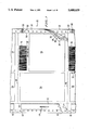
- FIG. 1 illustrates a portion of a connected strip 20 of multiple-ply shipping waybill forms 22 which may be assembled with the aid of an automatic verification or matching system of the type contemplated by the present invention.
- Each form 22 comprises five main paper plies or layers 24, 26, 28, 30 and 32 which are overlaid on each other and held together by alternating lines of adhesive (not shown) located at or near the left-hand edge of the form 22.
- the top ply 24, whose printed layout is similar to that of the remaining plies, contains a number of pre-printed blocks or spaces 34 which contain instructions for the user of the form 22 and space for the insertion of information concerning the desired shipment.
- Each ply is also printed with a tracking number that is unique to each individual form 22 for allowing a lost or delayed shipment to be tracked by the shipping company.
- the tracking number appears as a bar code 36 in the upper right-hand area of the top ply 24, and the same number appears in the form of human-readable digits 38 located just below the bar code 36. It will be understood that each of the remaining plies 26, 28, 30 and 32 contains the same bar code 36 and human-readable digits 38 at the same locations. Thus, when the plies 24-32 are detached from each other during the various stages of a shipment, the tracking number on any given ply will allow the status of the shipment to be monitored.
- each form 22 includes a sixth ply in the form of a narrow, wax-coated strip 40 that is secured by means of an adhesive along the left-hand edge of the form.
- the strip 40 serves as a release layer for carrying a pressure-sensitive label 42.
- the label 42 is imprinted in human-readable digits 44 with the same tracking number represented by the bar code 36 and digits 38.
- the label 42 is provided for the purpose of allowing a record to be kept of a shipment represented by the form 22 without manually transcribing the tracking number or removing one of the main plies 24-32. For example, delivery personnel can confirm that a shipment has been delivered by peeling off the label 42 and securing it to a delivery list.
- the strip 20 in FIG. 1 is separated into individual forms 22 by means of transverse lines of perforations 46 and 48.
- the strip is also provided with two longitudinal rows of punched holes 50 and 52, one along each lateral edge of the strip, for allowing the plies 24-32 of the strip 20 to be advanced by a standard pin band collator as will be described shortly.
- the holes 50 and 52 also allow the strip 20 to be loaded into a form-feed printer after finished forms 22 have been produced, in order to print standard or recurring information in the blocks or spaces 34.
- Carbonless ink technology can be employed to allow information written or typed in the blocks or spaces 34 of the top ply 24 to be duplicated in the corresponding spaces of the lower plies 26-32, or intervening layers of carbon paper (not shown) can be used for this purpose.
- longitudinal lines of perforations 54 and 56 are provided along the edges of the strip 20 to allow the main portions of the plies 24-32 to be separated from the edge portions containing the holes 50 and 52 and release strip 40.
- the perforations 46, 48, 54 and 56 are preferably formed through all of the plies 24-32 at once after the multiple-ply strip 20 has been assembled by a pin band collator. If individually cut and stacked forms 22 are desired, the transverse perforations 46 and 48 are replaced by cuts formed completely through the plies 24-32 of the strip 20.
- a registration mark 58 preferably consisting of a small rectangle printed in black ink at the right-hand edge of the top ply 24, is provided to indicate the position of each form 22 on the collator.
- the registration mark 58 is located at a known distance from the top or leading edge of the form (i.e., from the point where the line of perforations 46 will be formed) in the feed direction of the collator. In the illustrated embodiment, the feed direction is represented by the arrow 59 in FIG. 1.
- FIG. 2 is a diagrammatic overhead view of a printing and collating system 60 which may be used to produce multiple-ply forms 22 of the type illustrated in FIG. 1.
- the system 60 includes five unwind stands 62, 64, 66, 68 and 70, one for each of the plies 24, 26, 28, 30 and 32, respectively, of the assembled form 22.
- Each of the unwind stands 62-70 serves as a mounting fixture for dispensing the corresponding one of the plies 24-32 from a pre-printed roll (not shown). From the unwind stands 62-70, each of the plies 24, 26, 28, 30 and 32 is fed to a corresponding print engine 72, 74, 76, 78 and 80, respectively.
- the function of the print engines 72-80 is to apply the desired variable indicia (i.e., the bar code 36 and human-readable digits 38) to each of the plies 24-32 at the position shown in FIG. 1. Registration marks (not shown) similar to the registration mark 58 may be provided on each of the plies 24-32 for triggering the print engines 72-80 to print at the proper places on the respective plies.
- the print engines 72-80 may be of any desired type, but preferably comprise Series 400 or 700 Varypress magnetographic printers manufactured by Nipson Printing Systems of Belfort, France.
- These devices are controlled by digital inputs on lines 81 from external computers (not shown), and operate by forming latent magnetic images on a metal drum, developing the images with a toner composition, electrostatically transferring the developed toner images to the respective plies 24-32, and heat-fusing the toner images after transfer to the plies.
- Magnetographic printers have few moving parts and are reliable in operation, and hence they are well suited to high-volume variable printing applications.
- the print engines 72-80 may employ other types of printing technologies with which variable indicia can be printed, such as ion deposition printing, laser printing, ink jet printing and indexed mechanical printing.
- a suitable ion deposition printer for example, is the Model 2460, X150 or Presidex 650 print engine manufactured by Delphax Systems of Mississagua, Ontario, Canada.
- the type of print engine selected will generally be determined by cost constraints and required image resolution, but other types of constraints (such as the need to avoid the pressure fusing step used in ion deposition printers when the plies 24-32 are coated with carbonless ink microcapsules) may require the use of one printing technology in lieu of another.
- the plies 24-32 which emerge from the print engines 72-80, respectively, have been printed with the desired variable information in the form of the bar code 36 and human-readable digits 38 shown in FIG. 1.
- the plies 24-32 are fed to a pin band collator 82 which assembles the plies into a strip 20 of connected multiple-ply forms 22 of the type shown in FIG. 1 by overlaying the plies onto each other and securing them together at one edge with an adhesive.
- a diagrammatic side view of the collator 82 is provided in FIG. 3.
- the collator 82 is conventional in construction and need not be described in detail.
- the collator 82 comprises a series of stations 84, 86, 88, 90 and 92 which receive the individual plies 24, 26, 28, 30 and 32, respectively.
- the upstream station 92 which receives the lowermost ply 32 from the unwind stand 70
- the ply 32 is initially routed beneath the collator 82 and then travels vertically upward to emerge from a slot (not shown) in the side wall of the collator. From the slot, the ply 32 is turned 90° by a turn bar 96 so that it is aligned in the feed direction of the collator 82, and is then fed to the working surface of the collator 82 by means of guide and feed rollers 98 and 99.
- Additional rollers which have not been shown for simplicity, assist in guiding the motion of the ply 32 through the collator 82.
- the pin bands 100 and 102 consist of endless metal strips with short, vertically projecting pins for engaging the plies to be assembled.
- the pin bands 100 and 102 are driven continuously at a uniform velocity and serve as a transport system for conveying the plies 24-32 between successive stations 84-92 of the collator.
- the lowermost ply 32 of the form 22 is engaged with the pin bands 100 and 102, and at the next station 90 the ply 30 is overlaid onto the ply 32 and engaged with the pin bands.
- An adhesive applying nozzle (not shown) located between the stations 90 and 92 applies a glue or adhesive to one edge of the lowermost ply 32 before it is overlaid by the next upper ply 30, so that the plies will remain attached once they are brought into contact.
- This series of events is repeated for each successive downstream station 88, 86 and 84, with the result that the remaining plies 28, 26 and 24 are successively overlaid and bonded to the previous plies to produce the finished multiple-ply strip 22 of FIG. 1.
- the collator 82 of FIG. 2 is provided with a sixth station 104 for dispensing the strip 40 and pre-printed labels 42 from a roll 106.
- assembly of the multiple-ply forms 22 is substantially complete except for cutting and perforating.
- the assembled multiple-ply strip 20 is fed to a final processing station (not shown) which forms the longitudinal perforations 54 and 56 of FIG. 1 and divides the strip 20 into individual forms 22.
- the latter step may consist of forming the transverse perforations 46 and 48 of FIG. 1 if connected forms are desired, or of cutting completely through the strip 20 along the lines 46 and 48 if individually cut and stacked forms are desired.
- the strip 20 produced at the downstream end of the collator 82 will consist of mismatched plies and will be useless for its intended purpose.
- a ply matching error resulting from these and other causes can be quickly detected and corrected by providing the collator 82 with a plurality of indicia sensing devices, one located at each of the stations 84-92 and 104.
- the indicia sensing devices provided at the stations 84, 86, 88, 90 and 92 comprise bar code scanners 110, 112, 114, 116 and 118, respectively.
- Each of the bar code scanners 110-118 is positioned above one of the plies 24-32 so that it can scan the bar codes 36 on that particular ply before the ply is overlaid by the ply introduced at the next station.
- the indicia sensing device comprises a video camera 120 rather than a bar code scanner.
- the video camera is positioned above the strip 20 of assembled plies near the edge at which the release strip 40 has been applied, so that the human-readable digits 44 on the labels 42 are within the field of view of the camera.
- a control system (not shown in FIGS. 2 and 3) is connected to the bar code scanners 110-118 and video camera 120 in order to trigger the operation of these imaging devices at the proper times, and to store their outputs for verification or matching purposes.
- each visual indicator comprises a pair of incandescent lamps 134 and 136 with red and yellow lenses, respectively. Illumination of the red lamp 134 by the control system indicates that a matching or sequence error has occurred at the corresponding station, while illumination of the yellow lamp 136 indicates that the indicia being read at the station (i.e., a bar codes 36 or the human-readable digits 44) is either of poor quality or completely unreadable.
- the source of a matching or sequence error is quickly made apparent to the collator operator.
- the operator can be provided with early warning of conditions which may require attention. For example, toner clumps in the print engines 72-80 of FIG. 2 may result in bar codes 36 which, while scannable, give the final product a poor appearance. This situation will not necessarily result in a matching or sequence error, but the illumination of the yellow warning lamp 136 will alert the operator to the problem so that any necessary corrections can be made.
- the pin bands 100 and 102 are mounted on pulleys 138 and 140 located at either end of the collator 82.
- the pulleys are driven by a shaft 142 which forms a part of the drive system (not shown) for the collator 82.
- the shaft 142 is coupled to an angular resolver 144 and also to a shaft encoder 146.
- the resolver 144 allows the control system to produce appropriate synchronization signals for the bar code scanners 110-118
- the encoder 146 allows the control system to produce synchronization signals for the video camera 120.
- the resolver 144 and encoder 146 serve as motion sensors for detecting the velocity and displacement of the pin bands 100 and 102, and hence of the individual webs or plies 24-32 and release strip 40 carried by the collator 82. Proper synchronization also requires that the precise position of each form 22 be known as it advances through a given one of the stations 84-92 and 104. This is achieved by means of a photoelectric detector 148, which is mounted near the downstream or output end of the collator 82 and positioned to detect the registration marks 58 on the edges of the form strip 20.
- the detection of the registration marks by a single photoelectric detector 148 at a known location provides an indication of the relative position of each form 22 at the respective stations 84-92 and 104.
- This information together with the information provided by the resolver 144 and encoder 146, allows the bar code scanners 110-118 and video camera 120 to be triggered at the proper times.
- a solenoid-controlled spray unit 150 is located at the downstream end of the collator 82.
- the purpose of the spray unit 150 is to deposit a red dye on forms 22 with mismatched plies or other defects, before the forms 22 are perforated or cut by the final processing station 108.
- the spray unit 150 is actuated by the control system whenever a matching or sequence error occurs (i.e., whenever the red error lamp 134 is illuminated at one or more of the stations 84-92 and 104). This allows defective forms to be accurately identified and discarded after an error has occurred, without the need to discard forms which may not in fact contain errors.
- spray unit 150 allows for the possibility of correcting matching or sequence errors without stopping the collator 82 to remove the defective portion of the strip 20, since the defective products can easily be identified later on after the error has been corrected. Correction of matching or sequence errors "on the fly” may result in a greater number of defective forms being produced, but this may be a less serious consequence than the down time that results when the collator 82 must be stopped and restarted.
- FIG. 4 is a detailed perspective view illustrating the manner in which the bar code scanner 110 is mounted on the collator 82 at the station 84. It will be understood that the remaining bar code scanners 112-118 are mounted similarly at the respective stations 86-92. As shown, the bar code scanner 110 is affixed to a vertical bar 152 which forms a part of a mounting bracket 154. The vertical bar 152 is slidable along a horizontal bar 156 which extends parallel to the feed direction of the form strip 20, and is held in place by means of a screw-type clamp 158. This allows the bar code scanner 110 to be adjusted back and forth along the feed direction of the form strip 20.
- the horizontal bar 156 is, in turn, slidably mounted on a vertical bar 160 and held in place by a second screw-type clamp 162. By adjusting the position of the horizontal bar 156 with respect to the vertical bar 160, the height of the bar code scanner 110 above the form-strip 20 can be adjusted.
- the vertical bar 160 is slidably mounted on a horizontal bar 164 which extends transversely across the width of the collator, and is held in place by a third screw-type clamp 166. By sliding the vertical bar 160 with respect to the horizontal bar 164, the transverse position of the bar code scanner 110 with respect to the form strip 20 can be adjusted.
- Vertical supports 168 and 170 are attached to the side plates 172 and 174, respectively, of the collator 82 and serve to support the horizontal bar 164 at a desired height above the form strip 20.
- FIG. 5 illustrates the manner in which the same type of mounting bracket 154 is used to support the video camera 120 at the collator station 104.
- a strobe light unit 176 is mounted next to the video camera 120 to freeze the image on the continuously moving form strip 20. This allows the video camera 120 to obtain a clear image of the digits 44 on the release strip 40 even if its exposure time is relatively long in comparison to the rate of movement of the form strip 20. However, if the exposure time of the video camera 120 is sufficiently short, the strobe light unit 176 can be deleted.
- FIG. 5 Also illustrated in FIG. 5 are the photoelectric detector 148 and spray unit 150 of FIGS. 2 and 3. Appropriate brackets or mounting devices (not shown) are provided for these devices.
- the photoelectric detector 148 is positioned along the right-hand side of the form strip 20 in FIG. 5, so that it will detect the registration marks 158 as they pass below it.
- the spray unit 150 may be positioned as desired in order to apply a line of colored dye or ink along the middle or any other desired portion the form strip 20 before the strip is discharged from the collator 82.
- FIG. 6 illustrates an optional arrangement in which a bar code scanner 110, video camera 120 and strobe light unit 176 are all mounted on the same bracket 154.
- this arrangement is not used in the printing and collating system 60 shown in FIGS. 2 and 3, it may be desirable in cases where a ply containing two separate variable indicia printed at different times and/or by different printing devices is introduced at one of the stations of the collator 82. In this situation, the use of two separate imaging devices at the same collator station allows the two indicia to be compared as the ply is being introduced to the collator 82, so that an incorrectly printed ply can be detected before it is assembled with other plies.
- FIG. 7 is a block diagram of the principal electrical components of the verification or matching system in accordance with a preferred embodiment of the present invention. Except for the bar code scanners and other components already described as being mounted on the collator 82, most of the components shown in FIG. 7 are housed in a remote cabinet which is connected to the collator 82 by means of appropriate cables.
- Overall system control is provided by an industrial computer 182, which may comprise a Series 5000 rack mount computer manufactured by Cormark Corporation of Medfield, Mass. and equipped with an Intel 486 or 586 processor operating at 66 MHz.
- the computer 182 is connected to a keyboard 184 and video display terminal 186, which are preferably located in the remote cabinet to allow an operator to perform initial set-up operations and to monitor system status and error conditions.
- a second keyboard 188 and video display terminal 190 are located outside the cabinet at a point on or near the collator 82, so that they are conveniently accessible to the collator operator.
- Outputs from the computer 182 are connected to a rack 192 of solid state relays which operate certain components mounted on the collator 82. These include the visual indicators 122-132, the spray unit 150, a run lamp 193 which is illuminated whenever the system is in operation, and a buzzer 194 which alerts the collator operator in the event that a matching or sequence error is detected.
- the computer 182 is also connected to an interface circuit 196, to be described in more detail in connection with FIGS. 8-10.
- the interface circuit 196 receives inputs from the computer 182, from the encoder 146 of FIG.
- the interface circuit 196 receives additional inputs from a multiple-channel electronic limit switch 198 which is connected to the resolver 144 of FIG. 3, and from a programmable counter 200 which operates in conjunction with the encoder 146.
- the electronic limit switch 198 comprises a Model M1051 PLS 16-channel device manufactured by Autotech Controls of Carol Stream, Ill.
- the programmable counter 200 comprises a Max Position 1 4-channel unit manufactured by Danachef Controls of Gurnee, Ill.
- One output channel of the electronic limit switch 198 is used for each of the bar code scanners connected to the system, and one output channel of the programmable counter 200 is used for each video camera.
- Outputs from the interface circuit 196 are connected to five bar code scanner control units 202, 204, 206, 208 and 210, one corresponding to each of the bar code scanners 110, 112, 114, 116 and 118 of FIG. 3. Provision is also made for connecting a sixth control unit 211 to the interface circuitry 196 in order to accommodate a sixth bar code scanner 212, in case an additional scanner is needed in certain applications.
- Each control unit 202-211 is connected to its respective bar code scanner by means of a cable 213 extending between the remote cabinet and the collator 82, and functions both to control the operation of the scanner and to decode the scanner output data.
- the bar code scanners 110-118 and 212 comprise Scanstar Model 10 laser diode scanners manufactured by Computer Identics Corporation of Canton, Mass.
- the control units 202-211 comprise Scanstar Model 242i decoders manufactured by the same company.
- the bar code data decoded by the control units 202-211 is applied as input data to the computer 182 via lines 215 as shown in FIG. 7.
- the interface circuit 196 of FIG. 7 also provides trigger signals for the video camera 120.
- the interface circuitry preferably provides outputs for two additional video cameras 214 and 216.
- the video cameras 120, 214 and 216 may be of any desired type, but preferably comprise charge-coupled device (CCD) array cameras with either one or two dimensional CCD arrays.
- the video cameras 120, 214 and 216 comprise Model TI-324A two dimensional CCD array cameras manufactured by NEC America, Inc. of Irving, Tex., with type 05 modifications to interlace the two scan fields and thereby improve image resolution at high web speeds.
- the video cameras 120, 214 and 216 are connected to the computer 182 and to the interface circuit 196 by means of a frame grabber board 217, which preferably comprises a Data Raptor VL data acquisition board manufactured by Bit Flow, Inc. of Woburn, Mass.
- the frame grabber board 217 also triggers the strobe light unit 176 for the video camera 120 and similar strobe light units 219 and 221 for the video cameras 214 and 216, respectively.
- the frame grabber board will normally be provided as a plug-in board within the computer 182.
- the computer 182 also includes suitable optical character recognition (OCR) hardware and software for processing images produced at the camera outputs and received by the frame grabber board 217.
- OCR optical character recognition
- An example of a suitable OCR hardware/software package is the Textpert system available from CTA Corporation of New Haven, Conn., which is capable of processing up to 40,000 alphanumeric characters per minute. This is more than sufficient for recognizing the characters 44 in the labels 42 of FIG. 1 at the web speeds contemplated by the present invention.
- the computer 182 also includes suitable memory for storing the programming required for the operation of the verification system, input/output boards for establishing connections to the solid state relay rack 192 and interface circuit 196, and communication ports for receiving data from the bar code scanner control units 202-212 and video cameras 120, 214 and 216. These components are conventional and have been omitted from FIG. 7 in the interest of simplicity.
- FIG. 7 Also shown in FIG. 7 is an optional print engine and collator interface 223 which is connected to the computer 182. In instances where it is desired to resequence the print engines 72-80 automatically after a matching or sequence error has been detected, the print engine and collator interface 223 allows the collator 82 to be placed in a jog mode while the necessary correction data is sent to the computers (not shown) which control the print engines 72-80.
- Another optional component that is shown in FIG. 7 is an image present sensor 225, which may be connected to the interface circuit 196 (or, in some cases, directly to the computer 182).
- the image present sensor 225 may be mounted at one or more of the collator stations 84-92 and 104 to determine whether an image (e.g., a bar code 36 or digits 44) is present at a predetermined position in the form strip 20, without actually scanning or decoding the image.
- the image present sensor 25 is useful in instances where the detection of a blank or unprinted form ply (i.e., a ply which has not been printed with any variable information) is all that is needed at a particular collator station.
- the image present sensor may consist of a photoelectric detector and amplifier similar to the components 148 and 197, appropriately calibrated to detect the presence or absence of a printed image on the form strip 20.
- FIG. 8 is a schematic diagram of a portion of the interface circuit 196 which provides inputs to one of the bar code scanner control units 202-212.
- a START signal (whose origin will be described shortly in connection with FIG. 9) appears on an input line 220 whenever a registration mark 58 on the form strip 20 is detected by the photoelectric detector 148.
- the START signal is applied to the CLOCK input of a D-type latch or flip-flop 222 and causes the Q output of the latch to transition to a high logic level.
- the second input of the AND gate 226 is connected to one output channel 228 of the electronic limit switch 198 of FIG.
- the output 234 of the AND gate 226 is connected to the input 236 of the bar code scanner control unit by means of a further inverter 238.
- the first detection of a registration mark 58 by the photoelectric detector 148 will give rise to the START and ENASCAN signals, causing one input of the AND gate 226 to transition to a high logic level.
- the other input of the AND gate 226 is not brought high until an input in produced on line 228 by the electronic limit switch 198.
- the electronic limit switch 198 reaches its programmed "off" position for the output channel in question, at which point the input signal is removed from the line 228 and the AND gate 226 is disabled, causing the scanner control unit to stop decoding the data produced by the bar code scanner.
- the programmed "off" position of the electronic limit switch 198 (also pre-set by the operator) is set to correspond to the trailing edge of the bar code 36 that has Just been scanned.
- the bar code scanner control unit is enabled for the proper interval to allow complete scanning of the bar code 36.
- the computer 182 provides a low logic level /SYSRST signal on line 240 during initial power-up to initialize the scanning procedure. This signal is applied to the CLEAR input of the latch 222. This insures that the ENASCAN signal is not produced on line 224 until a START signal is received on line 220, and thus prevents premature triggering of the bar code scanner. Only a single latch 222 is required for all of the bar code scanners 110-118 and 214, but the remaining components shown in FIG. 8 are duplicated for each of the bar code scanners used in the system.
- FIG. 9 is a schematic diagram of a portion of the interface circuit 196 of FIG. 7 which receives inputs from the photoelectric detector 148 and photoelectric amplifier 197.
- an input signal from the photoelectric amplifier 197 appears on line 242 and is applied through two inverters 244 and 246 to one input of an AND gate 248.
- the other input of the AND gate 248 is connected to an input line 250 which receives a signal referred to as STRTSCAN from the computer 182.
- the STRTSCAN signal is continuously produced after the operator places the system in the RUN mode using a menu which appears on one of the display monitors 186 or 190 of FIG. 7.
- the AND gate 248 is enabled whenever the STRTSCAN signal and the occurrence of a registration mark 58 at the photoelectric detector 148 coincide.
- CLOCK inputs are applied by the AND gate 248 and a second AND gate 249 to a pair of latches 252 and 254, thereby producing and latching the START signal at the Q output of the latch 254.
- the START signal is applied to the trigger input of a one-shot multivibrator 256, which responds by producing an output pulse of predetermined duration at its Q output.
- the output pulse is applied through an OR gate 258 and inverter 260 to an output line 262.
- the output line 262 is connected to the reset input of the programmable counter 200 of FIG. 7, and serves to reset the accumulated count to zero.
- the START signal at the Q output of the latch 254 is also applied to one input of an AND gate 264, the second input of which receives pulses from the shaft encoder 146 of FIG. 7 through an inverter 266. These pulses appear at the output of the AND gate 264 whenever the START signal latched by the latches 252 and 254 is present, as will be the case after a registration mark 58 has been detected by the photoelectric detector 148. From the output of the AND gate 264, the encoder pulses are applied to the input of an inverter 268. The output line 270 of the inverter 268 is connected to the pulse counting input of the programmable counter 200 in FIG. 7.
- output pulses from the encoder 146 will be counted by the programmable counter 200 beginning with the detection of a registration mark 58 by the photoelectric detector 148, and the accumulated count will represent the distance traveled by the form strip 20 from the point at which the registration mark was detected.
- the video camera 120 is triggered when the programmable counter 200 reaches a preset count (determined by the operator during initial set-up) that corresponds to a position of the form strip 20 at which the digits 44 on the label 42 are within the field of view of the video camera 120.
- the pulse output on line 270 will continue until the latches 252 and 254 are cleared, which removes the START signal and disables the AND gate 264.
- the latches 252 and 254 are cleared by means of an AND gate 272, which receives as one input the/SYSRST input from the computer 182 and as a second input a momentary low logic level signal referred to as /RESET1 that occurs on an input line 274.
- the /RESET1 signal originates from the programmable counter 200, as will be discussed shortly in connection with FIG. 10, and its occurrence signifies that the collator shaft 142 has rotated by an amount corresponding to the length of one form 22 at the pin bands 100 and 102.
- the output of the AND gate 272 goes low and clears the latches 252 and 254.
- the RESET1 signal is also applied to one input of an AND gate 276, the other input of which receives the/SYSRST signal from the computer 182 through inverters 278 and 280.
- the output of the AND gate 276 on line 282 is driven low and triggers the negative trigger input of a one-shot multivibrator 284.
- the Q output of the one-shot multivibrator 284 is connected to the second input of the OR gate 258.
- the output of the inverter 246 in FIG. 9 is connected to an output line 288 via a current sourcing device 290.
- the output line 288 is connected to the reset cycle input of the electronic limit switch 198 in FIG. 7, and causes the electronic limit switch 198 to begin counting toward its programmed "on” and “off” settings with every registration mark 58 that is detected by the photoelectric detector 148.
- the line 288 is connected to the ModZ input of the electronic limit switch.
- a separate "on” and “off” setting is programmed by the operator for each of the bar code scanners 110-188 and 214, and corresponds to the arrival of the leading and trailing edges, respectively, of one of the bar codes 36 at the scanner in question.
- the output of the inverter 246 is also applied to one input of an AND gate 292, the other input of which receives the ENASCAN signal from the interface circuitry of FIG. 8.
- the output of the AND gate 292 is connected through an inverter 294 to an output line 296.
- the output line 296 is connected through an RS-232 driver (not shown) to the computer 182 of FIG. 7, and provides a signal to the computer to indicate that a registration mark 58 has been detected by the photoelectric detector 148. This triggers an interrupt in the computer 182 which allows the computer 182 to keep track of each successive form 22.
- FIG. 10 is a schematic diagram of a portion of the interface circuit 196 which receives outputs from the programmable counter 200 of FIG. 7.
- the programmable counter 200 has a number of output channels, each of which can be controlled separately when the counter reaches a predetermined count.
- One of these channels is represented by the input line 298 in FIG. 10, which is connected through an inverter 299 to the trigger input of a one-shot multivibrator 300.
- the one-shot multivibrator 300 produces a pulse of predetermined duration at its Q output 302.
- the Q output of the one-shot multivibrator 300 is connected through an inverter 308 to an output line 310 that produces a signal of fixed duration designated/TRIG1.
- the output line 310 is connected to the frame grabber board 217 of FIG. 7, and causes the video camera 120 to produce an output representing the image in the camera frame at the moment that the /TRIG1 signal appears.
- the Q output of the one-shot multivibrator 300 also produces a/CAM1INT signal on line 312, which provides an input to the computer 182 via the RS-232 driver referred to earlier.
- The/CAM1INT signal generates an interrupt which causes the software of the computer 182 to respond by selecting the video camera 120 and triggering the frame grabber board 217 to acquire the image at the camera output.
- The/CAM1INT signal is also applied to the CLOCK input of a latch 314, causing the Q output of the latch 314 to transition to a high logic state on the positive transition of/CAM1INT.
- RDYCAM1 This produces a signal referred to as a RDYCAM1 on line 316, which provides an input to the computer 182.
- the RDYCAM1 signal identifies the video camera 120 as the particular camera which has been triggered, and signals the computer 182 to receive an image from the frame grabber board 217. After the image from the video camera 120 has been received and processed by the computer 182, the computer produces a signal referred to as /RSTCAM1 on an input line 318. This signal is applied to one input of an AND gate 320, the other input of which receives the ENASCAN signal from the circuitry of FIG. 8.
- the AND gate 320 is enabled and a signal is applied to the CLEAR input of the latch 314 via line 324. This causes the RDYCAM1 signal to be removed from the output line 316, thereby preparing the circuit for another operating cycle.
- the one-shot multivibrator 300 is reset by the occurrence of the /RESET2 signal (produced by the circuitry of FIG. 9) on an input line 326. Since the /RESET2 signal is produced in response to a /SYSRST signal from the computer 182, this insures that the one-shot multivibrator 300 is not inadvertently triggered at the moment of system start-up.
- one of the output channels of the programmable counter 200 produces a signal on an input line 328 when a count representing the length of one form 22 has been accumulated.
- This signal is applied via an inverter 330 to the trigger input of a one-shot multivibrator 332.
- the Q output of the one-shot multivibrator 332 produces the /RESET1 signal of FIG. 9 on output line 334, which is used to reset the count of the programmable counter 200 to zero.
- the components of FIG. 10 are duplicated for each of the video cameras 120, 214 and 216 of FIG. 7. The maximum number of video cameras will depend upon the number of output channels available on the programmable counter 200.
- FIG. 11 is a flow chart illustrating the manner in which the computer 182 of FIG. 7 is programmed to control the verification of matching operation.
- a power-up routine is executed during which various initialization and diagnostic tasks are performed.
- the computer proceeds to block 342 allocates a section of memory to be used for storing output data from the bar code scanners 110-118 and 214 and video cameras 120, 214 and 216.
- the manner in which this section of memory is organized is shown diagrammatically in FIG. 12 for the video camera 120 and three of the bar code scanners 110-118, and it will be understood that the same arrangement is employed for the remaining bar code scanners.
- the total number of bar code scanners and video cameras to be used is specified by the operator during initial set-up.
- the computer reserves in memory a recirculating first-in, first-out (FIFO) buffer having a number of storage locations equal to the number of forms 22 which are present on the collator 82 at any given time.
- FIFO first-in, first-out
- the FIFO buffers are configured as singularly linked lists, with each buffer location containing an index value, the scanner or camera data and a pointer indicating the next buffer location. The pointer in the last buffer location points to the first buffer location, thereby creating a recirculating queue that emulates the physical motion of the forms 22 along the collator 82.
- a similar FIFO buffer is maintained for the photoelectric detector 148, with each buffer location containing an index value and a pointer indicating the next location.
- the computer 182 also maintains global pointers, one for each FIFO buffer, which point to specific locations in the FIFO buffers that are used to store data received from the bar code scanners 110-118 and video camera 120 during operation of the verification or matching system.
- the global pointers (indicated at P1, C1, S1, S2 and S3 in FIG. 12) are continually incremented using the pointer values stored in the FIFO buffers, but are separated by fixed displacement values that correspond to the physical separation between the bar code scanners and video cameras on the collator 82. With each detection of a registration mark 58 by the photoelectric detector 148, the computer simultaneously increments all of the global pointers to point to the next FIFO buffer location.
- the computer 182 proceeds to block 344 after having allocated the memory in the manner shown in FIG. 12.
- the individual memory locations in the FIFO buffers are initialized, and in block 346, the global pointers for each FIFO buffer are initialized.
- the computer 182 initializes all of the bar code scanners, video cameras and other external devices of FIG. 7 by sending appropriate signals to the solid state relay rack 192 and interface circuit 196.
- the computer 182 waits for the collator 82 to start, and repeatedly checks in block 352 to determine whether the collator is running. If so, the computer proceeds to decision block 354 and checks to determine whether a registration mark 58 has been detected by the photoelectric detector 148.
- the computer 182 checks to determine whether a ply matching error has occurred. This is preferably done in several different ways. First, assuming that all plies of the form are intended to contain identical indicia, the computer 182 checks to determine whether the data in all six of the FIFO device buffers is the same. If it is, the form 22 has been properly assembled; if not, an assembly error has occurred.
- the sound of the buzzer alerts the collator operator to the fact that an error has occurred, and the location of the illuminated red warning lamp directs the operator to the appropriate collator station so that the error can be corrected.
- errors may occur at more than one station simultaneously, and in such cases the red error lamps 134 at all of the involved stations are illuminated.
- the computer 182 proceeds to decision block 362 and checks the set-up data entered by the operator to determine whether a spray unit 150 has been provided. If so, the computer proceeds to block 364 and energizes the spray unit 150 in order to apply a red dye to the forms affected by the error. Operation of the spray unit 150 continues until the error condition disappears or until a manual reset input is applied to the computer 182 by the collator operator.
- the failure of the computer 182 to detect an error condition causes processing to proceed to a further decision block 366.
- the computer 182 checks an internal timer to determine whether the displays 186 and 190 should be updated.
- the displays 186 and 190 continually display the scanner and camera data from the FIFO buffers that are being used for the current comparison operation, together with a portions of the actual video image detected by the video camera 120.
- this information will change too quickly to be read by a human operator, and hence the computer 182 is programmed to update the displays 186 and 190 according to a predetermined schedule (e.g., every fifty forms).
- a predetermined schedule e.g., every fifty forms
- the computer 182 proceeds to decision block 370 and polls the bar code scanner control units to determine whether any scanner data is available. If so, the computer proceeds to block 372 checks the quality of the scanned bar code (and whether the code is missing entirely) by determining the number of successful scans which were made during the interval in which the bar code was within the field of view of the scanner. This is done by examining the prefix characters provided at the output of the bar code scanner control units 202-210.
- the bar code scanners used in the preferred embodiment of the present invention are capable of scanning each bar code 26 times as the bar code passes the scanner.
- the computer 182 illuminates the yellow warning lamp 136 at the collator station in question if any of these scans are unsuccessful.
- the computer 182 may be programmed to illuminate the yellow warning lamp if the check digits (provided at the output of the controllers 202-210 along with the bar code data) do not correspond with the detected bar code data. If a determination is made in block 372 that the bar code is present and of acceptable quality, the computer 182 proceeds to block 376 and stores the scanner data (i.e., the detected tracking number or other indicia) in the appropriate FIFO buffer location.
- the computer 182 After processing any available bar code scanner data, the computer 182 proceeds to decision block 378 and checks to determine whether any data is available from the video camera 120. If any data is available, the computer proceeds to block 380 and determines from the optical character recognition (OCR) software whether a readable image is present. If the OCR software is unable to process the data from the video camera 120 (e.g., because no image is present within the camera frame), or if the software diagnostics indicate that the output data is unreliable, a warning condition is present. This causes the computer 182 in block 382 to illuminate the yellow warning lamp 136 at the collator station 104 where the video camera is located.
- OCR optical character recognition
- the computer proceeds to block 384 and stores the video camera data (i.e., the tracking number of other indicia identified by the OCR software) in the appropriate FIFO buffer location. If the system is equipped with the optional image present sensor 225 of FIG. 7, the computer 182 then determines in block 386 whether the presence of an image has been detected, and if so, appropriate data is stored in an additional FIFO buffer location as indicated by block 388.
- video camera data i.e., the tracking number of other indicia identified by the OCR software
- decision block 352 manual stoppage of the collator 182 by the operator (e.g., in response to the occurrence of an error or warning condition) will cause a negative determination to be made in this block.
- the computer 182 proceeds to decision block 390 and determines whether the collator has recently stopped running. If not, the computer returns to block 350 and waits for the collator to be restarted. If the collator has recently stopped running, the computer diverts to block 392 and terminates all active data collection procedures by sending appropriate signals to the solid state relay rack 192 and interface circuit 196. The computer then returns to block 344 and repeats the various initialization operations described previously.
- the computer 182 may be programmed to automatically resequence the print engines 72-80 of FIG. 2 after a matching or sequence error has been detected. This is indicated in the flow chart of FIG. 11 by the additional block 384, which is executed by the computer following activation of the spray unit 150 in block 364. The action taken in block 394, to be described in more detail in connection with FIG. 14, will depend upon the nature of the error detected in decision block 358.
- the print engines 72-80 will be resequenced in the proper direction (i.e., numerically upward or downward) to begin printing forms 22 with matching tracking numbers which follow the tracking number of the last correctly printed form.
- Corresponding measures may be taken in cases where the tracking number on a particular ply has been duplicated on another form or is missing entirely.
- the automatic resequencing of the print engines 72-80 in block 382 may in some cases avoid the need to stop the collator 82 for manual re-registration when an error condition occurs. Defective forms produced while the error persists can be readily identified after the error has been corrected, as a result of the dye applied by the spray unit 150 in block 364 of the flow chart.
- any stoppage of the collator 82 following the occurrence of an error or warning condition is the result of manual action by the collator operator.
- this mode of operation is preferred, it is within the scope of the invention stop the collator automatically under control of the computer 182 following the occurrence of either type of condition.
- an error condition i.e., the detection of a form 22 with mismatched plies
- a warning condition caused by an inability to read one or more indicia on the plies may be temporary and may disappear spontaneously.
- the computer 182 may be programmed to stop the collator in response to the occurrence of an error condition (or a predetermined minimum number of successive error conditions) at a given one of the stations 84-92 and 104.
- FIG. 13 is a flow chart illustrating the manner in which the computer 182 determines whether a ply matching error has been detected in blocks 356-360 of FIG. 11.
- the computer determines the index number of the form 22 whose registration mark 58 has just been detected by the photoelectric detector 148 in block 354 of FIG. 11. This index number, which will correspond to the contents of the FIFO buffer location designated by the global pointer P1 in FIG. 12, is used to define the initial value of a parameter referred to as BILL -- NUM.
- the computer 182 initializes a parameter DEV -- CNT to zero.
- the computer 182 then proceeds to block 404, where a parameter CUR -- DEV is set to a value corresponding to the first device (i.e., the first bar code scanner or video camera) whose output is to be processed.
- the computer 182 uses the index number BILL -- NUM to obtain the output data from the first device by adding the value of BILL -- NUM to the first FIFO buffer address for the device in question and reading the output data stored at the FIFO buffer location. This data is stored at a memory location referred to as CUR -- DATA.
- a memory location designated BAD -- BILL -- CNT corresponding to the first device is accessed.
- a separate BAD -- BILL -- CNT storage location is reserved for each bar code scanner or video camera used in the system.
- the value of BAD -- BILL -- CNT for the first device is initialized to zero.
- the computer proceeds to decision block 412 of FIG. 13 and determines whether any data has been read from the FIFO buffer accessed in block 406. If so, the computer 182 proceeds to block 414 and increments the parameter DEV -- CNT.
- the computer 182 selects the first device for comparison with the data read in block 406. In the preferred embodiment of the invention, this is the same as the device selected in block 404; in other words, the data from the first device will be compared with itself during the first pass through the program loop.
- the output data from the device to be compared is obtained from the appropriate FIFO buffer of FIG. 12 using a procedure similar to that described above in connection with block 406.
- the resulting data is stored in a memory location referred to as COMP -- DEV.
- the computer 182 determines whether the values in the storage locations CUR -- DATA and COMP -- DATA match. If they do, the computer proceeds to a further decision block 422; if not, the computer increments the value of BAD -- BILL -- CNT in block 424 before proceeding to the decision block 422.
- the computer determines whether the FIFO buffer data for the first device has been compared with the FIFO buffer data for each of the remaining devices. If so, the comparison operation for the first device is complete and the computer proceeds to a further decision block 426. If not, the computer proceeds to block 428 and selects the next device for comparison.
- the program loop comprising blocks 418, 420, 422, 424 and 428 will then be repeated until the output data for the first device has been compared with the output data for all of the remaining devices.
- the computer proceeds to decision block 426 as described previously.
- the decision block 426 will be reached after the computer 182 has compared the output data from the video camera with the output data from each of the bar code scanners 110-118. If any of these comparisons do not result in a match, the value of BAD -- BILL -- CNT for the video camera 120 will have been incremented accordingly.
- the computer 182 proceeds directly to decision block 426 from decision block 412 in the event that no data was found in the FIFO buffer for the device in question.
- the computer determines whether the device for which all of the preceding comparisons have been made (i.e., the video camera 120 in the example) is the last device in the system. If not, the computer proceeds to block 430 and sets the parameter CUR -- DEV equal to a value that corresponds to the next device. Thus, assuming that the video camera 120 was the first device, the bar code scanner 110 may be selected as the next device in block 430. The computer then returns to block 406, and uses the index number BILL -- NUM to obtain the FIFO buffer data for the bar code scanner 110. The computer 182 then carries out the operations in blocks 408-416 and reenters the program loop that begins in block 418.
- the device for which all of the preceding comparisons have been made i.e., the video camera 120 in the example
- the output data from the bar code scanner 110 is taken as the reference data and is compared with the output data from the video camera 120 and bar code scanners 112-118. Depending upon the results of these comparisons, a value of BAD -- BILL -- CNT is computed for the bar code scanner 110.
- the computer returns again to decision blocks 426 and 430, and repeats the process for the remaining bar code scanners 112-118. At that point, all of the required comparisons have been made and value of BAD -- BILL -- CNT exists for each of the devices 110-118 and 120.
- the computer 118 calculates a parameter HALF -- DEV which is equal to one-half of the parameter DEV -- CNT rounded down to the nearest integer. In the illustrated system employing one video camera 120 and five bar code scanners 110-118, HALF -- DEV will be equal to three.
- decision block 434 the computer checks to determine whether the value of BAD -- BILL -- CNT is greater than zero for any of the devices 110-118 or 120. If not, there are no matching errors and the program routine is complete. However, if at least one of the stored values of BAD -- BILL -- CNT is greater than zero, the computer 182 proceeds to block 436 and activates the warning buzzer 194 of FIG. 7.
- the computer 182 then proceeds to decision block 438 and determines whether any of the stored values of BAD -- BILL -- CNT are equal to HALF -- DEV. This is done in order to determine whether the number of matching and non-matching plies are equal, a situation which makes it impossible to determine which plies (and collator stations) are in error. If this condition is found not to exist, the computer proceeds to block 440 and activates the red error lamp 134 at each of the collator stations 84-92 and 104 for which the corresponding bar code scanners 110-118 and video camera 120 have a BAD -- BILL -- CNT that is greater than HALF -- DEV.
- the computer displays an error indication on the video display terminals 186 and 190 of FIG. 7 for all devices with a BAD -- BILL -- CNT greater than HALF -- DEV. This supplements the information provided by the illumination of the red warning lamps 134, and allows the collator operator to quickly identify the collator stations where corrections need to be made.
- the computer 182 determines in decision block 438 that the value of BAD -- BILL -- CNT for any of the devices 110-118 or 120 is equal to HALF -- DEV, a deadlock situation exists in that the number of matching plies is equal to the number of non-matching plies. In that event, the computer proceeds to block 444 and checks the stored data (i.e., tracking number) for the last form 222 that did not contain any matching errors. From this data, the computer can infer which of the current plies are in error and which are correct. In block 446, the computer 182 sets the value of BAD -- BILL -- CNT to zero for each of the devices whose data-the computer has found to be correct.
- the stored data i.e., tracking number
- the computer increments the value of BAD -- BILL -- CNT by one for each device whose data the computer has determined not to be correct. With these reset values of BAD -- BILL -- CNT, the computer proceeds to block 440 and activates the red error lamps 134 at the collator stations where the errors are determined to have occurred. After displaying any errors on the video display terminals 186 and 190 in block 442, the matching routine in complete.
- FIG. 14 is a flow chart which illustrates the manner in which the computer 182 can automatically resequence the print engines 72-80 of FIG. 2 after a matching error occurs, as indicated by block 394 in FIG. 11.
- the computer proceeds to block 450 of FIG. 14 and changes the operating mode of the collator 82 from RUN to JOG.
- the reduced speed of the collator 82 in the JOG mode reduces product waste during the printer resequencing operation, that keeps the collator in operation so that adhesive drying and other problems arising from stoppage of the collator do not occur.
- operation of the print engines 72-80 is stopped to prevent any further variable information from being printed on the individual webs or plies 24-32.
- the computer 182 checks its memory to determine the page number of the last correctly printed form 22.
- the page numbers used by the print engines 72-80 correspond to the individual forms 22, with each page being defined by the presence of a registration mark on the particular ply or web 24-32.
- the computer then proceeds to block 456 and queries each of the print engines 72-80 to determine its current page number, and calculates new starting page numbers for each of the print engines.
- the new starting page numbers are transmitted to the respective print engines 72-80. Once the new starting page numbers have been transmitted, the computer restarts the print engines in block 460, and returns the collator to the RUN mode in block 462. At this point, the printer resequencing operation is complete.
- FIGS. 15-17 illustrate three representative display screens which are displayed by the computer 182 on the video display terminals 186 and 190 of FIG. 7.
- FIG. 15 illustrates a set-up screen which is used by the operator to configure the system for the desired number and location of bar code scanners and video cameras.
- the values shown under the column heading "Distance from Eye” represent the measured distance (in inches) along the collator 82 between the photoelectric detector 148 and each of the bar code scanners 110-118, the video camera 120, and the sprayer unit 150.
- a zero value has been specified for scanner 6 to indicate that only five bar code scanners 110-118 are present, as in the exemplary system illustrated in FIGS. 2 and 3. Similar zero entries (not shown) may be provided for the unused video cameras 214 and 216 of FIG. 7.
- the heading "COMM PORT” refers to input/output port assignments within the computer 182 for each of the bar code scanner control units 202-211 of FIG. 7.
- the value filled in next to the term “Gear” represents the amount of linear travel (in inches) of the collator pin bands 100 and 102 for each full turn of the collator shaft 142.
- FIG. 16 illustrates a run screen which is displayed to the operator while the collator 82 is in operation.
- the run screen displays the stored outputs, for a given one of the forms 22, from the bar code scanners and video cameras for which the system has been configured.
- the outputs from the bar code scanners 110-118 and video camera 120 (which are all the same in the absence of an error) are displayed as a single set of digit 464 representing the sensed bar codes 36 and label digits 44.
- a small window 466 representing a portion of the field of view of the video camera 120. The size and location of the window is established by the operator during initial system set-up.
- the data displayed to the operator is preferably updated at some fraction of the actual rate of form movement along the collator 82, since the display would otherwise change too quickly to be of any use to the operator.
- the display shown in FIG. 14 also includes a history of recent warning conditions at the bottom of the screen. If error conditions or collator stoppages occur, these are displayed in a similar manner.
- FIG. 17 illustrates an error screen which is displayed by the computer 182 wherever an error condition occurs that results in the illumination of one or more of the red warning lamps 134.
- the matching digits 464 on the run screen of FIG. 14 are replaced with an error message 468 which indicates the particular ply (i.e., collator station) that is in error, together with the erroneous tracking number detected on that ply.
- the computer 182 prints a more detailed error message 470 which lists the tracking numbers detected on all of the plies by the bar code scanners 110-118 and video camera 120.
- the display will include an error message 468 for each erroneous ply.
- the computer 182 may be programmed to generate other display screens or menus for various functions. These may include display screens for establishing the operating parameters of the bar code scanners, display screens for setting the video camera image window that is to be processed by the computer 182, display screens for setting communication parameters between the computer 182 and various external devices of FIG. 7, and display screens for certain diagnostic and housekeeping operations. These display screens will depend to some extent on the specific components used in the system, and have been omitted for simplicity.
Abstract
Description
Claims (45)
Priority Applications (6)
| Application Number | Priority Date | Filing Date | Title |
|---|---|---|---|
| US08/372,671 US5608639A (en) | 1995-01-13 | 1995-01-13 | System and method for printing, assembly and verifying a multiple-part printed product |
| CA002159537A CA2159537C (en) | 1995-01-13 | 1995-09-29 | Automatic verification system for multiple-part printed product |
| EP96903448A EP0829060A4 (en) | 1995-01-13 | 1996-01-16 | Automatic verification system for multiple-part printed product |
| PCT/US1996/000395 WO1996021904A1 (en) | 1995-01-13 | 1996-01-16 | Automatic verification system for multiple-part printed product |
| AU47536/96A AU4753696A (en) | 1995-01-13 | 1996-01-16 | Automatic verification system for multiple-part printed product |
| US08/740,121 US5915089A (en) | 1995-01-13 | 1996-10-24 | Supplemental data processing system for processing ply-matching data generated during multiple-part product printing |
Applications Claiming Priority (1)
| Application Number | Priority Date | Filing Date | Title |
|---|---|---|---|
| US08/372,671 US5608639A (en) | 1995-01-13 | 1995-01-13 | System and method for printing, assembly and verifying a multiple-part printed product |
Related Child Applications (1)
| Application Number | Title | Priority Date | Filing Date |
|---|---|---|---|
| US08/740,121 Continuation-In-Part US5915089A (en) | 1995-01-13 | 1996-10-24 | Supplemental data processing system for processing ply-matching data generated during multiple-part product printing |
Publications (1)
| Publication Number | Publication Date |
|---|---|
| US5608639A true US5608639A (en) | 1997-03-04 |
Family
ID=23469174
Family Applications (1)
| Application Number | Title | Priority Date | Filing Date |
|---|---|---|---|
| US08/372,671 Expired - Lifetime US5608639A (en) | 1995-01-13 | 1995-01-13 | System and method for printing, assembly and verifying a multiple-part printed product |
Country Status (5)
| Country | Link |
|---|---|
| US (1) | US5608639A (en) |
| EP (1) | EP0829060A4 (en) |
| AU (1) | AU4753696A (en) |
| CA (1) | CA2159537C (en) |
| WO (1) | WO1996021904A1 (en) |
Cited By (38)
| Publication number | Priority date | Publication date | Assignee | Title |
|---|---|---|---|---|
| US5732939A (en) * | 1994-08-17 | 1998-03-31 | Ferag Ag | Process for the continuous production of different types of printed products from different types of product parts |
| US5778783A (en) * | 1995-07-26 | 1998-07-14 | Heidelberger Druckmaschinen Ag | Sheet-fed printing press |
| US5915089A (en) * | 1995-01-13 | 1999-06-22 | Wallace Computer Services, Inc. | Supplemental data processing system for processing ply-matching data generated during multiple-part product printing |
| US5992973A (en) * | 1998-10-20 | 1999-11-30 | Eastman Kodak Company | Ink jet printing registered color images |
| US6049637A (en) * | 1997-08-12 | 2000-04-11 | Ncr Corporation | System and method for automated data capture of sequential form numbers at a collator/press assembly machine using an optical reader which does not capture an image of the form number |
| US6078698A (en) * | 1999-09-20 | 2000-06-20 | Flir Systems, Inc. | System for reading data glyphs |
| US6243618B1 (en) * | 1997-10-30 | 2001-06-05 | Honda Giken Kogyo Kabushiki Kaisha | Method of marking number or the like and apparatus for marking the same |
| US6266437B1 (en) * | 1998-09-04 | 2001-07-24 | Sandia Corporation | Sequential detection of web defects |
| EP1118566A1 (en) * | 2000-01-20 | 2001-07-25 | KAVANAGH, Conor | A method for the production and control of merging continuous webs with variable data thereon |
| US6499069B1 (en) * | 1996-01-16 | 2002-12-24 | Canon Kabushiki Kaisha | Interface apparatus and method, and image output apparatus having interface apparatus |
| US6529920B1 (en) | 1999-03-05 | 2003-03-04 | Audiovelocity, Inc. | Multimedia linking device and method |
| US20030112479A1 (en) * | 2000-10-12 | 2003-06-19 | Thomas Huber | Method for synchronizing a number of paper feeding channels of a paper processing system |
| US20030110739A1 (en) * | 2001-12-13 | 2003-06-19 | Winkler & Duennebier Ag | Method and apparatus for detecting product defects during the production of mailing products, hygiene products, or folded paper products |
| US6646280B1 (en) * | 1999-08-20 | 2003-11-11 | Koenig & Bauer Aktiengesellschaft | Device and method for inspecting and cutting strips of security documents |
| EP1380441A1 (en) * | 2002-07-09 | 2004-01-14 | Bell & Howell Mail And Messaging Technologies Company | System and method for multiple print stream management and finishing |
| US6729543B1 (en) | 1998-03-06 | 2004-05-04 | Audiovelocity, Inc. | Page identification system and method |
| US20040109752A1 (en) * | 2001-01-23 | 2004-06-10 | Tomoaki Hirako | Conveyor system |
| WO2004073999A1 (en) * | 2003-02-24 | 2004-09-02 | OCé PRINTING SYSTEMS GMBH | Printing system and method, control device, and computer program product comprising print data integrity monitoring |
| US20040218958A1 (en) * | 2001-09-24 | 2004-11-04 | Jurgen Kruger | Method and device for printing mail |
| US20050137743A1 (en) * | 2003-12-19 | 2005-06-23 | Ferag Ag | Control of an installation for gathering flexible products |
| US20060061029A1 (en) * | 2004-09-21 | 2006-03-23 | First Data Corporation | Sheet processing systems and methods |
| US7031020B1 (en) * | 1994-04-22 | 2006-04-18 | Canon Kabushiki Kaisha | Image processing method, apparatus and controller |
| US20060117977A1 (en) * | 2004-11-30 | 2006-06-08 | Oxy-Dry Maschinen Gmbh | Method and apparatus for cleaning cylinders of a printing press |
| US7130710B2 (en) | 2002-08-07 | 2006-10-31 | Kimberly-Clark Worldwide, Inc. | System and method for tracking and exploiting per station information from a multiple repeat manufacturing device |
| US20070249901A1 (en) * | 2003-03-07 | 2007-10-25 | Ohline Robert M | Instrument having radio frequency identification systems and methods for use |
| US20080151252A1 (en) * | 2006-12-20 | 2008-06-26 | National Envelope Corporation | Seal gum thickness measurement |
| US20080295724A1 (en) * | 2005-11-25 | 2008-12-04 | Volker Lohweg | Method For Detection Of Occurrence Of Printing Errors On Printed Substrates During Processing Thereof On A Printing Press |
| US20090003916A1 (en) * | 2007-06-29 | 2009-01-01 | Xerox Corporation | Systems and methods for printing multi-layer documents |
| US20090025522A1 (en) * | 2007-07-26 | 2009-01-29 | Sven Erler | Method and device for optimizing transverse machining operations |
| US20090084854A1 (en) * | 2007-09-27 | 2009-04-02 | Symbol Technologies, Inc. | Multiple Camera Imaging-Based Bar Code Reader |
| US20100001075A1 (en) * | 2008-07-07 | 2010-01-07 | Symbol Technologies, Inc. | Multi-imaging scanner for reading images |
| US20100051706A1 (en) * | 2008-09-03 | 2010-03-04 | James Harrison Pagones | Sealed cards and methods of producing the same |
| US8121868B1 (en) | 2004-09-10 | 2012-02-21 | James Grady | Systems and methods for providing an inducement to purchase incident to a physician's prescription of medication |
| DE102012105338A1 (en) * | 2012-06-20 | 2013-12-24 | Océ Printing Systems GmbH & Co. KG | Method for controlling e.g. electrophotographic printing system that is utilized for printing of paper web, involves continuing printing process, repeating error elimination module and stopping digital printing system based on test result |
| US8781848B1 (en) | 2004-09-10 | 2014-07-15 | Ldm Group, Llc | Systems and methods for providing an inducement of a purchase in conjunction with a prescription |
| US20150013269A1 (en) * | 2011-10-17 | 2015-01-15 | R. J. Reynolds Tobacco Company | Cigarette package coding system and associated method |
| US9053413B2 (en) | 2013-07-22 | 2015-06-09 | Xerox Corporation | Automatically identifying locations of printing defects within printed rolls |
| CN109655470A (en) * | 2018-12-27 | 2019-04-19 | 陕西东方航空仪表有限责任公司 | Bar code printing quality intelligent detection system |
Families Citing this family (1)
| Publication number | Priority date | Publication date | Assignee | Title |
|---|---|---|---|---|
| DE102013104209A1 (en) * | 2013-04-25 | 2014-10-30 | Wemhöner Surface Technologies GmbH & Co. KG | Method and device for the exact laying of coating material on to be coated in a press carrier plates |
Citations (3)
| Publication number | Priority date | Publication date | Assignee | Title |
|---|---|---|---|---|
| US4574692A (en) * | 1983-10-05 | 1986-03-11 | Gretag Aktiengesellschaft | Process and apparatus for the preparation of photographic copies |
| US5033725A (en) * | 1989-05-25 | 1991-07-23 | Svecia Antiqua Limited | Method of checking and combining separate documents or part documents of the letter and envelope type |
| US5067088A (en) * | 1990-02-16 | 1991-11-19 | Johnson & Quin, Inc. | Apparatus and method for assembling mass mail items |
Family Cites Families (7)
| Publication number | Priority date | Publication date | Assignee | Title |
|---|---|---|---|---|
| US4707790A (en) * | 1985-11-21 | 1987-11-17 | Pitney Bowes Inc. | Control signal buffer for use in an inserter system |
| US5028040A (en) * | 1990-01-08 | 1991-07-02 | Moore Business Forms, Inc. | Apparatus and methods for verifying registration of form parts and forms therefor |
| DE4012396A1 (en) * | 1990-04-19 | 1991-10-31 | Roland Man Druckmasch | PRINTING MACHINE |
| US5179522A (en) * | 1990-06-07 | 1993-01-12 | Pitney Bowes Inc. | Scanning method and apparatus for an inserter |
| US5191540A (en) * | 1990-09-05 | 1993-03-02 | Pitney Bowes Inc. | Sheets processing apparatus including memory means removably connected thereto |
| US5117610A (en) * | 1990-09-21 | 1992-06-02 | Dittler Brothers, Incorporated | Methods and apparatus for printing and collating materials from multiple webs |
| US5317654A (en) * | 1991-09-26 | 1994-05-31 | Inscerco Mfg. Inc. | Selective collating and inserting apparatus |
-
1995
- 1995-01-13 US US08/372,671 patent/US5608639A/en not_active Expired - Lifetime
- 1995-09-29 CA CA002159537A patent/CA2159537C/en not_active Expired - Fee Related
-
1996
- 1996-01-16 EP EP96903448A patent/EP0829060A4/en not_active Withdrawn
- 1996-01-16 WO PCT/US1996/000395 patent/WO1996021904A1/en not_active Application Discontinuation
- 1996-01-16 AU AU47536/96A patent/AU4753696A/en not_active Abandoned
Patent Citations (3)
| Publication number | Priority date | Publication date | Assignee | Title |
|---|---|---|---|---|
| US4574692A (en) * | 1983-10-05 | 1986-03-11 | Gretag Aktiengesellschaft | Process and apparatus for the preparation of photographic copies |
| US5033725A (en) * | 1989-05-25 | 1991-07-23 | Svecia Antiqua Limited | Method of checking and combining separate documents or part documents of the letter and envelope type |
| US5067088A (en) * | 1990-02-16 | 1991-11-19 | Johnson & Quin, Inc. | Apparatus and method for assembling mass mail items |
Cited By (67)
| Publication number | Priority date | Publication date | Assignee | Title |
|---|---|---|---|---|
| US7031020B1 (en) * | 1994-04-22 | 2006-04-18 | Canon Kabushiki Kaisha | Image processing method, apparatus and controller |
| US5732939A (en) * | 1994-08-17 | 1998-03-31 | Ferag Ag | Process for the continuous production of different types of printed products from different types of product parts |
| US5915089A (en) * | 1995-01-13 | 1999-06-22 | Wallace Computer Services, Inc. | Supplemental data processing system for processing ply-matching data generated during multiple-part product printing |
| US5778783A (en) * | 1995-07-26 | 1998-07-14 | Heidelberger Druckmaschinen Ag | Sheet-fed printing press |
| US6499069B1 (en) * | 1996-01-16 | 2002-12-24 | Canon Kabushiki Kaisha | Interface apparatus and method, and image output apparatus having interface apparatus |
| US6049637A (en) * | 1997-08-12 | 2000-04-11 | Ncr Corporation | System and method for automated data capture of sequential form numbers at a collator/press assembly machine using an optical reader which does not capture an image of the form number |
| US6243618B1 (en) * | 1997-10-30 | 2001-06-05 | Honda Giken Kogyo Kabushiki Kaisha | Method of marking number or the like and apparatus for marking the same |
| US6729543B1 (en) | 1998-03-06 | 2004-05-04 | Audiovelocity, Inc. | Page identification system and method |
| US6266437B1 (en) * | 1998-09-04 | 2001-07-24 | Sandia Corporation | Sequential detection of web defects |
| US5992973A (en) * | 1998-10-20 | 1999-11-30 | Eastman Kodak Company | Ink jet printing registered color images |
| US6529920B1 (en) | 1999-03-05 | 2003-03-04 | Audiovelocity, Inc. | Multimedia linking device and method |
| US6298171B1 (en) | 1999-03-23 | 2001-10-02 | Christopher W. Lorton | System for reading data glyphs |
| US6646280B1 (en) * | 1999-08-20 | 2003-11-11 | Koenig & Bauer Aktiengesellschaft | Device and method for inspecting and cutting strips of security documents |
| US6078698A (en) * | 1999-09-20 | 2000-06-20 | Flir Systems, Inc. | System for reading data glyphs |
| WO2001053182A3 (en) * | 2000-01-20 | 2002-05-16 | Conor Kavanagh | A method for the production and control of merging continuous webs with variable data thereon |
| US6767011B2 (en) | 2000-01-20 | 2004-07-27 | Conor Kavanagh | Method for the production and control of merging continuous webs with variable data thereon |
| WO2001053182A2 (en) * | 2000-01-20 | 2001-07-26 | Conor Kavanagh | A method for the production and control of merging continuous webs with variable data thereon |
| EP1118566A1 (en) * | 2000-01-20 | 2001-07-25 | KAVANAGH, Conor | A method for the production and control of merging continuous webs with variable data thereon |
| US20030112479A1 (en) * | 2000-10-12 | 2003-06-19 | Thomas Huber | Method for synchronizing a number of paper feeding channels of a paper processing system |
| US7198260B2 (en) * | 2000-10-12 | 2007-04-03 | Böwe Systec AG | Method for synchronizing a number of paper feeding channels of a paper processing system |
| US20040109752A1 (en) * | 2001-01-23 | 2004-06-10 | Tomoaki Hirako | Conveyor system |
| US6847862B2 (en) * | 2001-01-23 | 2005-01-25 | Mitsubishi Denki Kabushiki Kaisha | Conveyor system |
| US20040218958A1 (en) * | 2001-09-24 | 2004-11-04 | Jurgen Kruger | Method and device for printing mail |
| US20030110739A1 (en) * | 2001-12-13 | 2003-06-19 | Winkler & Duennebier Ag | Method and apparatus for detecting product defects during the production of mailing products, hygiene products, or folded paper products |
| EP1380441A1 (en) * | 2002-07-09 | 2004-01-14 | Bell & Howell Mail And Messaging Technologies Company | System and method for multiple print stream management and finishing |
| US20040252319A1 (en) * | 2002-07-09 | 2004-12-16 | Gorp Mark Van | System and method for multiple print stream management and finishing |
| US7130710B2 (en) | 2002-08-07 | 2006-10-31 | Kimberly-Clark Worldwide, Inc. | System and method for tracking and exploiting per station information from a multiple repeat manufacturing device |
| US20060156942A1 (en) * | 2003-02-24 | 2006-07-20 | Holger Hofmann | Printing system and method, control device, and computer program product comprising print data integrity monitoring |
| WO2004073999A1 (en) * | 2003-02-24 | 2004-09-02 | OCé PRINTING SYSTEMS GMBH | Printing system and method, control device, and computer program product comprising print data integrity monitoring |
| US9333792B2 (en) | 2003-02-24 | 2016-05-10 | Oce Printing Systems Gmbh | Printing system and method, control device, and computer program product comprising print data integrity monitoring |
| US9980778B2 (en) | 2003-03-07 | 2018-05-29 | Intuitive Surgical Operations, Inc. | Instrument having radio frequency identification systems and methods for use |
| US8882657B2 (en) * | 2003-03-07 | 2014-11-11 | Intuitive Surgical Operations, Inc. | Instrument having radio frequency identification systems and methods for use |
| US20070249901A1 (en) * | 2003-03-07 | 2007-10-25 | Ohline Robert M | Instrument having radio frequency identification systems and methods for use |
| US10959807B2 (en) | 2003-03-07 | 2021-03-30 | Intuitive Surgical Operations, Inc. | Systems and methods for determining the state of motion of an instrument |
| US7409264B2 (en) | 2003-12-19 | 2008-08-05 | Ferag Ag | Control of an installation for gathering flexible products |
| EP1547952A1 (en) * | 2003-12-19 | 2005-06-29 | Ferag AG | Control system for the collation of felixible products |
| US20050137743A1 (en) * | 2003-12-19 | 2005-06-23 | Ferag Ag | Control of an installation for gathering flexible products |
| US8533004B1 (en) | 2004-09-10 | 2013-09-10 | Ldm Group, Llc | Systems and methods for patient communications in conjunction with prescription medications |
| US10984896B2 (en) | 2004-09-10 | 2021-04-20 | Ldm Group, Llc | Systems and methods for providing an inducement to purchase incident to a physician's prescription of medication |
| US8121868B1 (en) | 2004-09-10 | 2012-02-21 | James Grady | Systems and methods for providing an inducement to purchase incident to a physician's prescription of medication |
| US8781861B2 (en) | 2004-09-10 | 2014-07-15 | Ldm Group, Llc | Systems and methods for providing an inducement to purchase incident to a physician's prescription of medication |
| US10311210B2 (en) | 2004-09-10 | 2019-06-04 | Ldm Group, Llc | Systems and methods for providing an inducement of a purchase in conjunction with a prescription |
| US8615406B1 (en) | 2004-09-10 | 2013-12-24 | Ldm Group, Llc | Systems and methods for content provision with a pharmacy transaction |
| US8781848B1 (en) | 2004-09-10 | 2014-07-15 | Ldm Group, Llc | Systems and methods for providing an inducement of a purchase in conjunction with a prescription |
| US7537204B2 (en) | 2004-09-21 | 2009-05-26 | First Data Corporation | Sheet processing systems and methods |
| US7284749B2 (en) * | 2004-09-21 | 2007-10-23 | First Data Corporation | Sheet processing systems and methods |
| US20060061029A1 (en) * | 2004-09-21 | 2006-03-23 | First Data Corporation | Sheet processing systems and methods |
| US20080042335A1 (en) * | 2004-09-21 | 2008-02-21 | First Data Corporation | Sheet processing systems and methods |
| US20060117977A1 (en) * | 2004-11-30 | 2006-06-08 | Oxy-Dry Maschinen Gmbh | Method and apparatus for cleaning cylinders of a printing press |
| US20080295724A1 (en) * | 2005-11-25 | 2008-12-04 | Volker Lohweg | Method For Detection Of Occurrence Of Printing Errors On Printed Substrates During Processing Thereof On A Printing Press |
| US8613254B2 (en) * | 2005-11-25 | 2013-12-24 | Kba-Notasys Sa | Method for detection of occurrence of printing errors on printed substrates during processing thereof on a printing press |
| US20080151252A1 (en) * | 2006-12-20 | 2008-06-26 | National Envelope Corporation | Seal gum thickness measurement |
| US7874750B2 (en) * | 2007-06-29 | 2011-01-25 | Xerox Corporation | Systems and methods for printing multi-layer documents |
| US20090003916A1 (en) * | 2007-06-29 | 2009-01-01 | Xerox Corporation | Systems and methods for printing multi-layer documents |
| US20090025522A1 (en) * | 2007-07-26 | 2009-01-29 | Sven Erler | Method and device for optimizing transverse machining operations |
| US8662397B2 (en) | 2007-09-27 | 2014-03-04 | Symbol Technologies, Inc. | Multiple camera imaging-based bar code reader |
| US20090084854A1 (en) * | 2007-09-27 | 2009-04-02 | Symbol Technologies, Inc. | Multiple Camera Imaging-Based Bar Code Reader |
| US20100001075A1 (en) * | 2008-07-07 | 2010-01-07 | Symbol Technologies, Inc. | Multi-imaging scanner for reading images |
| US8172146B2 (en) | 2008-09-03 | 2012-05-08 | Moore Wallace North America, Inc. | Sealed cards and methods of producing the same |
| US9302500B2 (en) | 2008-09-03 | 2016-04-05 | R.R. Donnelley & Sons Company | Sealed cards and methods of producing the same |
| US8833662B2 (en) | 2008-09-03 | 2014-09-16 | R.R. Donnelley & Sons Company | Sealed cards and methods of producing the same |
| US20100051706A1 (en) * | 2008-09-03 | 2010-03-04 | James Harrison Pagones | Sealed cards and methods of producing the same |
| US20150013269A1 (en) * | 2011-10-17 | 2015-01-15 | R. J. Reynolds Tobacco Company | Cigarette package coding system and associated method |
| US10160559B2 (en) * | 2011-10-17 | 2018-12-25 | R. J. Reynolds Tobacco Company | Cigarette package coding system and associated method |
| DE102012105338A1 (en) * | 2012-06-20 | 2013-12-24 | Océ Printing Systems GmbH & Co. KG | Method for controlling e.g. electrophotographic printing system that is utilized for printing of paper web, involves continuing printing process, repeating error elimination module and stopping digital printing system based on test result |
| US9053413B2 (en) | 2013-07-22 | 2015-06-09 | Xerox Corporation | Automatically identifying locations of printing defects within printed rolls |
| CN109655470A (en) * | 2018-12-27 | 2019-04-19 | 陕西东方航空仪表有限责任公司 | Bar code printing quality intelligent detection system |
Also Published As
| Publication number | Publication date |
|---|---|
| EP0829060A4 (en) | 1998-09-23 |
| CA2159537C (en) | 2000-07-18 |
| EP0829060A1 (en) | 1998-03-18 |
| WO1996021904A1 (en) | 1996-07-18 |
| CA2159537A1 (en) | 1996-07-14 |
| AU4753696A (en) | 1996-07-31 |
Similar Documents
| Publication | Publication Date | Title |
|---|---|---|
| US5608639A (en) | System and method for printing, assembly and verifying a multiple-part printed product | |
| US5915089A (en) | Supplemental data processing system for processing ply-matching data generated during multiple-part product printing | |
| CA1168631A (en) | Labeling machine | |
| US7431784B2 (en) | Method and apparatus for producing data carriers equipped with an integrated transponder | |
| DE60008331T2 (en) | Setting up a system for bringing together mail items | |
| US4384196A (en) | Apparatus and system for preparing data cards and mailer forms and for attaching data cards to respectively associated mailer forms | |
| CA1087557A (en) | Automatic indicia applying machine | |
| EP0684129B1 (en) | Labels and manufacture thereof | |
| US20100073717A1 (en) | Real-time synchronization of front and back side printing in double-sided web printing | |
| EP2990366A1 (en) | Systems, methods, and computer readable media for sheet registration in a tractorless sheet processing device using at least one existing sheet feature | |
| US5726897A (en) | Mail assembly system and method | |
| JPH05193721A (en) | Method and device for classifying different kinds of prints | |
| US10061292B2 (en) | Method for aligning a strip of labels | |
| US6729376B1 (en) | Sheet sorting apparatus | |
| JPH09109372A (en) | Product inspecting apparatus and mark presence or absence inspecting means | |
| JPH0134159B2 (en) | ||
| JPS62101442A (en) | Printer | |
| JPS63242851A (en) | Defective fold inspecting device | |
| GB2186226A (en) | Rotary cutting machines | |
| US4974394A (en) | Cutting and sorting apparatus | |
| JP3680642B2 (en) | Binding machine detection device for bookbinding machine | |
| CA2218119C (en) | System for processing data generated by a ply matching system for multiple part printed products to provide add-on features | |
| JP2000255858A (en) | Delivery control device and method for long sized photograph film | |
| US6372065B1 (en) | Apparatus and method for producing photographic roll film | |
| JP3968186B2 (en) | Photo roll film production apparatus and production method |
Legal Events
| Date | Code | Title | Description |
|---|---|---|---|
| AS | Assignment |
Owner name: WALLACE COMPAUTER SERVICES, INC., ILLINOIS Free format text: ASSIGNMENT OF ASSIGNORS INTEREST;ASSIGNORS:TWARDOWSKI, JOSEPH W.;GRAHAM, RAYMOND J.;STEVENS, SCOTT A.;REEL/FRAME:007394/0340 Effective date: 19950310 |
|
| AS | Assignment |
Owner name: WALLACE COMPUTER SERVICES, INC., ILLINOIS Free format text: RECORD TO CORRECT ADDRESS OF ASSIGNEE IN COVER SHEET PREVIOUSLY RECORDED AT REEL 7394* *FRAME 0340;ASSIGNORS:TWARDOWSKI, JOSEPH W.;GRAHAM, RAYMOND J.;STEVENS, SCOTT A.;REEL/FRAME:008191/0253 Effective date: 19950310 |
|
| STCF | Information on status: patent grant |
Free format text: PATENTED CASE |
|
| FPAY | Fee payment |
Year of fee payment: 4 |
|
| AS | Assignment |
Owner name: CITICORP NORTH AMERICA, INC., NEW YORK Free format text: SECURITY AGREEMENT;ASSIGNOR:MOORE WALLACE USA LLC;REEL/FRAME:014090/0840 Effective date: 20030515 Owner name: MOORE NORTH AMERICA, INC., CANADA Free format text: CHANGE OF NAME;ASSIGNOR:MOORE U.S.A. INC.;REEL/FRAME:014090/0607 Effective date: 19980915 Owner name: MOORE WALLACE USA LLC, CONNECTICUT Free format text: CHANGE OF NAME;ASSIGNOR:WALLACE COMPUTER SERVICES, INC.;REEL/FRAME:014097/0652 Effective date: 20030515 |
|
| FPAY | Fee payment |
Year of fee payment: 8 |
|
| FEPP | Fee payment procedure |
Free format text: PAYOR NUMBER ASSIGNED (ORIGINAL EVENT CODE: ASPN); ENTITY STATUS OF PATENT OWNER: LARGE ENTITY |
|
| FPAY | Fee payment |
Year of fee payment: 12 |