EP1598296A1 - Bogenfalzeinrichtung, Blattverarbeitungsvorrichtung und Bilderzeugungssystem umfassend die Bogenfalzeinrichtung - Google Patents
Bogenfalzeinrichtung, Blattverarbeitungsvorrichtung und Bilderzeugungssystem umfassend die Bogenfalzeinrichtung Download PDFInfo
- Publication number
- EP1598296A1 EP1598296A1 EP05010616A EP05010616A EP1598296A1 EP 1598296 A1 EP1598296 A1 EP 1598296A1 EP 05010616 A EP05010616 A EP 05010616A EP 05010616 A EP05010616 A EP 05010616A EP 1598296 A1 EP1598296 A1 EP 1598296A1
- Authority
- EP
- European Patent Office
- Prior art keywords
- sheet
- folding
- bundle
- sheet bundle
- rollers
- Prior art date
- Legal status (The legal status is an assumption and is not a legal conclusion. Google has not performed a legal analysis and makes no representation as to the accuracy of the status listed.)
- Granted
Links
- 238000012545 processing Methods 0.000 title claims description 82
- 238000004080 punching Methods 0.000 claims description 15
- 238000007599 discharging Methods 0.000 description 67
- 230000007246 mechanism Effects 0.000 description 41
- 238000012805 post-processing Methods 0.000 description 40
- 210000000078 claw Anatomy 0.000 description 17
- 238000010586 diagram Methods 0.000 description 17
- 238000003825 pressing Methods 0.000 description 10
- 238000001514 detection method Methods 0.000 description 7
- 230000033001 locomotion Effects 0.000 description 7
- 230000006835 compression Effects 0.000 description 4
- 238000007906 compression Methods 0.000 description 4
- 239000000969 carrier Substances 0.000 description 3
- 238000004140 cleaning Methods 0.000 description 2
- 239000003086 colorant Substances 0.000 description 2
- 150000002894 organic compounds Chemical class 0.000 description 2
- 239000000049 pigment Substances 0.000 description 2
- 230000001105 regulatory effect Effects 0.000 description 2
- 238000011144 upstream manufacturing Methods 0.000 description 2
- 240000008168 Ficus benjamina Species 0.000 description 1
- BUGBHKTXTAQXES-UHFFFAOYSA-N Selenium Chemical compound [Se] BUGBHKTXTAQXES-UHFFFAOYSA-N 0.000 description 1
- 230000009471 action Effects 0.000 description 1
- 229910021417 amorphous silicon Inorganic materials 0.000 description 1
- -1 bisazo pigments Chemical class 0.000 description 1
- 230000008859 change Effects 0.000 description 1
- 125000000664 diazo group Chemical group [N-]=[N+]=[*] 0.000 description 1
- 230000007613 environmental effect Effects 0.000 description 1
- 238000004519 manufacturing process Methods 0.000 description 1
- 239000005300 metallic glass Substances 0.000 description 1
- 238000000034 method Methods 0.000 description 1
- 238000012986 modification Methods 0.000 description 1
- 230000004048 modification Effects 0.000 description 1
- IEQIEDJGQAUEQZ-UHFFFAOYSA-N phthalocyanine Chemical compound N1C(N=C2C3=CC=CC=C3C(N=C3C4=CC=CC=C4C(=N4)N3)=N2)=C(C=CC=C2)C2=C1N=C1C2=CC=CC=C2C4=N1 IEQIEDJGQAUEQZ-UHFFFAOYSA-N 0.000 description 1
- 230000009467 reduction Effects 0.000 description 1
- 229910052711 selenium Inorganic materials 0.000 description 1
- 239000011669 selenium Substances 0.000 description 1
Images


Classifications
-
- G—PHYSICS
- G03—PHOTOGRAPHY; CINEMATOGRAPHY; ANALOGOUS TECHNIQUES USING WAVES OTHER THAN OPTICAL WAVES; ELECTROGRAPHY; HOLOGRAPHY
- G03G—ELECTROGRAPHY; ELECTROPHOTOGRAPHY; MAGNETOGRAPHY
- G03G15/00—Apparatus for electrographic processes using a charge pattern
-
- B—PERFORMING OPERATIONS; TRANSPORTING
- B65—CONVEYING; PACKING; STORING; HANDLING THIN OR FILAMENTARY MATERIAL
- B65H—HANDLING THIN OR FILAMENTARY MATERIAL, e.g. SHEETS, WEBS, CABLES
- B65H37/00—Article or web delivery apparatus incorporating devices for performing specified auxiliary operations
- B65H37/06—Article or web delivery apparatus incorporating devices for performing specified auxiliary operations for folding
-
- B—PERFORMING OPERATIONS; TRANSPORTING
- B65—CONVEYING; PACKING; STORING; HANDLING THIN OR FILAMENTARY MATERIAL
- B65H—HANDLING THIN OR FILAMENTARY MATERIAL, e.g. SHEETS, WEBS, CABLES
- B65H45/00—Folding thin material
- B65H45/12—Folding articles or webs with application of pressure to define or form crease lines
- B65H45/18—Oscillating or reciprocating blade folders
-
- B—PERFORMING OPERATIONS; TRANSPORTING
- B65—CONVEYING; PACKING; STORING; HANDLING THIN OR FILAMENTARY MATERIAL
- B65H—HANDLING THIN OR FILAMENTARY MATERIAL, e.g. SHEETS, WEBS, CABLES
- B65H2301/00—Handling processes for sheets or webs
- B65H2301/40—Type of handling process
- B65H2301/42—Piling, depiling, handling piles
- B65H2301/422—Handling piles, sets or stacks of articles
- B65H2301/4227—Deforming piles, e.g. folding
-
- B—PERFORMING OPERATIONS; TRANSPORTING
- B65—CONVEYING; PACKING; STORING; HANDLING THIN OR FILAMENTARY MATERIAL
- B65H—HANDLING THIN OR FILAMENTARY MATERIAL, e.g. SHEETS, WEBS, CABLES
- B65H2301/00—Handling processes for sheets or webs
- B65H2301/40—Type of handling process
- B65H2301/45—Folding, unfolding
- B65H2301/4505—Folding bound sheets, e.g. stapled sheets
-
- B—PERFORMING OPERATIONS; TRANSPORTING
- B65—CONVEYING; PACKING; STORING; HANDLING THIN OR FILAMENTARY MATERIAL
- B65H—HANDLING THIN OR FILAMENTARY MATERIAL, e.g. SHEETS, WEBS, CABLES
- B65H2701/00—Handled material; Storage means
- B65H2701/10—Handled articles or webs
- B65H2701/18—Form of handled article or web
- B65H2701/182—Piled package
- B65H2701/1829—Bound, bundled or stapled stacks or packages
Definitions
- the present invention relates to a sheet folding device that folds a sheet or a sheet bundle, a sheet processing apparatus including the sheet folding device, and an image forming system including an image forming apparatus such as, a copying machine, a printer, a facsimile machine, or other similar image forming apparatuses, and the sheet processing apparatus.
- a sheet processing apparatus which is disposed on a downstream side of an image forming apparatus such as, a copying machine, a printer, a facsimile machine, or other similar image forming apparatuses, in a sheet conveying direction, has been widely used for stapling, punching, and folding sheets on which images are formed in the image forming apparatus.
- a sheet processing apparatus has multiple functions including center staple processing in which staple pins are stapled at at least two portions of a central portion of a sheet bundle, in addition to end-staple processing in which a staple pin is stapled at one portion near a corner portion of a sheet bundle.
- center-folding processing is also performed in which a sheet bundle is folded at its stapled central portion and is simply bookbound.
- the above-described sheet processing apparatus uses a pair of folding rollers as folding members.
- a sheet bundle is folded in two by pinching the stapled central portion of the sheet bundle at a nip part between the folding rollers to bind the sheet bundle as a booklet.
- the sheet bundle is skewed before being folded at the nip part of the folding rollers, the quality of the booklet is degraded.
- a leading edge portion of a sheet bundle is abut against a stopper, and a drive device drives the stopper to start reciprocating motions in a sheet bundle conveying direction to align the edge of the sheet bundle before performing folding processing on the sheet bundle.
- a drive device drives the stopper to start reciprocating motions in a sheet bundle conveying direction to align the edge of the sheet bundle before performing folding processing on the sheet bundle.
- a sheet processing apparatus including a sheet folding device in which an edge of a sheet or a sheet bundle can be simply aligned and a skew of a sheet or a sheet bundle can be corrected before performing folding processing on the sheet or the sheet bundle.
- a sheet folding device includes a folding plate configured to put a fold line in one of a sheet and a sheet bundle conveyed along a sheet conveying path at a folding position, and folding rollers configured to fold one of the sheet and the sheet bundle by pinching a portion of one of the sheet and the sheet bundle around the fold line at a nip part between the folding rollers.
- the folding plate advances toward the nip part in a direction substantially perpendicular to a sheet conveying direction.
- the sheet folding device further includes a sheet position adjusting unit configured to support and move one of the sheet and the sheet bundle and to adjust one of the sheet and the sheet bundle to the folding position of the folding plate, a sheet conveying unit configured to convey one of the sheet and the sheet bundle with pressure toward the sheet position adjusting unit, and a drive device configured to drive the sheet position adjusting unit to move to a standby position located downstream of the folding position of the folding plate in the sheet conveying direction, and to drive the sheet position adjusting unit to move again after the pressure of the sheet conveying unit is released.
- a sheet position adjusting unit configured to support and move one of the sheet and the sheet bundle and to adjust one of the sheet and the sheet bundle to the folding position of the folding plate
- a sheet conveying unit configured to convey one of the sheet and the sheet bundle with pressure toward the sheet position adjusting unit
- a drive device configured to drive the sheet position adjusting unit to move to a standby position located downstream of the folding position of the folding plate in the sheet conveying direction, and to drive the sheet position adjusting unit
- a sheet processing apparatus includes the above-described sheet folding device that folds one of a sheet and a sheet bundle, and at least one of a sheet stapling device configured to staple a sheet bundle, a sheet sorting device configured to sort sheets, and a sheet punching device configured to punch holes in a sheet.
- an image forming system includes an image forming apparatus comprising an image forming device configured to form an image on a sheet, and the above-described sheet folding device.
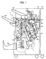
- FIG. 1 is a schematic side elevational view illustrating an image forming system including a sheet post-processing apparatus acting as a sheet processing apparatus and an image forming apparatus.
- a sheet post-processing apparatus PD is attached to a side portion of an image forming apparatus PR.
- a recording medium such as a sheet (hereafter referred to as a " sheet" ) discharged from the image forming apparatus PR is directed to the sheet post-processing apparatus PD. Then, the sheet is conveyed through a sheet conveying path A in which a sheet punching device 100 is provided.
- the sheet punching the sheet is switched to be directed to one of a sheet conveying path B leading to an upper tray 201, a sheet conveying path C leading to a shift tray 202, and a sheet conveying path D leading to a sheet stapling device F by branching pawls 15 and 16.
- the stapled sheet bundle is switched to be conveyed to one of the sheet conveying path C leading to the shift tray 202 and a sheet folding device G by a branching guide plate 54 and a movable guide 55.
- the sheet bundle subjected to folding processing in the sheet folding device G is directed to a lower tray 203 through a sheet conveying path H.
- a branching pawl 17 is disposed in the sheet conveying path D.
- the branching pawl 17 is held in a position illustrated in FIG. 1 by a low loading spring (not shown).
- a low loading spring not shown.
- the sheet stacking section E is configured such that the sheet stacked therein can be superimposed on a succeeding sheet and conveyed together. By repeating this operation, at least two sheets superimposed on each other can be conveyed together.
- an entrance sensor 301 that detects a sheet conveyed from the image forming apparatus PR is provided. Further, entrance rollers 1, the sheet punching device 100, a punch residue receiving hopper 101, conveyor rollers 2, and the branching pawls 15 and 16 are provided downstream of the entrance sensor 301 in the sheet conveying direction in the sheet conveying path A.
- the branching pawls 15 and 16 are held in positions illustrated in FIG. 1 by springs (not shown), respectively. By turning on respective solenoids (not shown), the branching pawl 15 rotates upward and the branching pawl 16 rotates downward, thereby switching a sheet to be conveyed to the sheet conveying paths B, C, and D.
- the branching pawl 15 When directing a sheet to the sheet conveying path B, the branching pawl 15 is held in a position illustrated in FIG. 1 and the solenoid is turned off.
- the respective solenoids When directing a sheet to the sheet conveying path C, the respective solenoids are turned on, thereby rotating the branching pawl 15 upward and rotating the branching pawl 16 downward.
- the branching pawl 16 When directing a sheet to the sheet conveying path D, the branching pawl 16 is held in a position illustrated in FIG. 1 and the solenoid is turned off, and the branching pawl 15 is rotated upward by turning on the solenoid.
- the sheet post-processing apparatus PD performs various types of processing on a sheet, such as punching by using the sheet punching device 100, sheet alignment and end stapling by using jogger fences 53 and an end-stapling stapler S1, sheet alignment and center stapling by using the jogger fences 53 and center-stapling staplers S2, sheet sorting by using the shift tray 202, and center folding by using a folding plate 74 and folding rollers 81.
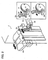
- a shift tray sheet discharging section I of the sheet post-processing apparatus PD includes shift sheet discharging rollers 6, a return roller 13, a sheet surface detecting sensor 330, the shift tray 202, a shift mechanism J illustrated in FIG. 2, and a shift tray raising and lowering mechanism K illustrated in FIG. 3.
- FIG. 2 is an enlarged perspective view of the shift mechanism J.
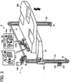
- FIG. 3 is an enlarged perspective view of the shift tray raising and lowering mechanism K.
- a reference numeral 13 indicates a return roller made of a sponge that contacts a sheet discharged by the shift sheet discharging rollers 6 and strikes a trailing edge of the sheet against an end fence 32 illustrated in FIG. 2 for alignment.
- the return roller 13 is rotated by the rotational force of the shift sheet discharging rollers 6.
- a tray raise limit switch 333 is provided in the vicinity of the return roller 13.
- the tray raise limit switch 333 becomes on and a tray raising and lowering motor 168 stops.
- the sheet surface detecting sensor 330 is provided in the vicinity of the return roller 13 to detect a sheet surface position of a sheet or a sheet bundle discharged on the shift tray 202.
- the sheet surface detecting sensor 330 includes a sheet surface detecting lever 30, a sheet surface detecting sensor (for a staple mode) 330a, and a sheet surface detecting sensor (for a non-staple mode) 330b.
- the sheet surface detecting lever 30 is configured to rotate about its shaft portion, and includes a contact portion 30a that contacts an upper surface of a trailing edge of a sheet stacked on the shift tray 202 and a sector-shaped interrupting portion 30b.
- the sheet surface detecting sensor 330a disposed at an upper side is mainly used for a stapled sheet bundle discharging control, and the sheet surface detecting sensor 330b is mainly used for a shifted sheet discharging control.
- the sheet surface detecting sensor 330a and the sheet surface detecting sensor 330b become on when the interrupting portion 30b interrupts them.
- the sheet surface detecting sensor 330a becomes off.
- the contact portion 30a of the sheet surface detecting lever 30 is further rotated upward, the sheet surface detecting sensor 330b becomes on.
- the tray raising and lowering motor 168 drives the shift tray 202 to be lowered by a predetermined distance.
- the shift tray raising and lowering mechanism K for the shift tray 202 is described.
- the shift tray 202 is raised and lowered by driving a drive shaft 21 by a drive unit L.
- a pair of timing belts 23 are provided in parallel to each other on both sides of the shift tray 202 in a direction perpendicular to a sheet discharging direction.
- Each of the timing belts 23 is spanned around the drive shaft 21 and a driven shaft 22 via timing pulleys with a tension.
- a side plate 24, which supports the shift tray 202, is fixed to the timing belts 23. In this configuration, a unit including the shift tray 202 is suspended by the timing belts 23 such that the unit including the shift tray 202 can be raised and lowered.
- the drive unit L includes the tray raising and lowering motor 168 and a worm gear 25.
- a drive force produced by the tray raising and lowering motor 168 acting as a drive source is transmitted to a last gear of a gear train fixed onto the drive shaft 21 via the worm gear 25, and thereby the shift tray 202 moves up and down.
- the tray raising and lowering motor 168 is configured to rotate in forward and reverse directions. Because a drive force transmitting system is connected to the drive shaft 21 via the worm gear 25, the shift tray 202 can be held at a constant position. Further, due to such a gear configuration, an unexpected fall accident of the shift tray 202 can be prevented.
- An interrupting plate 24a is integrally formed with the side plate 24 which supports the shift tray 202.
- a full detecting sensor 334 and a lower limit sensor 335 are disposed below the interrupting plate 24a.
- the full detecting sensor 334 detects the full load of stacked sheets, and the lower limit sensor 335 detects a lower limit position of the shift tray 202.
- the full detecting sensor 334 and lower limit sensor 335 are turned on and off by the interrupting plate 24a.
- each of the full detecting sensor 334 and the lower limit sensor 335 is formed from a photosensor.
- the full detecting sensor 334 and the lower limit sensor 335 become on when they are interrupted by the interrupting plate 24a.
- FIG. 3 an illustration of the shift sheet discharging rollers 6 is omitted.
- the shift mechanism J for the shift tray 202 includes a shift motor 169 and a shift cam 31.
- the shift tray 202 reciprocates in a direction perpendicular to a sheet discharging direction.
- a pin 31a stands on the shift cam 31 at a position away from a center of a rotation shaft of the shift cam 31.
- the other end portion of the pin 31a which is located on a side opposite from the one end portion in contact with the shift cam 31, fits loosely into an oblong hole 32b of an engaging member 32a of the end fence 32.
- the engaging member 32a is fixed on a back surface (a surface located on a side opposite from the shift tray 202) of the end fence 32, and reciprocates in the direction perpendicular to the sheet discharging direction according to a turn position of the pin 31a on the shift cam 31.
- the shift tray 202 moves in the direction perpendicular to the sheet discharging direction.
- the shift tray 202 stops at a position on a front side and at a position on a rear side relative to the sheet surface of FIG. 1.
- the stop of the shift tray 202 is controlled by detecting a cut-away portion of the shift cam 31 by a shift sensor 336 and by turning on and off the shift motor 169 based on a detection signal output from the shift sensor 336.
- Two protruded streaks 32c for guiding the shift tray 202 are provided on a front surface of the end fence 32.
- the rear end portion of the shift tray 202 fits loosely into the protruded streaks 32c such that the shift tray 202 can move up and down.
- the shift tray 202 is supported by the end fence 32 such that the shift tray 202 can move up and down and reciprocate in the direction perpendicular to the sheet discharging direction.
- the end fence 32 is configured to guide and align the trailing edge of sheets stacked on the shift tray 202.
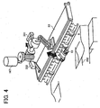
- FIG. 4 is a perspective view of the shift tray sheet discharging section I that discharges sheets to the shift tray 202.
- the shift discharging rollers 6 include a drive roller 6a and a driven roller 6b.
- the driven roller 6b is rotatably supported by a free end portion of an open/close guide plate 33.
- One end portion of the open/close guide plate 33 located on an upstream side in the sheet discharging direction is supported such that the open/close guide plate 33 can swing up and down.
- the driven roller 6b contacts the drive roller 6a by its own weight or a biasing force of the open/close guide plate 33.
- a sheet passes through a nip part between the drive roller 6a and the driven roller 6b and is discharged to the shift tray 202.
- the open/close guide plate 33 When a stapled sheet bundle is discharged, the open/close guide plate 33 is lifted and returned at predetermined timing by a guide plate open/close motor 167. Such timing is determined based on a detection signal of a shift sheet discharging sensor 303. Further, a stop position of the open/close guide plate 33 is determined based on a detection signal of a guide plate open/close sensor 331. The drive of the guide plate open/close motor 167 is controlled by on and off operations of a guide plate open/close limit switch 332.
- FIG. 5 is a top view of the sheet stapling device F seen from a direction perpendicular to a sheet stacking surface of a staple processing tray 500.
- FIG. 6 is a perspective view of the staple processing tray 500 and a drive mechanism.
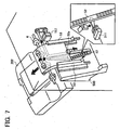
- FIG. 7 is a perspective view of a sheet discharging mechanism that discharges a stapled sheet bundle.
- the sheet directed to the sheet stapling device F by a pair of conveyor rollers 11 is stacked on the staple processing tray 500 sheet by sheet. At this time, the sheet is aligned in a lengthwise direction (i.e., a sheet conveying direction) by a hitting roller 12.
- the sheet is aligned in a widthwise direction (i.e., a direction perpendicular to a sheet conveying direction) by being jogged with the jogger fences 53.
- the end-stapling stapler S1 is driven based on a staple signal transmitted from a control device 350 (shown in FIG. 16), thereby performing end-staple processing.
- the stapled sheet bundle is conveyed to the shift sheet discharging rollers 6 by a release belt 52 on which a hook-shaped release claw 52a (shown in FIG. 7) is protrudingly provided. Subsequently, the stapled sheet bundle is discharged to the shift tray 202 set at its sheet receiving position.
- the home position of the release belt 52 is detected by a release belt home position sensor 311, and the release belt home position sensor 311 is turned on and off by the release claw 52a provided on an outer circumferential surface of the release belt 52.
- another release claw 52b is provided on the outer circumferential surface of the release belt 52 at a position opposite to the release claw 52a.
- the release claws 52a and 52b alternately convey a sheet bundle stacked on the staple processing tray 500. If necessary, the release belt 52 is rotated in a reverse direction to align the leading edge of the sheet bundle in the sheet conveying direction, which is stacked on the staple processing tray 500, by back surfaces of the release claws 52a and 52b which are in a standby condition to convey the sheet bundle.
- the release claws 52a and 52b also act as an aligning device for aligning a sheet bundle in a sheet conveying direction.
- the release belt 52 and a drive pulley 62 are disposed on a drive shaft for driving the release belt 52 by a release motor 157 at the center of the drive shaft in its axial direction which corresponds to the center of a span between the jogger fences 53. Further, release rollers 56 are disposed on the drive shaft in a symmetric state relative to the drive pulley 62. The circumferential speed of the release roller 56 is set to be higher than that of the release belt 52.
- the hitting roller 12 swings about a supporting point 12a by an operation of a solenoid 170.
- the hitting roller 12 swings to contact a surface of a sheet conveyed to the staple processing tray 500.
- the hitting roller 12 rotates to move the sheet toward an end fence 51 provided at the lower part of the staple processing tray 500, so that the trailing edge of the sheet in the sheet conveying direction is made to abut against the end fence 51 to be aligned with other sheets in the sheet conveying direction.
- the jogger fences 53 are driven to reciprocate in the sheet width direction by a jogger motor 158 via a timing belt.
- the jogger motor 158 rotates in forward and reverse directions.
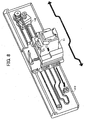
- FIG. 8 is a perspective view of the end-stapling stapler S1 and a stapler moving mechanism.
- the end-stapling stapler S1 is driven by a stapler moving motor 159 via a timing belt.
- the stapler moving motor 159 can rotate in forward and reverse directions.
- the end-stapling stapler S1 moves in a sheet width direction to staple at one portion near a corner portion of a sheet bundle.
- a stapler home position sensor 312 is disposed at one side end of a moving range of the end-stapling stapler S1 to detect a home position of the end-stapling stapler S1.
- a stapling position in the sheet width direction is controlled based on a moving amount of the end-stapling stapler S1 from the home position.
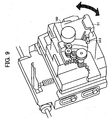
- FIG. 9 is a perspective view of a rotating mechanism for rotating the end-stapling stapler S1 of FIG. 8.
- the end-stapling stapler S1 is configured to change its stapling position such that a staple pin stapled on a sheet bundle is in parallel or slantwise relative to a side edge of the sheet bundle.
- the end-stapling stapler S1 is driven to rotate obliquely by a motor 160.
- a staple oblique position sensor 313 detects that the end-stapling stapler S1 is rotated by a predetermined oblique angle
- the motor 160 stops. Then, the end-stapling stapler S1 rotates to its original position after an oblique stapling operation is completed, and prepares for a next stapling operation.
- the center-stapling stapler S2 is disposed such that a distance between the end fence 51 and a stapling position of the center-stapling stapler S2 is greater than a distance corresponding to a half of a length of a sheet of a maximum size in a sheet conveying direction which can be center-stapled.
- the two center-stapling staplers S2 are fixed onto a stay 63 and disposed in a symmetric state relative to the center of a span between the jogger fences 53. Because the center-stapling stapler S2 has a known configuration, a detail description is omitted here.
- a sheet bundle is aligned in a direction perpendicular to a sheet conveying direction by the jogger fences 53, and the sheet bundle is aligned in the sheet conveying direction by the end fence 51 and the hitting roller 12.
- the trailing edge portion of the sheet bundle is lifted with the release claws 52a and 52b by driving the release belt 52 such that the central portion of the sheet bundle in the sheet conveying direction moves to the stapling position of the center-stapling staplers S2.
- the sheet bundle is center-stapled at this stapling position of the center-stapling staplers S2.
- the stapled sheet bundle is conveyed toward the sheet folding device G, and is subjected to center-folding processing.
- a reference character 64a indicates a front side plate
- a reference character 64b indicates a rear side plate
- a reference character 310 indicates a sheet sensor that detects a sheet on the staple processing tray 500.
- the sheet bundle subjected to the center-staple processing on the staple processing tray 500 is center-folded at the central portion of the sheet bundle.
- the center-folding processing is performed in the sheet folding device G.
- a sheet bundle shifting mechanism is provided at the most downstream side of the staple processing tray 500 in the sheet conveying direction.
- the sheet bundle shifting mechanism includes a branching guide plate 54 and a movable guide 55.
- the branching guide plate 54 swings up and down about a supporting point 54a.
- a rotatable pressing roller 57 is provided downstream of the branching guide plate 54 in the sheet conveying direction. The pressing roller 57 is pressed against the release roller 56 with a spring 58.
- the position of the branching guide plate 54 is regulated according to a contact position of the branching guide plate 54 with a cam surface 61a of a cam 61 driven to rotate by a drive motor 161.
- the movable guide 55 is swingably supported by a rotation shaft of the release roller 56.
- a link arm 60 is rotatably provided at one end of the movable guide 55 (i.e., an end portion on the side opposite from the branching guide plate 54).
- the link arm 60 is connected to the movable guide 55 via a connection part 60a.
- a shaft fixed onto the front side plate 64a (shown in FIG. 5) fits loosely into an oblong portion 60b in the link arm 60. By this fit, the swing range of the movable guide 55 is regulated.
- the link arm 60 is held at a position in FIG. 10 by being biased downward by a spring 59. When the link arm 60 is pressed by the cam surface 61b of the cam 61 rotated by the drive motor 161, the movable guide 55 rotates upward.
- a branching guide home position sensor 315 detects an interrupting portion 61c of the cam 61, thereby detecting a home position of the cam 61.
- the stop position of the cam 61 is controlled with reference to the home position of the cam 61 by counting a number of drive pulses of the drive motor 161.
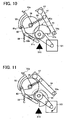
- FIG. 10 illustrates a state where the cam 61 is located at its home position.
- a guide surface 55a of the movable guide 55 has a function of guiding a sheet bundle in a path toward the shift sheet discharging rollers 6.
- FIG. 11 illustrates a state where the branching guide plate 54 is rotated about the supporting point 54a in a counter-clockwise direction (downward) by rotating the cam 61 and the pressing roller 57 press-contacts the release roller 56.
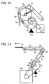
- FIG. 12 illustrates a state where the movable guide 55 is rotated in a clockwise direction (upward) by further rotating the cam 61 and a path for guiding a sheet or a sheet bundle from the sheet stapling device F to the sheet folding device G is formed by the branching guide plate 54 and the movable guide 55.
- the branching guide plate 54 and the movable guide 55 are operated by one drive motor.
- the movement timing and stop position of each of the branching guide plate 54 and the movable guide 55 may be controlled according to a sheet size and a number of stapled sheets by providing respective drive motors for the branching guide plate 54 and the movable guide 55.
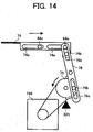
- FIGS. 13 and 14 are diagrams illustrating an operation of a moving mechanism of the folding plate 74 used in center-folding processing.
- the folding plate 74 is supported by fitting loosely two shafts 64c standing on the front and rear side plates 64a and 64b in oblong hole portions 74a. Further, a shaft portion 74b provided on the folding plate 74 fits loosely in an oblong hole portion 76b of a link arm 76. By swinging the link arm 76 about a supporting point 76a, the folding plate 74 reciprocates in the right and left directions in FIGS. 13 and 14.
- a shaft portion 75b of a folding plate drive cam 75 fits loosely in an oblong hole portion 76c of the link arm 76.
- the link arm 76 swings by rotating the folding plate drive cam 75.
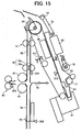
- the folding plate 74 reciprocates in a direction perpendicular to sheet conveying guide upper and lower plates 92 and 91 in FIG. 15.
- a folding plate motor 166 drives the folding plate drive cam 75 to rotate in an arrow direction in FIG. 13.
- the stop position of the folding plate drive cam 75 is determined by detecting both end portions of a semilunar interrupting portion 75a with a folding plate home position sensor 325.
- FIG. 13 illustrates a state where the folding plate 74 is located at a home position where the folding plate 74 is retracted from a sheet accommodating area in the sheet folding device G.
- the folding plate 74 moves in an arrow direction by rotating the folding plate drive cam 75 in the arrow direction, and advances toward the sheet accommodating area in the sheet folding device G.
- FIG. 14 illustrates a state where the folding plate 74 is located at a position where the folding plate 74 pushes a central portion of a sheet bundle in the sheet folding device G into a nip part between a pair of folding rollers 81.
- the folding plate 74 moves in an arrow direction by rotating the folding plate drive cam 75 in an arrow direction in FIG. 14, and retracts from the sheet accommodating area in the sheet folding device G.
- center-folding processing is performed on a stapled sheet bundle.
- the center-folding processing may also performed on a single sheet.
- a single sheet is conveyed toward the sheet folding device G without being subjected to staple processing in the sheet stapling device F.
- the center-folded single sheet is discharged to the lower tray 203.
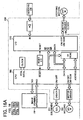
- a control device 350 is formed from a microcomputer including a central processing unit (CPU) 360 and an input/output (I/O) interface 370 in the sheet post-processing apparatus PD.
- Signals output from each of switches of a control panel (not shown) of a main body of the image forming apparatus PR and signals output from each of sensors of the sheet post-processing apparatus PD are input to the CPU 360 via the I/O interface 370.
- the sensors of the sheet post-processing apparatus PD of the present example embodiment include the entrance sensor 301 (shown in FIG. 1), an upper sheet discharging sensor 302 (shown in FIG. 1), the shift discharging sensor 303 (shown in FIG.
- a pre-stack sensor 304 shown in FIG. 1
- a staple sheet discharging sensor 305 shown in FIG. 1
- the sheet sensor 310 shown in FIGS. 1 and 5
- the release belt home position sensor 311 shown in FIGS. 1 and 7
- the stapler home position sensor 312 shown in FIG. 8
- a staple oblique position sensor 313 shown in FIG. 9
- a jogger fence home position sensor not shown
- the branching guide home position sensor 315 shown in FIGS. 10 through 12
- the CPU 360 controls the drive of solenoids such as the solenoid 170 (shown in FIG. 6), and the motors of the sheet post-processing apparatus PD based on input signals.
- the motors of the sheet post-processing apparatus PD of the present example embodiment include the tray raising and lowering motor 168 (shown in FIG. 3) for raising and lowering the shift tray 202, the guide plate open/close motor 167 (shown in FIG. 4) for opening and closing open/close guide plate 33, the shift motor 169 (shown in FIG. 2) for moving the shift tray 202, a hitting roller motor (not shown) for driving the hitting roller 12, conveyor motors for driving the conveyor rollers, discharging motors for driving the sheet discharging rollers, the release motor 157 (shown in FIG.
- the stapler moving motor 159 (shown in FIG. 8) for moving the end-stapling stapler S1
- the motor 160 (shown in FIG. 9) for obliquely rotating the end-stapling stapler S1
- the jogger motor 158 (shown in FIG. 6) for moving the jogger fences 53
- the drive motor 161 (shown in FIG. 10) for rotating the branching guide plate 54 and the movable guide 55
- a sheet bundle conveyor motor (not shown) for driving sheet bundle conveyor rollers
- a rear end fence motor 163 (shown in FIG. 26) for moving a movable rear end fence 73
- the folding plate motor 166 (shown in FIGS.
- Pulse signals of a staple conveyor motor for driving the staple sheet discharging rollers 11 are input to the CPU 360 and counted.
- the solenoid 170 and the jogger motor 158 are controlled according to the counted pulse signals.
- Each of the rear end fence motor 163 and the folding motor M is formed from a stepping motor (pulse motor), and the CPU 360 directly controls the rear end fence motor 163 and the folding motor M via a motor driver or indirectly controls the folding roller drive motor via the I/O 370 and the motor driver. Further, the sheet punching device 100 performs a punching operation based on the instruction of the CPU 360 which controls the clutch and motor for the sheet punching device 100.
- the control of the sheet post-processing apparatus PD is executed by running a program recorded in a ROM (not shown) by the CPU 360 while using a RAM (not shown) as a work area.
- the sheet post-processing apparatus PD performs the following sheet post-processing modes.
- the non-staple mode A a sheet is conveyed in the sheet conveying paths A and B to the upper tray 201 without being subjected to staple processing.
- the branching pawl 15 is rotated in a clockwise direction in FIG. 1 so that the sheet conveying path B is opened.
- the CPU 360 checks about a conveyance of a sheet by checking if the entrance sensor 301 and the upper sheet discharging sensor 302 are turned on or off. After a last sheet has been conveyed and predetermined time has elapsed, the entrance rollers 1, the conveyor rollers 2, the conveyor rollers 3, and the upper sheet discharging rollers 4 stop rotating. By these operations, all the sheets conveyed from the image forming apparatus PR to the sheet post-processing apparatus PD are discharged and stacked onto the upper tray 201 without being subjected to staple processing.
- the sheet punching device 100 is provided between the entrance rollers 1 and the conveyor rollers 2 to punch at predetermined positions of a sheet conveyed in the sheet conveying path A.
- the non-staple mode B a sheet is conveyed in the sheet conveying paths A and C to the shift tray 202 without being subjected to staple processing.
- the branching pawl 15 is rotated in a counter-clockwise direction and the branching pawl 16 is rotated in a clockwise direction in FIG. 1 so that the sheet conveying path C is opened.
- the entrance rollers 1 and the conveyor rollers 2 in the sheet conveying path A and conveyor rollers 5 and the shift sheet discharging rollers 6 in the sheet conveying path C start rotating in the sheet post-processing apparatus PD.
- the branching pawl 15 and 16 By turning on the solenoids for driving the branching pawls 15 and 16, the branching pawl 15 is rotated in a counter-clockwise direction and the branching pawl 16 is rotated in a clockwise direction.
- the CPU 360 checks about a conveyance of a sheet by checking if the entrance sensor 301 and the shift sheet discharging sensor 303 are turned on or off. After a last sheet has been conveyed and predetermined time has elapsed, the entrance rollers 1, the conveyor rollers 2, the conveyor rollers 5, and the shift sheet discharging rollers 6 stop rotating, and the solenoids for driving the branching pawls 15 and 16 are turned off. By these operations, all the sheets conveyed from the image forming apparatus PR to the sheet post-processing apparatus PD are discharged and stacked onto the shift tray 202 without being subjected to staple processing.
- the sheet punching device 100 may punch at predetermined positions of a sheet conveyed in the sheet conveying path A.
- a sheet is conveyed in the sheet conveying paths A and C to the shift tray 202, and sheets discharged to the shift tray 202 are sorted for each predetermined number of sheets by shifting the shift tray 202 in a direction perpendicular to a sheet discharging direction.
- the branching pawl 15 is rotated in a counter-clockwise direction and the branching pawl 16 is rotated in a clockwise direction in FIG. 1 so that the sheet conveying path C is opened.
- the entrance rollers 1 and the conveyor rollers 2 in the sheet conveying path A and conveyor rollers 5 and the shift sheet discharging rollers 6 in the sheet conveying path C start rotating in the sheet post-processing apparatus PD.
- the solenoids for driving the branching pawls 15 and 16 the branching pawl 15 is rotated in a counter-clockwise direction and the branching pawl 16 is rotated in a clockwise direction.
- the CPU 360 checks about a conveyance of a sheet by checking if the entrance sensor 301 and the shift sheet discharging sensor 303 are turned on or off.
- a first sheet of a set of sheets passes the shift sheet discharging sensor 303, the shift motor 169 is turned on and the shift tray 202 is shifted in the direction perpendicular to the sheet discharging direction until the shift sensor 336 detects the shift tray 202. Then, the first sheet is discharged to the shift tray 202, and the shift sheet discharging sensor 303 becomes off. If a set designated by an operator includes only one sheet, the conveyor rollers 2, the conveyor rollers 5, and the shift sheet discharging rollers 6 stop rotating, and the solenoids for driving the branching pawls 15 and 16 are turned off. If a set designated by the operator includes a plurality of sheets, a subsequent sheet is discharged to the shifted shift tray 202.
- the entrance rollers 1, the conveyor rollers 2, the conveyor rollers 5, and the shift sheet discharging rollers 6 stop rotating, and the solenoids for driving the branching pawls 15 and 16 are turned off.
- the sheet punching device 100 may punch at predetermined positions of a sheet conveyed in the sheet conveying path A.
- a sheet is conveyed in the sheet conveying paths A and D to the sheet stapling device F. Sheets are aligned and stapled in the sheet stapling device F, and a stapled sheet bundle is discharged to the shift tray 202 through the sheet conveying path C.
- the branching pawls 15 and 16 are rotated in the counter-clockwise directions, respectively, and a sheet conveying path from the sheet conveying path A to the sheet conveying path D is opened.
- the entrance rollers 1 and the conveyor rollers 2 in the sheet conveying path A, and the conveyor rollers 7, 9, 10 and the staple sheet discharging rollers 11 in the sheet conveying path D, and the hitting roller 12 in the sheet stapling device F start rotating in the sheet post-processing apparatus PD.
- the branching pawl 15 is rotated in a counter-clockwise direction.
- the end-stapling stapler S1 After the home position of the end-stapling stapler S1 is checked by detecting the end-stapling stapler S1 with the stapler home position sensor 312, the end-stapling stapler S1 is moved to a stapling position by driving the stapler moving motor 159. Further, after the home position of the release belt 52 is checked by detecting the release belt 52 with the release belt home position sensor 311, the release belt 52 is moved to its standby position by driving the release motor 157. Moreover, after the home position of the jogger fences 53 is detected with the jogger fence home position sensor (not shown), the jogger fences 53 are moved to their standby position. Further, the branching guide plate 54 and the movable guide 55 are moved to their home positions.
- the solenoid 170 is turned on for a predetermined time, and the hitting roller 12 swings to contact a surface of a sheet conveyed to the staple processing tray 500. After contacting, the hitting roller 12 rotates to move the sheet toward the end fence 51, so that the trailing edge of the sheet in the sheet conveying direction is made to abut against the end fence 51 to be aligned with other sheets in the sheet conveying direction.
- the jogger fences 53 are moved inward by a predetermined distance by driving the jogger motor 158, and thereby a sheet is aligned in a sheet width direction, that is, a direction perpendicular to a sheet conveying direction.
- the jogger fences 53 are returned to their standby position.
- the sheet conveyed onto the staple processing tray 500 is aligned in a lengthwise direction (i.e., a sheet conveying direction) and in a widthwise direction (i.e., a direction perpendicular to a sheet conveying direction).
- the jogger fences 53 move inward by a predetermined distance so as not to shift the edge surfaces of the sheet bundle. In this condition, the end-stapling stapler S1 is turned on to perform end-staple processing on the sheet bundle.
- the shift tray 202 is lowered by a predetermined distance to prepare for receiving the stapled sheet bundle.
- the shift sheet discharging rollers 6 start rotating by driving a motor (not shown), and the release belt 52 is rotated by a predetermined distance by turning on the release motor 157, thereby pushing up the stapled sheet bundle toward the sheet conveying path C.
- the shift sheet discharging rollers 6 pinch the stapled sheet bundle at a nip part between the shift sheet discharging rollers 6 and discharge it to the shift tray 202.
- the shift discharging sensor 303 is turned on and off by the passage of the stapled sheet bundle, the release belt 52 and the jogger fences 53 are moved to their standby positions.
- the shift sheet discharging rollers 6 stop rotating after a predetermined time has elapsed, and the shift tray 202 is raised to a predetermined position. This position is controlled by detecting an upper surface of an uppermost sheet of the sheet bundle stacked on the shift tray 202 with the sheet surface detecting sensor 330. These sequential operations are repeated until a job is completed.
- the end-stapling stapler S1 After the job is completed, the end-stapling stapler S1, the release belt 52, the jogger fences 53 are moved to their home positions, and the entrance rollers 1, the conveyor rollers 2, 7, 9, 10, 11, and the hitting roller 12 stop rotating. Further, the branching pawl 15 is returned to its original position by turning off the solenoid (not shown).
- the sheets conveyed from the image forming apparatus PR to the sheet post-processing apparatus PD are subjected to staple processing in the sheet stapling device F, and a stapled sheet bundle is discharged and stacked onto the shift tray 202.
- the sheet punching device 100 may punch at predetermined positions of a sheet conveyed in the sheet conveying path A.
- the jogger fences 53 move from the home positions to the standby positions.
- the standby positions are located at positions away from side edges of a sheet in a sheet width direction conveyed to the staple processing tray 500 by about 7 mm, respectively.
- each of the jogger fences 53 moves inward from the standby position by about 5 mm, and stops.
- the staple sheet discharging sensor 305 detects the passage of the trailing edge of the sheet and outputs a detection signal to the CPU 360. Then, the CPU 360 starts counting a number of pulses of a motor (not shown) for driving the conveyor rollers 11 upon receiving the detection signal from the staple sheet discharging sensor 305. After the CPU 360 counts a predetermined pulse number, the CPU 360 turns the solenoid 170 on. The hitting roller 12 swings by on/off operations of the solenoid 170. By the on operation of the solenoid 170, the hitting roller 12 rotates to move the sheet toward the end fence 51, so that the trailing edge of the sheet in the sheet conveying direction is made to abut against the end fence 51 to be aligned. Every time a sheet to be conveyed to the staple processing tray 500 passes the entrance sensor 301 or the staple sheet discharging sensor 305, a detection signal is input to the CPU 360, and thereby the CPU 360 counts a number of sheets.
- each of the jogger fences 53 is driven to move inward by about 2.6 mm by the jogger motor 158, and halts. By this operation, the side edges of the sheet in a sheet width direction are aligned. Subsequently, each of the jogger fences 53 moves outward by about 7.6 mm to the standby position, and waits for a subsequent sheet. These operations are repeated until alignment for a last sheet of a sheet bundle is completed.
- each of the jogger fences 53 moves inward by about 7 mm again and halts, and securely aligns both side edges of the sheet bundle to be subjected to staple processing.
- the end-stapling stapler S1 is driven to operate by a staple motor (not shown), and performs end-staple processing on the sheet bundle. If an operator designated two or more stapling positions, the stapler moving motor 159 is driven after staple processing at the first stapling position is completed. Then, the end-stapling stapler S1 moves along the trailing edge of the sheet bundle, and performs next staple processing at the second stapling position.
- the release belt 52 is driven by the release motor 157. Further, the shift sheet discharging rollers 6 start rotating to receive the sheet bundle lifted by the release claw 52a. At this time, the operation of the jogger fences 53 is controlled according to a sheet size and a number of stapled sheets. If a number of stapled sheets is less than a preset number or a sheet size is smaller than a preset sheet size, a trailing edge of a sheet bundle is hooked and conveyed by the release claw 52a while pressing the sheet bundle by the jogger fences 53.
- the pressing of the jogger fences 53 against the sheet bundle is released by retracting each of the jogger fences 53 by about 2 mm. If a number of stapled sheets is greater than a preset number or a sheet size is larger than a preset sheet size, each of the jogger fences 53 is retracted by about 2 mm in advance, and a sheet bundle is released. In both cases, after the sheet bundle passes through the jogger fences 53, each of the jogger fences 53 further moves outward by about 5 mm to the standby position to prepare for a subsequent sheet.
- a sheet is conveyed in the sheet conveying paths A and D to the sheet stapling device F.
- a stapled sheet bundle is subjected to center-folding processing in the sheet folding device G, and a center-folded sheet bundle is discharged to the lower tray 203 via the sheet conveying path H.
- the branching pawls 15 and 16 are rotated in the counter-clockwise directions, respectively, and a sheet conveying path from the sheet conveying path A to the sheet conveying path D is opened. Further, the branching guide plate 54 and the movable guide plate 55 go in a closed state as illustrated in FIG. 19, thereby guiding the stapled sheet bundle to the sheet folding device G.
- the entrance rollers 1 and the conveyor rollers 2 in the sheet conveying path A, the conveyor rollers 7, 9, 10, 11 in the sheet conveying path D, and the hitting roller 12 in the sheet stapling device F start rotating in the sheet post-processing apparatus PD.
- the branching pawl 15 is rotated in a counter-clockwise direction.
- the release belt 52 After detecting the home position of the release belt 52 with the release belt home position sensor 311, the release belt 52 is moved to its standby position by driving the release motor 157. Further, after detecting the home position of the jogger fences 53 with the jogger fence home position sensor, the jogger fences 53 are moved to their standby position. Moreover, the branching guide plate 54 and the movable guide 55 are moved to their home positions.
- the solenoid 170 is turned on for a predetermined time, and the hitting roller 12 swings to contact a surface of a sheet conveyed to the staple processing tray 500. After contacting, the hitting roller 12 rotates to move the sheet toward the end fence 51, so that the trailing edge of the sheet in the sheet conveying direction is made to abut against the end fence 51 to be aligned with other sheets in the sheet conveying direction.
- the jogger fences 53 are moved inward by a predetermined distance by driving the jogger motor 158, and thereby a sheet is aligned in a sheet width direction, that is, a direction perpendicular to a sheet conveying direction.
- the jogger fences 53 are returned to their standby position.
- the sheet conveyed onto the staple processing tray 500 is aligned in a lengthwise direction (i.e., a sheet conveying direction) and in a widthwise direction (i.e., a direction perpendicular to a sheet conveying direction).
- the jogger fences 53 move inward by a predetermined distance so as not to shift the edge surfaces of the sheet bundle.
- the release belt 52 is rotated by a predetermined distance by driving the release motor 157 to raise the sheet bundle to a stapling position of the center-stapling staplers S2.
- center-stapling processing is performed at a central portion of the sheet bundle by turning on the center-stapling staplers S2.
- a path for conveying the stapled sheet bundle to the sheet folding device G is formed by shifting the branching guide plate 54 and the movable guide 55 by a predetermined amount. Further, sheet conveying upper and lower rollers 71 and 72 in the sheet folding device G start rotating. After detecting the home position of the movable rear end fence 73 provided in the sheet folding device G, the rear end fence 73 is moved to its standby position.
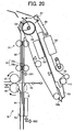
- the release belt 52 is further rotated by a predetermined distance. After the leading edge of the stapled sheet bundle is pinched between the release roller 56 and the pressing roller 57, the sheet bundle is conveyed toward the sheet folding device G. When the leading edge of the sheet bundle reaches the sheet sensor 321, the folding rollers 81 are rotated in the reverse direction, thereby conveying the sheet bundle downward without deflecting in a portion indicated by a reference character "Q" (hereafter referred to as a "portion Q") in FIG. 20. Subsequently, after a predetermined time has elapsed in which the leading edge of the sheet bundle is assumed to have passed through the portion "Q", the folding rollers 81 stop rotating.
- the sheet conveying upper and lower rollers 71 and 72 stop rotating, and pressure between the sheet conveying lower rollers 72 is released. Subsequently, a folding operation of the folding plate 74 is started, and the folding rollers 81 and sheet discharging rollers 83 start rotating.
- the folding plate 74 is moved to its home position.
- the sheet sensor 321 becomes off, the sheet conveying lower rollers 72 contact with each other with pressure, and the branching guide plate 54 and the movable guide plate 55 are moved to their home positions.
- the folding rollers 81 and the sheet discharging rollers 83 are further rotated for a predetermined time and stopped. Subsequently, the release belt 52 and the jogger fences 53 are moved to their standby positions.
- the CPU 360 checks if it is a last portion of a job. If it is not the last portion of the job, the above-described operations are similarly performed for subsequent sheets. If it is the last portion of the job, the release belt 52 and the jogger fences 53 are moved to their home positions, and the entrance rollers 1, the conveyor rollers 2, 7, 9, 10, 11, and the hitting roller 12 stop rotating.
- the branching pawl 15 is returned to its original position by turning off the solenoid (not shown).
- the sheets conveyed from the image forming apparatus PR to the sheet post-processing apparatus PD are subjected to center-staple processing in the sheet stapling device F, and a center-stapled sheet bundle is center-folded in the sheet folding device G, and a center-folded sheet bundle is discharged and stacked onto the lower tray 203.
- FIGS. 17 through 24 are diagrams illustrating operations of the sheet folding device G in the center-stapling bookbinding mode.
- FIGS. 17 through 24 illustrations and descriptions of a pressure-applying mechanism for contacting the pair of folding rollers 81 each other and a pressure-releasing mechanism for separating the folding rollers 81 from each other are omitted.
- a sheet conveyed in the sheet conveying path A is directed by the branching pawls 15 and 16 and conveyed by the conveyor rollers 7, 9, and 10 to the sheet conveying path D.
- the sheet is conveyed to the staple processing tray 500 of the sheet stapling device F by the conveyor rollers 11.
- the sheets sequentially conveyed by the conveyor rollers 11 are aligned in FIG. 17.
- a sheet bundle is conveyed by the release claw 52a toward the downstream side in the sheet conveying direction by a distance set by a sheet size.
- the center-stapling staplers S2 perform center-stapling processing on the sheet bundle at its central portion as illustrated in FIG. 18.
- the center-stapled sheet bundle is conveyed by the release claw 52a toward the downstream side by a distance set by a sheet size.
- the leading edge portion of the sheet bundle is pinched between the release roller 56 and the pressing roller 57.
- the sheet bundle is further conveyed toward the downstream side by the release claw 52a and the release rollers 56 in a sheet conveying path toward the sheet folding device G, which is formed by rotating the branching guide plate 54 and the movable guide 55 as illustrated in FIGS. 19 and 20.
- the release rollers 56 are provided on the drive shaft for driving the release belt 52 and are driven in synchronism with the release belt 52.
- the sheet bundle is conveyed to the rear end fence 73 which has been moved from its home position to a position preset according to a sheet size to guide the lower edge surface of the sheet bundle, by the sheet conveying upper and lower rollers 71 and 72.
- the release claw 52a stops at a position when the other release claw 52b, which is disposed opposite to the release claw 52a on the outer circumferential surface of the release belt 52, reaches a position adjacent to the end fence 51 illustrated in FIG. 20.
- the branching guide plate 54 and the movable guide 55 return to their home positions, and prepare for subsequent sheets.
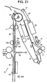
- a driven roller 72a of the sheet conveying lower rollers 72 is separated from a drive roller 72b of the rollers 72 as shown in FIG. 21, that is, the pressure at the nip part of the rollers 72 is released.
- the folding plate 74 pushes the center-stapled portion of the sheet bundle toward the nip part of the folding rollers 81 at the sheet folding position as illustrated in FIG. 22.
- the leading edge of the folding plate 74 contacts the surface of the sheet bundle at an approximately right angle.
- the folding plate 74 advances toward the nip part of the folding rollers 81 in a direction substantially perpendicular to the sheet conveying direction.
- the rotating folding rollers 81 perform center-folding processing on the sheet bundle while conveying the sheet bundle with pressure as illustrated in FIG. 23.
- the center-folded sheet bundle is discharged by the sheet discharging rollers 83 as illustrated in FIG. 24.
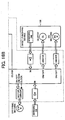
- FIG. 25 is a timing chart of a control operation of the control device 350 according to an example embodiment of the present invention.
- the timing chart shows respective drive timings of a staple motor M (not shown) for driving the center-stapling staplers S2, the drive motor 161 (shown in FIGS. 10 through 12) for driving the cam 61, the release motor 157 (shown in FIG. 5) for driving the release belt 52, a nip part open/close motor 551 for opening and closing the nip part of the sheet conveying lower rollers 72 (shown in FIG. 27), the rear end fence motor 163 (shown in FIG.
- the release motor 157 rotates in the clockwise (CW) direction, and thereby the center-stapled sheet bundle is raised by the release belt 52 and the release claw 52a.
- the drive motor 161 is driven, and thereby a sheet conveying path is formed along the periphery of the release roller 56 by the branching guide plate 54 and the movable guide 55 (i.e., the branching guide plate 54 is closed). Then, the sheet bundle is directed to the sheet conveying guide upper plate 92.
- the rear end fence motor 163 rotates in the clockwise (CW) direction to drive the rear end fence 73 to move to a standby position lower than the sheet folding position (a period "A" in FIG. 25). If a sheet size is one of A3, B4, A4, and B5, the standby position of the rear end fence 73 is set to be lower than the sheet folding position by about 10 mm. If a sheet size is 12 inch X 18 inch, the standby position of the rear end fence 73 is set to be lower than the sheet folding position by about 5 mm.
- the folding motor M rotates in the clockwise (CW) direction, and thereby the sheet conveying upper and lower rollers 71 and 72 convey the sheet bundle along the sheet conveying guide upper plate 92. Subsequently, the pressure of the pressing roller 57 against the release roller 56 is released by swinging up the branching guide plate 54 (i.e., the branching guide plate 54 is opened), and the release motor 157 and the folding motor M stop rotating. Then, the drive of each of the release motor 157 and the folding motor M is resumed.
- the folding motor M rotates for a predetermined drive pulse number.
- the drive pulse number is set according to a sheet size.
- the sheet bundle having a sheet size of A3, B4, A4, or B5 is conveyed along the sheet conveying guide upper and lower plates 92 and 91 to a position away (downward) from the sheet folding position by about 7 mm. If the sheet bundle has a sheet size of 12 inch X 18 inch, the sheet bundle is conveyed to a position away (downward) from the sheet folding position by about 2 mm.
- the nip part open/close motor 551 is rotated in the clockwise (CW) direction, and thereby a driven roller 72a of the sheet conveying lower rollers 72 is separated from a drive roller 72b of the rollers 72 as shown in FIG. 21, that is, the pressure at the nip part of the rollers 72 is released.
- the sheet bundle falls freely, and the sheet bundle abuts against the rear end fence 73 which has been moved to the standby position located downward from the sheet folding position, and is aligned.
- the rear end fence motor 163 rotates in the counter-clockwise (CCW) direction to move the rear end fence 73 from the standby position such that the sheet bundle moves to the sheet folding position of the folding plate 74.
- the folding plate 74 advances toward the sheet bundle by rotating the folding plate motor 166 in the counter-clockwise (CCW) direction for a predetermined time in a period "C" in FIG. 25. If the sheet bundle includes 2 to 5 sheets, the folding plate 74 advances to a position about 2.8 mm before the nip part of the folding rollers 81.
- the folding plate 74 advances to a position about 0.5 mm before the nip part of the folding rollers 81. Further, the folding motor M rotates in the counter-clockwise (CCW) direction to rotate the folding rollers 81 in a period "D" in FIG. 25, thereby folding the sheet bundle at the nip part of the folding rollers 81. Then, the folding plate 74 is retracted by rotating the folding plate motor 166 in the clockwise (CW) direction for a predetermined time in a period "E" in FIG. 25.
- the folding rollers 81 are repeatedly rotated in forward and reverse directions to fold the sheet bundle securely according to the number of sheets (if necessary) in a period "F" in FIG. 25. Then, the folded sheet bundle is discharged and stacked onto the lower tray 203 by the sheet discharging rollers 83 while rotating the folding motor M in the counter-clockwise (CCW) direction. At that time, the driven roller 72a of the sheet conveying lower rollers 72 is brought into contact with the drive roller 72b of the rollers 72 as shown in FIG. 24 by rotating the nip part open/close motor 551 in the clockwise (CW) direction, and the sheet conveying lower rollers 72 prepare for a conveyance of a subsequent sheet bundle.
- CCW counter-clockwise
- the folding motor M is further rotated by one counter-clockwise rotation to ensure the discharge of the sheet bundle.
- the release belt 52 is moved to its standby position by rotating the release motor 157 in the clockwise (CW) direction.
- the rear end fence 73 is returned to its standby position by rotating the rear end fence motor 163 in the clockwise (CW) direction.
- the folding plate 74 is returned to its home position by rotating the folding plate motor 166 in the clockwise (CW) direction.
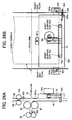
- FIG. 26A is a side view of a drive mechanism of the rear end fence 73 of the sheet folding device G.
- FIG. 26B is a front view of the drive mechanism of the rear end fence 73 of FIG. 26A.
- the rear end fence 73 has a sheet support surface for supporting and aligning the sheet bundle conveyed along the sheet conveying guide upper and lower plates 92 and 91.
- the rear end fence 73 is configured to be raised and lowered by the rear end fence motor 163, and to support the sheet bundle at two supporting points 73a and 73b.
- the rear end fence motor 163 is formed from, for example, a stepping motor (pulse motor), and the movement of the rear end fence motor 163 is controlled by setting and counting pulse numbers.
- the two supporting points 73a and 73b are provided at positions inward each by about 10 mm from positions corresponding to both edges of a B5 sized sheet placed in portrait orientation, which is a minimum sized sheet that can be subjected to center-folding processing.
- the rear end fence 73 and the rear end fence motor 163 are attached to a base 501.
- the base 501 is rotatably supported by the sheet conveying guide lower plate 91 about a rotation support point 501a.
- An adjustment screw 503 and a compression spring 501 are provided at a lower end portion of the base 501 on a right side in FIG. 26B.
- the adjustment screw 503 is connected to the base 501 with a screw portion 503a from the outer side of a front side plate via the compression spring 504.
- the compression spring 504 applies a bias force of rotating the base 501 toward a rear side plate.
- By rotating the adjustment screw 503 rightward, the base 501 is rotated toward the front side plate.
- By rotating the adjustment screw 503 leftward, the base 501 is rotated toward the rear side plate by the action of the compression spring 504.
- Base fixing portions 501b of the base 501 are fixed to the front and rear side plates with fixing screws 505, respectively, after adjusting the position of the base 501 with the adjustment screw 503 such that an angle formed between the fold line of the sheet bundle supported by the rear end fence 73 and the edge surface of the sheet bundle supported by the two supporting points 73a and 73b is 0 degree (i.e., in a parallel relation). If necessary, a cam may be used for increasing the efficiency of the adjustment operation. Alternatively, the position of the base 501 may be adjusted such that an angle ⁇ formed between the fold line of the sheet bundle supported by the rear end fence 73 and the edge surface of the sheet bundle in parallel to the sheet conveying direction is 90 degrees. The position of the base 501 is usually adjusted before shipping sheet post-processing apparatuses from a manufacturing factory.
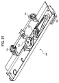
- FIG. 27 is a perspective view of a drive mechanism 550 including the nip part open/close motor 551.
- the driven roller 72a of the sheet conveying lower rollers 72 is retracted from and returned to the sheet conveying guide upper plate 92, thereby opening and closing the nip part between the drive roller 72b and the driven roller 72a of the sheet conveying lower rollers 72.
- the drive of the nip part open/close motor 551 is converted to the reciprocating motions of the driven roller 72a by a cam mechanism 553 via a reduction gear mechanism 552.
- a sheet bundle is conveyed to the sheet folding position by the rear end fence 73. Further, the skew of the sheet bundle is corrected due to a free fall to the rear end fence 73, and during a period when the sheet bundle is supported and moved to the sheet folding position. Therefore, the quality of the folded sheet bundle as a booklet can be enhanced.
- the pressure of the sheet conveying lower rollers 72 is released after the leading edge of the sheet bundle is detected by the sheet sensor 321 and reaches the position adjacent to the sheet folding position. Even if the sheet bundle is stuck in a sheet conveying path and does not reach the rear end fence 73, the rear end fence 73 is configured to move to the sheet folding position to correct the skew of the sheet bundle. Therefore, the sheet bundle can be folded properly without loss of folding quality.
- the sheet folding device G may fold a single sheet as well as a stapled sheet bundle.
- the rear end fence 73 acts as a sheet position adjusting unit that supports and moves a sheet or a sheet bundle and that adjusts the sheet or the sheet bundle to the sheet folding position.
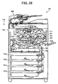
- FIG. 28 is a schematic sectional view of the image forming apparatus PR according to an example embodiment of the present invention, which is connected with the sheet post-processing apparatus PD of FIG. 1.
- the image forming apparatus PR such as a copying machine, a printer, a facsimile, or other similar image forming apparatuses, includes an auto document feeder 600, a main body 710 including an image forming device 720, and a sheet feeding unit 731.
- a monochrome image forming apparatus may be used as the image forming apparatus PR.
- the image forming device 720 includes the so-called tandem-type, four-image forming units that form images of different colors.
- Each of the image forming units includes an image carrier 701 formed from an amorphous metal, such as photoconductive amorphous silicon and amorphous selenium, and organic compounds, such as bisazo pigments, and phthalocyanine pigments. In view of environmental issues and post-processing after use, it is preferable that the image carrier 701 is formed from organic compounds.
- Each of the image forming units further includes a charging roller 721, a developing device 722, a primary transfer device 723, and a cleaning device 724, all of which are disposed around the image carrier 701.
- the image forming device 720 further includes a fixing device 727.
- the configurations and operations of the elements of each of the four image forming units are substantially the same except for the color of toner used therein.
- a corona-type charging device In place of the charging roller 721 acting as a charging device, a corona-type charging device, a roller-type charging device, a brush-type charging device, or a blade-type charging device may be employed.
- a voltage is applied to a gap between the charging roller 721 and the image carrier 701, thereby generating a corona discharge between the charging roller 721 and the image carrier 701, so that the surface of the image carrier 701 is uniformly charged.
- the image forming device 720 further includes an exposing device 711 that irradiates the surface of each of the image carriers 701 with laser light based on image data of an original document read by an image reading device (not shown) and image data transmitted from an outside device such as a personal computer (not shown). Thereby, an electrostatic latent image is formed on the surface of each of the image carriers 701.
- the developing device 722 develops the electrostatic latent image with toner, and forms a toner image on the surface of the image carrier 701.
- the toner images of different colors, which have been formed on the image carriers 701 are sequentially transferred to an intermediate transfer belt 723a, while being superimposed on one another by the respective primary transfer devices 723. Subsequently, a superimposed color image is transferred from the intermediate transfer belt 723a to a recording sheet by a secondary transfer device 725.
- the cleaning device 724 removes residual toner remaining on the image carrier 701.
- the sheet feeding unit 731 disposed below the image forming device 720 includes a plurality of sheet feeding cassettes 731a, 731b, 731c, and 731d that accommodate recording sheets therein.
- the recording sheet fed out from one or the sheet feeding cassettes 731a, 731b, 731c, and 731d is conveyed to the secondary transfer device 725 by sheet conveying rollers 732.
- the recording sheet, to which the color image is transferred from the intermediate transfer belt 723a, is conveyed to the fixing device 727 by a conveyor belt 726.
- the color image is fixed onto the recording sheet by heat and pressure'while the recording sheet passes through the fixing device 727. Subsequently, the recording sheet having a fixed color image is conveyed to the sheet post-processing apparatus PD.
- the sheet bundle mentioned in the present application text is in particular a stack of sheets.
- This stack of sheets may be at least one of the following: loose, stapled, bound together or folded. That is the sheet bundle may also be a stack of loose sheets.
Landscapes
- Physics & Mathematics (AREA)
- General Physics & Mathematics (AREA)
- Folding Of Thin Sheet-Like Materials, Special Discharging Devices, And Others (AREA)
- Pile Receivers (AREA)
Applications Claiming Priority (4)
| Application Number | Priority Date | Filing Date | Title |
|---|---|---|---|
| JP2004146701 | 2004-05-17 | ||
| JP2004146701 | 2004-05-17 | ||
| JP2005053731A JP4336322B2 (ja) | 2004-05-17 | 2005-02-28 | 用紙折り装置、用紙処理装置及び画像形成装置 |
| JP2005053731 | 2005-02-28 |
Publications (2)
| Publication Number | Publication Date |
|---|---|
| EP1598296A1 true EP1598296A1 (de) | 2005-11-23 |
| EP1598296B1 EP1598296B1 (de) | 2008-04-09 |
Family
ID=34936568
Family Applications (1)
| Application Number | Title | Priority Date | Filing Date |
|---|---|---|---|
| EP05010616A Ceased EP1598296B1 (de) | 2004-05-17 | 2005-05-17 | Bogenfalzeinrichtung |
Country Status (5)
| Country | Link |
|---|---|
| US (1) | US7427259B2 (de) |
| EP (1) | EP1598296B1 (de) |
| JP (1) | JP4336322B2 (de) |
| KR (1) | KR100614125B1 (de) |
| DE (1) | DE602005005896T2 (de) |
Families Citing this family (11)
| Publication number | Priority date | Publication date | Assignee | Title |
|---|---|---|---|---|
| JP4336322B2 (ja) | 2004-05-17 | 2009-09-30 | 株式会社リコー | 用紙折り装置、用紙処理装置及び画像形成装置 |
| US7413181B2 (en) * | 2004-11-15 | 2008-08-19 | Ricoh Company Ltd. | Method and apparatus for image forming capable of effectively performing sheet finishing operation |
| JP4950566B2 (ja) * | 2005-09-12 | 2012-06-13 | 株式会社リコー | 穿孔装置、画像形成システム |
| JP2007106597A (ja) * | 2005-09-15 | 2007-04-26 | Ricoh Co Ltd | シート揃え装置、シート処理装置及び画像形成装置 |
| US7909316B2 (en) * | 2008-02-27 | 2011-03-22 | Kabushiki Kaisha Toshiba | Sheet folding apparatus and image forming apparatus using the same |
| JP5511446B2 (ja) * | 2010-03-11 | 2014-06-04 | キヤノン株式会社 | シート処理装置及び画像形成装置 |
| JP5605119B2 (ja) * | 2010-09-21 | 2014-10-15 | 株式会社リコー | 用紙折り装置及び画像形成装置 |
| JP5967951B2 (ja) * | 2011-02-10 | 2016-08-10 | キヤノン株式会社 | シート搬送装置、これを用いた画像読取装置、及び画像形成装置 |
| JP5425294B1 (ja) * | 2012-11-21 | 2014-02-26 | 株式会社東京機械製作所 | バリアブルカットオフ折機、及びバリアブルカットオフ折機を備える印刷機 |
| JP7039941B2 (ja) * | 2017-11-10 | 2022-03-23 | 富士フイルムビジネスイノベーション株式会社 | 移動機構および画像形成装置 |
| WO2022137158A1 (en) * | 2020-12-23 | 2022-06-30 | Dandekar Sanjay Madhav | A mechanism for preventing folding of an intermediate item in a knife folder |
Citations (2)
| Publication number | Priority date | Publication date | Assignee | Title |
|---|---|---|---|---|
| US6022011A (en) * | 1996-11-01 | 2000-02-08 | Ricoh Company, Ltd. | Sheet finisher including binding, folding and stacking |
| JP2003276937A (ja) * | 2002-03-20 | 2003-10-02 | Ricoh Co Ltd | 用紙処理装置および画像形成システム |
Family Cites Families (14)
| Publication number | Priority date | Publication date | Assignee | Title |
|---|---|---|---|---|
| US4935786A (en) * | 1989-06-28 | 1990-06-19 | Digital Equipment Corporation | Method and apparatus for duplex printing |
| DE4101399A1 (de) * | 1991-01-18 | 1992-07-23 | Kodak Ag | Vorrichtung zum falten von blaettern |
| US5364332A (en) * | 1993-07-01 | 1994-11-15 | Xerox Corporation | Soft nip folder |
| US5377965A (en) * | 1993-11-08 | 1995-01-03 | Xerox Corporation | Automatic on-line signature booklets finisher for electronic printers |
| US5473419A (en) * | 1993-11-08 | 1995-12-05 | Eastman Kodak Company | Image forming apparatus having a duplex path with an inverter |
| JP3478720B2 (ja) * | 1997-12-27 | 2003-12-15 | キヤノンファインテック株式会社 | シート束折り装置及びシート処理装置 |
| JPH11322180A (ja) * | 1998-05-13 | 1999-11-24 | Canon Aptex Inc | 画像形成装置 |
| JP2001146363A (ja) | 1999-11-24 | 2001-05-29 | Konica Corp | 用紙後処理装置及び画像形成装置 |
| US6921069B2 (en) * | 2002-01-10 | 2005-07-26 | Ricoh Company, Ltd. | Sheet finisher and image forming system using the same |
| JP4021705B2 (ja) * | 2002-05-23 | 2007-12-12 | キヤノンファインテック株式会社 | シート後処理装置及びこの装置を備えた画像形成装置 |
| US6592506B1 (en) * | 2002-06-25 | 2003-07-15 | Pitney Bowes Inc. | Folder apparatus |
| JP4000962B2 (ja) * | 2002-09-05 | 2007-10-31 | コニカミノルタホールディングス株式会社 | 用紙後処理装置 |
| US6939283B2 (en) * | 2003-08-12 | 2005-09-06 | Xerox Corporation | Booklet maker with flexible gate upstream of crease rolls |
| JP4336322B2 (ja) | 2004-05-17 | 2009-09-30 | 株式会社リコー | 用紙折り装置、用紙処理装置及び画像形成装置 |
-
2005
- 2005-02-28 JP JP2005053731A patent/JP4336322B2/ja not_active Expired - Fee Related
- 2005-05-16 KR KR1020050040818A patent/KR100614125B1/ko not_active Expired - Fee Related
- 2005-05-17 DE DE602005005896T patent/DE602005005896T2/de not_active Expired - Lifetime
- 2005-05-17 US US11/130,075 patent/US7427259B2/en not_active Expired - Fee Related
- 2005-05-17 EP EP05010616A patent/EP1598296B1/de not_active Ceased
Patent Citations (2)
| Publication number | Priority date | Publication date | Assignee | Title |
|---|---|---|---|---|
| US6022011A (en) * | 1996-11-01 | 2000-02-08 | Ricoh Company, Ltd. | Sheet finisher including binding, folding and stacking |
| JP2003276937A (ja) * | 2002-03-20 | 2003-10-02 | Ricoh Co Ltd | 用紙処理装置および画像形成システム |
Non-Patent Citations (1)
| Title |
|---|
| PATENT ABSTRACTS OF JAPAN vol. 2003, no. 12 5 December 2003 (2003-12-05) * |
Also Published As
| Publication number | Publication date |
|---|---|
| KR20060047955A (ko) | 2006-05-18 |
| DE602005005896D1 (de) | 2008-05-21 |
| DE602005005896T2 (de) | 2009-06-04 |
| JP2006001738A (ja) | 2006-01-05 |
| KR100614125B1 (ko) | 2006-08-22 |
| US20050277537A1 (en) | 2005-12-15 |
| EP1598296B1 (de) | 2008-04-09 |
| JP4336322B2 (ja) | 2009-09-30 |
| US7427259B2 (en) | 2008-09-23 |
Similar Documents
| Publication | Publication Date | Title |
|---|---|---|
| US7137944B2 (en) | Sheet finisher and image forming system using the same | |
| US6957810B2 (en) | Sheet finisher with two processing trays | |
| US8162305B2 (en) | Sheet processing system, sheet-supply control method, and computer program product | |
| US6505829B2 (en) | Sheet treating apparatus and image forming apparatus having the same | |
| US7694966B2 (en) | Sheet processing apparatus and image forming apparatus | |
| US7905473B2 (en) | Sheet creaser including a cam guided pressing unit | |
| CN101456498B (zh) | 纸张压摺器、纸张运送器、纸张润饰器和图像形成设备 | |
| US7566051B2 (en) | Sheet post-processing unit and image forming apparatus | |
| US8485514B2 (en) | Sheet processing apparatus, image forming system, and sheet processing method | |
| US7336921B2 (en) | Sheet finisher with sheet folding capability and image forming system using the same | |
| US7690633B2 (en) | Sheet processing apparatus and image forming apparatus including stapling and folding mechanism | |
| US7887037B2 (en) | Sheet process apparatus | |
| EP2463219A2 (de) | Blattverarbeitungsvorrichtung, Bilderzeugungssystem und Blattverarbeitungsverfahren | |
| JP2013095583A (ja) | シート処理装置、画像形成システム及びシート処理方法 | |
| US7954800B2 (en) | Openable sheet processing device | |
| EP1598296B1 (de) | Bogenfalzeinrichtung | |
| US6283470B1 (en) | Sheet treating apparatus with aligning device and image forming apparatus having the same | |
| JP5566509B2 (ja) | シート処理装置及び画像形成装置 | |
| JP5151711B2 (ja) | シート処理装置及び画像形成装置 | |
| US6375181B1 (en) | Finisher and image forming apparatus therewith | |
| JP2004075271A (ja) | 折り装置及びその折り装置を具備する画像形成の後処理装置並びに画像形成装置 | |
| JP2004244154A (ja) | シート処理装置 | |
| JP4881679B2 (ja) | シート搬送装置、シート処理装置及び画像形成装置 |
Legal Events
| Date | Code | Title | Description |
|---|---|---|---|
| PUAI | Public reference made under article 153(3) epc to a published international application that has entered the european phase |
Free format text: ORIGINAL CODE: 0009012 |
|
| AK | Designated contracting states |
Kind code of ref document: A1 Designated state(s): AT BE BG CH CY CZ DE DK EE ES FI FR GB GR HU IE IS IT LI LT LU MC NL PL PT RO SE SI SK TR |
|
| AX | Request for extension of the european patent |
Extension state: AL BA HR LV MK YU |
|
| 17P | Request for examination filed |
Effective date: 20051227 |
|
| AKX | Designation fees paid |
Designated state(s): DE FR GB |
|
| 17Q | First examination report despatched |
Effective date: 20070605 |
|
| RTI1 | Title (correction) |
Free format text: SHEET FOLDING DEVICE |
|
| GRAP | Despatch of communication of intention to grant a patent |
Free format text: ORIGINAL CODE: EPIDOSNIGR1 |
|
| GRAS | Grant fee paid |
Free format text: ORIGINAL CODE: EPIDOSNIGR3 |
|
| GRAA | (expected) grant |
Free format text: ORIGINAL CODE: 0009210 |
|
| AK | Designated contracting states |
Kind code of ref document: B1 Designated state(s): DE FR GB |
|
| REG | Reference to a national code |
Ref country code: GB Ref legal event code: FG4D |
|
| REF | Corresponds to: |
Ref document number: 602005005896 Country of ref document: DE Date of ref document: 20080521 Kind code of ref document: P |
|
| EN | Fr: translation not filed | ||
| PLBE | No opposition filed within time limit |
Free format text: ORIGINAL CODE: 0009261 |
|
| STAA | Information on the status of an ep patent application or granted ep patent |
Free format text: STATUS: NO OPPOSITION FILED WITHIN TIME LIMIT |
|
| ET | Fr: translation filed | ||
| REG | Reference to a national code |
Ref country code: FR Ref legal event code: EERR Free format text: CORRECTION DE BOPI 09/05 - BREVETS EUROPEENS DONT LA TRADUCTION N A PAS ETE REMISE A L INPI. IL Y A LIEU DE SUPPRIMER : LA MENTION DE LA NON-REMISE. LA REMISE DE LA TRADUCTION EST PUBLIEE DANS LE PRESENT BOPI. |
|
| 26N | No opposition filed |
Effective date: 20090112 |
|
| REG | Reference to a national code |
Ref country code: FR Ref legal event code: PLFP Year of fee payment: 12 |
|
| REG | Reference to a national code |
Ref country code: FR Ref legal event code: PLFP Year of fee payment: 13 |
|
| REG | Reference to a national code |
Ref country code: FR Ref legal event code: PLFP Year of fee payment: 14 |
|
| PGFP | Annual fee paid to national office [announced via postgrant information from national office to epo] |
Ref country code: DE Payment date: 20180522 Year of fee payment: 14 |
|
| PGFP | Annual fee paid to national office [announced via postgrant information from national office to epo] |
Ref country code: FR Payment date: 20180522 Year of fee payment: 14 |
|
| PGFP | Annual fee paid to national office [announced via postgrant information from national office to epo] |
Ref country code: GB Payment date: 20180518 Year of fee payment: 14 |
|
| REG | Reference to a national code |
Ref country code: DE Ref legal event code: R119 Ref document number: 602005005896 Country of ref document: DE |
|
| GBPC | Gb: european patent ceased through non-payment of renewal fee |
Effective date: 20190517 |
|
| PG25 | Lapsed in a contracting state [announced via postgrant information from national office to epo] |
Ref country code: GB Free format text: LAPSE BECAUSE OF NON-PAYMENT OF DUE FEES Effective date: 20190517 Ref country code: DE Free format text: LAPSE BECAUSE OF NON-PAYMENT OF DUE FEES Effective date: 20191203 |
|
| PG25 | Lapsed in a contracting state [announced via postgrant information from national office to epo] |
Ref country code: FR Free format text: LAPSE BECAUSE OF NON-PAYMENT OF DUE FEES Effective date: 20190531 |