EP1598239A1 - Mikrofonbaugruppe für ein Fahrzeug - Google Patents
Mikrofonbaugruppe für ein Fahrzeug Download PDFInfo
- Publication number
- EP1598239A1 EP1598239A1 EP04025949A EP04025949A EP1598239A1 EP 1598239 A1 EP1598239 A1 EP 1598239A1 EP 04025949 A EP04025949 A EP 04025949A EP 04025949 A EP04025949 A EP 04025949A EP 1598239 A1 EP1598239 A1 EP 1598239A1
- Authority
- EP
- European Patent Office
- Prior art keywords
- panel
- housing
- microphone assembly
- microphone
- opening section
- Prior art date
- Legal status (The legal status is an assumption and is not a legal conclusion. Google has not performed a legal analysis and makes no representation as to the accuracy of the status listed.)
- Withdrawn
Links
- 238000007789 sealing Methods 0.000 claims description 4
- 229920001971 elastomer Polymers 0.000 description 5
- 238000000034 method Methods 0.000 description 4
- 230000001105 regulatory effect Effects 0.000 description 3
- 230000005489 elastic deformation Effects 0.000 description 2
- 238000003780 insertion Methods 0.000 description 2
- 230000037431 insertion Effects 0.000 description 2
- 230000000712 assembly Effects 0.000 description 1
- 238000000429 assembly Methods 0.000 description 1
- 230000001419 dependent effect Effects 0.000 description 1
- 230000000694 effects Effects 0.000 description 1
- 239000000806 elastomer Substances 0.000 description 1
- 230000002349 favourable effect Effects 0.000 description 1
Images


Classifications
-
- B—PERFORMING OPERATIONS; TRANSPORTING
- B60—VEHICLES IN GENERAL
- B60R—VEHICLES, VEHICLE FITTINGS, OR VEHICLE PARTS, NOT OTHERWISE PROVIDED FOR
- B60R11/00—Arrangements for holding or mounting articles, not otherwise provided for
- B60R11/02—Arrangements for holding or mounting articles, not otherwise provided for for radio sets, television sets, telephones, or the like; Arrangement of controls thereof
- B60R11/0247—Arrangements for holding or mounting articles, not otherwise provided for for radio sets, television sets, telephones, or the like; Arrangement of controls thereof for microphones or earphones
-
- B—PERFORMING OPERATIONS; TRANSPORTING
- B60—VEHICLES IN GENERAL
- B60R—VEHICLES, VEHICLE FITTINGS, OR VEHICLE PARTS, NOT OTHERWISE PROVIDED FOR
- B60R11/00—Arrangements for holding or mounting articles, not otherwise provided for
- B60R2011/0001—Arrangements for holding or mounting articles, not otherwise provided for characterised by position
- B60R2011/0003—Arrangements for holding or mounting articles, not otherwise provided for characterised by position inside the vehicle
- B60R2011/0028—Ceiling, e.g. roof rails
-
- B—PERFORMING OPERATIONS; TRANSPORTING
- B60—VEHICLES IN GENERAL
- B60R—VEHICLES, VEHICLE FITTINGS, OR VEHICLE PARTS, NOT OTHERWISE PROVIDED FOR
- B60R11/00—Arrangements for holding or mounting articles, not otherwise provided for
- B60R2011/0042—Arrangements for holding or mounting articles, not otherwise provided for characterised by mounting means
- B60R2011/008—Adjustable or movable supports
- B60R2011/0085—Adjustable or movable supports with adjustment by rotation in their operational position
Definitions
- the present invention relates to a microphone assembly mounted on a control module panel fitted inside a vehicle and having, for example, room lamps and various switches.
- the driver of a vehicle may sometimes make a phone call while traveling, and for such situations generally a hands free microphone and a speaker are used in a vehicle telephone from the point of view of safety.
- This hands free microphone is a component of a control module, and in many cases is fitted to a panel of the control module as a microphone assembly. In such cases, there is a problem where the microphone picks up surrounding noise such as noise outside the vehicle and vibration noise of the vehicle itself coming in from the rear of the panel.
- a microphone assembly housing 100 comprises a hard case 102 for holding a microphone, and a vibration preventing rubber cover 104 arranged so as to cover the hard case.
- An opening section of this housing 100 is arranged so as to face a sound passing section 106 formed in a panel, and a microphone 108 is fitted into this sound passing section to be able to pick up a voice inside the vehicle.
- the housing 100 reduces the extent to which surrounding noise enters as a result of passing through the housing 100 by having the vibration preventing rubber cover 104 outside.
- the vibration preventing cover 104 is elastic, and reduces surrounding noise entering through a gap potentially formed between the panel 110 and the housing 100 (vibration preventing cover 104), by preventing this gap in the first place by sealing the opening section to the panel 110.
- the housing 100 for the microphone assembly is pressed against the panel.
- a groove section 112 is provided in the housing 100, and a U-shaped section 116 of a press bracket 114 is fitted into this groove section.
- a screw fixing section 118 of the press bracket 114 is screwed to a boss section 120 provided on the panel. From the above, the position of the housing 100 with respect to the panel 110 is regulated. The housing 100 is pressed against the panel by flexing pressure of the press bracket 114.
- Patent Document 1 Japanese patent laid-open No. 2003-11736.
- the present invention is advantageous in that it provides a microphone assembly such that an opening section of a housing for the microphone assembly is sealed according to an angle of a panel surface.
- the present invention is a microphone assembly attached to a panel of a vehicle-mounted control module, provided with a housing for housing a microphone and having an opening section on a surface facing the panel, and a holding case for holding the housing so as to be capable of pivoting, and when inserted into a receptacle provided in the panel the housing pivots so as to seal the opening section of the housing to the panel.
- the microphone assembly housing pivots with respect to the holding case according to the angle of the panel surface to which the microphone assembly is attached. This is advantageous in that the opening section of the housing is sealed to the panel surface.
- the opening section of the housing is favorable for the opening section of the housing to be constructed of an elastic member. This is advantageous in that the opening section of the housing is reliably sealed to the panel surface by elastic deformation of the opening section of the housing.
- an outer case formed of a hard member held by the holding case so as to be capable of pivoting and an inner case formed of an elastic member, arranged inside the outer case, and sealing the opening section to the panel.
- This is advantageous in that it is possible to reliably arrange the elastic member at the opening section of the housing using a simple structure where the inner case is fitted into the outer case. It is also advantageous in that a gap between the opening section of the housing and the panel surface is prevented.
- the holding case and the panel it is preferable for one to be provided with engagement hooks and the other to be provided with engagement grooves, so that if the microphone assembly is inserted into a receptacle provided in the panel, the microphone assembly is fixed to the panel by engaging the engagement hooks and the engagement grooves.
- This is advantageous in that the microphone assembly is sealed in "one touch" to the panel simply by providing the receptacle at the panel side and respectively providing hook sections or groove sections for engagement for the receptacle and the microphone assembly.
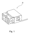
- Fig. 1 is a perspective view of a microphone assembly of this embodiment
- Fig. 2 is an assembly drawing of the microphone assembly fitted into a panel receptacle
- Fig. 3 is an exploded perspective view of a microphone assembly and fitted panel, and shows each component of the microphone assembly and a panel of a control module.
- Fig. 4A is a top view of a microphone assembly fitted to a panel
- Fig. 4B is a vertical cross section looking from the direction of arrow B.
- Fig. 5A to Fig. 5C are drawings showing operation of a housing when fitting the microphone assembly to the panel.
- FIG. 1 A perspective view of the microphone assembly of this embodiment is shown in Fig. 1.
- This microphone assembly 10 is presumed to be fitted to a panel 50 of a control module located inside a vehicle interior. Regarding components of the control module, they are generally interior lamps, various switches and a hands free microphone etc., and the microphone assembly of this embodiment is attached to a panel rear surface of the control module as a hands free microphone.
- a sound passing section 52 is provided in the panel 50, and sound inside the vehicle enters the panel rear surface.
- a receptacle 54 of the microphone assembly is also provided on the rear surface of the panel 50.
- the microphone assembly 10 of this embodiment is fitted to a panel rear surface by being inserted into this receptacle 54.
- the microphone assembly 10 is made up of a microphone or microphone element 22, a housing 24 and a holding case 26.
- the microphone 22 has a function of picking up sound, converting the sound to an electrical signal, and then outputting to a microphone amplifier that will be described later.
- the housing 24 houses the microphone 22, and has an opening section in a surface facing the panel 50. This housing 24 is held capable of pivoting with respect to the holding case 26.
- the holding case 26 has a section for holding the housing 24 and a section for housing the microphone amplifier 28, and is provided with a window so that it is possible to connect a harness 27 to a case inner section.
- the microphone amplifier 28 is connected by the harness to the microphone 22 and to the vehicle side, receives input of a voice signal from the microphone 22, amplifies this voice signal and supplies output to the vehicle side.
- the housing 24 comprises an outer case 30 made of a hard member, and an inner case 32 made of an elastic member.
- the inner case 32 is arranged so as to cover the inner surface of the outer case 30 and the edge of the opening section, and directly houses the microphone 22. It is possible to use a member such as rubber or elastomer for the elastic member of the inner case.
- the outer case 30 is formed from a hard member, and is held capable of pivoting with respect to the holding case 26. Circular projections 34 are provided on both sides surfaces of the outer case 30, while circular grooves 36 are provided on both side surfaces of the holding case 26.
- the outer case 30 is connected to the holding case 26 by fitting the projections 34 into the grooves 36 of the holding case 26. It is also possible to pivot (turn) the outer case 30 backwards and forwards with respect to the holding case 26, with the connection sites as a fulcrum.
- engagement hooks 38 are provided on the holding case 26 and engagement grooves 58 are provided in the receptacle 54 of the panel.
- guide hooks 39 are provided on the holding case 26 and guide grooves 59 are provided in the receptacle 54 of the panel.
- the direction of inserting the microphone assembly 10 into the receptacle 54 of the panel is regulated by the guide hooks 39 of the holding case and the guide grooves 59 of the receptacle. If the microphone assembly 10 is inserted, the engagement hooks 38 of the holding case 26 are fitted into the engagement grooves 58 of the receptacle and engaged. In this way, the microphone assembly 10 has its position with respect to the panel 50 regulated, and is fixed.
- the housing 24 in a process of inserting the microphone assembly 10 into the receptacle provided in the panel will be described with reference to Fig. 5A to Fig. 5C.
- part of the opening section (a part A shown in Fig. 5A) of the housing 24 comes into contact with the panel rear surface.
- the housing 24 is pivoted (Fig. 5B) in the direction shown by arrow B in Fig. 5B with respect to the holding case 26, with the contact position as a force application point, so that the opening section runs along the panel surface.
- the housing 24 has the entire opening section (positions A and B shown in Fig. 5C) sealed to the surface of the panel 50.
- the housing 24 pivots with respect to the holding case 26 according to the angle of the surface of panel 50 and the opening section is sealed.
- the opening section of the housing 24 of this embodiment can be sealed to the surface of the panel, according to the angle of the panel.
- the angle of insertion of the microphone assembly 10 the direction shown by the arrow I in Fig. 4B
- the normal angle of the surface of the panel 50 to which the opening section of the housing 24 is sealed direction shown by arrow V in Fig. 4B
- the housing of this embodiment has an "outer case” formed from a “hard member” and an “inner case” formed from an “elastic member”, and the inner case is arranged so as to cover the inner side of the outer case and the edge of the opening section, as shown in Fig. 3, will be described in the following.
- the entire opening section of the housing 24 is sealed to the rear surface of the panel 50, and the microphone assembly 10 is fixed (Fig. 5C).
- the edge of the opening section of the elastic inner case 32 is sandwiched between the edge of the opening section of the hard outer case 30 and the rear surface of the panel 50.
- the microphone assembly 10 is inserted as far as possible (Fig. 5C) .At this time, the elastic body of the housing 24 is subjected to a compressive force and is deformed. With the opening section in a compressed state, engagement hooks 38 of the holding case 26 and engagement grooves 58 of the receptacle 54 of the panel are engaged. In this way, the microphone assembly 10 seals and fixes the opening section to the panel 50.
- the microphone assembly receptacle 54 is arranged in the panel 50, by respectively providing hooks and grooves for engagement in the panel receptacle 54 and the microphone assembly 10, it is possible to easily fit the microphone assembly in "one touch".
Landscapes
- Engineering & Computer Science (AREA)
- Mechanical Engineering (AREA)
- Fittings On The Vehicle Exterior For Carrying Loads, And Devices For Holding Or Mounting Articles (AREA)
- Details Of Audible-Bandwidth Transducers (AREA)
Applications Claiming Priority (2)
| Application Number | Priority Date | Filing Date | Title |
|---|---|---|---|
| JP2004128207A JP4233483B2 (ja) | 2004-04-23 | 2004-04-23 | 車載用コントロールモジュールのパネルに取り付けるマイクアセンブリ |
| JP2004128207 | 2004-04-23 |
Publications (1)
| Publication Number | Publication Date |
|---|---|
| EP1598239A1 true EP1598239A1 (de) | 2005-11-23 |
Family
ID=34927194
Family Applications (1)
| Application Number | Title | Priority Date | Filing Date |
|---|---|---|---|
| EP04025949A Withdrawn EP1598239A1 (de) | 2004-04-23 | 2004-11-02 | Mikrofonbaugruppe für ein Fahrzeug |
Country Status (3)
| Country | Link |
|---|---|
| US (1) | US7219763B2 (de) |
| EP (1) | EP1598239A1 (de) |
| JP (1) | JP4233483B2 (de) |
Families Citing this family (5)
| Publication number | Priority date | Publication date | Assignee | Title |
|---|---|---|---|---|
| CN101600005A (zh) * | 2008-06-04 | 2009-12-09 | 深圳富泰宏精密工业有限公司 | 送话器组件及应用其的便携式电子装置 |
| TWI415439B (zh) * | 2008-06-20 | 2013-11-11 | Chi Mei Comm Systems Inc | 送話器組件及應用其之攜帶式電子裝置 |
| JP5414341B2 (ja) * | 2009-04-27 | 2014-02-12 | 小島プレス工業株式会社 | 車両用内装装置 |
| US9252534B2 (en) * | 2014-06-20 | 2016-02-02 | Schneider Electric USA, Inc. | Swing mount for terminal blocks |
| JP6088479B2 (ja) * | 2014-12-01 | 2017-03-01 | 小島プレス工業株式会社 | 車載マイク装置 |
Citations (3)
| Publication number | Priority date | Publication date | Assignee | Title |
|---|---|---|---|---|
| JP2003011736A (ja) | 2001-06-29 | 2003-01-15 | Kojima Press Co Ltd | 車載用コントロールモジュール |
| JP2003054325A (ja) * | 2001-08-10 | 2003-02-26 | Denso Corp | マイクロホンの防音構造 |
| JP2004128207A (ja) | 2002-10-02 | 2004-04-22 | Matsushita Electric Ind Co Ltd | プリント基板 |
Family Cites Families (6)
| Publication number | Priority date | Publication date | Assignee | Title |
|---|---|---|---|---|
| US4959021A (en) * | 1988-04-12 | 1990-09-25 | Byrne Norman R | Pivotable power feed connector |
| US5605145A (en) * | 1995-07-18 | 1997-02-25 | Puritan-Bennett Corporation | Microphone attenuation device for use in oxygen breathing masks |
| JP3287535B2 (ja) * | 1996-07-22 | 2002-06-04 | 矢崎総業株式会社 | コネクタの取付構造 |
| DE69829943T2 (de) * | 1997-08-05 | 2006-03-09 | Koninklijke Philips Electronics N.V. | Gerät mit eingebautem elektroakustischen wandler zur optimalen sprachwiedergabe |
| JP2000198373A (ja) * | 1998-12-28 | 2000-07-18 | Harness Syst Tech Res Ltd | インスツルメントパネル取付構造 |
| EP1392942A4 (de) * | 2001-06-01 | 2008-11-12 | Southco | Rastverriegelung mit bügelbefestigung |
-
2004
- 2004-04-23 JP JP2004128207A patent/JP4233483B2/ja not_active Expired - Lifetime
- 2004-11-02 EP EP04025949A patent/EP1598239A1/de not_active Withdrawn
- 2004-12-09 US US11/008,903 patent/US7219763B2/en not_active Expired - Lifetime
Patent Citations (3)
| Publication number | Priority date | Publication date | Assignee | Title |
|---|---|---|---|---|
| JP2003011736A (ja) | 2001-06-29 | 2003-01-15 | Kojima Press Co Ltd | 車載用コントロールモジュール |
| JP2003054325A (ja) * | 2001-08-10 | 2003-02-26 | Denso Corp | マイクロホンの防音構造 |
| JP2004128207A (ja) | 2002-10-02 | 2004-04-22 | Matsushita Electric Ind Co Ltd | プリント基板 |
Non-Patent Citations (2)
| Title |
|---|
| PATENT ABSTRACTS OF JAPAN vol. 2003, no. 05 12 May 2003 (2003-05-12) * |
| PATENT ABSTRACTS OF JAPAN vol. 2003, no. 06 3 June 2003 (2003-06-03) * |
Also Published As
| Publication number | Publication date |
|---|---|
| US20050236224A1 (en) | 2005-10-27 |
| JP2005306278A (ja) | 2005-11-04 |
| JP4233483B2 (ja) | 2009-03-04 |
| US7219763B2 (en) | 2007-05-22 |
Similar Documents
| Publication | Publication Date | Title |
|---|---|---|
| US7391863B2 (en) | Method and system for an interchangeable headset module resistant to moisture infiltration | |
| CN104541423B (zh) | 索环 | |
| US6343953B2 (en) | Structure for assembling a housing and a connector | |
| US7420125B2 (en) | Grommet assembly | |
| EP2051336B1 (de) | Verbindervorrichtung | |
| KR101364989B1 (ko) | 전자식 스로틀 밸브 제어분야에 있어서 센서 조립체의 강제끼워 맞춤 | |
| CN104620599B (zh) | 用于安装在机动车里面的话筒装置 | |
| JP5062107B2 (ja) | 電子装置の筐体構造 | |
| JP4860016B2 (ja) | フラットケーブル挿通口の蓋構造 | |
| US7219763B2 (en) | Microphone assembly fitted to vehicle-mounted control module panel, that fits well | |
| HK1048718A1 (zh) | 發射器/接收器所用的機殼、發射器/接收器及其組裝方法 | |
| JP4299203B2 (ja) | ドア用ワイヤハーネスの取付構造 | |
| US9048577B2 (en) | Lever connector with waterproofing | |
| JP4305753B2 (ja) | 防水ケース | |
| JP2003153422A (ja) | ハーネス弛み吸収装置 | |
| JP2018148398A (ja) | ハンズフリー通話補助装置およびハンズフリー通話補助システム | |
| WO2007074158A3 (de) | Steuergerätmodul, insbesondere in oder für ein kraftfahrzeug | |
| CN200966132Y (zh) | 全面板按键式麦克风 | |
| JP3419286B2 (ja) | 計器ケースの防水構造 | |
| JP4968245B2 (ja) | カバーの取り付け構造 | |
| JP2010135250A (ja) | コネクタ | |
| JP2016201738A (ja) | 無線通信装置 | |
| JP4348867B2 (ja) | ドア用グロメット | |
| JP2007256071A (ja) | パネル取付機器 | |
| JPH08191279A (ja) | 小型携帯機器の発光部の防水固定構造 |
Legal Events
| Date | Code | Title | Description |
|---|---|---|---|
| PUAI | Public reference made under article 153(3) epc to a published international application that has entered the european phase |
Free format text: ORIGINAL CODE: 0009012 |
|
| AK | Designated contracting states |
Kind code of ref document: A1 Designated state(s): AT BE BG CH CY CZ DE DK EE ES FI FR GB GR HU IE IS IT LI LU MC NL PL PT RO SE SI SK TR |
|
| AX | Request for extension of the european patent |
Extension state: AL HR LT LV MK YU |
|
| AKX | Designation fees paid | ||
| STAA | Information on the status of an ep patent application or granted ep patent |
Free format text: STATUS: THE APPLICATION IS DEEMED TO BE WITHDRAWN |
|
| 18D | Application deemed to be withdrawn |
Effective date: 20060524 |
|
| REG | Reference to a national code |
Ref country code: DE Ref legal event code: 8566 |