EP1598202A2 - Système et méthode d'approvisionnement de support pour un dispositif - Google Patents
Système et méthode d'approvisionnement de support pour un dispositif Download PDFInfo
- Publication number
- EP1598202A2 EP1598202A2 EP05252861A EP05252861A EP1598202A2 EP 1598202 A2 EP1598202 A2 EP 1598202A2 EP 05252861 A EP05252861 A EP 05252861A EP 05252861 A EP05252861 A EP 05252861A EP 1598202 A2 EP1598202 A2 EP 1598202A2
- Authority
- EP
- European Patent Office
- Prior art keywords
- tray
- pick
- media
- shaft
- printer
- Prior art date
- Legal status (The legal status is an assumption and is not a legal conclusion. Google has not performed a legal analysis and makes no representation as to the accuracy of the status listed.)
- Granted
Links
Images


Classifications
-
- B—PERFORMING OPERATIONS; TRANSPORTING
- B41—PRINTING; LINING MACHINES; TYPEWRITERS; STAMPS
- B41J—TYPEWRITERS; SELECTIVE PRINTING MECHANISMS, i.e. MECHANISMS PRINTING OTHERWISE THAN FROM A FORME; CORRECTION OF TYPOGRAPHICAL ERRORS
- B41J11/00—Devices or arrangements of selective printing mechanisms, e.g. ink-jet printers or thermal printers, for supporting or handling copy material in sheet or web form
- B41J11/48—Apparatus for condensed record, tally strip, or like work using two or more papers, or sets of papers, e.g. devices for switching over from handling of copy material in sheet form to handling of copy material in continuous form and vice versa or point-of-sale printers comprising means for printing on continuous copy material, e.g. journal for tills, and on single sheets, e.g. cheques or receipts
- B41J11/485—Means for selecting a type of copy material amongst different types of copy material in the printing apparatus
-
- B—PERFORMING OPERATIONS; TRANSPORTING
- B41—PRINTING; LINING MACHINES; TYPEWRITERS; STAMPS
- B41J—TYPEWRITERS; SELECTIVE PRINTING MECHANISMS, i.e. MECHANISMS PRINTING OTHERWISE THAN FROM A FORME; CORRECTION OF TYPOGRAPHICAL ERRORS
- B41J13/00—Devices or arrangements of selective printing mechanisms, e.g. ink-jet printers or thermal printers, specially adapted for supporting or handling copy material in short lengths, e.g. sheets
- B41J13/10—Sheet holders, retainers, movable guides, or stationary guides
- B41J13/103—Sheet holders, retainers, movable guides, or stationary guides for the sheet feeding section
-
- B—PERFORMING OPERATIONS; TRANSPORTING
- B65—CONVEYING; PACKING; STORING; HANDLING THIN OR FILAMENTARY MATERIAL
- B65H—HANDLING THIN OR FILAMENTARY MATERIAL, e.g. SHEETS, WEBS, CABLES
- B65H1/00—Supports or magazines for piles from which articles are to be separated
- B65H1/04—Supports or magazines for piles from which articles are to be separated adapted to support articles substantially horizontally, e.g. for separation from top of pile
-
- B—PERFORMING OPERATIONS; TRANSPORTING
- B65—CONVEYING; PACKING; STORING; HANDLING THIN OR FILAMENTARY MATERIAL
- B65H—HANDLING THIN OR FILAMENTARY MATERIAL, e.g. SHEETS, WEBS, CABLES
- B65H1/00—Supports or magazines for piles from which articles are to be separated
- B65H1/08—Supports or magazines for piles from which articles are to be separated with means for advancing the articles to present the articles to the separating device
- B65H1/22—Supports or magazines for piles from which articles are to be separated with means for advancing the articles to present the articles to the separating device moving in direction of plane of articles, e.g. for bodily advancement of fanned-out piles
-
- B—PERFORMING OPERATIONS; TRANSPORTING
- B65—CONVEYING; PACKING; STORING; HANDLING THIN OR FILAMENTARY MATERIAL
- B65H—HANDLING THIN OR FILAMENTARY MATERIAL, e.g. SHEETS, WEBS, CABLES
- B65H3/00—Separating articles from piles
- B65H3/02—Separating articles from piles using friction forces between articles and separator
- B65H3/06—Rollers or like rotary separators
- B65H3/0669—Driving devices therefor
-
- B—PERFORMING OPERATIONS; TRANSPORTING
- B65—CONVEYING; PACKING; STORING; HANDLING THIN OR FILAMENTARY MATERIAL
- B65H—HANDLING THIN OR FILAMENTARY MATERIAL, e.g. SHEETS, WEBS, CABLES
- B65H3/00—Separating articles from piles
- B65H3/44—Simultaneously, alternately, or selectively separating articles from two or more piles
-
- B—PERFORMING OPERATIONS; TRANSPORTING
- B65—CONVEYING; PACKING; STORING; HANDLING THIN OR FILAMENTARY MATERIAL
- B65H—HANDLING THIN OR FILAMENTARY MATERIAL, e.g. SHEETS, WEBS, CABLES
- B65H2301/00—Handling processes for sheets or webs
- B65H2301/40—Type of handling process
- B65H2301/42—Piling, depiling, handling piles
- B65H2301/422—Handling piles, sets or stacks of articles
- B65H2301/4225—Handling piles, sets or stacks of articles in or on special supports
- B65H2301/42254—Boxes; Cassettes; Containers
- B65H2301/422548—Boxes; Cassettes; Containers filling or loading process
-
- B—PERFORMING OPERATIONS; TRANSPORTING
- B65—CONVEYING; PACKING; STORING; HANDLING THIN OR FILAMENTARY MATERIAL
- B65H—HANDLING THIN OR FILAMENTARY MATERIAL, e.g. SHEETS, WEBS, CABLES
- B65H2405/00—Parts for holding the handled material
- B65H2405/30—Other features of supports for sheets
- B65H2405/33—Compartmented support
- B65H2405/332—Superposed compartments
-
- B—PERFORMING OPERATIONS; TRANSPORTING
- B65—CONVEYING; PACKING; STORING; HANDLING THIN OR FILAMENTARY MATERIAL
- B65H—HANDLING THIN OR FILAMENTARY MATERIAL, e.g. SHEETS, WEBS, CABLES
- B65H2405/00—Parts for holding the handled material
- B65H2405/30—Other features of supports for sheets
- B65H2405/35—Means for moving support
-
- B—PERFORMING OPERATIONS; TRANSPORTING
- B65—CONVEYING; PACKING; STORING; HANDLING THIN OR FILAMENTARY MATERIAL
- B65H—HANDLING THIN OR FILAMENTARY MATERIAL, e.g. SHEETS, WEBS, CABLES
- B65H2601/00—Problem to be solved or advantage achieved
- B65H2601/30—Facilitating or easing
- B65H2601/32—Facilitating or easing entities relating to handling machine
- B65H2601/322—Replenishing
-
- B—PERFORMING OPERATIONS; TRANSPORTING
- B65—CONVEYING; PACKING; STORING; HANDLING THIN OR FILAMENTARY MATERIAL
- B65H—HANDLING THIN OR FILAMENTARY MATERIAL, e.g. SHEETS, WEBS, CABLES
- B65H2701/00—Handled material; Storage means
- B65H2701/10—Handled articles or webs
- B65H2701/11—Dimensional aspect of article or web
- B65H2701/113—Size
- B65H2701/1131—Size of sheets
-
- B—PERFORMING OPERATIONS; TRANSPORTING
- B65—CONVEYING; PACKING; STORING; HANDLING THIN OR FILAMENTARY MATERIAL
- B65H—HANDLING THIN OR FILAMENTARY MATERIAL, e.g. SHEETS, WEBS, CABLES
- B65H2701/00—Handled material; Storage means
- B65H2701/10—Handled articles or webs
- B65H2701/19—Specific article or web
- B65H2701/1916—Envelopes and articles of mail
Definitions
- Media sheets are supplied to a typical printer by a supply tray (also known as an input tray), which holds a supply of the print media, such as paper, in a location that permits paper to be brought into engagement with a feed mechanism of a printer.
- the feed mechanism contacts the top sheet of the media supply and advances that sheet into the printer.
- These feed mechanisms are often referred to as "pick and feed” rollers. From the pick and feed roller, the media sheet is moved into a print zone where an image or text is printed on the sheet.
- Supply trays are normally adaptable to handle various sizes of paper.
- adjustable guides are built into the supply trays to ensure that whatever size paper is provided, it is advanced uniformly (i.e., without undesirable skewing) into the printer.
- the user is often required to remove the existing supply of paper from the tray before adding a different sized media. This slows the printing operation and requires physical interaction with the printer, which can be undesirable particularly for networked printers having users at remote locations.
- media or “print media” is intended to include cut-sheet paper of any weight, photo-grade paper (or “photo media”), transparencies, envelopes, banners, rolled media, pre-printed documents to be scanned, and equivalents as would be recognized by those skilled in the art.
- the illustrative embodiments of the invention are adapted for a printer, the invention can be adapted for many other media processing devices such as copiers, facsimile machines, scanners, and the like without departing from the scope of the present teachings.
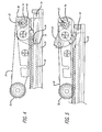
- Fig. 1a is a perspective view of a portion of a printer 10 that is adapted to use a media supply system designed in accordance with an illustrative embodiment of the present invention. Many of the printer components that are irrelevant to this description are omitted from the figure for clarity of illustration.
- the printer 10 includes a chassis or base 12 and a platen 14, which is the stationary internal structure of the printer 10 that holds the many parts of the printer 10, including a feed mechanism (the feed shaft 13 of the feed mechanism is shown in Fig. 1a) for inputting media into the printer 10 and a print mechanism 15 for forming an image on a media sheet.
- Media 16 is supplied to the feed mechanism by a novel media supply system 18.
- the media supply system 18 includes a first tray 20 for holding a first supply of media 16 and a drive mechanism (not visible in Fig. 1a) for automatically moving the tray 20 from a first position to a second position.
- the first position, or load position is located where a user can easily load media 16 into the tray 20, while the second position, or pick position, is located where the feed mechanism can pick media 16 from the tray 20 and feed it to the print mechanism 15.
- the tray 20 is shown in the load position.
- Fig. 1b is a perspective view of the printer 10, showing the tray 20 in the pick position. In this embodiment, when the tray 20 is in the pick position, it is completely concealed under the platen structure 14.
- the printer 10 may also include a second tray 22 for holding a second supply of media 23 and located where the feed mechanism can pick media from the second tray 22 when the first tray 20 is in the load position.
- the first tray 20 is adapted to hold smaller media, such as 4 x 6" photo cards
- the second tray 22 is adapted to hold larger media, such as 81 ⁇ 2 x 11" document sized paper. More detailed views of the media supply system 18 are shown in Figs. 2 and 3.
- Fig. 2a is a perspective view of a media supply system 18 designed in accordance with an illustrative embodiment of the present invention.
- Two guides 24 (left) and 26 (right) support the first tray 20. Grooves embedded in the guides 24 and 26 allow the tray 20 to slide in a direction parallel to the guides between the load and pick positions. In Fig. 2a, the tray 20 is shown in the pick position.
- the guides 24 and 26 are mounted on the chassis 12 of the printer 10 (as shown in Fig. 1).
- the system 18 may also include a mechanism for adapting the tray 20 to hold different sized media, such as a width adjustor 30 coupled to a spring 28 for biasing the media to a wall of the tray (formed, in the illustrative embodiment of Fig. 2a, by the right guide 26).
- the media supply system 18 also includes a novel input drive mechanism 34 for automatically moving the tray 20 from the load position to the pick position.
- the feed mechanism of the printer 10 typically includes a pick arm shaft 32 driven by a pick motor (not shown) that supplies rotational motion to the components of the feed mechanism.
- the input drive mechanism 34 is coupled to the pick arm shaft 32.
- the pick arm shaft 32 is normally only rotated in one direction (for example, counter-clockwise). This embodiment uses the second direction of the pick arm shaft 32 (clockwise, in the example) to drive the input drive mechanism 34.
- the feed mechanism picks media from the tray 20 (or the second tray 22).
- the pick arm shaft 32 is rotated in the second direction (“reverse pick” direction)
- the tray 20 is driven from the load position to the pick position.
- the pick arm shaft 32 When the printer 10 is instructed to print from the first supply tray 20, the pick arm shaft 32 is rotated in a reverse pick cycle until the pick motor stalls. A motor stall occurs when the tray 20 has been pulled in as far as possible, into the pick position. Then the pick arm shaft 32 cannot be rotated any further, causing a current spike in the pick motor (because the motor is forcing itself). This causes a motor stall, and the printer cuts off power to the motor. The direction of the pick shaft 32 is then reversed, and media is picked by the feed mechanism and fed to the print mechanism. The "click-to-dot" time (mechanism movement time between instructing the printer to print and when printing actually begins) is minutely affected by including the automated supply tray system 18.
- Fig. 2b is a perspective view of an input drive mechanism 34 designed in accordance with an illustrative embodiment of the present invention.
- the input drive mechanism 34 is a swing arm assembly including two gears, a small driver 36 and an arm idler 38, supported between two flat swing arm bodies, a right arm body 40 and a left arm body 42.
- the input drive mechanism 34 may also include a follower spring 48 for applying a normal force at the idler 38 and arm body 42 interface, and an arm clip 50 for supplying strength and stiffness to the swing arm assembly 34.
- the small driver 36 is adapted to engage a rack 44 embedded in the tray 20 and pull the tray 20 in from the load position to the pick position.
- the rack 44 is oriented in the direction of motion, parallel to the edge guides 24 and 26.
- the arm idler 38 is adapted to engage a pick shaft pinion 46 mounted on the pick shaft 32 and rotate the swing arm assembly 34.
- the swing arm 34 is rotated (clockwise) and lifted up, disengaging the small driver 36 from the rack 44.
- the swing arm 34 is lowered such that the small driver 36 engages the rack 44, pulling the tray 20 into the pick position.
- a separate output drive mechanism 52 (Fig. 2a) may be used to drive the tray 20 out from the pick position to the load position, after printing has been completed.
- the output drive system 52 is coupled to a different drive train in the printer 10.
- the output drive mechanism 52 is a rack and pinion drive system.
- the tray 20 includes a second rack 54 embedded in the tray 20, parallel to the first rack 44.
- the second rack or output rack 54 is shown raised slightly higher than the first input rack 44.
- the output drive mechanism 52 includes a driver gear 56 (double driver gears are shown in the example of Fig. 2a) adapted to engage the output rack 54 and drive the tray 20 out to the load position. Motion is transmitted to the driver gear 56 by an output idler gear 58, which is coupled to a drive pinion 60 by an output shaft 62.
- the drive pinion 60 is coupled to a separate drive train than the input drive system 34.
- a gear beam 64 is provided to support the output drive system 52 and the input drive system 34.
- the tray 20 is driven out until the driver gear 56 loses engagement with the output rack 54.
- a spring loaded retention system may be used to keep the tray disengaged from the output drive system 52.
- the spring loaded retention system includes a retention spring 66 mounted on the left guide 24, which biases the tray 20 in the full "out” or load position and assures the output rack 54 will not self-engage on the double driver gear 56. If the tray is reliably disengaged from the output drive system 52, an extension to the transmission can then be used to drive additional printer functionality such as CD printing, wherein the tray 20 supports a CD while a surface of the CD is printed upon.
- CD printing in some embodiments, uses both rotational directions from the pinion gear 60 that transmits motion to the output drive transmission 52.
- CD printing unlike traditional paper printing, typically uses both feed directions. Because CDs are rigid, they cannot be passed through the traditional "U" shaped paper path. If a CD is to be loaded from the front of a printer, it must be driven bi-directionally into the printer and out from the printer by the feed mechanism. The retention system 66 provides that both directions of rotations will be available for CD printing (or other printer functions) until the automated tray 20 is activated (i.e. pulled into the pick position).
- Fig. 3a is an isometric view of an illustrative power transmission arrangement 80 for providing power to the media supply system 18 of Figs. 2a and 2b
- Fig. 3b is a side view of the illustrative power transmission arrangement 80.
- the printer 10 includes two motors 82 and 84.
- the first motor 82 drives a first input gear 86, causing it to rotate.
- the second motor 84 drives a second input gear 88.
- the first input gear 86 engages a gear 87
- the second input gear 88 engages a gear 89.
- the gears 87 and 89 are each adapted to engage a gear in one of a plurality of gear trains 90, 92, 94, and 96, each gear train including two gears (90A and 90B, 92A and 92B, 94A and 94B, and 96A and 96B, respectively).
- the gear 87 is positioned to engage gear 90A, 92A, 94A, or 96A
- gear 89 is positioned to engage gear 90B, 92B, 94B, or 96B, depending on the position of a swing arm 99.
- Each of the gears in the gear trains is coupled to a different part of the printer.
- gear 90A may be coupled to the pick shaft 32 (of Fig. 2a) and gear 92A may be coupled to the output shaft 62.
- a carriage shift may be used to shift from one gear train to another.
- the carriage (not shown) is adapted to engage a leash 98, allowing the swing arm 99 to rotate and change position, and coupling the gears 87 and 89 to a selected gear train.
- the swing arm 99 is shown in a "neutral" position, such that the input gears 86 and 88 are not coupled to any of the gear trains.
- the power transmission system 80 is shifted from neutral to gear train 90.
- Motor 82 is therefore coupled to the pick shaft 32.
- the motor 82 is driven in a first direction, causing the pick shaft 32 to rotate in the reverse pick direction, pulling the tray 20 into the pick position (as described above).
- the motor 82 is then reversed, causing the pick shaft 32 to rotate in the pick direction, feeding paper into the printer. Reversing the motor 82 takes a relatively small amount of time.
- the transmission system 80 is shifted from gear train 90 to gear train 92, coupling motor 82 to the output shaft 62. This shifting of gears typically takes a much longer time than reversing a motor; however, additional time after printing (unlike before printing) is usually deemed acceptable.
- Figs. 4-6 illustrate the operation of the input and output drive mechanisms 34 and 52.
- the pick direction is counter-clockwise and the reverse pick direction is clockwise.
- the feed mechanism of the printer 10 includes a pick arm 70 coupled to the pick shaft 32.
- the pick arm 70 includes one or more pick and feed rollers 72 for picking media 16 from the input tray 20 and feeding it to the print mechanism of the printer 10.
- Fig. 4 is a side view showing the locations of the pick arm 70 and the swing arm assembly 34 during the movement of the automated input tray 20 from the load position to the pick position.
- the pick arm 70 is fully lifted off the media stack 16 while the input drive swing arm 34 engages on the input rack 44 of the tray 20 and pulls the tray 20 until the pick position is reached. This position is achieved by rotating the pick arm shaft 32 in the reverse pick direction (counter-clockwise with respect to the figure).
- a follower spring (not shown) may be used to create friction between a driving gear 74 (mounted on the pick shaft 32, that drives the pick arm gears) and the pick arm body 70.
- Fig. 5 is a side view showing the locations of the pick arm 70 and the swing arm assembly 34 during the media pick algorithm.
- Fig. 6 is a side view showing the locations of the pick arm 70 and the swing arm assembly 34 during the movement of the automated input tray 20 from the pick position to the load position.
- the pick arm shaft 32 is rotated in the reverse pick direction a slight amount. This will lift the pick arm 70 off any remaining media 16 and rotate the swing arm 34 in the counter-clockwise direction (yet not enough to engage the input rack 44 on the tray 20).
- the printer 10 then shifts to the output drive transmission 52 and the double driver 56 will push the tray 20 out to the load position. Now media 16 can be reloaded, and the cycle repeated.
- the pick arm 70 when the tray 20 is out in the load position, the pick arm 70 can be lowered to pick media from a second media supply being held in a second input tray 22, which is located beneath the first tray 20 (as shown in Fig. 1).
- Fig. 7 is a flow diagram of the operation of the automated input tray 20, according to an example embodiment.
- the automated tray 20 is adapted to hold 4 x 6" photo media
- the second input tray 22 is adapted to hold document sized paper.
- the sizes and types of these media may, of course, vary.
- photo media may be employed, while in other embodiments a variety of other suitable media are employed.
- a print cycle begins at Step 102 when a user clicks on "print photo” in the printer driver. This starts an input cycle 104.
- An input cycle 104 includes the following steps.
- Step 106 shift the transmission from neutral to position 1 (coupling the motors 82 and 84 to the gear train 90 to drive the pick shaft 32, as shown in Fig. 3b).
- Step 108 rotate the pick shaft 32 in the reverse pick direction for a predetermined distance, pulling the tray 20 into the pick position.
- Step 110 determine whether a motor stall was detected. If no, then at Step 112, rotate the pick shaft 32 slowly in the reverse pick direction until a stall is detected, indicating that the tray 20 is fully in.
- Step 114 determine whether the printer 10 is supposed to be printing or hiding the tray 20 (both of which start an input cycle). If printing, then enter the pick sequence at Step 122. If hiding, then enter a standby mode 116 with the tray 20 in the pick position. This enables compact storage 118 of the tray 20. While the automated tray 20 is in the pick position, printing using media from the second tray 22 cannot occur (the automated tray 20 must first be ejected). If printing from the first media supply (photo printing) is desired while the automated tray 20 is in the pick position, the printer 10 can then go straight to the pick sequence at Step 122.
- Step 124 determine whether media was successfully picked. If yes, at Step 126 prepare for the next print job. If the next print job is another photo (same media supply), then go to Step 122 to pick another media sheet. If the next print job is a full sized document (second media supply from the second input tray 22) or the print jobs are completed, then go to the output cycle 132.
- Step 124 determines whether the automated tray 20 is out of paper (Step 128). If yes, then go to the output cycle 132. If no, then solve the problem that occurred (Step 130).
- the output cycle 132 begins at Step 134, rotating the pick shaft 32 in the reverse pick direction by a small amount to lift the pick arm 70 off of the automated tray 20.
- Step 136 shift the transmission from position 1 (pick shaft 32) to position 2 (coupling the motors 82 and 84 to the gear train 92 to drive the output shaft 62, as shown in Fig. 3b).
- Step 138 rotate the output shaft 62 by a predetermined distance to drive the tray 20 out to the load position.
- Step 140 determine whether a tray lock is desired. If no, then continue to Step 146.
- Step 142 shift the transmission from position 2 to position 1 and, at Step 144, rotate the pick shaft 32 in the pick direction a small amount, lowering the swing arm assembly 34 to engage and lock the tray 20.
- the tray 20 is now in the load position (Step 146).
- Step 148 determine if continued printing with the first media supply (photo media) is desired. If yes, at Step 150, a user can load more media into the automated tray 20. Printing can then continue at Step 102, when "print photo" is clicked in the driver. If no, at Step 152, determine whether the automated tray 20 should be hidden (for storage). If yes, then go to the input cycle 104. If no, then enter a standby mode 154 with the automated tray 20 in the load position. From this position, CD printing 156 is possible, and a user can load more media into the automated tray 20 (Step 150).
- the automated tray of the present invention is a software driven media tray that automatically moves media from a load position (where media can be loaded by a user) to a pick position (where transport of the media through the printer mechanism begins). Once the tray is empty, or photo printing is finished, the driver automatically outputs the tray back into the load position.
- the only user interface is the physical loading of the media into the tray and then clicking "print photo" in the device driver. In some embodiments, the user should only have to touch the media and not the printer during loading.
- the media in the automated tray is oriented in the "landscape" direction, providing a significant increase in print speed (as compared to orientation in the "portrait” direction) and also allowing for a compact printer design with foldable trays.
- the driver settings can be adapted to automatically change to a desired print mode (such as optimized for 4 x 6" borderless photo printing) whenever the automated tray is instructed to retract once "print photo" is clicked.
- the automated tray is dedicated to one type of media, such as 4 x 6" photo media.
- the driver settings can therefore be set to that specific size and type of media. The user would always have the correct print mode settings since, in this example, all 4 x 6" photo printing would occur in this tray. Dedicating a tray to 4 x 6" photo media would not only automate the loading of the media, but also the driver settings to support this specific media.
- An automated tray designed in accordance with the teachings of the present invention could also support wireless printing of photos and normal media (as long as photo media was already loaded in the automated tray). With a supply of photo media in the automated tray, a user could wirelessly order a normal (full-size fast mode) print job and then consecutively a best mode borderless photo print with zero physical interaction.
Landscapes
- Engineering & Computer Science (AREA)
- Mechanical Engineering (AREA)
- Sheets, Magazines, And Separation Thereof (AREA)
- Handling Of Cut Paper (AREA)
- Manual Feeding Of Sheets (AREA)
Applications Claiming Priority (2)
| Application Number | Priority Date | Filing Date | Title |
|---|---|---|---|
| US850089 | 1992-03-12 | ||
| US10/850,089 US7398969B2 (en) | 2004-05-20 | 2004-05-20 | System and method for supplying media to a device |
Publications (3)
| Publication Number | Publication Date |
|---|---|
| EP1598202A2 true EP1598202A2 (fr) | 2005-11-23 |
| EP1598202A3 EP1598202A3 (fr) | 2006-10-11 |
| EP1598202B1 EP1598202B1 (fr) | 2009-07-08 |
Family
ID=34941224
Family Applications (1)
| Application Number | Title | Priority Date | Filing Date |
|---|---|---|---|
| EP05252861A Expired - Fee Related EP1598202B1 (fr) | 2004-05-20 | 2005-05-10 | Système et méthode d'approvisionnement de support pour un dispositif |
Country Status (5)
| Country | Link |
|---|---|
| US (1) | US7398969B2 (fr) |
| EP (1) | EP1598202B1 (fr) |
| JP (1) | JP3884755B2 (fr) |
| SG (1) | SG117538A1 (fr) |
| TW (1) | TW200540019A (fr) |
Cited By (2)
| Publication number | Priority date | Publication date | Assignee | Title |
|---|---|---|---|---|
| WO2006130349A2 (fr) * | 2005-06-01 | 2006-12-07 | Hewlett-Packard Development Company, L.P. | Plateau de support multimedia automatique, verrouillable a blocage/deblocage |
| CN104339887A (zh) * | 2013-08-07 | 2015-02-11 | 兄弟工业株式会社 | 片材托盘 |
Families Citing this family (10)
| Publication number | Priority date | Publication date | Assignee | Title |
|---|---|---|---|---|
| DE102004002646A1 (de) * | 2004-01-17 | 2005-08-04 | Nexpress Solutions Llc | Vorrichtung zur Ausrichtung eines Stapels von Bögen |
| US8259367B2 (en) * | 2008-03-11 | 2012-09-04 | Hewlett-Packard Development Company, L.P. | In tray media sensing |
| JP5354965B2 (ja) * | 2008-06-13 | 2013-11-27 | キヤノン株式会社 | 記録装置 |
| JP5288944B2 (ja) * | 2008-08-21 | 2013-09-11 | キヤノン株式会社 | 記録装置 |
| JP6094081B2 (ja) * | 2012-07-23 | 2017-03-15 | セイコーエプソン株式会社 | 記録装置 |
| JP6197324B2 (ja) * | 2013-03-27 | 2017-09-20 | セイコーエプソン株式会社 | 記録装置 |
| JP6260249B2 (ja) | 2013-12-13 | 2018-01-17 | セイコーエプソン株式会社 | 印刷装置 |
| EP3337741B1 (fr) * | 2015-09-30 | 2020-05-13 | Hewlett-Packard Development Company, L.P. | Ensemble plateau de support multimédia |
| WO2018048413A1 (fr) | 2016-09-09 | 2018-03-15 | Hewlett-Packard Development Company, L.P. | Ensemble circuit imprimé de plateau d'imprimante |
| US10315439B2 (en) | 2017-07-15 | 2019-06-11 | Hewlett-Packard Development Company, L.P. | Transmissions with retention noses |
Citations (4)
| Publication number | Priority date | Publication date | Assignee | Title |
|---|---|---|---|---|
| US4023792A (en) * | 1971-12-08 | 1977-05-17 | Xerox Corporation | Sheet feeding apparatus |
| JPH0753067A (ja) * | 1993-08-11 | 1995-02-28 | Ricoh Co Ltd | 給紙装置 |
| US6056285A (en) * | 1996-05-09 | 2000-05-02 | Fuji Xerox Co., Ltd. | Sheet material feeding device and image forming device |
| JP2002362763A (ja) * | 2001-06-11 | 2002-12-18 | Nec Eng Ltd | 給紙カセット排出/収納機構 |
Family Cites Families (10)
| Publication number | Priority date | Publication date | Assignee | Title |
|---|---|---|---|---|
| JPH0544357Y2 (fr) * | 1987-10-23 | 1993-11-10 | ||
| US5005817A (en) * | 1989-06-02 | 1991-04-09 | Compaq Computer Corporation | Sheet feeding mechanism and method for an electrophotographic printer |
| US5044620A (en) * | 1989-06-02 | 1991-09-03 | Compaq Computer Corporation | Apparatus for controlling the movement of trays of paper within an electrophotographic printer |
| US5215303A (en) * | 1990-07-06 | 1993-06-01 | Konica Corporation | Sheet alignment device for a copying apparatus having an intermediate standby position |
| JPH05286591A (ja) * | 1992-04-15 | 1993-11-02 | Konica Corp | 画像形成装置 |
| JPH05286592A (ja) * | 1992-04-15 | 1993-11-02 | Konica Corp | 画像形成装置 |
| JPH05294473A (ja) * | 1992-04-17 | 1993-11-09 | Konica Corp | 画像形成装置 |
| JP3332893B2 (ja) | 1998-10-07 | 2002-10-07 | キヤノン株式会社 | シート材給送装置及び画像形成装置 |
| US6619656B2 (en) * | 2002-01-25 | 2003-09-16 | Hewlett-Packard Company, L.P. | Paper tray with automatically adjusting guides |
| JP2003285945A (ja) | 2002-03-27 | 2003-10-07 | Sekonic Corp | 自動給紙装置の制御機構 |
-
2004
- 2004-05-20 US US10/850,089 patent/US7398969B2/en not_active Expired - Fee Related
-
2005
- 2005-04-20 TW TW094112555A patent/TW200540019A/zh unknown
- 2005-04-20 SG SG200502377A patent/SG117538A1/en unknown
- 2005-05-10 EP EP05252861A patent/EP1598202B1/fr not_active Expired - Fee Related
- 2005-05-18 JP JP2005145554A patent/JP3884755B2/ja not_active Expired - Fee Related
Patent Citations (4)
| Publication number | Priority date | Publication date | Assignee | Title |
|---|---|---|---|---|
| US4023792A (en) * | 1971-12-08 | 1977-05-17 | Xerox Corporation | Sheet feeding apparatus |
| JPH0753067A (ja) * | 1993-08-11 | 1995-02-28 | Ricoh Co Ltd | 給紙装置 |
| US6056285A (en) * | 1996-05-09 | 2000-05-02 | Fuji Xerox Co., Ltd. | Sheet material feeding device and image forming device |
| JP2002362763A (ja) * | 2001-06-11 | 2002-12-18 | Nec Eng Ltd | 給紙カセット排出/収納機構 |
Non-Patent Citations (2)
| Title |
|---|
| PATENT ABSTRACTS OF JAPAN vol. 1995, no. 05, 30 June 1995 (1995-06-30) -& JP 07 053067 A (RICOH CO LTD), 28 February 1995 (1995-02-28) * |
| PATENT ABSTRACTS OF JAPAN vol. 2003, no. 04, 2 April 2003 (2003-04-02) -& JP 2002 362763 A (NEC ENG LTD), 18 December 2002 (2002-12-18) * |
Cited By (5)
| Publication number | Priority date | Publication date | Assignee | Title |
|---|---|---|---|---|
| WO2006130349A2 (fr) * | 2005-06-01 | 2006-12-07 | Hewlett-Packard Development Company, L.P. | Plateau de support multimedia automatique, verrouillable a blocage/deblocage |
| WO2006130349A3 (fr) * | 2005-06-01 | 2007-02-01 | Hewlett Packard Development Co | Plateau de support multimedia automatique, verrouillable a blocage/deblocage |
| US7540491B2 (en) | 2005-06-01 | 2009-06-02 | Hewlett-Packard Development Company, L.P. | Automatic, lockable, engageable and disengageable media tray |
| CN104339887A (zh) * | 2013-08-07 | 2015-02-11 | 兄弟工业株式会社 | 片材托盘 |
| CN104339887B (zh) * | 2013-08-07 | 2018-10-12 | 兄弟工业株式会社 | 片材托盘 |
Also Published As
| Publication number | Publication date |
|---|---|
| EP1598202B1 (fr) | 2009-07-08 |
| EP1598202A3 (fr) | 2006-10-11 |
| TW200540019A (en) | 2005-12-16 |
| JP2005330105A (ja) | 2005-12-02 |
| US20050258586A1 (en) | 2005-11-24 |
| SG117538A1 (en) | 2005-12-29 |
| US7398969B2 (en) | 2008-07-15 |
| JP3884755B2 (ja) | 2007-02-21 |
Similar Documents
| Publication | Publication Date | Title |
|---|---|---|
| EP1598202B1 (fr) | Système et méthode d'approvisionnement de support pour un dispositif | |
| US8220795B2 (en) | Printer and dual trays for image receiver media sheets | |
| JP4640334B2 (ja) | シート搬送装置 | |
| US7594652B2 (en) | Separation system | |
| US7651082B2 (en) | Media stack stop | |
| US7455285B2 (en) | Media handling accessory and method | |
| US7731184B2 (en) | Duplexer | |
| JP3819628B2 (ja) | 文書支持および持ち上げ機構を備える自動文書フィーダ装置 | |
| US20060175747A1 (en) | Media handling system | |
| EP1369367A2 (fr) | Correction de désalignement pour un méchanisme d'alimentation de supports d'impression | |
| US7694952B2 (en) | Print media bin | |
| JP4488032B2 (ja) | 画像記録装置 | |
| CN112606565A (zh) | 记录装置 | |
| JP2005212906A (ja) | 記録装置 | |
| US6454476B1 (en) | Apparatus and method for picking and feeding print media sheets | |
| US7654513B2 (en) | Feed assist assembly | |
| JP2009208862A (ja) | 用紙収容装置および画像記録装置 | |
| JP2008247593A (ja) | シート供給装置、及びこのシート供給装置を備えた画像記録装置 | |
| JP4529916B2 (ja) | 給送装置およびエッジガイド | |
| JP5505343B2 (ja) | 搬送装置 | |
| JP2023174538A (ja) | 画像形成装置 | |
| AU6070598A (en) | Paper-feeding apparatus | |
| JP2007261762A (ja) | 記録装置およびその給紙機構 | |
| JPH06144610A (ja) | 給紙装置 |
Legal Events
| Date | Code | Title | Description |
|---|---|---|---|
| PUAI | Public reference made under article 153(3) epc to a published international application that has entered the european phase |
Free format text: ORIGINAL CODE: 0009012 |
|
| AK | Designated contracting states |
Kind code of ref document: A2 Designated state(s): AT BE BG CH CY CZ DE DK EE ES FI FR GB GR HU IE IS IT LI LT LU MC NL PL PT RO SE SI SK TR |
|
| AX | Request for extension of the european patent |
Extension state: AL BA HR LV MK YU |
|
| PUAL | Search report despatched |
Free format text: ORIGINAL CODE: 0009013 |
|
| AK | Designated contracting states |
Kind code of ref document: A3 Designated state(s): AT BE BG CH CY CZ DE DK EE ES FI FR GB GR HU IE IS IT LI LT LU MC NL PL PT RO SE SI SK TR |
|
| AX | Request for extension of the european patent |
Extension state: AL BA HR LV MK YU |
|
| 17P | Request for examination filed |
Effective date: 20070321 |
|
| AKX | Designation fees paid |
Designated state(s): GB NL |
|
| 17Q | First examination report despatched |
Effective date: 20070611 |
|
| REG | Reference to a national code |
Ref country code: DE Ref legal event code: 8566 |
|
| GRAP | Despatch of communication of intention to grant a patent |
Free format text: ORIGINAL CODE: EPIDOSNIGR1 |
|
| GRAS | Grant fee paid |
Free format text: ORIGINAL CODE: EPIDOSNIGR3 |
|
| GRAA | (expected) grant |
Free format text: ORIGINAL CODE: 0009210 |
|
| AK | Designated contracting states |
Kind code of ref document: B1 Designated state(s): GB NL |
|
| REG | Reference to a national code |
Ref country code: GB Ref legal event code: FG4D |
|
| PLBE | No opposition filed within time limit |
Free format text: ORIGINAL CODE: 0009261 |
|
| STAA | Information on the status of an ep patent application or granted ep patent |
Free format text: STATUS: NO OPPOSITION FILED WITHIN TIME LIMIT |
|
| 26N | No opposition filed |
Effective date: 20100409 |
|
| REG | Reference to a national code |
Ref country code: NL Ref legal event code: V1 Effective date: 20101201 |
|
| PG25 | Lapsed in a contracting state [announced via postgrant information from national office to epo] |
Ref country code: NL Free format text: LAPSE BECAUSE OF NON-PAYMENT OF DUE FEES Effective date: 20101201 |
|
| PGFP | Annual fee paid to national office [announced via postgrant information from national office to epo] |
Ref country code: GB Payment date: 20130424 Year of fee payment: 9 |
|
| GBPC | Gb: european patent ceased through non-payment of renewal fee |
Effective date: 20140510 |
|
| PG25 | Lapsed in a contracting state [announced via postgrant information from national office to epo] |
Ref country code: GB Free format text: LAPSE BECAUSE OF NON-PAYMENT OF DUE FEES Effective date: 20140510 |