EP1596329B1 - Procédé pour estimer une information de position de repère d'image et dispositif pour le traitement d'informations - Google Patents
Procédé pour estimer une information de position de repère d'image et dispositif pour le traitement d'informations Download PDFInfo
- Publication number
- EP1596329B1 EP1596329B1 EP05252877A EP05252877A EP1596329B1 EP 1596329 B1 EP1596329 B1 EP 1596329B1 EP 05252877 A EP05252877 A EP 05252877A EP 05252877 A EP05252877 A EP 05252877A EP 1596329 B1 EP1596329 B1 EP 1596329B1
- Authority
- EP
- European Patent Office
- Prior art keywords
- markers
- marker
- constraint condition
- orientation
- plane
- Prior art date
- Legal status (The legal status is an assumption and is not a legal conclusion. Google has not performed a legal analysis and makes no representation as to the accuracy of the status listed.)
- Not-in-force
Links
Images


Classifications
-
- G—PHYSICS
- G06—COMPUTING; CALCULATING OR COUNTING
- G06T—IMAGE DATA PROCESSING OR GENERATION, IN GENERAL
- G06T7/00—Image analysis
- G06T7/70—Determining position or orientation of objects or cameras
- G06T7/73—Determining position or orientation of objects or cameras using feature-based methods
Definitions
- the present invention relates to a method and device for estimating the placement information of a marker disposed within a 3-D space.
- MR Magnetic Reality
- AR Augmented Reality
- virtual space over real space has particularly attracted attention.
- An image display device on which the AR technology displays an image is realized by a video see-through method which displays a synthesized image obtained by superimposing a computer-generated image concerned with virtual space (a virtual object, character information, or the like, drawn with computer graphics) rendered according to the position and orientation of a later-described imaging device over an image of real space photographed using an imaging device such as a video camera, or by an optical see-through method which displays an image of virtual space rendered according to an observer's viewing position and orientation on an optical-see-through-type display mounted on the observer's head.
- a video see-through method which displays a synthesized image obtained by superimposing a computer-generated image concerned with virtual space (a virtual object, character information, or the like, drawn with computer graphics) rendered according to the position and orientation of a later-described imaging device over an image of real space photographed using an imaging device such as a video camera, or by an optical see-through method which displays an image of virtual space rendered according to an observer's viewing position and orientation on an optical-
- the registration problem in the AR technology corresponds to a problem of obtaining the position and orientation of an imaging device in a scene (i.e., in the reference coordinate system) in the case of the video see-through method.
- the registration problem corresponds to a problem for obtaining the position and orientation of an observer or a display device in the scene.
- a commonly-employed method for solving the former problem is to dispose artificial markers or make natural characteristic points markers in the scene, based on the correspondence between the projected positions of the markers within an image photographed by an imaging device and the positions in the reference coordinate system of the markers, so as to obtain the position and orientation of the imaging device in the reference coordinate system.
- a commonly-employed method for solving the latter problem is to mount the imaging device on a target to be measured (e.g., an observer's head or display), with the position and orientation of the imaging device being obtained in the same way as with the former method, and the position and orientation of the target to be measured is obtained based thereupon.
- the example in Fig. 1 illustrates a situation in which four markers Q 1 , Q 2 , Q 3 , and Q 4 are disposed. Of these, three markers Q 1 , Q 3 , and Q 4 are inside the field of view of the imaging device 130 and one marker Q 2 is outside the field of view of the imaging device 130.
- the markers Q k can be any shape, such as a circular marker having a different color from other markers, or the like, as long as the projected position of a marker within a photographed image can be detected, and also the marker can be identified. For example, natural characteristic points within 3-D space may be employed, and such points may be detected within a photographed image using template matching.
- An image output from the imaging device 130 is input to the position-orientation measuring device 100.
- the marker detecting unit 110 inputs an image by the imaging device 130, and detects the image coordinates of the markers Q k photographed on the image.
- the marker detecting unit 110 detects a region corresponding to each marker color from on the input image, and takes the barycentric position as the detected coordinates of the marker.
- the position-orientation calculating unit 120 calculates the position and orientation of the imaging device 130 based on the correlation between the image coordinates u Mkn of each detected marker Q kn and the position in the reference coordinate system of the marker Q kn , which is held as known information beforehand.
- a method for calculating the position and orientation of an imaging device based on a pair of the 3-D coordinates of a marker and image coordinates has been proposed in the field of photogrammetry as of old (for example, see R. M. Haralick, C. Lee, K. Ottenberg, and M. Nolle: "Review and analysis of solutions of the three point perspective pose estimation problem", Int'l. J. Computer Vision, vol. 13, no. 3, pp. 331-356, 1994 and M. A.
- a calculation method of the position and orientation of an imaging device using combination of square markers and point markers has been proposed, as disclosed in H. Kato, M. Billinghurst, I. Poupyrev, K. Imamoto and K. Tachibana: "Virtual object manipulation on a table-top AR environment", Proc. ISAR2000, pp. 111-119, 2000 , for example.
- point markers have an advantage wherein point markers can set even in a narrow place
- square markers have advantages wherein identification is easy, and the position and orientation of the imaging device can be obtained from only one marker since one marker includes sufficient information, thus utilizing these two types of markers in a complementary manner.
- a 6-degree-of-freedom position and orientation sensor such as a magnetic sensor, ultrasonic sensor, or the like is attached to an imaging device serving as a target to be measured, and the position and orientation the imaging device is measured by concomitant use with marker detection by image processing as described above, as disclosed in Japanese Patent Laid-Open No. 11-084307 , Japanese Patent Laid-Open No. 2000-041173 , and A. State, G. Hirota, D. T. Chen, W. F. Garrett and M. A. Livingston: "Superior augmented reality registration by integrating landmark tracking and magnetic tracking", Proc. SIGGRAPH'96, pp. 429-438, 1996 .
- the accuracy of a sensor output changes depending on a measuring range, but can be obtained robustly, so a method using both sensor and image processing can improve robustness as compared with a method using image processing alone.
- the position in the reference coordinate system in the case of point markers and the position and orientation in the reference coordinate system in the case of square markers needs to be known for obtaining the position and orientation in the reference coordinate system of an imaging device serving as a target to be measured.
- the square marker itself is often taken as the reference of the coordinate system without separately providing the reference coordinate system, but in the case of employing multiple square markers, the mutual position and orientation relations need to be known, and accordingly, there is no difference in that the reference coordinate system needs to be employed.
- the position and orientation of a marker may be measured by hand using a measuring tape, ruler, or protractor, or by a surveying instrument, but measurement techniques utilizing images have been performed to improve accuracy and save time.
- the position of a point marker can be measured by a method called the bundle adjustment method.
- the bundle adjustment method is a method in which a great number of point markers are photographed by an imaging device, the position and orientation of the imaging device taking each image and the positions of point markers are obtained by repeated calculation so that the error between the projected positions where the markers are actually observed on the image, and the projected positions to be calculated from the position and orientation of the imaging device, and the positions of the markers, can be minimized.
- the aforementioned measuring method is a method for minimizing the projection error of markers on the photographed image, and accordingly, in the event that the parameters (the focal length of a camera, the position of a principal point, and a lens distortion correction parameter) employed for calculation of the projected position of a marker, and the observation position of a marker on an image include a margin of error, the measured values also include the margin of error. Consequently, measurement results are obtained that multiple markers, which should be on the same plane, are not on the same plane.
- the present invention has been made in light of the aforementioned problems, and provides a method for obtaining the position and orientation of a marker so as to satisfy the constraint condition in the event there is a constraint condition regarding the placement of markers.
- a marker placement information estimating method is provided as specified in claims 1 to 5.
- a marker placement information estimating device is provided as specified in claims 6 to 10.
- Fig. 1 is a diagram illustrating a conventional position-and-orientation measuring device.
- Fig. 2 is a block diagram illustrating the functional configuration of a marker position-and-orientation estimating device according to a first example.
- Fig. 3 is a block diagram illustrating the hardware configuration of the marker position-and-orientation estimating device according to the first example.
- Fig. 4A is a diagram illustrating a point marker employed in the first example.
- Fig. 4B is a diagram illustrating a plane marker employed in the first example.
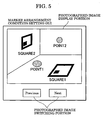
- Fig. 5 is a diagram illustrating a GUI (Graphical User Interface) for setting multiple markers present on the same plane.
- GUI Graphic User Interface
- Fig. 6 is a diagram illustrating a camera coordinate system and an image coordinate system.
- Fig. 8 is a diagram illustrating a plane definition method.
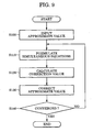
- Fig. 9 is a flowchart illustrating procedures for obtaining the positions of point markers, and the positions and orientations of square markers, according to the first example.
- Fig. 10 is a diagram illustrating a case in which two planes constraining markers exist.
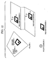
- Fig. 11 is a diagram illustrating marker placements to which a preferred embodiment can be applied.
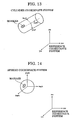
- Fig. 14 is a diagram illustrating a marker being constrained on a spherical surface.
- a marker position-and-orientation calculating unit 250 calculates the position and orientation of each marker so as to satisfy the constraint condition regarding the position of markers set by the marker placement condition setting unit 240 based on the marker detection results of the marker detecting-and-identifying unit 230.
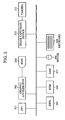
- Fig. 3 is a block diagram illustrating the hardware configuration of the marker position-and-orientation estimating device 2 according to the present example.
- the hardware configuration illustrated in Fig. 3 is the same configuration as that of a common personal computer, but is further connected with an image capturing device 310 and a camera 311.
- the image capturing device 310 is for inputting an image photographed by the camera 311 to the computer, and corresponds to the image capturing unit 220.
- An example of the image capturing device 310 is a video capturing board, but is not restricted to this as long as an image photographed by a camera can be input.
- a CPU 301 serves as the marker detecting-and-identifying unit 230, marker placement condition setting unit 240, and marker position-orientation calculating unit 250 by executing a program stored in an unshown optical medium, external storage device, or the like.
- the hardware configuration of the marker position-and-orientation estimating device 2 shown in Fig. 3 may also include other conventional computer components, such as a graphic accelerator 302 in communication with a head-mounted display (HMD) 304, a storage device, such as a disk 305, a read-only memory (ROM) 306, a random access memory (RAM) 307, and one or more input devices, such as a keyboard 309 and a mouse 308.
- a graphic accelerator 302 in communication with a head-mounted display (HMD) 304, a storage device, such as a disk 305, a read-only memory (ROM) 306, a random access memory (RAM) 307, and one or more input devices, such as a keyboard 309 and a mouse 308.
- HMD head-mounted display
- ROM read-only memory
- RAM random access memory
- Figs. 4A and 4B are diagrams illustrating markers to be employed with the present example.
- Fig. 4A illustrates a point marker in which the placement information is represented by the position of a point in 3-D space. Let us say that point markers have a circular shape having a single color so as to be detected within an image, and the center of gravity of each point marker represents the position thereof in 3-D space.
- Fig. 4B illustrates a plane marker of which the placement information is represented by the position and orientation of a plane in 3-D space.
- the present embodiment employs square markers as plane markers, but plane markers are not restricted to square markers, so any shaped markers may be employed as long as markers have a form of a planar shape.
- the center of a square i.e., the intersecting point of two diagonal lines, represents the position of a square marker in 3-D space.
- the coordinate system of the square marker is assigned so that the x axis and y axis can be parallel to the two sides, and the orientation of the coordinate system of the square marker to the reference coordinate system is taken as the orientation of the square marker.
- the square markers according to the present example are surrounded with a black frame so as to be easily detected on an image, so a square within the black frame is employed as a square marker.
- a user photographs many images of a scene in which markers are disposed using the imaging unit 210.
- the photographed images are input to the computer by the image capturing unit 220.
- the marker detecting-and-identifying unit 230 detects markers from the photographed images input to the computer, and performs identification thereof.
- the term "detection of a marker” means to obtain the image coordinates of a marker on a 2-D image. In the case of point markers, the image coordinates of the center of gravity of marker region on an image are obtained, and, in the case of square markers, the image coordinates of each vertex are obtained.
- the image coordinates of a marker may be obtained automatically, or may be manually specified, for example, by the user clicking on the image with a mouse.
- identification of a marker means to identify a marker to be detected within an image as a unique marker. Identification of a marker may be performed automatically, or may be performed manually by the user. In the case of identifying a point marker automatically, for example, multiple markers having different colors are employed, and identification is performed based on the labeling color of the marker region at the time of detection of markers. Also, in the case of identifying a square marker automatically, for example, identification is performed by giving a unique pattern to each marker.
- a constraint condition that multiple markers exist on the same plane is given as a constraint condition regarding the placement of markers.
- a plane employed here is an unknown plane, and multiple unknown planes exist.
- Fig. 5 illustrates a GUI (Graphical User Interface) for setting multiple markers present on the same plane.
- a photographed image switching portion exists on the GUI, where an image photographed by the imaging unit is displayed. Display of a photographed image may be switched with a button on the photographed image switching portion. Upon the user clicking a Previous button with the mouse, the previous photographed image is displayed. Upon the user clicking a Next button, the subsequent photographed image is displayed.
- Fig. 5 illustrates the case that a photographed image in which two point markers (POINT1 and POINT2 in the drawing) and two square markers (SQUARE1 and SQUARE2 in the drawing) are photographed is displayed on the photographed image display portion. Let us say that of these markers, the point marker POINT1 and the square marker SQUARE1 exist on the same plane. The user selects either POINT1 or SQUARE1 within the photographed image by clicking near either marker with the mouse. The name of the selected marker is changed to bold face.
- the user forms a group from markers on the same plane by clicking nearby markers present on the same plane with the left mouse button as the selected marker while depressing the shift key.
- the name display of all of the markers belonging to the group is changed to bold face.
- the marker can be added to the group by the user clicking another marker with the left mouse button while depressing the shift key.
- the user clicking nearby a marker belonging to a group with the right mouse button while depressing the shift key releases the marker from the group, and the user clicking the same marker with the right mouse button without depressing the shift key releases the entire group.
- Fig. 6 is a diagram illustrating the camera coordinate system and the image coordinate system. Let us say that the intersecting point between the viewing axis and an image surface is taken as the origin O i of the image coordinate system, the horizontal direction of an image is taken as the x i axis, and the vertical direction of the image is taken as the y i axis.
- u x - f ⁇ x c z c
- u y - f ⁇ y c z c
- Expression 1 represents that a point in space, the projected point of the point on an image, and a camera position (viewpoint) exist on the same straight line, and is also referred to as a collinear condition.
- F and G become functions regarding the camera position t, camera orientation ⁇ , and position t pn of a point marker on the reference coordinate system.
- F t x t y t z ⁇ x ⁇ y ⁇ z t pnx t pny t pnz 0
- G t x t y t z ⁇ x ⁇ y ⁇ z t pnx t pny t pnz 0
- F and G become functions regarding the camera position t, camera orientation ⁇ , position t p of a square marker, and orientation ⁇ s of a square marker.
- F t x t y t z ⁇ x ⁇ y ⁇ z t sx t sy t sz ⁇ sx ⁇ sy ⁇ sz 0
- G t x t y t z ⁇ x ⁇ y ⁇ z t sx t sy t sz ⁇ sx ⁇ sy ⁇ sz 0
- n the normal line vector of the plane.
- x w and x p are functions of r.
- x p is identical with t pl p .
- x p y p 0 t pl px t pl py 0
- x w is a function of t pl s , ⁇ pl , and r
- F and G become functions of the camera position t, camera orientation ⁇ , position t pl s of the square marker on the plane, orientation ⁇ pl of the square marker on the plane, and parameter r of the plane, as in Expression (19).
- F t x t y t z ⁇ x ⁇ y ⁇ z t pl sx t pl sy ⁇ pl r ⁇ ⁇ 0
- G t x t y t z ⁇ x ⁇ y ⁇ z t pl sx t pl sy ⁇ pl r ⁇ ⁇ 0
- Expressions (10), (12), (17), and (19) are nonlinear expressions regarding the camera position and orientation, position and orientation of the marker, and the plane parameter. Accordingly, linearization is performed in the vicinity of the approximate values regarding the position and orientation of the camera, the position and orientation of the marker, and the plane parameters using the Taylor expansion up to first order, and the position and orientation of the camera, the position and orientation of the marker, and the plane parameters are obtained using repeated calculation.
- Expressions (20), (21), (22), and (23) are obtained by linearizing the corresponding Expressions (10), (12), (17), and (19) respectively.
- ⁇ t x , ⁇ t y , and ⁇ t z represent the correction value for the approximate values of the position of the camera; ⁇ x , ⁇ y , and ⁇ z for the orientation of the camera; ⁇ t px , ⁇ t py , and ⁇ t pz for the position of the point marker not constrained to the plane; ⁇ t sx , ⁇ t sy , and ⁇ t sz for the position of the square marker not constrained to the plane; ⁇ ⁇ sx , ⁇ sy , and ⁇ sz for the orientation of the square marker not constrained to the plane; ⁇ t pl px and ⁇ t pl py for the position on the plane of the point marker constrained to the plane; ⁇ t pl sx and ⁇ t pl sy for the position on
- F 0 and G 0 in Expressions (20), (21), (22), and (23) are constants, and represent the difference between the observed position u o and the projected position (calculated position) of the marker obtained from the approximate values regarding the position and orientation of the camera, the position of the point marker or the position and orientation of the square marker, and the plane parameters.
- Expressions (20), (21), (22), and (23) are observation equations regarding one point marker or one vertex of a square marker observed on a certain image. In reality, multiple point markers or multiple square markers are observed on multiple images, so multiple Expressions (20), (21), (22), and (23) are obtained.
- the positions and orientations of the cameras, the positions of the point markers not constrained on the plane, the positions and orientations of the square markers not constrained on the plane, the positions of the point markers constrained on the plane, the positions and orientations of the square markers constrained on the plane, and the plane parameters are obtained by solving multiple Expressions (20), (21), (22), and (23) as simultaneous equations regarding the correction values as to the approximate values regarding the positions and orientations of the cameras, the positions of the point markers not constrained on the plane, the positions and orientations of the square markers not constrained on the plane, the positions of the point markers constrained on the plane, the positions and orientations of the square markers constrained on the plane, and the plane parameters.
- Step S110 formulation of simultaneous equations for simultaneously obtaining the correction value of each approximate value is performed so as to minimize the projection error based on the approximate values regarding the positions and orientations of the cameras, the positions of the point markers, the positions and orientations of the square markers, and the plane parameters.
- Step S120 the correction value of each approximate value is obtained from the simultaneous equations formulated in Step S110.
- Step S130 new approximate values are obtained by correcting each approximate value with the corresponding correction value obtained in Step S120.
- Step S140 determination is made as to whether or not the approximate values regarding the positions and orientations of the cameras, the positions of the point markers, the positions and orientations of the square markers, and the plane parameters are converged to the optimized value in Step S130. If so, processing ends. If not, processing returns to Step S110 and steps S110 - S140 are repeated. More specific descriptions regarding each step are provided below.
- Step S100 the approximate values regarding the position and orientation of the camera taking the images, the positions of the point markers, the positions and orientations of the square markers, and the plane parameters are input.
- N the number of images taken
- the number of the point markers not constrained on the plane is K p1
- the number of the point markers constrained on the plane is K p2
- the number of the square markers not constrained on the plane is K s1
- the number of the square markers constrained on the plane is K s2
- the approximate values of the position and orientation of each camera may be obtained from the output value of a 6-degree-of-freedom position and orientation sensor such as a magnetic sensor, which is mounted on the camera, or may be obtained from the correspondence between points of which the positions in the reference coordinate system are known, and the projected position of the point on the image. In the case of employing a point of which the position in the reference coordinate system is known, both the point of which the position is known, and markers of which the positions to be obtained are unknown are mixed in the scene. Alternately, the approximate values of the position and orientation of each camera may be obtained based on the later-described approximate values of the position and orientation of a marker.
- the approximate values of the position and orientation of each marker may be a rough value measured by hand using a measuring tape, ruler, protractor, or surveying instrument, or may be a value estimated once using the method according to the present example or the like.
- the approximate values of the position and orientation of each marker constrained on the plane may be the values of the position and orientation of the marker in the plane coordinate system.
- the approximate values of the plane parameters may be obtained by obtaining a regression plane from the approximate value of the position of each point marker.
- the approximate values of the plane parameters may be obtained from the position and orientation of each square marker by assuming that each square marker is the plane. Further, the user may specify the plane parameters directly without obtaining the plane parameters from the approximate values of the position and orientation of each marker.
- Step S110 observation equations of Expressions (20), (21), (22), and (23) are formulated of a number corresponding to the number of the markers to be observed on the image.
- Expressions (20), (21), (22), and (23) are observation equations regarding the correction values of the position and orientation of one camera, the correction value of the position of one point marker or the correction values of the position and orientation of one square marker, and the correction value of one plane parameter.
- J is called a "Jacobian matrix" in which partial differential coefficients regarding the position and orientation of a camera, the position of a point marker, the position and orientation of a square marker, and a plane parameter, of F and G are arrayed.
- the number of rows of the Jacobian matrix J is the number of the observation equations, i.e., 2 ⁇ (D p + 4 ⁇ D s ), the number of columns thereof is the number of unknowns, i.e., (6 ⁇ N + 3 ⁇ K p1 + 2 ⁇ K p2 + 6 ⁇ K s1 + 3 ⁇ K s2 + 3 ⁇ P).
- ⁇ represents a correction vector.
- the size of the correction vector is the number of unknowns, i.e., (6 ⁇ N + 3 ⁇ K p1 + 2 ⁇ K p2 + 6 ⁇ K s1 + 3 ⁇ K s2 + 3 ⁇ P).
- E represents an error vector, and has -F 0 and -G 0 which are the differences between the calculated position of the projected position due to the approximate value and the observed position.
- the size of E is the number of the observation equations, i.e., 2 ⁇ (D p + 4 ⁇ D s ).
- the origin, scale, and orientation of the reference coordinate system can be clearly specified by photographing point markers of which the positions are known or square markers of which the positions and orientations are known in the reference coordinate system simultaneously.
- Expression (24) the partial differential coefficients regarding the positions and orientations of these markers become zero.
- three point markers, of which the positions are known need to be employed in the case of point markers, or one square marker of which the position and orientation are known needs to be employed in the case of square marker's.
- Step S120 the correction values as to the approximate values regarding the positions and orientations of the cameras, the positions of the point markers, the positions and orientations of the square markers, and the plane parameters, are obtained using Expression (26).
- the correction value vector ⁇ is obtained by multiplying both sides of Expression (26) by the inverse matrix of the matrix J.
- the correction value vector ⁇ is obtained using the least mean square method, as shown in Expression (27).
- ⁇ J t ⁇ J - 1 ⁇ J t ⁇ E
- J FXc The Jacobian matrix J FXc of which each factor has a partial differential coefficient according to x c , y c , and z c of F and G, can be written as shown in Expression (29).
- J XcR is the Jacobian matrix as shown in Expression (33).
- J x , R ⁇ x c ⁇ R 11 ⁇ x c ⁇ R 21 ⁇ x c ⁇ R 31 ⁇ x c ⁇ R 12 ⁇ x c ⁇ R 22 ⁇ x c ⁇ R 32 ⁇ x c ⁇ R 13 ⁇ x c ⁇ R 23 ⁇ x c ⁇ R 33 ⁇ y c ⁇ R 11 ⁇ y c ⁇ R 21 ⁇ y c ⁇ R 31 ⁇ y c ⁇ R 12 ⁇ y c ⁇ R 22 ⁇ y c ⁇ R 32 ⁇ y c ⁇ R 13 ⁇ y c ⁇ R 23 ⁇ y c ⁇ R 33 ⁇ z c ⁇ R 11 ⁇ z c ⁇ R 21 ⁇ z c ⁇ R 31 ⁇ z c ⁇ R 12 ⁇ z c ⁇
- J Rraxis is the Jacobian matrix as shown in Expression (34).
- J Rx axis ⁇ R 11 ⁇ r x ⁇ R 11 ⁇ r y ⁇ R 11 ⁇ r z ⁇ R 11 ⁇ r a ⁇ R 21 ⁇ r x ⁇ R 21 ⁇ r x ⁇ R 21 ⁇ r z ⁇ R 21 ⁇ r a ⁇ R 31 ⁇ r x ⁇ R 31 ⁇ r y ⁇ R 31 ⁇ r z ⁇ R 31 ⁇ r x ⁇ R 12 ⁇ r x ⁇ R 12 ⁇ r y ⁇ R 12 ⁇ r z ⁇ R 12 ⁇ r a ⁇ R 22 ⁇ r x ⁇ R 22 ⁇ r y ⁇ R 22 ⁇ r z ⁇ R 22 ⁇ r a ⁇ R 32 ⁇ r x ⁇ R 32 ⁇ r y ⁇ R 32 ⁇ r
- J ⁇ is the Jacobian matrix as shown in Expression (36).
- the positions and orientations of markers can be obtained accurately by obtaining the positions and orientations of the markers so as to satisfy the constraint condition.
- Fig. 10 illustrates the case in which two planes constraining markers exist.
- R p ⁇ 2 R 11 p ⁇ 2 R 12 p ⁇ 2 R 13 p ⁇ 2 R 21 p ⁇ 2 R 22 p ⁇ 2 R 23 p ⁇ 2 R 31 p ⁇ 2
- ⁇ 2 can be obtained with ⁇ 2 and ⁇ from Expression (49).
- the observation equations of point markers and square markers constrained on the plane 1 are the same as Expressions (22) and (23) according to the first example.
- the plane 2 becomes the functions of r 2 and ⁇ 2 , so the observation equations of point markers and square markers constrained on the plane 2 are represented as shown in Expression (50) and Expression (51), respectively.
- simultaneous equations are formulated based on observation equations (22), (23), (50), and (51), correction values as to the approximate values regarding the positions and orientations of the cameras, the positions and orientations of the markers, the three parameters of the plane 1, and the two parameters of the plane 2 are obtained, and the approximate values are optimized using repeated calculation.
- ⁇ 2 from Expression (49)
- two solutions having a different sign are obtained, but of these two solutions of ⁇ 2 , the one solution reducing projection error as to ⁇ 2 obtained for each repeated calculation more than the other is employed as the solution.
- Fig. 11 is a diagram illustrating marker placements to which the preferred embodiment can be applied.
- the normal vectors of the four square markers i.e., the direction of the z s axis of each square marker is the same.
- the normal vector directions of the square markers will be represented with ⁇ and ⁇ .
- the normal vector is a vector obtained by the unit vector of the z axis in the reference coordinate system being rotated around the x axis by ⁇ , and then being rotated around the y axis by ⁇ .
- ⁇ and ⁇ have the common value for the multiple square markers having the same normal vector direction. If we say that the rotation around the z axis of each square marker is ⁇ , the orientation R s of the square marker as to the reference coordinate system is represented with Expression (52).
- the position in the reference coordinate system of each vertex of each square marker forms the function of the normal vector directions ⁇ and ⁇ , z-axial orientation of the square markers ⁇ , and the position t s in the reference coordinate system of each square marker. Accordingly, the observation equation of each vertex of a square marker of which the normal vector being constrained is represented with Expression (54).
- the positions and orientations of the markers can be obtained so as to satisfy the constraint condition.
- Fig. 12 is a diagram illustrating marker placements to which the present example can be applied.
- the drawing illustrates the case in which a point marker 1 and a square marker 1 exist on the same plane (plane 1), a square marker 2 and a square marker 3 have the common normal vector direction, and a point marker 2 and a square marker 4 have no constraint conditions regarding placement thereof.
- observation equation (22) holds for the point marker 1, observation equation (23) for the square marker 1, observation equation (54) for the square markers 2 and 3, observation equation (20) for the point marker 2, and observation equation (21) for the square marker 4.
- Expressions (20) through (23) and (54) are observation equations regarding the correction value of the position and orientation of one camera, the correction value of the position and orientation of one marker, the correction value of one plane parameter, and the correction value of one normal vector direction.
- Expression (55) serving as an observation equation is formulated for each point marker, and each vertex of each square marker detected on the photographed images, and is solved as simultaneous equations, thus simultaneously obtaining correction values corresponding to the approximate values regarding a camera position t i , camera orientation ⁇ i , placement-unconstrained point marker position t pi , placement-unconstrained square marker position t si , orientation ⁇ si , on-plane-constrained point marker position t pl p i , on-plane-constrained square marker position t pl si , orientation ⁇ pl i , normal-vector-constrained square marker position t v si , orientation ⁇ i , plane parameter r i , normal vector directions ⁇ v i and ⁇ v i , and optimizing the approximate values by repeating correction of the approximate values using repeated calculation.
- a GUI (Graphical User Interface) for setting the marker placement conditions according to the present example is illustrated in Figs. 15A through 15C .
- grouping of markers, and the constraint condition type of each group can be set.
- the GUI in Figs. 15A through 15C further include a function for setting a constraint condition type in addition to the GUI in Fig. 5 .
- a dialog box Fig. 15B for selecting a constraint condition is displayed.
- a constraint condition e.g., plane constraint, normal vector constraint, straight line constraint
- a constraint condition e.g., plane constraint, normal vector constraint, straight line constraint
- a menu as illustrated in Fig. 15C may be employed instead of the dialog box illustrated in Fig. 15B .
- the positions and orientations of markers can be obtained so as to satisfy all of the constraint conditions.
- the positions and orientations of the markers can be accurately obtained.
- a marker may be constrained on the side face of a cylinder.
- the origin is taken in the center of the cylinder coordinate system, and the cylinder coordinate system is taken as illustrated in the drawing.
- the orientation of the cylinder is represented with a rotation ⁇ around the x axis and a rotation ⁇ around the y axis.
- a rotation matrix R cy1 representing the orientation of the cylinder is represented as shown in Expression (56).
- R cyl R cyl ⁇ 11 R cyl ⁇ 12 R cyl ⁇ 13 R cyl ⁇ 21 R cyl ⁇ 22 R cyl ⁇ 23 R cyl ⁇ 31 R cyl ⁇ 32 R cyl ⁇ 33 + cos ⁇ 0 sin ⁇ 0 1 0 - sin ⁇ 0 cos ⁇ ⁇ 1 0 0 0 cos ⁇ - sin ⁇ 0 sin ⁇ cos ⁇
- x w y w z w 1 R cyl ⁇ 11 R cyl ⁇ 12 R cyl ⁇ 13 t x cyl R cyl ⁇ 21 R cyl ⁇ 22 R cyl ⁇ 23 t y cyl R cyl ⁇ 31 R cyl ⁇ 32 R cyl ⁇ 33 t z cyl 0 0 0 1 ⁇ x cyl y cyl z cyl 1
- a point on the side face of the cylinder is represented with Expression (58) in the cylinder coordinate system, from the rotation angle ⁇ around the Z cyl axis, the z cyl coordinate d, and a known cylinder radius r cyl .
- x cyl y cyl z cyl r cyl ⁇ cos ⁇ r cyl ⁇ sin ⁇ d
- the projected position of the marker constrained on the side face of the cylinder forms a function regarding the position and orientation of the camera, the position and orientation of the cylinder, and the positions ⁇ and d of the marker on the cylinder, so the position of the marker constrained on the side face of the cylinder can be obtained by solving the observation equation for obtaining these correction values.
- a marker may be constrained on a surface of a sphere.
- the sphere coordinate system is taken at the center of the sphere.
- x w y w z w x sph + t x sph y sph + t y sph z sph + t z sph
- the projected position of the marker constrained on the sphere surface forms a function regarding the position and orientation of the camera, the position of the sphere, and the positions ⁇ and ⁇ of the marker on the sphere surface, so the position of the marker constrained on the sphere surface can be obtained by solving the observation equation for obtaining these correction values.
- s is a variable representing the marker position on the straight line.
- the projected position of the marker constrained on the straight line forms a function regarding the position and orientation of the camera, the point t 1 where the straight line passes through, the directional vector d of the straight line, and the position s of the marker on the straight line, so the position of the marker constrained on the straight line can be obtained by solving the observation equation for obtaining these correction values.
- a method for subjecting observation equations to Taylor expansion, and repeating correction utilizing as far as primary items has been described as a method for correcting marker placement information.
- This is a method for estimating the amount of correction of unknown parameters in the case of assuming that observation equations are subjected to linearization locally in one process of repetition, and result in no error, and is a method equivalent to a method generally known as the Newton method.
- the Newton method is a typical method for solving a nonlinear equation using numerical computation, but a repeated calculation method used for the aforementioned embodiment and examples is not restricted to this.
Claims (10)
- Procédé d'estimation d'informations de positionnement de marqueurs permettant d'estimer des informations de position et d'orientation de marqueurs à partir d'images photographiées, ledit procédé comprenant :une étape de réglage de condition de contrainte destinée à régler une condition de contrainte qui est définie avec une condition géométrique concernant des informations de position et d'orientation de marqueurs ;une étape d'acquisition destinée à acquérir des images photographiées d'une scène comprenant des images de marqueurs ;une étape de détection de marqueurs destinée à détecter des marqueurs sur lesdites images photographiées ;une étape de calcul destinée à calculer des positions tridimensionnelles desdits marqueurs et des positions bidimensionnelles desdits marqueurs projetées sur les images photographiées ; etune étape d'estimation destinée à estimer les informations de position et d'orientation desdits marqueurs en résolvant un système d'équations représentant des erreurs entre les positions détectées et les positions projetées calculées desdits marqueurs, dans lequel le système d'équations comprend les positions et les orientations des marqueurs en tant que paramètres inconnus et respecte ladite condition de contrainte ;dans lequel ladite condition de contrainte est représentée par une équation représentant la condition de contrainte, et les informations de position et d'orientation respectant ladite condition de contrainte sont représentées par un ensemble de paramètres d'informations de positionnement respectant ladite condition de contrainte,dans lequel des marqueurs présents dans l'espace de la scène sont des marqueurs dont le vecteur de la droite normale peut être défini, etdans lequel ladite condition de contrainte est une condition de contrainte selon laquelle les directions des vecteurs des droites normales d'une pluralité de marqueurs sont identiques, l'équation représentant ladite condition de contrainte est une équation du vecteur de la droite normale, et ledit ensemble de paramètres d'informations de positionnement comprend un angle de rotation et le vecteur de la droite normale.
- Procédé d'estimation d'informations de positionnement de marqueurs selon la revendication 1, dans lequel la condition de contrainte est réglée en fonction d'instructions de l'utilisateur lors de ladite étape de réglage, dans lequel lesdites instructions de l'utilisateur comprennent le regroupement de marqueurs, et le regroupement de marqueurs est contraint par rapport à la condition de contrainte tandis que les autres marqueurs ne sont pas ainsi contraints.
- Procédé d'estimation d'informations de positionnement de marqueurs selon la revendication 2, dans lequel lesdites instructions de l'utilisateur comprennent des types de conditions de contrainte.
- Programme qui, lorsqu'il est chargé dans un ordinateur et exécuté, met en oeuvre un procédé selon l'une quelconque des revendications précédentes.
- Support d'enregistrement stockant un programme selon la revendication 4.
- Dispositif d'estimation d'informations de positionnement de marqueurs (2) destiné à estimer les informations de position et d'orientation de marqueurs à partir d'images photographiées, ledit dispositif comprenant :un moyen de réglage de condition de contrainte (240) destiné à régler une condition de contrainte qui est définie avec une condition géométrique concernant les informations de position et d'orientation de marqueurs ;un moyen d'acquisition (210, 220) destiné à acquérir des images photographiées d'une scène comprenant des images de marqueurs ;un moyen de détection de marqueurs (230) destiné à détecter des marqueurs sur lesdites images photographiées ;un moyen de calcul (250) ayant pour fonction de calculer des positions tridimensionnelles desdits marqueurs et des positions bidimensionnelles desdits marqueurs projetées sur les images photographiées ; etun moyen d'estimation (250) destiné à estimer les informations de position et d'orientation desdits marqueurs en résolvant un système d'équations représentant des erreurs entre les positions détectées et les positions projetées calculées desdits marqueurs, dans lequel le système d'équations comprend les positions et les orientations des marqueurs en tant que paramètres inconnus et respecte ladite condition de contrainte ;dans lequel ladite condition de contrainte est représentée par une équation représentant la condition de contrainte, et les informations de position et d'orientation respectant ladite condition de contrainte sont représentées par un ensemble de paramètres d'informations de positionnement respectant ladite condition de contrainte,dans lequel des marqueurs présents dans l'espace de la scène sont des marqueurs dont le vecteur de la droite normale peut être défini ; etdans lequel ladite condition de contrainte est une condition de contrainte selon laquelle les directions des vecteurs des droites normales d'une pluralité de marqueurs sont identiques, l'équation représentant ladite condition de contrainte est une équation du vecteur de la droite normale, et ledit ensemble de paramètres d'informations de positionnement comprend un angle de rotation et le vecteur de la droite normale.
- Dispositif d'estimation d'informations de positionnement de marqueurs selon la revendication 6, comprenant en outré :un moyen de calcul de position projetée de marqueur destiné à calculer la position à laquelle un marqueur est projeté sur la surface d'une image sur la base d'une valeur approximative de la position et de l'orientation d'une unité de formation d'image de ladite image photographiée et de la valeur approximative des informations de positionnement du marqueur ;un moyen de calcul de valeur de correction destiné à obtenir une valeur de correction permettant de corriger les informations de position et d'orientation d'un marqueur afin de réduire une marge d'erreur entre la position du marqueur détectée sur la surface de l'image par ledit moyen de détection de marqueur, et la position projetée du marqueur obtenue sur la surface de l'image par ledit moyen de calcul de position projetée du marqueur, ainsi que pour respecter la condition de contrainte de marqueurs réglée par ledit moyen de réglage de condition de contrainte ;un moyen de correction d'informations de positionnement destiné à corriger les informations de position et d'orientation d'un marqueur sur la base de la valeur de correction obtenue par ledit moyen de calcul de valeur de correction ; etun moyen de calcul répété destiné à calculer les informations de position et d'orientation d'un marqueur en effectuant de manière répétée l'exécution du calcul dudit moyen de calcul de position projetée du marqueur, dudit moyen de calcul de valeur de correction et dudit moyen de correction d'informations de positionnement en utilisant les informations de position et d'orientation du marqueur corrigées par ledit moyen de correction d'informations de positionnement au lieu d'une valeur approximative dudit moyen de calcul de position projetée du marqueur.
- Dispositif d'estimation d'informations de positionnement de marqueurs selon la revendication 6, dans lequel ladite condition de contrainte est une condition de contrainte selon laquelle des marqueurs sont présents sur le même plan inconnu, l'équation représentant ladite condition de contrainte est l'équation d'un plan, et ledit ensemble de paramètres d'informations de positionnement comprennent un angle de rotation autour du vecteur de la droite normale du plan et une position sur le plan.
- Dispositif d'estimation d'informations de positionnement de marqueurs selon la revendication 6, dans lequel lesdits marqueurs ont des formes carrées.
- Dispositif d'estimation d'informations de positionnement de marqueurs selon la revendication 6, dans lequel il existe une pluralité desdites conditions de contrainte, et les informations de position et d'orientation dudit marqueur sont estimées par obtention de l'équation représentant chaque condition de contrainte et du paramètre d'informations de positionnement dudit marqueur concernant la dite pluralité de conditions de contrainte.
Applications Claiming Priority (2)
| Application Number | Priority Date | Filing Date | Title |
|---|---|---|---|
| JP2004144891A JP4522140B2 (ja) | 2004-05-14 | 2004-05-14 | 指標配置情報推定方法および情報処理装置 |
| JP2004144891 | 2004-05-14 |
Publications (3)
| Publication Number | Publication Date |
|---|---|
| EP1596329A2 EP1596329A2 (fr) | 2005-11-16 |
| EP1596329A3 EP1596329A3 (fr) | 2006-02-22 |
| EP1596329B1 true EP1596329B1 (fr) | 2010-09-08 |
Family
ID=34941235
Family Applications (1)
| Application Number | Title | Priority Date | Filing Date |
|---|---|---|---|
| EP05252877A Not-in-force EP1596329B1 (fr) | 2004-05-14 | 2005-05-11 | Procédé pour estimer une information de position de repère d'image et dispositif pour le traitement d'informations |
Country Status (5)
| Country | Link |
|---|---|
| US (1) | US7657065B2 (fr) |
| EP (1) | EP1596329B1 (fr) |
| JP (1) | JP4522140B2 (fr) |
| CN (1) | CN100338632C (fr) |
| DE (1) | DE602005023374D1 (fr) |
Families Citing this family (51)
| Publication number | Priority date | Publication date | Assignee | Title |
|---|---|---|---|---|
| JP4914019B2 (ja) * | 2005-04-06 | 2012-04-11 | キヤノン株式会社 | 位置姿勢計測方法及び装置 |
| WO2007004521A1 (fr) * | 2005-06-30 | 2007-01-11 | Olympus Corporation | Dispositif et procédé de spécification de repère |
| US7656425B2 (en) * | 2006-03-31 | 2010-02-02 | Mitutoyo Corporation | Robust field of view distortion calibration |
| JP4958497B2 (ja) * | 2006-08-07 | 2012-06-20 | キヤノン株式会社 | 位置姿勢測定装置及び位置姿勢測定方法、複合現実感提示システム、コンピュータプログラム及び記憶媒体 |
| JP4926817B2 (ja) * | 2006-08-11 | 2012-05-09 | キヤノン株式会社 | 指標配置情報計測装置および方法 |
| WO2008036354A1 (fr) | 2006-09-19 | 2008-03-27 | Braintech Canada, Inc. | Système et procédé de détermination de la pose d'un objet |
| JP4810403B2 (ja) * | 2006-11-08 | 2011-11-09 | キヤノン株式会社 | 情報処理装置、情報処理方法 |
| KR100906974B1 (ko) * | 2006-12-08 | 2009-07-08 | 한국전자통신연구원 | 카메라를 이용한 위치 인식 장치 및 그 방법 |
| WO2008076942A1 (fr) * | 2006-12-15 | 2008-06-26 | Braintech Canada, Inc. | Système et procédé d'identification d'objets |
| JP4886560B2 (ja) * | 2007-03-15 | 2012-02-29 | キヤノン株式会社 | 情報処理装置、情報処理方法 |
| JP5196825B2 (ja) * | 2007-03-29 | 2013-05-15 | キヤノン株式会社 | 画像処理装置、画像処理方法 |
| US20080266323A1 (en) * | 2007-04-25 | 2008-10-30 | Board Of Trustees Of Michigan State University | Augmented reality user interaction system |
| US20080306708A1 (en) * | 2007-06-05 | 2008-12-11 | Raydon Corporation | System and method for orientation and location calibration for image sensors |
| KR100903629B1 (ko) | 2007-07-03 | 2009-06-18 | 주식회사 에이알맥스 | 공선조건식을 이용한 단영상으로부터 개체의 3차원 정보추출 방법, 이를 수행하는 프로그램을 기록한 기록매체 및공선조건식을 이용한 단영상으로부터 개체의 3차원 정보추출 시스템 |
| US7957583B2 (en) * | 2007-08-02 | 2011-06-07 | Roboticvisiontech Llc | System and method of three-dimensional pose estimation |
| US9058764B1 (en) * | 2007-11-30 | 2015-06-16 | Sprint Communications Company L.P. | Markers to implement augmented reality |
| US8542906B1 (en) | 2008-05-21 | 2013-09-24 | Sprint Communications Company L.P. | Augmented reality image offset and overlay |
| KR101465668B1 (ko) * | 2008-06-24 | 2014-11-26 | 삼성전자주식회사 | 단말 및 그의 블로깅 방법 |
| JP2010025759A (ja) * | 2008-07-18 | 2010-02-04 | Fuji Xerox Co Ltd | 位置計測システム |
| US8559699B2 (en) * | 2008-10-10 | 2013-10-15 | Roboticvisiontech Llc | Methods and apparatus to facilitate operations in image based systems |
| US8155387B2 (en) * | 2008-10-13 | 2012-04-10 | International Business Machines Corporation | Method and system for position determination using image deformation |
| KR101128913B1 (ko) * | 2009-05-07 | 2012-03-27 | 에스엔유 프리시젼 주식회사 | 비전 검사시스템 및 이를 이용한 좌표변환방법 |
| KR101082285B1 (ko) * | 2010-01-29 | 2011-11-09 | 주식회사 팬택 | 증강 현실 제공 단말기 및 방법 |
| JPWO2011111122A1 (ja) * | 2010-03-12 | 2013-06-27 | 富士通株式会社 | 取付作業支援装置、方法、及びプログラム |
| EP2547278B2 (fr) * | 2010-03-17 | 2019-10-23 | Brainlab AG | Commande de flux dans une chirurgie assistée par ordinateur sur la base de positions de marqueur |
| US9158777B2 (en) | 2010-03-30 | 2015-10-13 | Gravity Jack, Inc. | Augmented reality methods and apparatus |
| CN101872470B (zh) * | 2010-05-30 | 2011-12-28 | 李滨 | 一种ct或mri图像的矫正和靶点定位方法 |
| US20120223968A1 (en) * | 2010-10-12 | 2012-09-06 | Kazutoshi Kashimoto | Display processing device, display method, and program |
| KR101295712B1 (ko) * | 2010-11-22 | 2013-08-16 | 주식회사 팬택 | 증강 현실 사용자 인터페이스 제공 장치 및 방법 |
| KR101269773B1 (ko) * | 2010-12-13 | 2013-05-30 | 주식회사 팬택 | 증강 현실 제공 단말기 및 방법 |
| US8937628B2 (en) | 2011-06-21 | 2015-01-20 | Siemens Energy, Inc. | Mapping of a contour shape to an X and Y coordinate system |
| JP5988563B2 (ja) * | 2011-10-25 | 2016-09-07 | キヤノン株式会社 | 画像処理装置と画像処理装置の制御方法およびプログラムと、情報処理装置と情報処理装置の制御方法およびプログラム |
| KR101874895B1 (ko) * | 2012-01-12 | 2018-07-06 | 삼성전자 주식회사 | 증강 현실 제공 방법 및 이를 지원하는 단말기 |
| US8922589B2 (en) | 2013-04-07 | 2014-12-30 | Laor Consulting Llc | Augmented reality apparatus |
| US9191620B1 (en) | 2013-12-20 | 2015-11-17 | Sprint Communications Company L.P. | Voice call using augmented reality |
| CN110989284A (zh) * | 2014-04-22 | 2020-04-10 | 日本电信电话株式会社 | 视频呈现装置、视频呈现方法以及程序 |
| US9508195B2 (en) * | 2014-09-03 | 2016-11-29 | Microsoft Technology Licensing, Llc | Management of content in a 3D holographic environment |
| US9734634B1 (en) * | 2014-09-26 | 2017-08-15 | A9.Com, Inc. | Augmented reality product preview |
| JP6564622B2 (ja) * | 2015-06-04 | 2019-08-21 | 株式会社大林組 | 三次元位置計測方法、測量方法、三次元位置計測装置及び三次元位置計測プログラム |
| US10424117B2 (en) * | 2015-12-02 | 2019-09-24 | Seiko Epson Corporation | Controlling a display of a head-mounted display device |
| WO2017110071A1 (fr) * | 2015-12-25 | 2017-06-29 | パナソニックIpマネジメント株式会社 | Dispositif de mesure de taille, appareil de boîte de livraison et procédé de mesure de taille |
| US10072934B2 (en) | 2016-01-15 | 2018-09-11 | Abl Ip Holding Llc | Passive marking on light fixture detected for position estimation |
| JP6688088B2 (ja) * | 2016-01-19 | 2020-04-28 | キヤノン株式会社 | 情報処理装置およびその制御方法 |
| JP6166409B1 (ja) * | 2016-03-16 | 2017-07-19 | ヤフー株式会社 | 画像処理装置、画像処理方法及び画像処理プログラム |
| US20180268614A1 (en) * | 2017-03-16 | 2018-09-20 | General Electric Company | Systems and methods for aligning pmi object on a model |
| CN108596105B (zh) * | 2018-04-26 | 2023-02-03 | 李辰 | 增强现实书画系统 |
| US11600022B2 (en) | 2020-08-28 | 2023-03-07 | Unity Technologies Sf | Motion capture calibration using drones |
| CA3191221A1 (fr) * | 2020-08-28 | 2022-03-03 | Dejan Momcilovic | Etalonnage de capture de mouvement au moyen de drones |
| US11636621B2 (en) | 2020-08-28 | 2023-04-25 | Unity Technologies Sf | Motion capture calibration using cameras and drones |
| US11830219B2 (en) * | 2021-12-29 | 2023-11-28 | Midea Group Co., Ltd. | Joint visual localization and orientation detection method |
| JP2023159484A (ja) | 2022-04-20 | 2023-11-01 | キヤノン株式会社 | 情報処理装置、情報処理システム、情報処理装置の制御方法およびプログラム |
Family Cites Families (22)
| Publication number | Priority date | Publication date | Assignee | Title |
|---|---|---|---|---|
| US6268862B1 (en) * | 1996-03-08 | 2001-07-31 | Canon Kabushiki Kaisha | Three dimensional virtual space generation by fusing images |
| US5889550A (en) * | 1996-06-10 | 1999-03-30 | Adaptive Optics Associates, Inc. | Camera tracking system |
| JPH10222668A (ja) * | 1997-02-04 | 1998-08-21 | Syst Sakomu:Kk | モーションキャプチャ方法およびシステム |
| JPH1184307A (ja) | 1997-09-01 | 1999-03-26 | M R Syst Kenkyusho:Kk | 頭部装着型の光学装置 |
| US6137491A (en) | 1998-06-05 | 2000-10-24 | Microsoft Corporation | Method and apparatus for reconstructing geometry using geometrically constrained structure from motion with points on planes |
| JP3976900B2 (ja) * | 1998-07-23 | 2007-09-19 | キヤノン株式会社 | 視点位置姿勢の決定方法及びカメラ装置 |
| US7084887B1 (en) * | 1999-06-11 | 2006-08-01 | Canon Kabushiki Kaisha | Marker layout method, mixed reality apparatus, and mixed reality space image generation method |
| JP4573977B2 (ja) * | 1999-09-22 | 2010-11-04 | 富士重工業株式会社 | 監視システムの距離補正装置、および監視システムの消失点補正装置 |
| JP3631151B2 (ja) * | 2000-11-30 | 2005-03-23 | キヤノン株式会社 | 情報処理装置、複合現実感提示装置及びその方法並びに記憶媒体 |
| JP3467017B2 (ja) * | 2000-11-30 | 2003-11-17 | キヤノン株式会社 | 位置姿勢の決定方法及び装置並びに記憶媒体 |
| GB2372656A (en) * | 2001-02-23 | 2002-08-28 | Ind Control Systems Ltd | Optical position determination |
| US7379077B2 (en) * | 2001-08-23 | 2008-05-27 | Siemens Corporate Research, Inc. | Augmented and virtual reality guided instrument positioning using along-the-line-of-sight alignment |
| US7274380B2 (en) * | 2001-10-04 | 2007-09-25 | Siemens Corporate Research, Inc. | Augmented reality system |
| JP3796449B2 (ja) * | 2002-01-31 | 2006-07-12 | キヤノン株式会社 | 位置姿勢決定方法および装置並びにコンピュータプログラム |
| EP1349114A3 (fr) * | 2002-03-19 | 2011-06-15 | Canon Kabushiki Kaisha | Appareil d'étalonnage de capteur, méthode d'étalonnage de capteur, programme, support d'enregistrement, méthode de traitement d'information et appareil de traitement d'information |
| EP1354564B1 (fr) * | 2002-04-16 | 2004-09-15 | BrainLAB AG | Marqueur pour un instrument et procédé de localisation d'un marqueur |
| US7190331B2 (en) * | 2002-06-06 | 2007-03-13 | Siemens Corporate Research, Inc. | System and method for measuring the registration accuracy of an augmented reality system |
| JP3944019B2 (ja) * | 2002-07-31 | 2007-07-11 | キヤノン株式会社 | 情報処理装置および方法 |
| JP2004151085A (ja) * | 2002-09-27 | 2004-05-27 | Canon Inc | 情報処理方法及び情報処理装置 |
| JP4136859B2 (ja) * | 2003-01-10 | 2008-08-20 | キヤノン株式会社 | 位置姿勢計測方法 |
| JP4532982B2 (ja) * | 2004-05-14 | 2010-08-25 | キヤノン株式会社 | 配置情報推定方法および情報処理装置 |
| US7734084B2 (en) * | 2006-10-20 | 2010-06-08 | Hewlett-Packard Development Company, L.P. | Method and system for offset estimation and alignment |
-
2004
- 2004-05-14 JP JP2004144891A patent/JP4522140B2/ja not_active Expired - Fee Related
-
2005
- 2005-05-11 DE DE602005023374T patent/DE602005023374D1/de active Active
- 2005-05-11 EP EP05252877A patent/EP1596329B1/fr not_active Not-in-force
- 2005-05-11 US US11/126,916 patent/US7657065B2/en not_active Expired - Fee Related
- 2005-05-16 CN CNB200510068067XA patent/CN100338632C/zh not_active Expired - Fee Related
Non-Patent Citations (1)
| Title |
|---|
| BARATOFF G ET AL: "Interactive multi-marker calibration for augmented reality applications", MIXED AND AUGMENTED REALITY, 2002. ISMAR 2002. PROCEEDINGS. INTERNATIO NAL SYMPOSIUM ON SEPT. 30 - OCT. 1, 2002, PISCATAWAY, NJ, USA,IEEE, 30 September 2002 (2002-09-30), pages 107 - 116, XP010620947, ISBN: 978-0-7695-1781-0 * |
Also Published As
| Publication number | Publication date |
|---|---|
| EP1596329A2 (fr) | 2005-11-16 |
| JP4522140B2 (ja) | 2010-08-11 |
| JP2005327103A (ja) | 2005-11-24 |
| DE602005023374D1 (de) | 2010-10-21 |
| CN1696605A (zh) | 2005-11-16 |
| CN100338632C (zh) | 2007-09-19 |
| US20050253870A1 (en) | 2005-11-17 |
| US7657065B2 (en) | 2010-02-02 |
| EP1596329A3 (fr) | 2006-02-22 |
Similar Documents
| Publication | Publication Date | Title |
|---|---|---|
| EP1596329B1 (fr) | Procédé pour estimer une information de position de repère d'image et dispositif pour le traitement d'informations | |
| US7529387B2 (en) | Placement information estimating method and information processing device | |
| US7664341B2 (en) | Index layout measurement method, position and orientation estimation method, index layout measurement apparatus, and position and orientation estimation apparatus | |
| US8019114B2 (en) | Position and orientation measurement method and apparatus | |
| JP4757142B2 (ja) | 撮影環境校正方法及び情報処理装置 | |
| JP4137078B2 (ja) | 複合現実感情報生成装置および方法 | |
| US7397481B2 (en) | Image display method and image display system | |
| US7928977B2 (en) | Image compositing method and apparatus for superimposing a computer graphics image on an actually-sensed image | |
| JP5248806B2 (ja) | 情報処理装置、情報処理方法 | |
| JP4708752B2 (ja) | 情報処理方法および装置 | |
| US20040176925A1 (en) | Position/orientation measurement method, and position/orientation measurement apparatus | |
| JP2008065807A (ja) | 指標配置情報計測装置および方法 | |
| JP2005326282A (ja) | 位置姿勢計測方法および装置 | |
| JP2007233971A (ja) | 画像合成方法及び装置 | |
| JP2007048068A (ja) | 情報処理方法および装置 | |
| JP4926598B2 (ja) | 情報処理方法、情報処理装置 | |
| JP4810403B2 (ja) | 情報処理装置、情報処理方法 | |
| JP2014215821A (ja) | 情報処理装置、情報処理方法及びプログラム | |
| JP2010118002A (ja) | 情報処理装置及び情報処理方法 |
Legal Events
| Date | Code | Title | Description |
|---|---|---|---|
| PUAI | Public reference made under article 153(3) epc to a published international application that has entered the european phase |
Free format text: ORIGINAL CODE: 0009012 |
|
| AK | Designated contracting states |
Kind code of ref document: A2 Designated state(s): AT BE BG CH CY CZ DE DK EE ES FI FR GB GR HU IE IS IT LI LT LU MC NL PL PT RO SE SI SK TR |
|
| AX | Request for extension of the european patent |
Extension state: AL BA HR LV MK YU |
|
| PUAL | Search report despatched |
Free format text: ORIGINAL CODE: 0009013 |
|
| AK | Designated contracting states |
Kind code of ref document: A3 Designated state(s): AT BE BG CH CY CZ DE DK EE ES FI FR GB GR HU IE IS IT LI LT LU MC NL PL PT RO SE SI SK TR |
|
| AX | Request for extension of the european patent |
Extension state: AL BA HR LV MK YU |
|
| 17P | Request for examination filed |
Effective date: 20060822 |
|
| AKX | Designation fees paid |
Designated state(s): DE FR GB IT NL |
|
| 17Q | First examination report despatched |
Effective date: 20061211 |
|
| GRAP | Despatch of communication of intention to grant a patent |
Free format text: ORIGINAL CODE: EPIDOSNIGR1 |
|
| GRAS | Grant fee paid |
Free format text: ORIGINAL CODE: EPIDOSNIGR3 |
|
| GRAA | (expected) grant |
Free format text: ORIGINAL CODE: 0009210 |
|
| AK | Designated contracting states |
Kind code of ref document: B1 Designated state(s): DE FR GB IT NL |
|
| REG | Reference to a national code |
Ref country code: GB Ref legal event code: FG4D |
|
| REF | Corresponds to: |
Ref document number: 602005023374 Country of ref document: DE Date of ref document: 20101021 Kind code of ref document: P |
|
| REG | Reference to a national code |
Ref country code: NL Ref legal event code: VDEP Effective date: 20100908 |
|
| PG25 | Lapsed in a contracting state [announced via postgrant information from national office to epo] |
Ref country code: NL Free format text: LAPSE BECAUSE OF FAILURE TO SUBMIT A TRANSLATION OF THE DESCRIPTION OR TO PAY THE FEE WITHIN THE PRESCRIBED TIME-LIMIT Effective date: 20100908 |
|
| PG25 | Lapsed in a contracting state [announced via postgrant information from national office to epo] |
Ref country code: IT Free format text: LAPSE BECAUSE OF FAILURE TO SUBMIT A TRANSLATION OF THE DESCRIPTION OR TO PAY THE FEE WITHIN THE PRESCRIBED TIME-LIMIT Effective date: 20100908 |
|
| PLBE | No opposition filed within time limit |
Free format text: ORIGINAL CODE: 0009261 |
|
| STAA | Information on the status of an ep patent application or granted ep patent |
Free format text: STATUS: NO OPPOSITION FILED WITHIN TIME LIMIT |
|
| 26N | No opposition filed |
Effective date: 20110609 |
|
| REG | Reference to a national code |
Ref country code: DE Ref legal event code: R097 Ref document number: 602005023374 Country of ref document: DE Effective date: 20110609 |
|
| REG | Reference to a national code |
Ref country code: FR Ref legal event code: PLFP Year of fee payment: 12 |
|
| REG | Reference to a national code |
Ref country code: FR Ref legal event code: PLFP Year of fee payment: 13 |
|
| PGFP | Annual fee paid to national office [announced via postgrant information from national office to epo] |
Ref country code: FR Payment date: 20170524 Year of fee payment: 13 Ref country code: GB Payment date: 20170517 Year of fee payment: 13 Ref country code: DE Payment date: 20170531 Year of fee payment: 13 |
|
| REG | Reference to a national code |
Ref country code: DE Ref legal event code: R119 Ref document number: 602005023374 Country of ref document: DE |
|
| GBPC | Gb: european patent ceased through non-payment of renewal fee |
Effective date: 20180511 |
|
| PG25 | Lapsed in a contracting state [announced via postgrant information from national office to epo] |
Ref country code: DE Free format text: LAPSE BECAUSE OF NON-PAYMENT OF DUE FEES Effective date: 20181201 Ref country code: GB Free format text: LAPSE BECAUSE OF NON-PAYMENT OF DUE FEES Effective date: 20180511 Ref country code: FR Free format text: LAPSE BECAUSE OF NON-PAYMENT OF DUE FEES Effective date: 20180531 |