EP1596329B1 - Marker placement information estimating method and information processing device - Google Patents
Marker placement information estimating method and information processing device Download PDFInfo
- Publication number
- EP1596329B1 EP1596329B1 EP05252877A EP05252877A EP1596329B1 EP 1596329 B1 EP1596329 B1 EP 1596329B1 EP 05252877 A EP05252877 A EP 05252877A EP 05252877 A EP05252877 A EP 05252877A EP 1596329 B1 EP1596329 B1 EP 1596329B1
- Authority
- EP
- European Patent Office
- Prior art keywords
- markers
- marker
- constraint condition
- orientation
- plane
- Prior art date
- Legal status (The legal status is an assumption and is not a legal conclusion. Google has not performed a legal analysis and makes no representation as to the accuracy of the status listed.)
- Not-in-force
Links
Images


Classifications
-
- G—PHYSICS
- G06—COMPUTING; CALCULATING OR COUNTING
- G06T—IMAGE DATA PROCESSING OR GENERATION, IN GENERAL
- G06T7/00—Image analysis
- G06T7/70—Determining position or orientation of objects or cameras
- G06T7/73—Determining position or orientation of objects or cameras using feature-based methods
Description
- The present invention relates to a method and device for estimating the placement information of a marker disposed within a 3-D space.
- In recent years, studies regarding MR (Mixed Reality) technology have been actively pursued. The MR technology is used for seamlessly integrating real space with virtual space created by a computer. Of the MR technology, AR (Augmented Reality; also referred to as enhanced reality) technology which superimposes virtual space over real space has particularly attracted attention.
- An image display device on which the AR technology displays an image is realized by a video see-through method which displays a synthesized image obtained by superimposing a computer-generated image concerned with virtual space (a virtual object, character information, or the like, drawn with computer graphics) rendered according to the position and orientation of a later-described imaging device over an image of real space photographed using an imaging device such as a video camera, or by an optical see-through method which displays an image of virtual space rendered according to an observer's viewing position and orientation on an optical-see-through-type display mounted on the observer's head.
- There are expectations for application of the AR technology to various fields such as surgical aids which superimposes the state within a patient's body over the surface of the body, an architectural simulation which superimposes a virtual building over an image of vacant land, assembly aids which superimposes assembly procedures and wiring for assembly of machines or other devices, and the like.
- The most important problem to be solved in the AR technology is how to accurately perform the registration between real space and virtual space, and heretofore, many methods have been attempted. The registration problem in the AR technology corresponds to a problem of obtaining the position and orientation of an imaging device in a scene (i.e., in the reference coordinate system) in the case of the video see-through method. Similarly, in the case of the optical see-through method, the registration problem corresponds to a problem for obtaining the position and orientation of an observer or a display device in the scene.
- A commonly-employed method for solving the former problem is to dispose artificial markers or make natural characteristic points markers in the scene, based on the correspondence between the projected positions of the markers within an image photographed by an imaging device and the positions in the reference coordinate system of the markers, so as to obtain the position and orientation of the imaging device in the reference coordinate system. Also, a commonly-employed method for solving the latter problem is to mount the imaging device on a target to be measured (e.g., an observer's head or display), with the position and orientation of the imaging device being obtained in the same way as with the former method, and the position and orientation of the target to be measured is obtained based thereupon.
- Description will be made regarding a conventional example of a position-and-orientation measuring device for measuring the position and orientation of a later-described imaging device by correlating the 2-D coordinates of a marker to be detected from an image photographed by an imaging device and the 3-D position of the marker in the reference coordinate system with reference to
Fig. 1 . As illustrated inFig. 1 , a position-orientation measuring device 100 in the present conventional example includes amarker detecting unit 110 and position-orientation calculating unit 120, and is connected to animaging device 130. - Also, K markers Qk (k = 1, 2, and so on through K) of which the positions in the reference coordinate system are known are disposed in real space as the markers for obtaining the position and orientation of the
imaging device 130. The example inFig. 1 illustrates a situation in which four markers Q1, Q2, Q3, and Q4 are disposed. Of these, three markers Q1, Q3, and Q4 are inside the field of view of theimaging device 130 and one marker Q2 is outside the field of view of theimaging device 130. - The markers Qk can be any shape, such as a circular marker having a different color from other markers, or the like, as long as the projected position of a marker within a photographed image can be detected, and also the marker can be identified. For example, natural characteristic points within 3-D space may be employed, and such points may be detected within a photographed image using template matching. An image output from the
imaging device 130 is input to the position-orientation measuring device 100. Themarker detecting unit 110 inputs an image by theimaging device 130, and detects the image coordinates of the markers Qk photographed on the image. For example, in the event that each of the markers Qk is made up of a circular marker each having a different color, themarker detecting unit 110 detects a region corresponding to each marker color from on the input image, and takes the barycentric position as the detected coordinates of the marker. - Further, the
marker detecting unit 110 outputs the image coordinates uMkn of each detected marker Qkn and the identifier kn thereof to the position-orientation calculating unit 120. Here, n (= 1, 2, and so on through N) is a symbol representing the serial number of the detected markers, and N represents the total number of the detected markers. For example, in the case ofFig. 1 , N = 3, so the identifiers k1 = 1, k2 = 3, k3 = 4 and the image coordinates uMk1, uMk2, and uMk3 corresponding to these are output. - The position-
orientation calculating unit 120 calculates the position and orientation of theimaging device 130 based on the correlation between the image coordinates uMkn of each detected marker Qkn and the position in the reference coordinate system of the marker Qkn, which is held as known information beforehand. A method for calculating the position and orientation of an imaging device based on a pair of the 3-D coordinates of a marker and image coordinates has been proposed in the field of photogrammetry as of old (for example, see R. M. Haralick, C. Lee, K. Ottenberg, and M. Nolle: "Review and analysis of solutions of the three point perspective pose estimation problem", Int'l. J. Computer Vision, vol. 13, no. 3, pp. 331-356, 1994 and M. A. Fischler and R. C. Bolles: "Random sample consensus: a paradigm for model fitting with applications to image analysis and automated cartography", Comm. ACM, vol. 24, no. 6, pp. 381-395, 1981). The position-orientation calculating unit 120 calculates the position and orientation of theimaging device 130 using the method described in R. M. Haralick, C. Lee, K. Ottenberg, and M. Nolle: "Review and analysis of solutions of the three point perspective pose estimation problem", Int'l. J. Computer Vision, vol. 13, no. 3, pp. 331-356, 1994, for example. - Note that description has been made regarding the case of employing markers (hereinafter, referred to as "point markers") as multiple points within 3-D space, but a calculation method for calculating the position and orientation of an imaging device using square-shaped markers (hereinafter, referred to as "square markers") having a known size has been proposed as disclosed in J. Rekimoto: "Configuration method of augmented reality using 2-D matrix code", Interactive System and Software IV, Kindai Kagakusha, 1996 and Kato, M. Billinghurst, Asano and Tachibana: "Augmented reality based on marker tracing and calibration thereof", Japan Virtual Reality Academic Journal, vol. 4, no. 4, pp. 607-616, 1999, for example. A calculation method of the position and orientation of an imaging device using combination of square markers and point markers has been proposed, as disclosed in H. Kato, M. Billinghurst, I. Poupyrev, K. Imamoto and K. Tachibana: "Virtual object manipulation on a table-top AR environment", Proc. ISAR2000, pp. 111-119, 2000, for example. With this calculation method, point markers have an advantage wherein point markers can set even in a narrow place, square markers have advantages wherein identification is easy, and the position and orientation of the imaging device can be obtained from only one marker since one marker includes sufficient information, thus utilizing these two types of markers in a complementary manner.
- According to the aforementioned methods, based on an image photographed by an imaging device, the position and orientation of the imaging device has been acquired since the past.
- On the other hand, an arrangement has been made in which a 6-degree-of-freedom position and orientation sensor such as a magnetic sensor, ultrasonic sensor, or the like is attached to an imaging device serving as a target to be measured, and the position and orientation the imaging device is measured by concomitant use with marker detection by image processing as described above, as disclosed in
Japanese Patent Laid-Open No. 11-084307 Japanese Patent Laid-Open No. 2000-041173 - With a registration method using markers, the position in the reference coordinate system in the case of point markers and the position and orientation in the reference coordinate system in the case of square markers needs to be known for obtaining the position and orientation in the reference coordinate system of an imaging device serving as a target to be measured. In the case of a square marker, the square marker itself is often taken as the reference of the coordinate system without separately providing the reference coordinate system, but in the case of employing multiple square markers, the mutual position and orientation relations need to be known, and accordingly, there is no difference in that the reference coordinate system needs to be employed.
- The position and orientation of a marker may be measured by hand using a measuring tape, ruler, or protractor, or by a surveying instrument, but measurement techniques utilizing images have been performed to improve accuracy and save time. The position of a point marker can be measured by a method called the bundle adjustment method. The bundle adjustment method is a method in which a great number of point markers are photographed by an imaging device, the position and orientation of the imaging device taking each image and the positions of point markers are obtained by repeated calculation so that the error between the projected positions where the markers are actually observed on the image, and the projected positions to be calculated from the position and orientation of the imaging device, and the positions of the markers, can be minimized.
- Also, a method for measuring the position and orientation of multiple square markers disposed within 3-D space has been disclosed in G. Baratoff, A. Neubeck and H. Regenbrecht: "Interactive multi-marker calibration for augmented reality applications", Proc. ISMAR2002, pp. 107-116, 2002. With G. Baratoff, A. Neubeck and H. Regenbrecht: "Interactive multi-marker calibration for augmented reality applications", Proc. ISMAR2002, pp. 107-116, 2002, the position and orientation of an imaging device taking each image, and the position and orientation of each square marker are obtained using a method in which a great number of images of multiple square markers disposed within 3-D space are photographed, and repeated calculation is performed so that projection error can be minimized.
- With the aforementioned conventional method for measuring the position and orientation of a marker, in the case that there is a constraint condition regarding the positions of markers such that multiple markers are on the same plane, the measured results cannot satisfy the constraint condition in some cases. This is because the aforementioned measuring method is a method for minimizing the projection error of markers on the photographed image, and accordingly, in the event that the parameters (the focal length of a camera, the position of a principal point, and a lens distortion correction parameter) employed for calculation of the projected position of a marker, and the observation position of a marker on an image include a margin of error, the measured values also include the margin of error. Consequently, measurement results are obtained that multiple markers, which should be on the same plane, are not on the same plane.
- The paper by S. Cornou, M Dhome and P Sayd "Architectural Reconstruction with Multiple Views and Geometric Constraints" from the British Machine Vision Conference, 8 September 2003 (XP002358360) describes a method of computer reconstruction of buildings from multiple uncalibrated views using 3D points and geometric constraints.
- The article Baratoff "Interactive multi-marker calibration for augmented reality applications" by G., Neubeck A., Regenbrecht H., ISMAR 2002, 30-09-2002 discloses a method for estimating the position and orientation of square markers of known size based on a bundle adjustment. However it does not disclose the use of a geometric constraint condition.
- The present invention has been made in light of the aforementioned problems, and provides a method for obtaining the position and orientation of a marker so as to satisfy the constraint condition in the event there is a constraint condition regarding the placement of markers.
- To this end, according to a first aspect of the present invention, a marker placement information estimating method is provided as specified in
claims 1 to 5. - According to a second aspect of the present invention, a marker placement information estimating device is provided as specified in claims 6 to 10.
- Other features and advantages of the present invention will be apparent from the following description of exemplary embodiments taken in conjunction with the accompanying drawings, in which like reference characters designate the same or similar parts throughout the figures thereof.
-
Fig. 1 is a diagram illustrating a conventional position-and-orientation measuring device. -
Fig. 2 is a block diagram illustrating the functional configuration of a marker position-and-orientation estimating device according to a first example. -
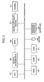
Fig. 3 is a block diagram illustrating the hardware configuration of the marker position-and-orientation estimating device according to the first example. -
Fig. 4A is a diagram illustrating a point marker employed in the first example. -
Fig. 4B is a diagram illustrating a plane marker employed in the first example. -
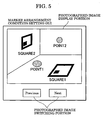
Fig. 5 is a diagram illustrating a GUI (Graphical User Interface) for setting multiple markers present on the same plane. -
Fig. 6 is a diagram illustrating a camera coordinate system and an image coordinate system. -
Fig. 7 is a diagram illustrating a collinear condition equation. -
Fig. 8 is a diagram illustrating a plane definition method. -
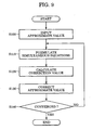
Fig. 9 is a flowchart illustrating procedures for obtaining the positions of point markers, and the positions and orientations of square markers, according to the first example. -
Fig. 10 is a diagram illustrating a case in which two planes constraining markers exist. -
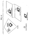
Fig. 11 is a diagram illustrating marker placements to which a preferred embodiment can be applied. -
Fig. 12 is a diagram illustrating marker placements to which a fourth example can be applied. -
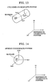
Fig. 13 is a diagram illustrating a marker being constrained on the side face of a cylinder. -
Fig. 14 is a diagram illustrating a marker being constrained on a spherical surface. -
Figs. 15A through 15C are diagrams illustrating a GUI according to the fourth example. - Description is made below regarding exemplary embodiments of the present invention with reference to the appended drawings.
-
Fig. 2 is a block diagram illustrating the functional configuration of a marker position-and-orientation estimating device 2 according to the present example. Animaging unit 210 is a camera, which photographs a scene in which markers are disposed. Animage capturing unit 220 inputs an image photographed by theimaging unit 210 to a computer. A marker detecting-and-identifyingunit 230 detects markers from the image input to the computer from theimage capturing unit 220, and identifies each detected marker. A marker placementcondition setting unit 240 sets a constraint condition regarding placement of markers. A marker position-and-orientation calculating unit 250 calculates the position and orientation of each marker so as to satisfy the constraint condition regarding the position of markers set by the marker placementcondition setting unit 240 based on the marker detection results of the marker detecting-and-identifyingunit 230. -
Fig. 3 is a block diagram illustrating the hardware configuration of the marker position-and-orientation estimating device 2 according to the present example. The hardware configuration illustrated inFig. 3 is the same configuration as that of a common personal computer, but is further connected with animage capturing device 310 and acamera 311. Theimage capturing device 310 is for inputting an image photographed by thecamera 311 to the computer, and corresponds to theimage capturing unit 220. An example of theimage capturing device 310 is a video capturing board, but is not restricted to this as long as an image photographed by a camera can be input. ACPU 301 serves as the marker detecting-and-identifyingunit 230, marker placementcondition setting unit 240, and marker position-orientation calculating unit 250 by executing a program stored in an unshown optical medium, external storage device, or the like. - The hardware configuration of the marker position-and-
orientation estimating device 2 shown inFig. 3 may also include other conventional computer components, such as agraphic accelerator 302 in communication with a head-mounted display (HMD) 304, a storage device, such as adisk 305, a read-only memory (ROM) 306, a random access memory (RAM) 307, and one or more input devices, such as akeyboard 309 and a mouse 308. - Next, description is made regarding the overview of operation of the marker position-and-orientation estimating device according to the present example having the aforementioned configuration.
- First, description is made regarding markers to be employed with the present example.
Figs. 4A and 4B are diagrams illustrating markers to be employed with the present example.Fig. 4A illustrates a point marker in which the placement information is represented by the position of a point in 3-D space. Let us say that point markers have a circular shape having a single color so as to be detected within an image, and the center of gravity of each point marker represents the position thereof in 3-D space.Fig. 4B illustrates a plane marker of which the placement information is represented by the position and orientation of a plane in 3-D space. The present embodiment employs square markers as plane markers, but plane markers are not restricted to square markers, so any shaped markers may be employed as long as markers have a form of a planar shape. Let us say that the center of a square, i.e., the intersecting point of two diagonal lines, represents the position of a square marker in 3-D space. As illustrated inFig. 4B , let us say that the normal line direction of the square marker is taken as the z axis, the coordinate system of the square marker is assigned so that the x axis and y axis can be parallel to the two sides, and the orientation of the coordinate system of the square marker to the reference coordinate system is taken as the orientation of the square marker. The square markers according to the present example are surrounded with a black frame so as to be easily detected on an image, so a square within the black frame is employed as a square marker. - A user photographs many images of a scene in which markers are disposed using the
imaging unit 210. The photographed images are input to the computer by theimage capturing unit 220. - The marker detecting-and-identifying
unit 230 detects markers from the photographed images input to the computer, and performs identification thereof. Here, the term "detection of a marker" means to obtain the image coordinates of a marker on a 2-D image. In the case of point markers, the image coordinates of the center of gravity of marker region on an image are obtained, and, in the case of square markers, the image coordinates of each vertex are obtained. The image coordinates of a marker may be obtained automatically, or may be manually specified, for example, by the user clicking on the image with a mouse. In the case of obtaining the position of a point marker automatically, for example, a pixel having the same color as a marker is extracted based on whether or not the pixel belongs to the specific region of a YUV color space image corresponding to the color, a marker region is obtained by labeling the pixels connected as the same color, and the center of gravity of the marker region within the image is calculated. Also, in the case of obtaining the position of each vertex of a square marker automatically, for example, an input image is converted into binarized image, the black frame region of a square marker is detected, and a quadrangle inscribing the black frame region is obtained. - The term "identification of a marker" means to identify a marker to be detected within an image as a unique marker. Identification of a marker may be performed automatically, or may be performed manually by the user. In the case of identifying a point marker automatically, for example, multiple markers having different colors are employed, and identification is performed based on the labeling color of the marker region at the time of detection of markers. Also, in the case of identifying a square marker automatically, for example, identification is performed by giving a unique pattern to each marker.
- The user sets a constraint condition regarding the placement of markers using the marker placement
condition setting unit 240. With the present example, a constraint condition that multiple markers exist on the same plane is given as a constraint condition regarding the placement of markers. Let us say that a plane employed here is an unknown plane, and multiple unknown planes exist.Fig. 5 illustrates a GUI (Graphical User Interface) for setting multiple markers present on the same plane. A photographed image switching portion exists on the GUI, where an image photographed by the imaging unit is displayed. Display of a photographed image may be switched with a button on the photographed image switching portion. Upon the user clicking a Previous button with the mouse, the previous photographed image is displayed. Upon the user clicking a Next button, the subsequent photographed image is displayed. The user sets markers on the same plane while watching the photographed image. On the photographed image, the name unique to each marker is displayed near each identified marker.Fig. 5 illustrates the case that a photographed image in which two point markers (POINT1 and POINT2 in the drawing) and two square markers (SQUARE1 and SQUARE2 in the drawing) are photographed is displayed on the photographed image display portion. Let us say that of these markers, the point marker POINT1 and the square marker SQUARE1 exist on the same plane. The user selects either POINT1 or SQUARE1 within the photographed image by clicking near either marker with the mouse. The name of the selected marker is changed to bold face. Next, the user forms a group from markers on the same plane by clicking nearby markers present on the same plane with the left mouse button as the selected marker while depressing the shift key. In the case of clicking on a marker belonging to a group present on the same plane, the name display of all of the markers belonging to the group is changed to bold face. In this state, the marker can be added to the group by the user clicking another marker with the left mouse button while depressing the shift key. Also, the user clicking nearby a marker belonging to a group with the right mouse button while depressing the shift key releases the marker from the group, and the user clicking the same marker with the right mouse button without depressing the shift key releases the entire group. - The position and orientation of a marker in the reference coordinate system is calculated based on the detection and identification results of the marker and the constraint condition regarding the placement of markers. First, description is made regarding perspective projection transform.
Fig. 6 is a diagram illustrating the camera coordinate system and the image coordinate system. Let us say that the intersecting point between the viewing axis and an image surface is taken as the origin Oi of the image coordinate system, the horizontal direction of an image is taken as the xi axis, and the vertical direction of the image is taken as the yi axis. Also, let us say that the focal length between the origin Oc of the camera coordinate system and the image surface is f, the zc axis of the camera coordinate system is taken in the opposite direction of the viewing axis, the xc axis is taken in the direction in parallel with the horizontal direction of the image, and the yc axis is taken in the direction in parallel with the vertical direction of the image. - According to perspective projection transform, the point xc = [xc yc zc]t on the camera coordinate system is projected on a point of which the image coordinates are u = [ux uy]t as shown in Expression (2) .

- With the present example, let us say that lens distortion does not exist, or has been corrected, and the camera is a pin-hole camera. As illustrated in
Fig. 7 ,Expression 1 represents that a point in space, the projected point of the point on an image, and a camera position (viewpoint) exist on the same straight line, and is also referred to as a collinear condition. - In the reference coordinate system, let us say that the camera position is t = [tx ty tz]t, and camera orientation (the orientation of the reference coordinate system to the camera coordinate system, in reality) is ω = [ωx ωy ωz] . Note that ω is a 3-degree-of-freedom orientation expression, and orientation is represented with a rotation axial vector and rotation angle. If the rotation angle is ra, then ra is represented with ω as shown in Expression (3).

- Also, if the rotation axial vector is raxis = [rx ry rz]t, the relationship between raxis and ω is represented as shown in Expression (4).

- The relationship between ω (rotation angle ra and rotation axial vector raxis) and 3 × 3 rotational transform matrix R is represented as shown in Expression (5).

- The camera coordinate xc of a point xw = [xw yw zw]t on the reference coordinate system is represented with t and R as shown in Expression (6).

- According to Expressions (2) and (6), i.e., perspective projection transform, the point Xw = [xw yw zw]t on the reference coordinate system is projected on the point u = [uX uy]t on the image as shown in Expression (7).

- Ideally, the projected position (calculated position) calculated from Expression (7) based on t, ω, xw is identical to the position (observation position) to be observed. Accordingly, if we say that the error between the projected position and the observation position in the horizontal direction of the image is F, the error in the vertical direction is G, and the observation position is uo = [uox uoy]t, F and G become zero as shown in Expression (8).

- F and G are functions regarding the camera position t, camera orientation ω, and position xw of the observation target point on the reference coordinates. Here, the position xw of the point on the reference coordinates becomes a different variable function depending on the types of markers, and whether to constrain markers on the plane, so F and G also become a different variable function depending on the types of markers, and whether to constrain markers on the plane. Description is made below by dividing into two cases, i.e., the case of constraining markers on the plane, and the case of not constraining markers on the plane.
- In the case of point markers, if we say that the position of a point marker on the reference coordinate system is tpn = [tpnx tpny tpnz]t, xw is identical with tpn as shown in Expression (9).

- Accordingly, as shown in Expression (10), F and G become functions regarding the camera position t, camera orientation ω, and position tpn of a point marker on the reference coordinate system.

- Next, description is made regarding the case of square markers. Square markers are represented with the position ts = [tsx tsy tsz]t in the reference coordinate system and the orientation ωs = [ωsx ωsy ωsz] as to the reference coordinate system (let us say that 3 × 3 rotational transform matrix corresponding to ωs is Rs). Let us say that the position of vertices of a square marker in the square marker coordinate system is xs = [xs ys O]t. The position xw of the vertices of a square marker in the reference coordinate system becomes a function regarding ts and ωs (Rs) as shown in Expression (11).

- Accordingly, as shown in Expression (12), F and G become functions regarding the camera position t, camera orientation ω, position tp of a square marker, and orientation ωs of a square marker.

- First, description is made regarding a method for defining a plane. As illustrated in
Fig. 8 , the plane is represented with polar coordinate expression r = [r θ ϕ]. The zp axis of the plane coordinate system is parallel to the normal line direction of the plane, and passes through the point of origin in the reference coordinate system. The orientation of the plane is defined with rotation θ around the y axis and rotation ϕ around the x axis. Also, r is a signed distance between the plane and the origin ow of the reference coordinate system. The rotation matrix Rp representing the orientation of the plane is represented as shown in Expression (13).
Note thatn represents the normal line vector of the plane.

- The point marker constrained on the plane is represented with the position tpl p = [tpl px tpl py O]t. As shown in Expression (16), xp is identical with tpl p.

- Accordingly, xw is a function of tpl p and r, and F and G become functions of the camera position t, camera orientation ω, position tpl p of the point marker on the plane, and parameter r of the plane, as in Expression (17).

- On the other hand, in the case of square markers, in addition to the position tpl s = [tpl sx tpl sy O]t on the plane coordinate system, the square marker constrained on the plane is represented with the rotation θpl around the normal line vector of the square marker (i.e., around the zp axis of the plane coordinate system). So, if we say that the position of the vertices of the square marker in the square marker coordinate system is xs = [xs ys O] t, the plane coordinate xp thereof is represented as shown in Expression (18) .

- Thus, xw is a function of tpl s, θpl, and r, and F and G become functions of the camera position t, camera orientation ω, position tpl s of the square marker on the plane, orientation θpl of the square marker on the plane, and parameter r of the plane, as in Expression (19).

- Expressions (10), (12), (17), and (19) are nonlinear expressions regarding the camera position and orientation, position and orientation of the marker, and the plane parameter. Accordingly, linearization is performed in the vicinity of the approximate values regarding the position and orientation of the camera, the position and orientation of the marker, and the plane parameters using the Taylor expansion up to first order, and the position and orientation of the camera, the position and orientation of the marker, and the plane parameters are obtained using repeated calculation.
- Expressions (20), (21), (22), and (23) are obtained by linearizing the corresponding Expressions (10), (12), (17), and (19) respectively. Here, Δtx, Δty, and Δtz represent the correction value for the approximate values of the position of the camera; Δωx, Δωy, and Δωz for the orientation of the camera; Δtpx, Δtpy, and Δtpz for the position of the point marker not constrained to the plane; Δtsx, Δtsy, and Δtsz for the position of the square marker not constrained to the plane; Δωsx, Δωsy, and Δωsz for the orientation of the square marker not constrained to the plane; Δtpl px and Δtpl py for the position on the plane of the point marker constrained to the plane; Δtpl sx and Δtpl sy for the position on the plane of the square marker constrained to the plane; Δθpl for the orientation on the plane of the square marker constrained with the plane; and Δr, Δθ, and Δϕ for the correction value as to the approximate values of the plane parameters.


- Here, F0 and G0 in Expressions (20), (21), (22), and (23) are constants, and represent the difference between the observed position uo and the projected position (calculated position) of the marker obtained from the approximate values regarding the position and orientation of the camera, the position of the point marker or the position and orientation of the square marker, and the plane parameters.
- Expressions (20), (21), (22), and (23) are observation equations regarding one point marker or one vertex of a square marker observed on a certain image. In reality, multiple point markers or multiple square markers are observed on multiple images, so multiple Expressions (20), (21), (22), and (23) are obtained. Accordingly, the positions and orientations of the cameras, the positions of the point markers not constrained on the plane, the positions and orientations of the square markers not constrained on the plane, the positions of the point markers constrained on the plane, the positions and orientations of the square markers constrained on the plane, and the plane parameters are obtained by solving multiple Expressions (20), (21), (22), and (23) as simultaneous equations regarding the correction values as to the approximate values regarding the positions and orientations of the cameras, the positions of the point markers not constrained on the plane, the positions and orientations of the square markers not constrained on the plane, the positions of the point markers constrained on the plane, the positions and orientations of the square markers constrained on the plane, and the plane parameters.
-
Fig. 9 is a flowchart illustrating procedures for obtaining the positions of point markers, and the positions and orientations of square markers according to the present example. Now, let us say that photographing of scenes including markers and extraction and identification of the markers from photographed images have been completed. In Step S100, the approximate values regarding the positions and orientations of the cameras taking each image, the positions of the point markers, the positions and orientations of the square markers, and the plane parameters are set. In the subsequent steps, correction values for correcting the approximate values set in Step S100 are obtained. In Step S110, formulation of simultaneous equations for simultaneously obtaining the correction value of each approximate value is performed so as to minimize the projection error based on the approximate values regarding the positions and orientations of the cameras, the positions of the point markers, the positions and orientations of the square markers, and the plane parameters. In Step S120, the correction value of each approximate value is obtained from the simultaneous equations formulated in Step S110. In Step S130, new approximate values are obtained by correcting each approximate value with the corresponding correction value obtained in Step S120. In Step S140, determination is made as to whether or not the approximate values regarding the positions and orientations of the cameras, the positions of the point markers, the positions and orientations of the square markers, and the plane parameters are converged to the optimized value in Step S130. If so, processing ends. If not, processing returns to Step S110 and steps S110 - S140 are repeated. More specific descriptions regarding each step are provided below. - In Step S100, the approximate values regarding the position and orientation of the camera taking the images, the positions of the point markers, the positions and orientations of the square markers, and the plane parameters are input. Here, let us say that the number of images taken is N, the positions of the camera taking each image are ti =[tixtiytiz]t (i = 1, and so on through N), and the orientations thereof are ωi = [ωix ωiy ωiz] (i = 1, and so on through N). Also, of the point markers of which the positions need to be obtained, let us say that the number of the point markers not constrained on the plane is Kp1, the number of the point markers constrained on the plane is Kp2, and the positions of the respective point markers are tpi = [tpixtpiytpiz] t (i = 1, and so on through Kp1), tp1 pi = [tp1 pix tp1 piy]t (i = 1, and so on through Kp2). Further, of the square markers of which the positions and orientations need to be obtained, let us say that the number of the square markers not constrained on the plane is Ks1, the number of the square markers constrained on the plane is Ks2, and the positions of the respective square markers are tsi = [tsix tsiy tsiz]t (i = 1, and so on through Ks1), tpl si = [tpl six tpl siy]t (i = 1, and so on through Ks2), and the orientations thereof are ωsi = [ωsix ωsiy ωsiz] (i = 1, and so on through Ks1), θpl i (i = 1, and so on through Ks2) .
- The approximate values of the position and orientation of each camera may be obtained from the output value of a 6-degree-of-freedom position and orientation sensor such as a magnetic sensor, which is mounted on the camera, or may be obtained from the correspondence between points of which the positions in the reference coordinate system are known, and the projected position of the point on the image. In the case of employing a point of which the position in the reference coordinate system is known, both the point of which the position is known, and markers of which the positions to be obtained are unknown are mixed in the scene. Alternately, the approximate values of the position and orientation of each camera may be obtained based on the later-described approximate values of the position and orientation of a marker.
- Alternately, the approximate values of the position and orientation of each camera may be obtained mechanically, for example, with a motion control camera, or photographing with a camera of which the position and orientation have been calibrated beforehand may be performed so as to employ the calibration results.
- The approximate values of the position and orientation of each marker may be a rough value measured by hand using a measuring tape, ruler, protractor, or surveying instrument, or may be a value estimated once using the method according to the present example or the like. The approximate values of the position and orientation of each marker constrained on the plane may be the values of the position and orientation of the marker in the plane coordinate system.
- In the event that the markers on the same plane are all point markers, the approximate values of the plane parameters may be obtained by obtaining a regression plane from the approximate value of the position of each point marker. On the other hand, in the event that the markers on the same plane include the square markers, the approximate values of the plane parameters may be obtained from the position and orientation of each square marker by assuming that each square marker is the plane. Further, the user may specify the plane parameters directly without obtaining the plane parameters from the approximate values of the position and orientation of each marker.
- Next, in Step S110, observation equations of Expressions (20), (21), (22), and (23) are formulated of a number corresponding to the number of the markers to be observed on the image. Expressions (20), (21), (22), and (23) are observation equations regarding the correction values of the position and orientation of one camera, the correction value of the position of one point marker or the correction values of the position and orientation of one square marker, and the correction value of one plane parameter. Here, as shown in Expression (24), an observation equation regarding the positions and orientations of N cameras, the positions of Kp1 point markers not constrained on the plane, the positions of Kp2 point markers constrained on the plane, the positions of Ks1 square markers not constrained on the plane, the positions of Ks2 square markers constrained on the plane, and P plane parameters is formulated. In this case, the number of unknown correction values is (6 × N + 3 × Kp1 + 2 × Kp2 + 6 × Ks1 + 3 × Ks2 + 3 × P).

- If we say that the number of point markers to be detected from an image i (i = 1, and so on through N) is dpi, and the number of square markers is dsi, the number Dp of the point markers to be detected from the N images and the number Ds of the square markers to be detected from the N images are represented as shown in Expression (25).

- In the case in which the number of the point markers to be detected from the N images is Dp, and the number of the square markers to be detected from the N images is Ds, (Dp + 4 x Ds) sets of observation equation (24), i.e., 2 x (Dp + 4 x Ds) observation equations are formulated. If simultaneous equations are formulated by transposing the constant terms F0 and G0 on the left side of the Expression (24) to the right side thereof, the simultaneous equations are written in a matrix format as shown in Expression (26).

- J is called a "Jacobian matrix" in which partial differential coefficients regarding the position and orientation of a camera, the position of a point marker, the position and orientation of a square marker, and a plane parameter, of F and G are arrayed. The number of rows of the Jacobian matrix J is the number of the observation equations, i.e., 2 × (Dp + 4 × Ds), the number of columns thereof is the number of unknowns, i.e., (6 × N + 3 × Kp1 + 2 × Kp2 + 6 × Ks1 + 3 × Ks2 + 3 × P). Δ represents a correction vector. The size of the correction vector is the number of unknowns, i.e., (6 × N + 3 × Kp1 + 2 × Kp2 + 6 × Ks1 + 3 × Ks2 + 3 × P). E represents an error vector, and has -F0 and -G0 which are the differences between the calculated position of the projected position due to the approximate value and the observed position. The size of E is the number of the observation equations, i.e., 2 × (Dp + 4 × Ds).
- Note that the origin, scale, and orientation of the reference coordinate system can be clearly specified by photographing point markers of which the positions are known or square markers of which the positions and orientations are known in the reference coordinate system simultaneously. In Expression (24), the partial differential coefficients regarding the positions and orientations of these markers become zero. In order to clearly specify the origin, scale, and orientation of the reference coordinate system, three point markers, of which the positions are known, need to be employed in the case of point markers, or one square marker of which the position and orientation are known needs to be employed in the case of square marker's.
- Next, in Step S120, the correction values as to the approximate values regarding the positions and orientations of the cameras, the positions of the point markers, the positions and orientations of the square markers, and the plane parameters, are obtained using Expression (26). In the case that the Jacobian matrix J is a square matrix, the correction value vector Δ is obtained by multiplying both sides of Expression (26) by the inverse matrix of the matrix J. In the case that the matrix J is not a square matrix, the correction value vector Δ is obtained using the least mean square method, as shown in Expression (27).

- Next, description is made regarding a method for obtaining each factor of the Jacobian matrix J. First, definition is made that F = [F G]t. From Expressions (7) and (8), F and G can be written as shown in Expression (28), so F and G are functions of xc, yc, and zc.

- The Jacobian matrix JFXc of which each factor has a partial differential coefficient according to xc, yc, and zc of F and G, can be written as shown in Expression (29).

- Here, if xc, yc, zc are the functions of variables S1, S2, and so on through Sm, then F and G are also the functions of the variables S1, S2, and so on through Sm. The Jacobian matrix JFS of which each factor has a partial differential coefficient according to S1, S2, and so on through Sm of F and G, can be decomposed as shown in Expression (30).

- The Jacobian matrix JFt of which each factor has a partial differential coefficient according to the camera position tx, ty, and tz of F and G can be written as shown in Expression (31).

- Note that the relationship between the orientation ω and 3 × 3 rotation transform matrix R is as represented in Expression (5).
- The Jacobian matrix JFω of which each factor has a partial differential coefficient according to the camera orientations ωx, ωy, and ωz of F and G can be written in a decomposed manner as shown in Expression (32).

- Here, JXcR is the Jacobian matrix as shown in Expression (33).

- Also, JRraxis is the Jacobian matrix as shown in Expression (34).

- Also, if definition is made that

axis 

- Further, Jωω is the Jacobian matrix as shown in Expression (36).

- The Jacobian matrix JFtP of which each factor has a partial differential coefficient according to the position tpx, tpy, and tpz of the point marker not constrained on the plane of F and G can be written as shown in Expression (37).

- The Jacobian matrix JFt
s of which each factor has a partial differential coefficient according to the position tsx, tsy, and tsz of the square marker not constrained on the plane of F and G can be written as shown in Expression (38).
- The Jacobian matrix JFω
S of which each factor has a partial differential coefficient according to the orientation ωs of the square marker not constrained on the plane of F and G can be broken down as shown in Expression (39) .
s ωs can be obtained in the same way as Expressions (34) through (36). - Next, the Jacobian matrix

c xw can be obtained in the same way as within Expression (38) .
- The Jacobian matrix


- The Jacobian matrix JFθ pl of which each factor has a partial differential coefficient according to the orientation θpl of the square marker constrained on the plane of F and G can be written as shown in Expression (42).

- The Jacobian matrix Jpr of which each factor has a partial differential coefficient according to the plane parameters r, θ, and ϕ of F and G can be written as shown in Expression (43).

- Next, in Step S140, convergence is determined. Determination of convergence is performed by determining a condition, e.g., whether or not the absolute value of the correction value is less than a specified threshold, whether or not the difference between the calculated position of the projected position and the observed position is less than a specified threshold, whether or not the difference between the calculated position of the projected position and the observed position becomes the minimum value, or the like. In the event that determination is made that convergence is satisfied, estimation of the positions and orientations of markers is completed, otherwise, the flow returns to Step S110, where simultaneous equations are formulated again based on the corrected approximate values regarding the positions and orientations of the cameras, the positions of the point markers, the positions and orientations of the square markers, and the plane parameters.
- As described above, with the present example, a great number of images of the scene in which markers are disposed are photographed, the markers are detected and identified from the photographed images, the multiple markers present on the same plane are specified, correction values corresponding to the approximate values regarding the positions and orientations of the cameras taking the images, the positions and orientations of the markers not constrained on the plane, the positions and orientations of the markers constrained on the plane, and the plane parameters, are obtained based on the marker observed positions on the images and the constraint condition that the markers are present on the same plane, and then the approximate values are corrected with the obtained correction values. This operating cycle for obtaining correction values corresponding to the approximate values and correcting the approximate values with the obtained correction values is repeated, thus obtaining the positions and orientations of the markers so as to satisfy the constraint condition.
- Note that with the present example, the plane parameters are all unknown, but the present invention is not restricted to this; i.e., the plane parameters may be known. For example, in the event that the plane parameters can be easily obtained, such as the case of the x-y plane in the reference coordinate system, the plane parameters may be known. In the event that the plane parameters are known, the observation equation of the point markers constrained on the plane in Expression (22) is represented as shown in Expression (44).

- Also, the observation equation of the square markers constrained on the plane in Expression (23) is represented as shown in Expression (45).

- As described above, according to the present example, in the event that there is a constraint condition regarding the placements of markers, the positions and orientations of markers can be obtained accurately by obtaining the positions and orientations of the markers so as to satisfy the constraint condition.
- With the first example, in the event that the constraint condition that multiple markers are present on the same plane is given as a constraint condition regarding the placements of markers, a method for estimating the positions and orientations of markers so as to satisfy the constraint condition has been described. With the second embodiment, description will be made regarding the case in which multiple markers are present on multiple planes, and the angle between the planes is known.
- Note that description will be made here regarding the case in which two planes exist, and the angle between the two planes is known, but the number of planes is not restricted to two.
-
Fig. 10 illustrates the case in which two planes constraining markers exist. As described in the first example, aplane 1 is represented with a polar coordinate expression r1 = [r1 θ1 φ1] in the reference coordinate system. - On the other hand, a
plane 2 is also represented with a polar coordinate expression r2 = [r2 θ2 φ2], and let us say that θ2 and φ2 represent the orientation relative to theplane 1. More specifically, let us say that the orientation obtained when theplane 1 is rotated around the ypl axis by θ2, and then rotated around the xpl axis by φ2 is the orientation of aplane 2. Also, r2 is the signed distance between the origin in the reference coordinate system and theplane 2. At this time, rotation matrixes Rp1 and Rp2 representing the orientations of theplane 1 andplane 2 can be written as shown in Expressions (47) and (48) respectively.


- Here, φ2 can be obtained with θ2 and α from Expression (49).
- The observation equations of point markers and square markers constrained on the
plane 1 are the same as Expressions (22) and (23) according to the first example. On the other hand, theplane 2 becomes the functions of r2 and θ2, so the observation equations of point markers and square markers constrained on theplane 2 are represented as shown in Expression (50) and Expression (51), respectively.

- With the present example, in the event of obtaining the positions and orientations of markers, simultaneous equations are formulated based on observation equations (22), (23), (50), and (51), correction values as to the approximate values regarding the positions and orientations of the cameras, the positions and orientations of the markers, the three parameters of the
plane 1, and the two parameters of theplane 2 are obtained, and the approximate values are optimized using repeated calculation. Note that in the event of obtaining φ2 from Expression (49), two solutions having a different sign are obtained, but of these two solutions of φ2, the one solution reducing projection error as to θ2 obtained for each repeated calculation more than the other is employed as the solution. - As described above, with the present example, in the case in which multiple markers are present on multiple planes as a constraint condition regarding the placements of markers, and also the angle between these planes is known, the positions and orientations of the markers can be obtained so as to satisfy the constraint condition.
- With the preferred embodiment, description will be made regarding a method for estimating the positions and orientations of markers in the case in which the normal vector directions of markers are the same, such as multiple plane markers, as a constraint condition regarding the placements of markers.
-
Fig. 11 is a diagram illustrating marker placements to which the preferred embodiment can be applied. In the drawing, let us say that four square markers are disposed, and the normal vectors of the four square markers, i.e., the direction of the zs axis of each square marker is the same. - The normal vector directions of the square markers will be represented with θ and φ. Let us say that the normal vector is a vector obtained by the unit vector of the z axis in the reference coordinate system being rotated around the x axis by θ, and then being rotated around the y axis by φ. Also, θ and φ have the common value for the multiple square markers having the same normal vector direction. If we say that the rotation around the z axis of each square marker is ψ, the orientation Rs of the square marker as to the reference coordinate system is represented with Expression (52).

- If we say that the position of each square marker in the reference coordinate system is ts = [tsx tsy tsz]t, the position xw in the reference coordinate system of the point xs = [xs ys]t on the square marker is represented with Expression (53).

- With the present embodiment, the position in the reference coordinate system of each vertex of each square marker forms the function of the normal vector directions θ and φ, z-axial orientation of the square markers ψ, and the position ts in the reference coordinate system of each square marker. Accordingly, the observation equation of each vertex of a square marker of which the normal vector being constrained is represented with Expression (54).

- With the present embodiment, in the event of obtaining the positions and orientations of markers, simultaneous equations are formulated based on the multiple observation equations (54), correction values as to the approximate values regarding the positions and orientations of the cameras, the positions and orientations of markers, and the normal vector directions θ and φ are obtained, and then the approximate values are optimized using repeated calculation.
- As described above, with the present embodiment, in the event of multiple markers having the common normal vector direction as a constraint condition regarding the placements of markers, the positions and orientations of the markers can be obtained so as to satisfy the constraint condition.
- With the first and second example and with the preferred embodiment the positions and orientations of markers have been obtained under one constraint condition regarding the placements of markers. With the fourth example, a method for obtaining the positions and orientations of markers under multiple constraint conditions will be described.
-
Fig. 12 is a diagram illustrating marker placements to which the present example can be applied. The drawing illustrates the case in which apoint marker 1 and asquare marker 1 exist on the same plane (plane 1), asquare marker 2 and asquare marker 3 have the common normal vector direction, and apoint marker 2 and asquare marker 4 have no constraint conditions regarding placement thereof. - Upon the scene illustrated in
Fig. 12 being photographed with an imaging device, observation equation (22) holds for thepoint marker 1, observation equation (23) for thesquare marker 1, observation equation (54) for thesquare markers point marker 2, and observation equation (21) for thesquare marker 4. Expressions (20) through (23) and (54) are observation equations regarding the correction value of the position and orientation of one camera, the correction value of the position and orientation of one marker, the correction value of one plane parameter, and the correction value of one normal vector direction. With the present example, as shown in Expression (55), observation equations are formulated regarding the correction values of the positions and orientations of N cameras, the correction values of the positions of Kp1 point markers not constrained on the plane, the correction values of the positions of Kp2 point markers constrained on the plane, the correction values of the positions and orientations of Ks1 square markers not constrained on the plane, the correction values of the positions and orientations of Ks2 square markers constrained on the plane, the correction values of the positions and orientations of Ks3 square markers of which the normal vectors are constrained, the correction values of P plane parameters, and the correction values of V normal vector directions.
- Expression (55) serving as an observation equation is formulated for each point marker, and each vertex of each square marker detected on the photographed images, and is solved as simultaneous equations, thus simultaneously obtaining correction values corresponding to the approximate values regarding a camera position ti, camera orientation ωi, placement-unconstrained point marker position tpi, placement-unconstrained square marker position tsi, orientation ωsi, on-plane-constrained point marker position tplpi, on-plane-constrained square marker position tpl si, orientation θpl i, normal-vector-constrained square marker position tv si, orientation ψi, plane parameter ri, normal vector directions θv i and φv i, and optimizing the approximate values by repeating correction of the approximate values using repeated calculation.
- A GUI (Graphical User Interface) for setting the marker placement conditions according to the present example is illustrated in
Figs. 15A through 15C . With the GUI inFigs. 15A through 15C , grouping of markers, and the constraint condition type of each group can be set. The GUI inFigs. 15A through 15C further include a function for setting a constraint condition type in addition to the GUI inFig. 5 . Upon the user clicking near the selecting marker (inFig. 15A ) with the right mouse button, a dialog box (Fig. 15B ) for selecting a constraint condition is displayed. Subsequently, the user sets a constraint condition (e.g., plane constraint, normal vector constraint, straight line constraint) as to the selected marker group, using this dialog box. Note that other formats for the user interface may be used, for example, a menu as illustrated inFig. 15C may be employed instead of the dialog box illustrated inFig. 15B . - As described above, with the present example, in the case in which multiple constraint conditions regarding the placements of markers exist, the positions and orientations of markers can be obtained so as to satisfy all of the constraint conditions. Thus, the positions and orientations of the markers can be accurately obtained.
- As illustrated in
Fig. 13 , a marker may be constrained on the side face of a cylinder. With the cylinder, the origin is taken in the center of the cylinder coordinate system, and the cylinder coordinate system is taken as illustrated in the drawing. The orientation of the cylinder is represented with a rotation θ around the x axis and a rotation φ around the y axis. A rotation matrix Rcy1 representing the orientation of the cylinder is represented as shown in Expression (56).
- If we say that the position of the origin of the cylinder in the reference coordinate system is tcyl= [tcyl x tcyl y tcyl z]t, the position xw of a point xcyl = [xcyl ycyl zcyl]t on the cylinder coordinate system in the reference coordinate system is represented as shown in Expression (57).

- Also, a point on the side face of the cylinder is represented with Expression (58) in the cylinder coordinate system, from the rotation angle β around the Zcyl axis, the zcyl coordinate d, and a known cylinder radius rcyl.

- The projected position of the marker constrained on the side face of the cylinder forms a function regarding the position and orientation of the camera, the position and orientation of the cylinder, and the positions β and d of the marker on the cylinder, so the position of the marker constrained on the side face of the cylinder can be obtained by solving the observation equation for obtaining these correction values.
- As illustrated in
Fig. 14 , a marker may be constrained on a surface of a sphere. The sphere coordinate system is taken at the center of the sphere. A sphere has no directionality, and accordingly is represented with only the position as to the reference coordinate system. If we say that the position of the origin of the sphere coordinate system in the reference coordinate system is tsph = [tsph xtsph ytsph z]t, the position xw of a point Xsph = [xsphysphzsph]t on the sphere coordinate system in the reference coordinate system is represented as shown in Expression (59).
- Also, a point on the surface of the sphere having a known radius rsph and angles θ and φ is represented with Expression (60) in the sphere coordinate system.

- The projected position of the marker constrained on the sphere surface forms a function regarding the position and orientation of the camera, the position of the sphere, and the positions θ and φ of the marker on the sphere surface, so the position of the marker constrained on the sphere surface can be obtained by solving the observation equation for obtaining these correction values.
- A marker may be constrained on a straight line. If we say that a point where the straight line passes through is t1 = [t1x t1y t1z]t, and a directional vector is d = [dx dy dz]t, the position of the marker present on the straight line in the reference coordinate system is represented with Expression (61). Here, s is a variable representing the marker position on the straight line.

- The projected position of the marker constrained on the straight line forms a function regarding the position and orientation of the camera, the point t1 where the straight line passes through, the directional vector d of the straight line, and the position s of the marker on the straight line, so the position of the marker constrained on the straight line can be obtained by solving the observation equation for obtaining these correction values.
- With the aforementioned embodiment and examples, a method for subjecting observation equations to Taylor expansion, and repeating correction utilizing as far as primary items has been described as a method for correcting marker placement information. This is a method for estimating the amount of correction of unknown parameters in the case of assuming that observation equations are subjected to linearization locally in one process of repetition, and result in no error, and is a method equivalent to a method generally known as the Newton method. The Newton method is a typical method for solving a nonlinear equation using numerical computation, but a repeated calculation method used for the aforementioned embodiment and examples is not restricted to this. For example, the amount of correction may be dynamically changed based on the variance of the amount of correction of an unknown parameter to be estimated in one process, such as with the similarly-known Levenberg-Marquardt method. Alternately, a method for performing repeated calculation in light of the results of Taylor expansion including higher order terms may be employed. The essence of the present invention is obtaining the most appropriate solution using various types of markers even in the event that multiple types of markers having different placement information are mixed, and accordingly, specific methodology for repeated calculation serving as a numerical solution never detracts from the essence of the present invention.
- While the present invention has been described with reference to a preferred embodiment, it is to be understood that the invention is not limited to the disclosed embodiment. On the contrary, the invention is intended to cover various modifications and equivalent arrangements included within the scope of the appended claims.
- The scope of the following claims is to be accorded the broadest interpretation so as to encompass all such modifications and equivalent structures and functions.
Claims (10)
- A marker placement information estimating method for estimating position and orientation information of markers from photographed images, said method comprising:a constraint condition setting step for setting a constraint condition that is defined with a geometric condition relating to position and orientation information of markers;a capturing step for capturing photographed images of a scene including marker images;a marker detecting step for detecting markers on said photographed images;a calculating step for calculating 3D positions of said markers and 2D positions of said markers projected on the photographed images; andan estimating step for estimating the position and orientation information of said markers by solving simultaneous equations representing errors between the detected positions and the calculated projected positions of said markers, wherein the simultaneous equations include the positions and orientations of the markers as unknown parameters and satisfy said constraint condition;wherein said constraint condition is represented by an equation representing the constraint condition, and the position and orientation information satisfying said constraint condition is represented by a set of placement information parameters satisfying said constraint condition;wherein markers present within the scene space are markers of which the normal line vector can be defined, andwherein said constraint condition is a constraint condition that the directions of the normal line vectors of a plurality of markers are the same, the equation representing said constraint condition is a normal line vector equation, and said set of placement information parameters comprise a rotation angle and the normal line vector.
- The marker placement information estimating method according to Claim 1, wherein the constraint condition is set according to user instructions in said setting step, wherein said user instructions include grouping of markers, and the grouping of markers is constrained on the constraint condition whilst the other markers are not so constrained.
- The marker placement information estimating method according to Claim 2, wherein said user instructions include types of constraint condition.
- A program which when loaded into a computer and executed performs a method as claimed in any preceding claim.
- A recording medium storing a program according to Claim 4.
- A marker placement information estimating device (2) for estimating the position and orientation information of markers from photographed images, said device comprising:a constraint condition setting means (240) for setting a constraint condition that is defined with a geometric condition relating to the position and orientation information of markers;a capturing means (210, 220) for capturing photographed images of a scene including marker images;a marker detecting means (230) for detecting markers on said photographed images;calculation means (250) operable to calculate 3D positions of said markers and 2D positions of said markers projected on the photographed images; andan estimating means (250) for estimating the position and orientation information of said markers by solving simultaneous equations representing errors between the detected positions and the calculated projected positions of said markers, wherein the simultaneous equations include the positions and orientations of the markers as unknown parameters and satisfy said constraint condition;wherein said constraint condition is represented by an equation representing the constraint condition, and the position and orientation information satisfying said constraint condition is represented by a set of placement information parameters satisfying said constraint condition;wherein markers present within the scene space are markers of which the normal line vector can be defined, andwherein said constraint condition is a constraint condition that the directions of the normal line vectors of a plurality of markers are the same, the equation representing said constraint condition is a normal line vector equation, and said set of placement information parameters comprise a rotation angle and the normal line vector.
- The marker placement information estimating device according to Claim 6, further comprising:marker projected position calculating means for calculating the position where a marker is projected on an image surface based on the approximate value of the position and orientation of an imaging unit of said photographed image and the approximate value of the placement information of the marker;correction value calculating means for obtaining a correction value for correcting the position and orientation information of a marker so as to reduce a margin of error between the position of the marker on the image surface detected by said marker detecting means and the projected position of the marker on the image surface obtained by said marker projected position calculating means, and also so as to satisfy the constraint condition of markers set by said constraint condition setting means;placement information correcting means for correcting the position and orientation information of a marker based on the correction value obtained by said correction value calculating means; andrepeated calculating means for calculating the position and orientation information of a marker by repeatedly performing execution of said marker projected position calculating means, said correction value calculating means, and said placement information correcting means using the position and orientation information of the marker corrected by said placement information correcting means instead of an approximate value of said marker projected position calculating means.
- The marker placement information estimating device according to Claim 6, wherein said constraint condition is a constraint condition that markers exist on the same unknown plane, the equation representing said constraint condition is a plane equation, and said set of placement information parameters comprise a rotation angle around the normal line vector of the plane and a position on the plane.
- The marker placement information estimating device according to Claim 6, wherein said markers are square shapes.
- The marker placement information estimating device according to Claim 6, wherein there are a plurality of said constraint conditions, and the position and orientation information of said marker is estimated by obtaining the equation representing each constraint condition and the placement information parameter of said marker regarding said plurality of constraint conditions.
Applications Claiming Priority (2)
| Application Number | Priority Date | Filing Date | Title |
|---|---|---|---|
| JP2004144891 | 2004-05-14 | ||
| JP2004144891A JP4522140B2 (en) | 2004-05-14 | 2004-05-14 | Index placement information estimation method and information processing apparatus |
Publications (3)
| Publication Number | Publication Date |
|---|---|
| EP1596329A2 EP1596329A2 (en) | 2005-11-16 |
| EP1596329A3 EP1596329A3 (en) | 2006-02-22 |
| EP1596329B1 true EP1596329B1 (en) | 2010-09-08 |
Family
ID=34941235
Family Applications (1)
| Application Number | Title | Priority Date | Filing Date |
|---|---|---|---|
| EP05252877A Not-in-force EP1596329B1 (en) | 2004-05-14 | 2005-05-11 | Marker placement information estimating method and information processing device |
Country Status (5)
| Country | Link |
|---|---|
| US (1) | US7657065B2 (en) |
| EP (1) | EP1596329B1 (en) |
| JP (1) | JP4522140B2 (en) |
| CN (1) | CN100338632C (en) |
| DE (1) | DE602005023374D1 (en) |
Families Citing this family (51)
| Publication number | Priority date | Publication date | Assignee | Title |
|---|---|---|---|---|
| JP4914019B2 (en) * | 2005-04-06 | 2012-04-11 | キヤノン株式会社 | Position and orientation measurement method and apparatus |
| WO2007004521A1 (en) * | 2005-06-30 | 2007-01-11 | Olympus Corporation | Marker specification device and marker specification method |
| US7656425B2 (en) * | 2006-03-31 | 2010-02-02 | Mitutoyo Corporation | Robust field of view distortion calibration |
| JP4958497B2 (en) * | 2006-08-07 | 2012-06-20 | キヤノン株式会社 | Position / orientation measuring apparatus, position / orientation measuring method, mixed reality presentation system, computer program, and storage medium |
| JP4926817B2 (en) * | 2006-08-11 | 2012-05-09 | キヤノン株式会社 | Index arrangement information measuring apparatus and method |
| WO2008036354A1 (en) | 2006-09-19 | 2008-03-27 | Braintech Canada, Inc. | System and method of determining object pose |
| JP4810403B2 (en) * | 2006-11-08 | 2011-11-09 | キヤノン株式会社 | Information processing apparatus and information processing method |
| KR100906974B1 (en) * | 2006-12-08 | 2009-07-08 | 한국전자통신연구원 | Apparatus and method for reconizing a position using a camera |
| US20080181485A1 (en) * | 2006-12-15 | 2008-07-31 | Beis Jeffrey S | System and method of identifying objects |
| JP4886560B2 (en) * | 2007-03-15 | 2012-02-29 | キヤノン株式会社 | Information processing apparatus and information processing method |
| JP5196825B2 (en) * | 2007-03-29 | 2013-05-15 | キヤノン株式会社 | Image processing apparatus and image processing method |
| US20080266323A1 (en) * | 2007-04-25 | 2008-10-30 | Board Of Trustees Of Michigan State University | Augmented reality user interaction system |
| US20080306708A1 (en) * | 2007-06-05 | 2008-12-11 | Raydon Corporation | System and method for orientation and location calibration for image sensors |
| KR100903629B1 (en) | 2007-07-03 | 2009-06-18 | 주식회사 에이알맥스 | Method for measuring 3D information of object in single image using collinearity condition equation, Recorded Medium for performing the same and System for measuring 3D information of object in single image using collinearity condition equation |
| US7957583B2 (en) * | 2007-08-02 | 2011-06-07 | Roboticvisiontech Llc | System and method of three-dimensional pose estimation |
| US9058764B1 (en) * | 2007-11-30 | 2015-06-16 | Sprint Communications Company L.P. | Markers to implement augmented reality |
| US8542906B1 (en) | 2008-05-21 | 2013-09-24 | Sprint Communications Company L.P. | Augmented reality image offset and overlay |
| KR101465668B1 (en) * | 2008-06-24 | 2014-11-26 | 삼성전자주식회사 | Terminal and method for blogging thereof |
| JP2010025759A (en) * | 2008-07-18 | 2010-02-04 | Fuji Xerox Co Ltd | Position measuring system |
| US8559699B2 (en) * | 2008-10-10 | 2013-10-15 | Roboticvisiontech Llc | Methods and apparatus to facilitate operations in image based systems |
| US8155387B2 (en) * | 2008-10-13 | 2012-04-10 | International Business Machines Corporation | Method and system for position determination using image deformation |
| KR101128913B1 (en) * | 2009-05-07 | 2012-03-27 | 에스엔유 프리시젼 주식회사 | Vision inspection system and method for converting coordinates using the same |
| KR101082285B1 (en) * | 2010-01-29 | 2011-11-09 | 주식회사 팬택 | Terminal and method for providing augmented reality |
| WO2011111122A1 (en) * | 2010-03-12 | 2011-09-15 | 富士通株式会社 | Installation work supporting device, method therefor, and program |
| EP2547278B2 (en) | 2010-03-17 | 2019-10-23 | Brainlab AG | Flow control in computer-assisted surgery based on marker positions |
| US9158777B2 (en) | 2010-03-30 | 2015-10-13 | Gravity Jack, Inc. | Augmented reality methods and apparatus |
| CN101872470B (en) * | 2010-05-30 | 2011-12-28 | 李滨 | Correction and target point positioning method of CT or MRI image |
| WO2012049795A1 (en) * | 2010-10-12 | 2012-04-19 | パナソニック株式会社 | Display processing device, display method and program |
| KR101295712B1 (en) * | 2010-11-22 | 2013-08-16 | 주식회사 팬택 | Apparatus and Method for Providing Augmented Reality User Interface |
| KR101269773B1 (en) * | 2010-12-13 | 2013-05-30 | 주식회사 팬택 | Terminal and method for providing augmented reality |
| US8937628B2 (en) | 2011-06-21 | 2015-01-20 | Siemens Energy, Inc. | Mapping of a contour shape to an X and Y coordinate system |
| JP5988563B2 (en) * | 2011-10-25 | 2016-09-07 | キヤノン株式会社 | Image processing apparatus, image processing apparatus control method and program, information processing apparatus and information processing apparatus control method, and program |
| KR101874895B1 (en) * | 2012-01-12 | 2018-07-06 | 삼성전자 주식회사 | Method for providing augmented reality and terminal supporting the same |
| US8922589B2 (en) | 2013-04-07 | 2014-12-30 | Laor Consulting Llc | Augmented reality apparatus |
| US9191620B1 (en) | 2013-12-20 | 2015-11-17 | Sprint Communications Company L.P. | Voice call using augmented reality |
| JP6425312B2 (en) * | 2014-04-22 | 2018-11-21 | 日本電信電話株式会社 | Dynamic illusion presentation device, method thereof, program |
| US9508195B2 (en) * | 2014-09-03 | 2016-11-29 | Microsoft Technology Licensing, Llc | Management of content in a 3D holographic environment |
| US9734634B1 (en) * | 2014-09-26 | 2017-08-15 | A9.Com, Inc. | Augmented reality product preview |
| JP6564622B2 (en) * | 2015-06-04 | 2019-08-21 | 株式会社大林組 | 3D position measurement method, surveying method, 3D position measurement apparatus, and 3D position measurement program |
| US10424117B2 (en) * | 2015-12-02 | 2019-09-24 | Seiko Epson Corporation | Controlling a display of a head-mounted display device |
| WO2017110071A1 (en) * | 2015-12-25 | 2017-06-29 | パナソニックIpマネジメント株式会社 | Size measurement device, delivery box apparatus, and size measurement method |
| US10072934B2 (en) | 2016-01-15 | 2018-09-11 | Abl Ip Holding Llc | Passive marking on light fixture detected for position estimation |
| JP6688088B2 (en) * | 2016-01-19 | 2020-04-28 | キヤノン株式会社 | Information processing apparatus and control method thereof |
| JP6166409B1 (en) * | 2016-03-16 | 2017-07-19 | ヤフー株式会社 | Image processing apparatus, image processing method, and image processing program |
| US20180268614A1 (en) * | 2017-03-16 | 2018-09-20 | General Electric Company | Systems and methods for aligning pmi object on a model |
| CN108596105B (en) * | 2018-04-26 | 2023-02-03 | 李辰 | Augmented reality painting and calligraphy system |
| US11600022B2 (en) | 2020-08-28 | 2023-03-07 | Unity Technologies Sf | Motion capture calibration using drones |
| US11636621B2 (en) | 2020-08-28 | 2023-04-25 | Unity Technologies Sf | Motion capture calibration using cameras and drones |
| EP4205377A1 (en) * | 2020-08-28 | 2023-07-05 | Weta Digital Limited | Motion capture calibration using drones |
| US11830219B2 (en) * | 2021-12-29 | 2023-11-28 | Midea Group Co., Ltd. | Joint visual localization and orientation detection method |
| JP2023159484A (en) | 2022-04-20 | 2023-11-01 | キヤノン株式会社 | Information processing apparatus, information processing system, control method for information processing apparatus, and program |
Family Cites Families (22)
| Publication number | Priority date | Publication date | Assignee | Title |
|---|---|---|---|---|
| US6268862B1 (en) * | 1996-03-08 | 2001-07-31 | Canon Kabushiki Kaisha | Three dimensional virtual space generation by fusing images |
| US5889550A (en) * | 1996-06-10 | 1999-03-30 | Adaptive Optics Associates, Inc. | Camera tracking system |
| JPH10222668A (en) * | 1997-02-04 | 1998-08-21 | Syst Sakomu:Kk | Motion capture method and system therefor |
| JPH1184307A (en) | 1997-09-01 | 1999-03-26 | M R Syst Kenkyusho:Kk | Head-mounted optical device |
| US6137491A (en) * | 1998-06-05 | 2000-10-24 | Microsoft Corporation | Method and apparatus for reconstructing geometry using geometrically constrained structure from motion with points on planes |
| JP3976900B2 (en) * | 1998-07-23 | 2007-09-19 | キヤノン株式会社 | Method for determining viewpoint position and orientation and camera device |
| US7084887B1 (en) * | 1999-06-11 | 2006-08-01 | Canon Kabushiki Kaisha | Marker layout method, mixed reality apparatus, and mixed reality space image generation method |
| JP4573977B2 (en) * | 1999-09-22 | 2010-11-04 | 富士重工業株式会社 | Distance correction device for monitoring system and vanishing point correction device for monitoring system |
| JP3467017B2 (en) * | 2000-11-30 | 2003-11-17 | キヤノン株式会社 | Position and orientation determination method and apparatus, and storage medium |
| JP3631151B2 (en) * | 2000-11-30 | 2005-03-23 | キヤノン株式会社 | Information processing apparatus, mixed reality presentation apparatus and method, and storage medium |
| GB2372656A (en) * | 2001-02-23 | 2002-08-28 | Ind Control Systems Ltd | Optical position determination |
| US7379077B2 (en) * | 2001-08-23 | 2008-05-27 | Siemens Corporate Research, Inc. | Augmented and virtual reality guided instrument positioning using along-the-line-of-sight alignment |
| US7274380B2 (en) * | 2001-10-04 | 2007-09-25 | Siemens Corporate Research, Inc. | Augmented reality system |
| JP3796449B2 (en) * | 2002-01-31 | 2006-07-12 | キヤノン株式会社 | Position and orientation determination method and apparatus, and computer program |
| EP1349114A3 (en) * | 2002-03-19 | 2011-06-15 | Canon Kabushiki Kaisha | Sensor calibration apparatus, sensor calibration method, program, storage medium, information processing method, and information processing apparatus |
| ES2225680T3 (en) * | 2002-04-16 | 2005-03-16 | Brainlab Ag | MARKER FOR AN INSTRUMENT AND PROCEDURE FOR THE LOCATION OF A MARKER. |
| US7190331B2 (en) * | 2002-06-06 | 2007-03-13 | Siemens Corporate Research, Inc. | System and method for measuring the registration accuracy of an augmented reality system |
| JP3944019B2 (en) * | 2002-07-31 | 2007-07-11 | キヤノン株式会社 | Information processing apparatus and method |
| JP2004151085A (en) * | 2002-09-27 | 2004-05-27 | Canon Inc | Method and apparatus for processing information |
| JP4136859B2 (en) * | 2003-01-10 | 2008-08-20 | キヤノン株式会社 | Position and orientation measurement method |
| JP4532982B2 (en) * | 2004-05-14 | 2010-08-25 | キヤノン株式会社 | Arrangement information estimation method and information processing apparatus |
| US7734084B2 (en) * | 2006-10-20 | 2010-06-08 | Hewlett-Packard Development Company, L.P. | Method and system for offset estimation and alignment |
-
2004
- 2004-05-14 JP JP2004144891A patent/JP4522140B2/en not_active Expired - Fee Related
-
2005
- 2005-05-11 EP EP05252877A patent/EP1596329B1/en not_active Not-in-force
- 2005-05-11 US US11/126,916 patent/US7657065B2/en not_active Expired - Fee Related
- 2005-05-11 DE DE602005023374T patent/DE602005023374D1/en active Active
- 2005-05-16 CN CNB200510068067XA patent/CN100338632C/en not_active Expired - Fee Related
Non-Patent Citations (1)
| Title |
|---|
| BARATOFF G ET AL: "Interactive multi-marker calibration for augmented reality applications", MIXED AND AUGMENTED REALITY, 2002. ISMAR 2002. PROCEEDINGS. INTERNATIO NAL SYMPOSIUM ON SEPT. 30 - OCT. 1, 2002, PISCATAWAY, NJ, USA,IEEE, 30 September 2002 (2002-09-30), pages 107 - 116, XP010620947, ISBN: 978-0-7695-1781-0 * |
Also Published As
| Publication number | Publication date |
|---|---|
| EP1596329A3 (en) | 2006-02-22 |
| CN100338632C (en) | 2007-09-19 |
| EP1596329A2 (en) | 2005-11-16 |
| US7657065B2 (en) | 2010-02-02 |
| US20050253870A1 (en) | 2005-11-17 |
| DE602005023374D1 (en) | 2010-10-21 |
| JP4522140B2 (en) | 2010-08-11 |
| CN1696605A (en) | 2005-11-16 |
| JP2005327103A (en) | 2005-11-24 |
Similar Documents
| Publication | Publication Date | Title |
|---|---|---|
| EP1596329B1 (en) | Marker placement information estimating method and information processing device | |
| US7529387B2 (en) | Placement information estimating method and information processing device | |
| US7664341B2 (en) | Index layout measurement method, position and orientation estimation method, index layout measurement apparatus, and position and orientation estimation apparatus | |
| US8019114B2 (en) | Position and orientation measurement method and apparatus | |
| JP4757142B2 (en) | Imaging environment calibration method and information processing apparatus | |
| JP4137078B2 (en) | Mixed reality information generating apparatus and method | |
| US7397481B2 (en) | Image display method and image display system | |
| US7130754B2 (en) | Sensor calibration apparatus, sensor calibration method, program, storage medium, information processing method, and information processing apparatus | |
| US7928977B2 (en) | Image compositing method and apparatus for superimposing a computer graphics image on an actually-sensed image | |
| JP5248806B2 (en) | Information processing apparatus and information processing method | |
| JP4708752B2 (en) | Information processing method and apparatus | |
| US20040176925A1 (en) | Position/orientation measurement method, and position/orientation measurement apparatus | |
| JP2008065807A (en) | Marker arrangement information measurement unit and method | |
| JP2005326282A (en) | Position and attitude measurement method and system | |
| JP2007233971A (en) | Image compositing method and device | |
| JP2007048068A (en) | Information processing method and device | |
| JP4926598B2 (en) | Information processing method and information processing apparatus | |
| JP4810403B2 (en) | Information processing apparatus and information processing method | |
| JP2014215821A (en) | Information processing apparatus, information processing method and program |
Legal Events
| Date | Code | Title | Description |
|---|---|---|---|
| PUAI | Public reference made under article 153(3) epc to a published international application that has entered the european phase |
Free format text: ORIGINAL CODE: 0009012 |
|
| AK | Designated contracting states |
Kind code of ref document: A2 Designated state(s): AT BE BG CH CY CZ DE DK EE ES FI FR GB GR HU IE IS IT LI LT LU MC NL PL PT RO SE SI SK TR |
|
| AX | Request for extension of the european patent |
Extension state: AL BA HR LV MK YU |
|
| PUAL | Search report despatched |
Free format text: ORIGINAL CODE: 0009013 |
|
| AK | Designated contracting states |
Kind code of ref document: A3 Designated state(s): AT BE BG CH CY CZ DE DK EE ES FI FR GB GR HU IE IS IT LI LT LU MC NL PL PT RO SE SI SK TR |
|
| AX | Request for extension of the european patent |
Extension state: AL BA HR LV MK YU |
|
| 17P | Request for examination filed |
Effective date: 20060822 |
|
| AKX | Designation fees paid |
Designated state(s): DE FR GB IT NL |
|
| 17Q | First examination report despatched |
Effective date: 20061211 |
|
| GRAP | Despatch of communication of intention to grant a patent |
Free format text: ORIGINAL CODE: EPIDOSNIGR1 |
|
| GRAS | Grant fee paid |
Free format text: ORIGINAL CODE: EPIDOSNIGR3 |
|
| GRAA | (expected) grant |
Free format text: ORIGINAL CODE: 0009210 |
|
| AK | Designated contracting states |
Kind code of ref document: B1 Designated state(s): DE FR GB IT NL |
|
| REG | Reference to a national code |
Ref country code: GB Ref legal event code: FG4D |
|
| REF | Corresponds to: |
Ref document number: 602005023374 Country of ref document: DE Date of ref document: 20101021 Kind code of ref document: P |
|
| REG | Reference to a national code |
Ref country code: NL Ref legal event code: VDEP Effective date: 20100908 |
|
| PG25 | Lapsed in a contracting state [announced via postgrant information from national office to epo] |
Ref country code: NL Free format text: LAPSE BECAUSE OF FAILURE TO SUBMIT A TRANSLATION OF THE DESCRIPTION OR TO PAY THE FEE WITHIN THE PRESCRIBED TIME-LIMIT Effective date: 20100908 |
|
| PG25 | Lapsed in a contracting state [announced via postgrant information from national office to epo] |
Ref country code: IT Free format text: LAPSE BECAUSE OF FAILURE TO SUBMIT A TRANSLATION OF THE DESCRIPTION OR TO PAY THE FEE WITHIN THE PRESCRIBED TIME-LIMIT Effective date: 20100908 |
|
| PLBE | No opposition filed within time limit |
Free format text: ORIGINAL CODE: 0009261 |
|
| STAA | Information on the status of an ep patent application or granted ep patent |
Free format text: STATUS: NO OPPOSITION FILED WITHIN TIME LIMIT |
|
| 26N | No opposition filed |
Effective date: 20110609 |
|
| REG | Reference to a national code |
Ref country code: DE Ref legal event code: R097 Ref document number: 602005023374 Country of ref document: DE Effective date: 20110609 |
|
| REG | Reference to a national code |
Ref country code: FR Ref legal event code: PLFP Year of fee payment: 12 |
|
| REG | Reference to a national code |
Ref country code: FR Ref legal event code: PLFP Year of fee payment: 13 |
|
| PGFP | Annual fee paid to national office [announced via postgrant information from national office to epo] |
Ref country code: FR Payment date: 20170524 Year of fee payment: 13 Ref country code: GB Payment date: 20170517 Year of fee payment: 13 Ref country code: DE Payment date: 20170531 Year of fee payment: 13 |
|
| REG | Reference to a national code |
Ref country code: DE Ref legal event code: R119 Ref document number: 602005023374 Country of ref document: DE |
|
| GBPC | Gb: european patent ceased through non-payment of renewal fee |
Effective date: 20180511 |
|
| PG25 | Lapsed in a contracting state [announced via postgrant information from national office to epo] |
Ref country code: DE Free format text: LAPSE BECAUSE OF NON-PAYMENT OF DUE FEES Effective date: 20181201 Ref country code: GB Free format text: LAPSE BECAUSE OF NON-PAYMENT OF DUE FEES Effective date: 20180511 Ref country code: FR Free format text: LAPSE BECAUSE OF NON-PAYMENT OF DUE FEES Effective date: 20180531 |