EP1595990A1 - Shuttle embroidery machine - Google Patents
Shuttle embroidery machine Download PDFInfo
- Publication number
- EP1595990A1 EP1595990A1 EP04405732A EP04405732A EP1595990A1 EP 1595990 A1 EP1595990 A1 EP 1595990A1 EP 04405732 A EP04405732 A EP 04405732A EP 04405732 A EP04405732 A EP 04405732A EP 1595990 A1 EP1595990 A1 EP 1595990A1
- Authority
- EP
- European Patent Office
- Prior art keywords
- driver
- shuttle
- embroidery
- drive
- embroidery machine
- Prior art date
- Legal status (The legal status is an assumption and is not a legal conclusion. Google has not performed a legal analysis and makes no representation as to the accuracy of the status listed.)
- Granted
Links
Images


Classifications
-
- D—TEXTILES; PAPER
- D05—SEWING; EMBROIDERING; TUFTING
- D05C—EMBROIDERING; TUFTING
- D05C11/00—Devices for guiding, feeding, handling, or treating the threads in embroidering machines; Machine needles; Operating or control mechanisms therefor
- D05C11/18—Shuttles ; Shuttle holders; Shuttle driving arrangements
Definitions
- the invention relates to a shuttle embroidery machine with a driver bar for common movement of boats and with a drive shaft for the driver bar.
- Shuttle embroidery machines operate on the two-thread system, i. with a Needle thread and a shuttle thread, the needle thread at each stitch is swallowed up with the shuttle thread.
- a front with an oehr provided needle transports the needle thread through the fabric on the Back of the fabric, where the thread when returning the needle a Loop forms. Through this loop then the boat, in which the Shuttles thread is included, passed.
- a shuttle embroidery machine contains a large number of arranged in a row embroidery and accordingly many needles and boats. To the float the shuttle serves a driver bar.
- Newer machines like them For example, in EP-A-0 638 681, have a Driver bar, which consists of a hollow profile. For each boat is one lower driver nail and an upper driver nail provided between which the shuttle is arranged. With these driver nails the boat is in the shuttle of the so-called Stöcklis moved up and down.
- EP-A-1 055 761 proposes that the driver bar be made of one Produce aluminum profile. This profile has holes in which Plastic driver nails are used. In addition to other benefits thereby creating a driver device with a relatively low mass, which increases the number of turns up to 600 revolutions per minute allowed.
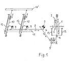
- FIG. 1 which was taken from the cited work, shows this Schiffchenantrieb.
- the cam 1 consists of two parts.
- the two Casters 2 are firmly connected to the slider 3 and move it at Turn the cam up and down. From the bolt 4 is doing the Schiffchenherz 5 offset in a swinging motion.
- the shuttle shaft is running outside the front main machine wall along and has the task to transfer the movement to the back of the machine.
- the angle lever 7 is driven.
- the angle lever 7 converts the oblique up and down movement in a horizontal movement of Driver cable 8 um.
- On this hinges 9 are attached, which have a and cause movement of the guide rods 10.
- a commercially available newer embroidery machine has a shuttle drive on, in which a drive shaft on the rear or Schiffchenseite the Machine extends parallel to the driver bar and at intervals from each other arranged cams to a roller lever parallel to the To pivot drive shaft extending pivot shaft.
- the pivot shaft has at intervals from each other levers, which via rods to the Driver beams are hinged to this with the shuttle up and down move.
- the GB 800 240 published in 1958 describes a sewing machine, which serves with a variety of needles and little boats in small To create distances between parallel seams when the fabric is straight is guided through the machine (Fig. 4, claim 1).
- This document is located
- a problem that is not in shuttle embroidery machines of Meaning is, namely, that the distance between the parallel seams the Size of usable boat limited.
- the construction of the described sewing machine differs significantly from Shuttle embroidery.
- the needles are in two rows distributed over the fabric area.
- the sewing machine thus has no driver bar with linearly arranged over the machine length and drivers powered boats on.
- the boats are in two Rows arranged in cages on a cart, which are driven by a crank and is movable.
- the crank is via a connecting rod to a lever hinged.
- This is in turn via a connecting rod to a Angle lever hinged, which engages the slide bar of the car to to move it back and forth with the boats.
- This Reference is not to be found, as in the case of embroidery machines because of Torsion of a pivot shaft occurring resonant vibrations avoided could become.
- an embroidery machine with a Driver bar or the like for common movement of boat and to provide with a drive shaft for the driver bar the is inexpensive to manufacture and has higher embroidery speeds than previously allowed.
- the embroidery machine according to the invention is characterized in that the Drive shaft arranged over a plurality of spaced apart Crank gear is coupled to the driver bar.
- Cam disc gears are cheap to produce in crank gears. This allowed to dispense with the hitherto necessary pivot shafts and allows it, with relatively low cost in short distances from each other such Provide crank mechanism for the reciprocation of the driver bar. As a result, an impermissible deformation of the driver bar at high Embroidery speeds avoided. Because no pivot shaft more necessary is, also accounts for this pivot shaft inherent torsional and Vibration problems. This allows an increase in the embroidery speed.
- crank gears also run substantially vibration-free and quieter and subject to only minor Wear. By eliminating the pivot shaft is also a Weight savings of the order of several hundred kilos achieved.
- Driver bars are usually provided with guide bars, which in stationary guides are back and forth.
- An advantageous Embodiment of the invention provides that the respective crank gear on such a guide rod or in the immediate vicinity of the guide rod on Driver bar is docked. This will be at the back and forth Deformation of the driver bar by the moving mass of the Guide rods avoided.
- the respective crank mechanism comprises one to the crankshaft articulated connecting rod, a rocker and a rod, the connecting rod to the Rocker, the rocker to the rod and the rod to the driver device is articulated.
- a direct linkage of a connecting rod to the Driver device can by appropriate arrangement and Dimensioning of the mentioned parts a waveform for the Schiffchen Gay be achieved, which is virtually the previously with the Cam achieved waveform corresponds.
- the drive of the drive shaft takes place at both ends thereof.
- the torsion of the drive shaft can be reduced. It is on it but also possible to drive the drive shaft in the middle to the torsion to keep low.
- FIGs 2 to 4 show both the driver device 21 and the for the Driver device 21 provided drive device 23.
- Die Driver device 21 consists essentially of the driver bar 25, which is supported by the guide rods 26.
- the guide rods 26 are stored in guides 27 of the machine frame.
- the drive device has a plurality of crank gears 30. In figure 3 is only one of these crank mechanism 30 is shown. All crank gears 30 are from a common crankshaft 31 driven. The crankshaft 31 is in Machine frame stored. Each crank gear 30 has a to the Crankshaft 31 hinged connecting rod 35. The connecting rod 35 is connected to the rocker 37, the Rocker 37 to the rod 39 and the rod 39 to the driver device 21st hinged. The bearing 41 of the rocker 37 is arranged on the machine frame.
- the respective guide rod 26 is according to the inclination the Schiffchenbahn arranged inclined by fifteen degrees to the vertical.
- the Linkage of the rod 39 to the driver device 21 therefore takes place in such a way that the axis 43 with respect to the bearing bore 45 of the guide rod 39 axially can move.
- FIG. 6 shows the path of the shuttle in millimeters during one revolution the crankshaft 31.
- the embroidery machine has for reciprocating the shuttle 24 a Driver device 21, the driver bar 25 for each boat 24 a lower driver 28 and an upper driver 29 has.
- the driver bar 25 is provided by spaced apart guide rods 26, which in Guides 27 slide, guided.
- the drive device 23 has a number of crank gears 30 which are connected to the guide rods 26 or in the immediate Close to the same coupled to the driver bar 25 and by a common Crankshaft 31 are driven.
- the power transmission takes place from the Crankshaft 31 on the connecting rod 35, from the connecting rod 35, the rocker 37 and from this via the rod 39 to the driver 21.
- the embroidery machine needed for the up and down movement of the shuttle no expensive cams and long linkage and also no vibration problems causing Pivot shaft.
- the shuttle drive is virtually free of play and also allows at high speed a quiet run.
Abstract
Description
Die Erfindung betrifft eine Schiffchenstickmaschine mit einem Treiberbalken zur gemeinsamen Bewegung von Schiffchen und mit einer Antriebswelle für den Treiberbalken.The invention relates to a shuttle embroidery machine with a driver bar for common movement of boats and with a drive shaft for the driver bar.
Schiffchenstickmaschinen arbeiten nach dem Zweifadensystem, d.h. mit einem Nadelfaden und einem Schiffchenfaden, wobei der Nadelfaden bei jedem Stich mit dem Schiffchenfaden verschlungen wird. Eine vorn mit einem Oehr versehene Nadel transportiert den Nadelfaden durch den Stoff hindurch auf die Hinterseite des Stoffes, wo der Faden beim Zurückgehen der Nadel eine Schlaufe bildet. Durch diese Schlaufe wird dann das Schiffchen, in welchem der Schiffchenfaden enthalten ist, hindurchgeführt. Eine Schiffchenstickmaschine enthält eine grosse Anzahl von in einer Reihe angeordneten Stickstellen und dementsprechend viele Nadeln und Schiffchen. Zur Hin- und Herbewegung der Schiffchen dient ein Treiberbalken. Neuere Maschinen, wie sie beispielsweise in der EP-A-0 638 681 beschrieben sind, besitzen einen Treiberbalken, der aus einem Hohlprofil besteht. Für jedes Schiffchen ist ein unterer Treibernagel und ein oberer Treibernagel vorgesehen, zwischen denen das Schiffchen angeordnet ist. Mit diesen Treibernägeln wird das Schiffchen in der Schiffchenbahn des sogenannten Stöcklis auf- und abbewegt.Shuttle embroidery machines operate on the two-thread system, i. with a Needle thread and a shuttle thread, the needle thread at each stitch is swallowed up with the shuttle thread. A front with an oehr provided needle transports the needle thread through the fabric on the Back of the fabric, where the thread when returning the needle a Loop forms. Through this loop then the boat, in which the Shuttles thread is included, passed. A shuttle embroidery machine contains a large number of arranged in a row embroidery and accordingly many needles and boats. To the float the shuttle serves a driver bar. Newer machines, like them For example, in EP-A-0 638 681, have a Driver bar, which consists of a hollow profile. For each boat is one lower driver nail and an upper driver nail provided between which the shuttle is arranged. With these driver nails the boat is in the shuttle of the so-called Stöcklis moved up and down.
In den letzten Jahren sind die Geschwindigkeiten, mit denen Schiffchenstickmaschinen arbeiten, ständig erhöht worden. Galten noch vor wenigen Jahren 185 Stiche pro Minute bei grossen Maschinen und 250 Stiche pro Minute bei kleinen Maschinen als obere Limiten, werden heute 600 und mehr Stiche pro Minute angestrebt. Verschiedene Faktoren stellen sich aber einer starken Erhöhung der Maschinendrehzahl entgegen. So verursachen stark beschleunigte Massen unerwünschte Vibrationen und rasche Abnützung von Maschinenteilen.In recent years, the speeds with which Shuttle embroidery machines work, constantly increased. Were still before a few years 185 stitches per minute for large machines and 250 stitches per minute with small machines as upper limits, become today 600 and aspired to more stitches per minute. But there are several factors a strong increase in the engine speed contrary. So cause strong accelerated masses unwanted vibrations and rapid wear of Machine parts.
Um die bewegten Massen zu reduzieren und höhere Drehzahlen zu ermöglichen, schlägt die EP-A-1 055 761 vor, den Treiberbalken aus einem Aluminiumprofil herzustellen. Dieses Profil weist Bohrungen auf, in welche Treibernägel aus Kunststoff eingesetzt sind. Nebst anderen Vorteilen wird dadurch eine Treibereinrichtung mit einer relativ geringen Masse geschaffen, was eine Erhöhung der Tourenzahl auf bis zu 600 Umdrehungen pro Minute ermöglichte.To reduce the moving masses and higher speeds too EP-A-1 055 761 proposes that the driver bar be made of one Produce aluminum profile. This profile has holes in which Plastic driver nails are used. In addition to other benefits thereby creating a driver device with a relatively low mass, which increases the number of turns up to 600 revolutions per minute allowed.
Während Jahrzehnten wurden Schiffchenstickmaschinen mit einem Schiffchenantrieb gebaut, wie er im Werk von Schöner/ Freier "Stickereitechniken, Fachbuch der Hand- und Maschinenstickerei, Leipzig 1982, Seiten 56, 57, beschrieben wird.For decades, shuttle embroidery machines were used with one Schiffchenantrieb built, as in the work of Schöner / Freier "Embroidery techniques, textbook of hand and machine embroidery, Leipzig 1982, Pages 56, 57, is described.
Figur 1, die dem zitierten Werk entnommen wurde, zeigt diesen
Schiffchenantrieb. Die Kurvenscheibe 1 besteht aus zwei Teilen. Die beiden
Laufrollen 2 sind fest mit dem Schieber 3 verbunden und bewegen diesen bei
Drehung der Kurvenscheibe auf und ab. Vom Bolzen 4 aus wird dabei das
Schiffchenherz 5 in eine Schwingbewegung versetzt. Die Schiffchenwelle läuft
ausserhalb der vorderen Maschinenhauptwand entlang und hat die Aufgabe,
die Bewegung auf die Rückseite der Maschine zu übertragen. Ueber die
Schiffchenzugstange 6, die schräg zur Rück- oder Schiffchenseite der Maschine
hindurchführt, wird der Winkelhebel 7 angetrieben. Der Winkelhebel 7 wandelt
die schräge Auf- und Abbewegung in eine horizontale Bewegung der
Treiberzugstange 8 um. Auf dieser sind Gelenke 9 angebracht, welche eine Auf-
und Abbewegung der Führungsstäbe 10 hervorrufen. An diesen sind unten
und oben die Treiberbalken 11,11' befestigt. Am Treiberbalken sind die unteren
und oberen Treiber (nicht dargestellt) für eine Vielzahl von in Abständen
voneinander angeordneten Schiffchen angeordnet. Sowohl die
Treiberzugstange 8 als auch die Treiberbalken erstrecken sich über die Länge
der Maschine. Federn 12 haben die Aufgabe das Anheben der Schiffchen (nicht
dargestellt) zu unterstützen. Die Federn 12 werden bei der Abwärtsbewegung
gespannt und entspannen sich wieder bei der Aufwärtsbewegung.
Entsprechendes gilt auch für die Federn 13, welche dem Gewicht des Schiebers
3 entgegenwirken. Diese Antriebsvorrichtung ist kompliziert und entsprechend
kostspielig in der Herstellung und im Unterhalt. Als besonders nachteilig
erwies sich aber, dass bereits bei Drehzahlen über 120 Umdrehungen pro
Minute erhebliche Vibrationen auftreten.Figure 1, which was taken from the cited work, shows this
Schiffchenantrieb. The
Eine im Handel befindliche neuere Stickmaschine weist einen Schiffchenantrieb auf, bei dem sich eine Antriebswelle auf der Hinter- oder Schiffchenseite der Maschine parallel zum Treiberbalken erstreckt und in Abständen voneinander angeordnete Kurvenscheiben aufweist, um über Rollenhebel eine parallel zur Antriebswelle verlaufende Schwenkwelle zu verschwenken. Die Schwenkwelle weist in Abständen voneinander Hebel auf, welche über Stangen an den Treiberbalken angelenkt sind, um diesen mit den Schiffchen auf und ab zu bewegen.A commercially available newer embroidery machine has a shuttle drive on, in which a drive shaft on the rear or Schiffchenseite the Machine extends parallel to the driver bar and at intervals from each other arranged cams to a roller lever parallel to the To pivot drive shaft extending pivot shaft. The pivot shaft has at intervals from each other levers, which via rods to the Driver beams are hinged to this with the shuttle up and down move.
Bei einer Stickgeschwindigkeit von etwa 600 Stichen pro Minute wird der Treiberbalken mit den Schiffchen mit etwa 20 g beschleunigt. Da der Treiberbalken verhältnismässig leicht ausgebildet sein muss, um die zu beschleunigende Masse klein zu halten, besteht die Gefahr, dass er sich verformt, wenn die ihn bewegenden Stangen nicht in relativ kurzen Abständen voneinander angeordnet sind. Es sind daher mindestens doppelt so viele Hebel und Stangen vorgesehen als teure Kurvenscheiben vorhanden sind. Bei einer Stickgeschwindigkeit von 600 Stichen pro Minute wird die Schwenkwelle pro Sekunde zehnmal hin- und herverschwenkt. Dabei wird die Schwenkwelle auf Torsion beansprucht und es können Resonanzschwingungen entstehen, die sich störend auf dem Betrieb der Stickmaschine auswirken. Bei den neuesten Maschinen ist daher die Schwenkwelle sehr stark dimensioniert, aber auch bei einem Durchmesser von 40 mm können noch störende Schwingungen auftreten.At an embroidery speed of about 600 stitches per minute, the Driver bar with the boats accelerated with about 20 g. Since the Driver bar must be relatively easily trained to the To keep accelerating mass small, there is a risk that he will deformed when the moving rods are not in relatively short distances are arranged from each other. It is therefore at least twice as many levers and rods provided as expensive cams are present. At a Embroidery speed of 600 stitches per minute will be the pivot shaft per Tilted back and forth ten times. In this case, the pivot shaft on Torsion claimed and it can cause resonant vibrations that are interfere with the operation of the embroidery machine. At the latest Machines is therefore the pivot shaft very strong dimensions, but also at a diameter of 40 mm can still disturbing vibrations occur.
Die im Jahre 1958 veröffentlichte GB 800 240 beschreibt eine Nähmaschine, welche dazu dient, mit einer Vielzahl von Nadeln und Schiffchen in kleinen Abständen voneinander parallele Nähte zu erzeugen, wenn der Stoff geradlinig durch die Maschine geführt wird (Fig. 4, Anspruch 1). Dieser Druckschrift liegt somit ein Problem zugrunde, das bei Schiffchenstickmaschinen nicht von Bedeutung ist, nämlich, dass der Abstand zwischen den parallelen Nähten die Grösse des verwendbaren Schiffchens begrenzt. Auch die Konstruktion der beschriebenen Nähmaschine unterscheidet sich wesentlich von Schiffchenstickmaschinen. Im Gegensatz zu handelsüblichen Stickmaschinen sind nämlich bei der beschriebenen Nähmaschine die Nadeln in zwei Reihen über die Stofffläche verteilt. Die Nähmaschine weist also keinen Treiberbalken mit linear über die Maschinenlänge angeordneten und von Treibern angetriebenen Schiffchen auf. Die Schiffchen befinden sich vielmehr in zwei Reihen angeordnet in Käfigen auf einem Wagen, der durch eine Kurbel hin und her beweglich ist. Die Kurbel ist über eine Kurbelstange an einen Hebel angelenkt. Dieser ist seinerseits über eine Verbindungsstange an einen Winkelhebel angelenkt, welcher an die Gleitstange des Wagens angreift, um diesen zusammen mit den Schiffchen hin und her zu bewegen. Dieser Druckschrift ist nicht zu entnehmen, wie bei Stickmaschinen die wegen durch Torsion einer Schwenkwelle auftretenden Resonanzschwingungen vermieden werden könnten.The GB 800 240 published in 1958 describes a sewing machine, which serves with a variety of needles and little boats in small To create distances between parallel seams when the fabric is straight is guided through the machine (Fig. 4, claim 1). This document is located Thus, a problem that is not in shuttle embroidery machines of Meaning is, namely, that the distance between the parallel seams the Size of usable boat limited. Also the construction of the described sewing machine differs significantly from Shuttle embroidery. In contrast to customary embroidery machines Namely, in the described sewing machine, the needles are in two rows distributed over the fabric area. The sewing machine thus has no driver bar with linearly arranged over the machine length and drivers powered boats on. The boats are in two Rows arranged in cages on a cart, which are driven by a crank and is movable. The crank is via a connecting rod to a lever hinged. This is in turn via a connecting rod to a Angle lever hinged, which engages the slide bar of the car to to move it back and forth with the boats. This Reference is not to be found, as in the case of embroidery machines because of Torsion of a pivot shaft occurring resonant vibrations avoided could become.
Im vorher zitierten Werk von Schöner, Freier, Stickereitechniken, Seite 99 bis 101, wird eine Flächenstickmaschine mit 504 Nadeln beschrieben, bei der - im Gegensatz zu den handelsüblichen Grossstickmaschinen - die Nadeln und somit auch die Schiffchen nicht linear über die Maschinenlänge angeordnet, sondern flächig über das gesamte Stickfeld verteilt sind. Die maximale Stickgeschwindigkeit wird mit 180 Stichen pro Minute angegeben. In der CH 660 608 aus dem Jahre 1987 und der entsprechenden US 4,627,368 wird eine Antriebsvorrichtung beschrieben, die für den individuellen Antrieb von Schiffchen konzipiert ist. Wie bei Flächenstickmaschinen üblich, zeigt die CH 660 608 benachbarte Sektionen, bei denen die Schiffchen in Abstand übereinander angeordnet sind und auf horizontal verlaufenden Schiffchenbahnen bewegt werden. Für jedes Schiffchen ist eine Antriebsvorrichtung bestehend aus einer auf der Antriebswelle exzentrisch angeordneten Pleuelstange vorgesehen. Diese treibt über eine Welle mit Triebritzel einen über dieses geführte Zahnriemen an, der einen Mitnehmer trägt, um die Treiberkupplung hin und her zu bewegen. Diese bewegt ihrerseits die Treiber für das Schiffchen.In the previously cited work by Schöner, Freier, embroidery techniques, page 99 bis 101, a surface embroidery machine with 504 needles is described, in which - im Contrary to the commercial large embroidery machines - the needles and thus also the shuttles are not arranged linearly over the machine length, but are distributed over the entire embroidery field. The maximal Embroidery speed is given as 180 stitches per minute. In the CH 660,608 of the year 1987 and the corresponding US 4,627,368 becomes one Drive device described for the individual drive of Schiffchen is designed. As usual with surface embroidery machines, the CH shows 660 608 adjacent sections, where the boats in distance are arranged one above the other and running horizontally Shuttles are moved. For each boat is one Drive device consisting of one on the drive shaft eccentric arranged connecting rod provided. This drives over a wave Triebritzel a guided over this timing belt, the one driver wears to move the driver clutch back and forth. This in turn moves the drivers for the boat.
Diese Art von Schiffchenantrieb hat sich in der Praxis nicht bewährt. Der
Antrieb erwies sich als wenig präzise wegen des Zahnriemenantriebs und des
Spiels beim Mitnehmer und der Kupplung. Als nachteilig erwiesen sich auch
die Kosten, um einen Antrieb für jede Stickstelle, oder - bei Verwendung eines
breiteren Zahnriemens - für zwei oder mehr Stickstellen vorzusehen (Seite 4,
rechte Spalte, Zeilen 60 bis 64). So wurden denn auch bereits im zitierten Werk
von Schöner, Freier, Seite 100, Zweifel an der Rentabilität von
Flächenstickmaschinen mit individuellem Schiffchenantrieb im Vergleich zu
herkömmlichen Stickmaschinen geäussert, die sich dann in der Praxis bestätigt
haben. Schon aufgrund dieser negativen Einschätzung durch die Fachwelt
konnte die beschriebene Druckschrift keine Lösung für die eingangs erwähnten
Probleme geben. Da die Druckschrift den Individualantrieb des Schiffchens
einer Stickstelle lehrt, lenkt sie weiter davon ab, einen Treiberbalken zum
gemeinsamen Antrieb aller Schiffchen zu verwenden. This type of shuttle drive has not been proven in practice. Of the
Drive proved to be less precise because of the belt drive and the
Play with the driver and the clutch. Also proved to be disadvantageous
the cost of having a drive for each embroidery point, or - when using a
wider timing belt - for two or more stitches (
Es ist Aufgabe der vorliegenden Erfindung, eine Stickmaschine mit einem Treiberbalken oder desgleichen zur gemeinsamen Bewegung von Schiffchen und mit einer Antriebswelle für den Treiberbalken zu schaffen, die kostengünstig in der Herstellung ist und höhere Stickgeschwindigkeiten als bisher erlaubt.It is an object of the present invention, an embroidery machine with a Driver bar or the like for common movement of boat and to provide with a drive shaft for the driver bar, the is inexpensive to manufacture and has higher embroidery speeds than previously allowed.
Die erfindungsgemässe Stickmaschine ist dadurch gekennzeichnet, dass die Antriebswelle über mehrere in Abständen voneinander angeordneten Kurbelgetriebe mit dem Treiberbalken gekuppelt ist. Im Gegensatz zu Kurvenscheibengetrieben sind Kurbelgetriebe billig in der Herstellung. Dies gestattet auf die bisher nötigen Schwenkwellen zu verzichten und ermöglicht es, mit relativ geringen Kosten in kurzen Abständen voneinander solche Kurbelgetriebe für die Hin- und Herbewegung des Treiberbalkens vorzusehen. Dadurch wird eine unzulässige Verformung des Treiberbalkens bei hohen Stickgeschwindigkeiten vermieden. Weil keine Schwenkwelle mehr notwendig ist, entfallen auch die dieser Schwenkwelle innewohnenden Torsions- und Vibrationsprobleme. Dies ermöglicht eine Erhöhung der Stickgeschwindigkeit. Im Gegensatz zu Kurvenscheibengetrieben laufen Kurbelgetriebe auch wesentlich vibrationsfreier und geräuscharmer und unterliegen nur geringer Abnützung. Durch den Wegfall der Schwenkwelle wird auch eine Gewichtsersparnis in der Grössenordnung von mehreren hundert Kilo erreicht.The embroidery machine according to the invention is characterized in that the Drive shaft arranged over a plurality of spaced apart Crank gear is coupled to the driver bar. In contrast to Cam disc gears are cheap to produce in crank gears. This allowed to dispense with the hitherto necessary pivot shafts and allows it, with relatively low cost in short distances from each other such Provide crank mechanism for the reciprocation of the driver bar. As a result, an impermissible deformation of the driver bar at high Embroidery speeds avoided. Because no pivot shaft more necessary is, also accounts for this pivot shaft inherent torsional and Vibration problems. This allows an increase in the embroidery speed. In contrast to cam gears, crank gears also run substantially vibration-free and quieter and subject to only minor Wear. By eliminating the pivot shaft is also a Weight savings of the order of several hundred kilos achieved.
Treiberbalken sind in der Regel mit Führungsstäben versehen, die in stationären Führungen hin- und herverschiebbar sind. Eine vorteilhafte Ausführungsform der Erfindung sieht vor, dass das jeweilige Kurbelgetriebe an einen solchen Führungsstab oder in unmittelbare Nähe des Führungsstabs am Treiberbalken angekoppelt ist. Dadurch werden bei der Hin- und Herbewegung Verformungen des Treiberbalkens durch die bewegte Masse der Führungsstäbe vermieden.Driver bars are usually provided with guide bars, which in stationary guides are back and forth. An advantageous Embodiment of the invention provides that the respective crank gear on such a guide rod or in the immediate vicinity of the guide rod on Driver bar is docked. This will be at the back and forth Deformation of the driver bar by the moving mass of the Guide rods avoided.
Vorteilhaft umfasst das jeweilige Kurbelgetriebe einen an die Kurbelwelle angelenkten Pleuel, eine Wippe und eine Stange, wobei der Pleuel an die Wippe, die Wippe an die Stange und die Stange an die Treibereinrichtung angelenkt ist. Im Gegensatz zu einer direkten Anlenkung eines Pleuels an die Treibereinrichtung kann durch entsprechende Anordnung und Dimensionierung der erwähnten Teile eine Kurvenform für die Schiffchenbewegung erzielt werden, welche praktisch der bisher mit der Kurvenscheibe erzielten Kurvenform entspricht. Durch eine entsprechende Optimierung der Kurvenform kann ein relativ ruhiger Lauf der Maschine erzielt werden.Advantageously, the respective crank mechanism comprises one to the crankshaft articulated connecting rod, a rocker and a rod, the connecting rod to the Rocker, the rocker to the rod and the rod to the driver device is articulated. In contrast to a direct linkage of a connecting rod to the Driver device can by appropriate arrangement and Dimensioning of the mentioned parts a waveform for the Schiffchenbewegung be achieved, which is virtually the previously with the Cam achieved waveform corresponds. By an appropriate Optimizing the waveform can make the machine run relatively smoothly be achieved.
Vorteilhaft erfolgt der Antrieb der Antriebswelle an beiden Enden derselben. Dadurch kann die Torsion der Antriebswelle reduziert werden. Es ist darauf aber auch möglich, die Antriebswelle in der Mitte anzutreiben, um die Torsion gering zu halten.Advantageously, the drive of the drive shaft takes place at both ends thereof. As a result, the torsion of the drive shaft can be reduced. It is on it but also possible to drive the drive shaft in the middle to the torsion to keep low.
Die Erfindung wird nun unter Bezugnahme auf die Zeichnung näher erläutert. Es zeigt:
Figur 1- die schematische Darstellung einer bekannten Antriebsvorrichtung für die Treibereinrichtung,
Figur 2- eine schematische Darstellung eines Ausführungsbeispiels der erfindungsgemässen Antriebsvorrichtung für den Treiberbalken einer Schiffchenstickmaschine,
- Figur 3
- eine Ausführungsform eines der Kurbelgetriebe und dessen Anlenkung an den Treiberbalken der Schiffchenstickmaschine,
Figur 4- eine Seitenansicht des Kurbelgetriebes und des Treiberbalkens von Figur 3,
Figur 5- eine schematische Darstellung des Kurbelgetriebes und des Treiberbalkens gemäss Figur 4, und
Figur 6- die Schiffchenbewegungskurve, welche mit der Antriebsvorrichtung erzielbar ist.
- FIG. 1
- the schematic representation of a known drive device for the driver device,
- FIG. 2
- a schematic representation of an embodiment of the inventive drive device for the driver bar of a shuttle embroidery machine,
- FIG. 3
- an embodiment of the crank mechanism and its articulation to the driver bar of the shuttle embroidery machine,
- FIG. 4
- a side view of the crank mechanism and the driver bar of Figure 3,
- FIG. 5
- a schematic representation of the crank mechanism and the driver bar according to Figure 4, and
- FIG. 6
- the Schiffchenbewegungskurve which is achievable with the drive device.
Die in Figur 1 dargestellte, zum Stand der Technik gehörende Antriebsvorrichtung für die Treibereinrichtung einer Schiffchenstickmaschine ist bereits einleitend beschrieben worden. The illustrated in Figure 1, belonging to the prior art Drive device for the driver device of a shuttle embroidery machine has already been described in the introduction.
Die Figuren 2 bis 4 zeigen sowohl die Treibereinrichtung 21 als auch die für die
Treibereinrichtung 21 vorgesehene Antriebsvorrichtung 23. Die
Treibereinrichtung 21 besteht im wesentlichen aus dem Treiberbalken 25,
welcher von den Führungsstäben 26 getragen wird. Die Führungsstäbe 26 sind
in Führungen 27 des Maschinengestells gelagert. Wie Figur 3 zeigt, sind im
Treiberbalken 25 die unteren Treiber 28 und die oberen Treiber 29 verschiebbar
gelagert, wie dies in der EP 1,055,761 näher beschrieben wird. Von den Treibern
28, 29 werden die Schiffchen 24 auf- und abbewegt.Figures 2 to 4 show both the
Die Antriebsvorrichtung weist mehrere Kurbelgetriebe 30 auf. In Figur 3 ist nur
eines dieser Kurbelgetriebe 30 dargestellt. Alle Kurbelgetriebe 30 werden von
einer gemeinsamen Kurbelwelle 31 angetrieben. Die Kurbelwelle 31 ist im
Maschinengestell gelagert. Jedes Kurbelgetriebe 30 besitzt einen an die
Kurbelwelle 31 angelenkten Pleuel 35. Der Pleuel 35 ist an die Wippe 37, die
Wippe 37 an die Stange 39 und die Stange 39 an die Treibereinrichtung 21
angelenkt. Das Lager 41 der Wippe 37 ist am Maschinengestell angeordnet.The drive device has a plurality of crank gears 30. In figure 3 is only
one of these
Wie Figur 3 zeigt, ist der jeweilige Führungsstab 26 entsprechend der Neigung
der Schiffchenbahn um fünfzehn Grad zur Senkrechten geneigt angeordnet. Die
Anlenkung der Stange 39 an der Treibereinrichtung 21 erfolgt daher so, dass
sich die Achse 43 in bezug auf die Lagerbohrung 45 des Führungsstabs 39 axial
verschieben kann.As Figure 3 shows, the
Figur 6 zeigt den Weg des Schiffchens in Millimeter während einer Umdrehung
der Kurbelwelle 31.FIG. 6 shows the path of the shuttle in millimeters during one revolution
the
Zusammenfassend kann folgendes festgehalten werden:In summary, the following can be stated:
Die Stickmaschine besitzt zur Hin- und Herbewegung des Schiffchens 24 eine
Treibereinrichtung 21, deren Treiberbalken 25 für jedes Schiffchen 24 einen
unteren Treiber 28 und einen oberen Treiber 29 aufweist. Der Treiberbalken 25
wird von in Abständen voneinander angeordneten Führungsstäben 26, die in
Führungen 27 gleiten, geführt. Die Antriebsvorrichtung 23 weist eine Anzahl
von Kurbelgetrieben 30 auf, die an die Führungsstäbe 26 oder in unmittelbarer
Nähe derselben an den Treiberbalken 25 gekuppelt und durch eine gemeinsame
Kurbelwelle 31 antreibbar sind. Die Kraftübertragung erfolgt dabei von der
Kurbelwelle 31 auf den Pleuel 35, vom Pleuel 35 die Wippe 37 und von dieser
über die Stange 39 auf die Treibereinrichtung 21. Die Stickmaschine benötigt für
die Auf- und Abbewegung der Schiffchen keine teuren Kurvenscheiben und
lange Gestänge und auch keine Schwingungsprobleme verursachenden
Schwenkwelle. Der Schiffchenantrieb ist praktisch spielfrei und gestattet auch
bei hoher Stickgeschwindigkeit einen ruhigen Lauf.The embroidery machine has for reciprocating the shuttle 24 a
Claims (5)
Applications Claiming Priority (2)
| Application Number | Priority Date | Filing Date | Title |
|---|---|---|---|
| CH7552004 | 2004-04-29 | ||
| CH7552004 | 2004-04-29 |
Publications (2)
| Publication Number | Publication Date |
|---|---|
| EP1595990A1 true EP1595990A1 (en) | 2005-11-16 |
| EP1595990B1 EP1595990B1 (en) | 2006-05-24 |
Family
ID=34932382
Family Applications (1)
| Application Number | Title | Priority Date | Filing Date |
|---|---|---|---|
| EP04405732A Active EP1595990B1 (en) | 2004-04-29 | 2004-11-24 | Shuttle embroidery machine |
Country Status (5)
| Country | Link |
|---|---|
| EP (1) | EP1595990B1 (en) |
| KR (1) | KR101149386B1 (en) |
| CN (1) | CN1693572B (en) |
| AT (1) | ATE327362T1 (en) |
| DE (1) | DE502004000633D1 (en) |
Cited By (4)
| Publication number | Priority date | Publication date | Assignee | Title |
|---|---|---|---|---|
| EP2330242A1 (en) | 2009-12-02 | 2011-06-08 | Lässer AG | Multihead sewing machine and lower thread assembly for multihead sewing machine |
| DE102010019704A1 (en) * | 2010-05-07 | 2011-11-10 | Oerlikon Saurer Arbon Ag | Shuttle embroidery machine has driver beam for movement of shuttle and drive train driven on base of drive shaft by actuating lever and connecting rod of driver beam |
| WO2015027349A1 (en) | 2013-08-28 | 2015-03-05 | Lässer Ag | Shuttle embroidery machine |
| WO2015066825A1 (en) * | 2013-11-08 | 2015-05-14 | Lässer Ag | Device for monitoring the schiffli thread on a large or small schiffli embroidery machine |
Families Citing this family (2)
| Publication number | Priority date | Publication date | Assignee | Title |
|---|---|---|---|---|
| CH705472A1 (en) * | 2011-09-08 | 2013-03-15 | Laesser Ag | Embroidery machine. |
| CN112921476B (en) * | 2021-01-22 | 2023-07-04 | 佛山市华连达智能科技有限公司 | Oblique pushing type half-inch shuttle machine |
Citations (6)
| Publication number | Priority date | Publication date | Assignee | Title |
|---|---|---|---|---|
| US876975A (en) * | 1906-07-09 | 1908-01-21 | Firm Of Adolph Saurer | Shuttle-embroidering machine. |
| GB800240A (en) * | 1955-05-18 | 1958-08-20 | Pathe Tool Mfg Co Inc | Multi-needle shuttle sewing machines, embroidery machines and the like |
| US3104635A (en) * | 1962-06-29 | 1963-09-24 | Bohus Theodore | Shuttle-moving mechanism for schiffli embroidery apparatus |
| US4627368A (en) * | 1981-08-22 | 1986-12-09 | Aktiengesellschaft Adolph Saurer | Embroidering station with schiffli-shuttles |
| EP0638681A1 (en) * | 1993-08-10 | 1995-02-15 | Franz Lässer AG | Embroidering machine with shuttles |
| EP1055761A1 (en) * | 1999-05-28 | 2000-11-29 | Franz Lässer AG | Shuttle embroidery machine with support carriage |
-
2004
- 2004-11-24 DE DE502004000633T patent/DE502004000633D1/en active Active
- 2004-11-24 EP EP04405732A patent/EP1595990B1/en active Active
- 2004-11-24 AT AT04405732T patent/ATE327362T1/en active
-
2005
- 2005-04-29 CN CN200510067795.9A patent/CN1693572B/en not_active Expired - Fee Related
- 2005-04-29 KR KR1020050035856A patent/KR101149386B1/en not_active IP Right Cessation
Patent Citations (6)
| Publication number | Priority date | Publication date | Assignee | Title |
|---|---|---|---|---|
| US876975A (en) * | 1906-07-09 | 1908-01-21 | Firm Of Adolph Saurer | Shuttle-embroidering machine. |
| GB800240A (en) * | 1955-05-18 | 1958-08-20 | Pathe Tool Mfg Co Inc | Multi-needle shuttle sewing machines, embroidery machines and the like |
| US3104635A (en) * | 1962-06-29 | 1963-09-24 | Bohus Theodore | Shuttle-moving mechanism for schiffli embroidery apparatus |
| US4627368A (en) * | 1981-08-22 | 1986-12-09 | Aktiengesellschaft Adolph Saurer | Embroidering station with schiffli-shuttles |
| EP0638681A1 (en) * | 1993-08-10 | 1995-02-15 | Franz Lässer AG | Embroidering machine with shuttles |
| EP1055761A1 (en) * | 1999-05-28 | 2000-11-29 | Franz Lässer AG | Shuttle embroidery machine with support carriage |
Cited By (10)
| Publication number | Priority date | Publication date | Assignee | Title |
|---|---|---|---|---|
| EP2330242A1 (en) | 2009-12-02 | 2011-06-08 | Lässer AG | Multihead sewing machine and lower thread assembly for multihead sewing machine |
| CH702330A1 (en) * | 2009-12-02 | 2011-06-15 | Laesser Ag | Multi-head multi-needle embroidery machine and bobbin unit for multi-head multi-needle embroidery machine. |
| DE102010019704A1 (en) * | 2010-05-07 | 2011-11-10 | Oerlikon Saurer Arbon Ag | Shuttle embroidery machine has driver beam for movement of shuttle and drive train driven on base of drive shaft by actuating lever and connecting rod of driver beam |
| DE102010019704B4 (en) * | 2010-05-07 | 2013-11-07 | Oerlikon Saurer Arbon Ag | Boat embroidery machine with drive of the driver bar |
| WO2015027349A1 (en) | 2013-08-28 | 2015-03-05 | Lässer Ag | Shuttle embroidery machine |
| CH708496A1 (en) * | 2013-08-28 | 2015-03-13 | Lässer Ag | A shuttle embroidering. |
| EP3039178B1 (en) | 2013-08-28 | 2018-08-01 | Lässer AG | Shuttle embroidery machine |
| EP3409821A1 (en) | 2013-08-28 | 2018-12-05 | Lässer AG | Shuttle embroidery machine |
| WO2015066825A1 (en) * | 2013-11-08 | 2015-05-14 | Lässer Ag | Device for monitoring the schiffli thread on a large or small schiffli embroidery machine |
| TWI627323B (en) * | 2013-11-08 | 2018-06-21 | 拉瑟股份公司 | Device for monitoring the schiffli thread on a large or small schiffli embroidery machine |
Also Published As
| Publication number | Publication date |
|---|---|
| EP1595990B1 (en) | 2006-05-24 |
| KR101149386B1 (en) | 2012-06-01 |
| CN1693572B (en) | 2012-03-21 |
| KR20060047617A (en) | 2006-05-18 |
| ATE327362T1 (en) | 2006-06-15 |
| CN1693567A (en) | 2005-11-09 |
| DE502004000633D1 (en) | 2006-06-29 |
Similar Documents
| Publication | Publication Date | Title |
|---|---|---|
| DE60225061T2 (en) | MILL PLATE ADJUSTMENT FOR DOUBLE-NEEDLE-ROLLED RASCHER MACHINES | |
| EP1595990B1 (en) | Shuttle embroidery machine | |
| DE683535C (en) | Drive device for the knitting tools of warp knitting machines | |
| DE102006050019A1 (en) | Trimming sewing machine, has angle cutter for producing V-shaped incisions of specific length, with pair of blades, incision length adjuster and system for moving blades both horizontally and upwards | |
| DE4231834C2 (en) | Tufting machine | |
| DE102004020433A1 (en) | Sewing machine feeder mechanism includes mechanism controlling fabric advance and sealed lubrication section | |
| EP1881098B1 (en) | Shuttle embroidery machine or quilting machine | |
| DD242645A5 (en) | Linking Machine | |
| DE3034253A1 (en) | Shogging mechanism for laying in bars of crochet machine - having independent adjustment for speed and amplitude | |
| EP0193625A1 (en) | Embroidering machine with shuttles | |
| CH691688A5 (en) | Embroidery machine has needle carriages as complete embroidery point assemblies with the embroidering components and cam operating units with the drive shafts for increased productivity | |
| DE2507486A1 (en) | JACQUARD MACHINE | |
| DE2933660A1 (en) | CHAIN-KNITTING MACHINE, IN PARTICULAR RASCHING MACHINE WITH LAYING RAILS FIXED IN THE VIBRATION DIRECTION | |
| DE10241106B4 (en) | pressing machine | |
| DE4032302A1 (en) | CAM DISC UNIT AND SEWING MACHINE FOR USE THEREOF | |
| EP1162298B1 (en) | Embroidery machine | |
| DE1290653B (en) | Raschel machine | |
| DE611422C (en) | Fabric feed device for sewing machines | |
| DE249759C (en) | ||
| CH282702A (en) | Crochet machine. | |
| DE204891C (en) | ||
| DE1635760A1 (en) | Raschel knitting chair | |
| DE582866C (en) | Support arm sewing machine with differential material feed | |
| DE460618C (en) | Sewing machine with one or more needles and one or more thread rugs | |
| DE1914619C (en) | Flat weft knitting machine System Cotton |
Legal Events
| Date | Code | Title | Description |
|---|---|---|---|
| PUAI | Public reference made under article 153(3) epc to a published international application that has entered the european phase |
Free format text: ORIGINAL CODE: 0009012 |
|
| 17P | Request for examination filed |
Effective date: 20041126 |
|
| AK | Designated contracting states |
Kind code of ref document: A1 Designated state(s): AT BE BG CH CY CZ DE DK EE ES FI FR GB GR HU IE IS IT LI LU MC NL PL PT RO SE SI SK TR |
|
| AX | Request for extension of the european patent |
Extension state: AL HR LT LV MK YU |
|
| GRAP | Despatch of communication of intention to grant a patent |
Free format text: ORIGINAL CODE: EPIDOSNIGR1 |
|
| GRAS | Grant fee paid |
Free format text: ORIGINAL CODE: EPIDOSNIGR3 |
|
| GRAA | (expected) grant |
Free format text: ORIGINAL CODE: 0009210 |
|
| AK | Designated contracting states |
Kind code of ref document: B1 Designated state(s): AT BE BG CH CY CZ DE DK EE ES FI FR GB GR HU IE IS IT LI LU MC NL PL PT RO SE SI SK TR |
|
| PG25 | Lapsed in a contracting state [announced via postgrant information from national office to epo] |
Ref country code: CZ Free format text: LAPSE BECAUSE OF FAILURE TO SUBMIT A TRANSLATION OF THE DESCRIPTION OR TO PAY THE FEE WITHIN THE PRESCRIBED TIME-LIMIT Effective date: 20060524 Ref country code: GB Free format text: LAPSE BECAUSE OF FAILURE TO SUBMIT A TRANSLATION OF THE DESCRIPTION OR TO PAY THE FEE WITHIN THE PRESCRIBED TIME-LIMIT Effective date: 20060524 Ref country code: IT Free format text: LAPSE BECAUSE OF FAILURE TO SUBMIT A TRANSLATION OF THE DESCRIPTION OR TO PAY THE FEE WITHIN THE PRESCRIBED TIME-LIMIT;WARNING: LAPSES OF ITALIAN PATENTS WITH EFFECTIVE DATE BEFORE 2007 MAY HAVE OCCURRED AT ANY TIME BEFORE 2007. THE CORRECT EFFECTIVE DATE MAY BE DIFFERENT FROM THE ONE RECORDED. Effective date: 20060524 Ref country code: SK Free format text: LAPSE BECAUSE OF FAILURE TO SUBMIT A TRANSLATION OF THE DESCRIPTION OR TO PAY THE FEE WITHIN THE PRESCRIBED TIME-LIMIT Effective date: 20060524 Ref country code: PL Free format text: LAPSE BECAUSE OF FAILURE TO SUBMIT A TRANSLATION OF THE DESCRIPTION OR TO PAY THE FEE WITHIN THE PRESCRIBED TIME-LIMIT Effective date: 20060524 Ref country code: IE Free format text: LAPSE BECAUSE OF FAILURE TO SUBMIT A TRANSLATION OF THE DESCRIPTION OR TO PAY THE FEE WITHIN THE PRESCRIBED TIME-LIMIT Effective date: 20060524 Ref country code: RO Free format text: LAPSE BECAUSE OF FAILURE TO SUBMIT A TRANSLATION OF THE DESCRIPTION OR TO PAY THE FEE WITHIN THE PRESCRIBED TIME-LIMIT Effective date: 20060524 Ref country code: NL Free format text: LAPSE BECAUSE OF FAILURE TO SUBMIT A TRANSLATION OF THE DESCRIPTION OR TO PAY THE FEE WITHIN THE PRESCRIBED TIME-LIMIT Effective date: 20060524 Ref country code: SI Free format text: LAPSE BECAUSE OF FAILURE TO SUBMIT A TRANSLATION OF THE DESCRIPTION OR TO PAY THE FEE WITHIN THE PRESCRIBED TIME-LIMIT Effective date: 20060524 Ref country code: FI Free format text: LAPSE BECAUSE OF FAILURE TO SUBMIT A TRANSLATION OF THE DESCRIPTION OR TO PAY THE FEE WITHIN THE PRESCRIBED TIME-LIMIT Effective date: 20060524 |
|
| REG | Reference to a national code |
Ref country code: GB Ref legal event code: FG4D Free format text: NOT ENGLISH |
|
| REG | Reference to a national code |
Ref country code: CH Ref legal event code: NV Representative=s name: RIEDERER HASLER & PARTNER PATENTANWAELTE AG Ref country code: CH Ref legal event code: EP |
|
| REG | Reference to a national code |
Ref country code: IE Ref legal event code: FG4D Free format text: LANGUAGE OF EP DOCUMENT: GERMAN |
|
| REF | Corresponds to: |
Ref document number: 502004000633 Country of ref document: DE Date of ref document: 20060629 Kind code of ref document: P |
|
| AKX | Designation fees paid |
Designated state(s): AT BE BG CH CY CZ DE DK EE ES FI FR GB GR HU IE IS IT LI LU MC NL PL PT RO SE SI SK TR |
|
| PG25 | Lapsed in a contracting state [announced via postgrant information from national office to epo] |
Ref country code: DK Free format text: LAPSE BECAUSE OF FAILURE TO SUBMIT A TRANSLATION OF THE DESCRIPTION OR TO PAY THE FEE WITHIN THE PRESCRIBED TIME-LIMIT Effective date: 20060824 Ref country code: SE Free format text: LAPSE BECAUSE OF FAILURE TO SUBMIT A TRANSLATION OF THE DESCRIPTION OR TO PAY THE FEE WITHIN THE PRESCRIBED TIME-LIMIT Effective date: 20060824 |
|
| PG25 | Lapsed in a contracting state [announced via postgrant information from national office to epo] |
Ref country code: ES Free format text: LAPSE BECAUSE OF FAILURE TO SUBMIT A TRANSLATION OF THE DESCRIPTION OR TO PAY THE FEE WITHIN THE PRESCRIBED TIME-LIMIT Effective date: 20060904 |
|
| PG25 | Lapsed in a contracting state [announced via postgrant information from national office to epo] |
Ref country code: PT Free format text: LAPSE BECAUSE OF FAILURE TO SUBMIT A TRANSLATION OF THE DESCRIPTION OR TO PAY THE FEE WITHIN THE PRESCRIBED TIME-LIMIT Effective date: 20061024 |
|
| NLV1 | Nl: lapsed or annulled due to failure to fulfill the requirements of art. 29p and 29m of the patents act | ||
| PG25 | Lapsed in a contracting state [announced via postgrant information from national office to epo] |
Ref country code: MC Free format text: LAPSE BECAUSE OF NON-PAYMENT OF DUE FEES Effective date: 20061130 Ref country code: BE Free format text: LAPSE BECAUSE OF NON-PAYMENT OF DUE FEES Effective date: 20061130 |
|
| GBV | Gb: ep patent (uk) treated as always having been void in accordance with gb section 77(7)/1977 [no translation filed] |
Effective date: 20060524 |
|
| REG | Reference to a national code |
Ref country code: IE Ref legal event code: FD4D |
|
| PLBE | No opposition filed within time limit |
Free format text: ORIGINAL CODE: 0009261 |
|
| STAA | Information on the status of an ep patent application or granted ep patent |
Free format text: STATUS: NO OPPOSITION FILED WITHIN TIME LIMIT |
|
| 26N | No opposition filed |
Effective date: 20070227 |
|
| EN | Fr: translation not filed | ||
| BERE | Be: lapsed |
Owner name: LASSER A.G. Effective date: 20061130 |
|
| PG25 | Lapsed in a contracting state [announced via postgrant information from national office to epo] |
Ref country code: GR Free format text: LAPSE BECAUSE OF FAILURE TO SUBMIT A TRANSLATION OF THE DESCRIPTION OR TO PAY THE FEE WITHIN THE PRESCRIBED TIME-LIMIT Effective date: 20060825 Ref country code: FR Free format text: LAPSE BECAUSE OF FAILURE TO SUBMIT A TRANSLATION OF THE DESCRIPTION OR TO PAY THE FEE WITHIN THE PRESCRIBED TIME-LIMIT Effective date: 20070309 |
|
| PG25 | Lapsed in a contracting state [announced via postgrant information from national office to epo] |
Ref country code: EE Free format text: LAPSE BECAUSE OF FAILURE TO SUBMIT A TRANSLATION OF THE DESCRIPTION OR TO PAY THE FEE WITHIN THE PRESCRIBED TIME-LIMIT Effective date: 20060524 Ref country code: BG Free format text: LAPSE BECAUSE OF FAILURE TO SUBMIT A TRANSLATION OF THE DESCRIPTION OR TO PAY THE FEE WITHIN THE PRESCRIBED TIME-LIMIT Effective date: 20060824 |
|
| PG25 | Lapsed in a contracting state [announced via postgrant information from national office to epo] |
Ref country code: LU Free format text: LAPSE BECAUSE OF NON-PAYMENT OF DUE FEES Effective date: 20061124 Ref country code: HU Free format text: LAPSE BECAUSE OF FAILURE TO SUBMIT A TRANSLATION OF THE DESCRIPTION OR TO PAY THE FEE WITHIN THE PRESCRIBED TIME-LIMIT Effective date: 20061125 Ref country code: IS Free format text: LAPSE BECAUSE OF FAILURE TO SUBMIT A TRANSLATION OF THE DESCRIPTION OR TO PAY THE FEE WITHIN THE PRESCRIBED TIME-LIMIT Effective date: 20060524 Ref country code: TR Free format text: LAPSE BECAUSE OF FAILURE TO SUBMIT A TRANSLATION OF THE DESCRIPTION OR TO PAY THE FEE WITHIN THE PRESCRIBED TIME-LIMIT Effective date: 20060524 |
|
| PG25 | Lapsed in a contracting state [announced via postgrant information from national office to epo] |
Ref country code: FR Free format text: LAPSE BECAUSE OF FAILURE TO SUBMIT A TRANSLATION OF THE DESCRIPTION OR TO PAY THE FEE WITHIN THE PRESCRIBED TIME-LIMIT Effective date: 20060524 Ref country code: CY Free format text: LAPSE BECAUSE OF FAILURE TO SUBMIT A TRANSLATION OF THE DESCRIPTION OR TO PAY THE FEE WITHIN THE PRESCRIBED TIME-LIMIT Effective date: 20060524 |
|
| PGFP | Annual fee paid to national office [announced via postgrant information from national office to epo] |
Ref country code: DE Payment date: 20171121 Year of fee payment: 14 |
|
| PGFP | Annual fee paid to national office [announced via postgrant information from national office to epo] |
Ref country code: AT Payment date: 20171121 Year of fee payment: 14 |
|
| REG | Reference to a national code |
Ref country code: DE Ref legal event code: R119 Ref document number: 502004000633 Country of ref document: DE |
|
| REG | Reference to a national code |
Ref country code: AT Ref legal event code: MM01 Ref document number: 327362 Country of ref document: AT Kind code of ref document: T Effective date: 20181124 |
|
| PG25 | Lapsed in a contracting state [announced via postgrant information from national office to epo] |
Ref country code: AT Free format text: LAPSE BECAUSE OF NON-PAYMENT OF DUE FEES Effective date: 20181124 Ref country code: DE Free format text: LAPSE BECAUSE OF NON-PAYMENT OF DUE FEES Effective date: 20190601 |
|
| PGFP | Annual fee paid to national office [announced via postgrant information from national office to epo] |
Ref country code: CH Payment date: 20211125 Year of fee payment: 18 |
|
| REG | Reference to a national code |
Ref country code: CH Ref legal event code: PL |
|
| PG25 | Lapsed in a contracting state [announced via postgrant information from national office to epo] |
Ref country code: LI Free format text: LAPSE BECAUSE OF NON-PAYMENT OF DUE FEES Effective date: 20221130 Ref country code: CH Free format text: LAPSE BECAUSE OF NON-PAYMENT OF DUE FEES Effective date: 20221130 |