EP1594780B1 - Einrichtung mit einer stellfläche - Google Patents
Einrichtung mit einer stellfläche Download PDFInfo
- Publication number
- EP1594780B1 EP1594780B1 EP04708348A EP04708348A EP1594780B1 EP 1594780 B1 EP1594780 B1 EP 1594780B1 EP 04708348 A EP04708348 A EP 04708348A EP 04708348 A EP04708348 A EP 04708348A EP 1594780 B1 EP1594780 B1 EP 1594780B1
- Authority
- EP
- European Patent Office
- Prior art keywords
- accordance
- loading
- visor
- carriage
- chain
- Prior art date
- Legal status (The legal status is an assumption and is not a legal conclusion. Google has not performed a legal analysis and makes no representation as to the accuracy of the status listed.)
- Expired - Lifetime
Links
- 230000033001 locomotion Effects 0.000 claims abstract description 14
- 238000004108 freeze drying Methods 0.000 claims description 21
- 238000000034 method Methods 0.000 claims description 8
- 239000007789 gas Substances 0.000 claims description 4
- 229910000831 Steel Inorganic materials 0.000 claims description 3
- 239000010959 steel Substances 0.000 claims description 3
- 238000004804 winding Methods 0.000 claims 4
- 239000004020 conductor Substances 0.000 claims 1
- 229910001220 stainless steel Inorganic materials 0.000 claims 1
- 239000010935 stainless steel Substances 0.000 claims 1
- 239000012212 insulator Substances 0.000 description 12
- 239000004033 plastic Substances 0.000 description 4
- 229920003023 plastic Polymers 0.000 description 4
- 238000005299 abrasion Methods 0.000 description 3
- 230000001954 sterilising effect Effects 0.000 description 3
- MHAJPDPJQMAIIY-UHFFFAOYSA-N Hydrogen peroxide Chemical compound OO MHAJPDPJQMAIIY-UHFFFAOYSA-N 0.000 description 2
- 230000005540 biological transmission Effects 0.000 description 2
- 230000015572 biosynthetic process Effects 0.000 description 2
- 238000011109 contamination Methods 0.000 description 2
- 238000007599 discharging Methods 0.000 description 2
- 239000000463 material Substances 0.000 description 2
- 239000002245 particle Substances 0.000 description 2
- 238000004659 sterilization and disinfection Methods 0.000 description 2
- 230000001360 synchronised effect Effects 0.000 description 2
- 238000011144 upstream manufacturing Methods 0.000 description 2
- 239000004698 Polyethylene Substances 0.000 description 1
- 230000004888 barrier function Effects 0.000 description 1
- 238000010276 construction Methods 0.000 description 1
- 238000006073 displacement reaction Methods 0.000 description 1
- 230000000694 effects Effects 0.000 description 1
- 238000010292 electrical insulation Methods 0.000 description 1
- 239000000314 lubricant Substances 0.000 description 1
- 230000002093 peripheral effect Effects 0.000 description 1
- -1 polyethylene Polymers 0.000 description 1
- 229920000573 polyethylene Polymers 0.000 description 1
- 230000008054 signal transmission Effects 0.000 description 1
- 230000001960 triggered effect Effects 0.000 description 1
- 238000009423 ventilation Methods 0.000 description 1
- XLYOFNOQVPJJNP-UHFFFAOYSA-N water Chemical compound O XLYOFNOQVPJJNP-UHFFFAOYSA-N 0.000 description 1
Images



Classifications
-
- B—PERFORMING OPERATIONS; TRANSPORTING
- B65—CONVEYING; PACKING; STORING; HANDLING THIN OR FILAMENTARY MATERIAL
- B65G—TRANSPORT OR STORAGE DEVICES, e.g. CONVEYORS FOR LOADING OR TIPPING, SHOP CONVEYOR SYSTEMS OR PNEUMATIC TUBE CONVEYORS
- B65G1/00—Storing articles, individually or in orderly arrangement, in warehouses or magazines
- B65G1/02—Storage devices
- B65G1/04—Storage devices mechanical
- B65G1/0407—Storage devices mechanical using stacker cranes
- B65G1/0435—Storage devices mechanical using stacker cranes with pulling or pushing means on either stacking crane or stacking area
-
- B—PERFORMING OPERATIONS; TRANSPORTING
- B65—CONVEYING; PACKING; STORING; HANDLING THIN OR FILAMENTARY MATERIAL
- B65G—TRANSPORT OR STORAGE DEVICES, e.g. CONVEYORS FOR LOADING OR TIPPING, SHOP CONVEYOR SYSTEMS OR PNEUMATIC TUBE CONVEYORS
- B65G47/00—Article or material-handling devices associated with conveyors; Methods employing such devices
- B65G47/74—Feeding, transfer, or discharging devices of particular kinds or types
- B65G47/82—Rotary or reciprocating members for direct action on articles or materials, e.g. pushers, rakes, shovels
-
- F—MECHANICAL ENGINEERING; LIGHTING; HEATING; WEAPONS; BLASTING
- F26—DRYING
- F26B—DRYING SOLID MATERIALS OR OBJECTS BY REMOVING LIQUID THEREFROM
- F26B25/00—Details of general application not covered by group F26B21/00 or F26B23/00
- F26B25/001—Handling, e.g. loading or unloading arrangements
-
- F—MECHANICAL ENGINEERING; LIGHTING; HEATING; WEAPONS; BLASTING
- F26—DRYING
- F26B—DRYING SOLID MATERIALS OR OBJECTS BY REMOVING LIQUID THEREFROM
- F26B5/00—Drying solid materials or objects by processes not involving the application of heat
- F26B5/04—Drying solid materials or objects by processes not involving the application of heat by evaporation or sublimation of moisture under reduced pressure, e.g. in a vacuum
- F26B5/06—Drying solid materials or objects by processes not involving the application of heat by evaporation or sublimation of moisture under reduced pressure, e.g. in a vacuum the process involving freezing
-
- B—PERFORMING OPERATIONS; TRANSPORTING
- B65—CONVEYING; PACKING; STORING; HANDLING THIN OR FILAMENTARY MATERIAL
- B65G—TRANSPORT OR STORAGE DEVICES, e.g. CONVEYORS FOR LOADING OR TIPPING, SHOP CONVEYOR SYSTEMS OR PNEUMATIC TUBE CONVEYORS
- B65G2201/00—Indexing codes relating to handling devices, e.g. conveyors, characterised by the type of product or load being conveyed or handled
- B65G2201/02—Articles
- B65G2201/0235—Containers
- B65G2201/0244—Bottles
Definitions
- the invention relates to a device with at least one footprint for containers as well as with one of the loading and / or unloading of the footprint serving device comprising a slidable on the footprint and retractable component and a drive for it.
- a device with these features is known from GB 2 185 969 A. It is equipped with several juxtaposed loading / unloading. Components of these devices are each a reciprocally displaceable, rechteckförmigps sheet steel or plastic and a system of extendable and liftable attacks, each with their associated drives.
- the containers When loading the shelves, the containers are transported by a conveyor belt on the plate and with the help of the sheet on the shelves. The sheet is then withdrawn. When unloading this movement takes place in the opposite direction.
- FIG. 1 Another example of a device of the type concerned here is a freeze-drying device as described in EP-B1-391 208 (US-A1-5129162).
- the shelves of such freeze-drying equipment must be loaded with a variety of containers in which the product to be freeze-dried is located. After closing the chamber and after performing freeze-drying, there is a need for discharge. Because of the now very large variety of containers that need to be loaded and unloaded in a batch, these processes are no longer done by hand.
- the containers are delivered on conveyor belts and discharged. With the help of slider components, the transfer of the containers from the conveyor belt to the shelves located in the chamber and - after performing the freeze-drying process - back again.
- the loading of the shelves of freeze-drying chambers or similar facilities has to take place under extremely clean conditions, since the containers or bottles with the product to be freeze-dried are initially still open.
- the opening of the container has a plug which has a recess for removing the water vapor.
- the plug is closed with the chamber still closed by the shelves are collapsed.
- Freeze dryers are therefore equipped with isolators if they are not in clean rooms.
- the isolator space which is preferably formed by transparent wall sections, encloses those regions of the freeze-drying device in which clean-room conditions are to be maintained. This includes the means for the supply and discharge of the container. Compared to the usual clean rooms, the isolator has the advantage that the required clean room volume is significantly smaller.
- the present invention has for its object to make a drive system for facilities of the type involved here so that the disadvantages are largely eliminated.
- a particular advantage of the solution according to the invention is that the drive system can be accommodated overall space-saving in one or two detachable housings.
- the articulation system which consists of rigid, articulated elements, allows both compressive and tensile forces to be transmitted. Discharge depths of several meters can be bridged.
- the joint system itself can be designed with respect to the formation of the joints and the choice of materials such that abrasion virtually no longer occurs, so wear particles can not get near the product, especially in the retracted position joint movements no longer take place.
- the invention allows a modular construction.
- Drive chain and take-up device for the link chain can be housed in separate, detachable from the device housings and thus cleaned or sterilized regardless of the device.
- the interiors of the housing may be part of the insulator space. Only a rotary feedthrough to the outside is required for the drive wheel, so that the risk of the ingress of contaminated air into the insulator is reduced to a minimum.
- the invention can be used anywhere where shelves with containers, whether vials, trays or the like., Be loaded and / or unloaded. Particularly advantageous is their use in facilities with insulators. Freeze dryers, sterilizers, car washes or storage units with loading or unloading tables, formatting tables, charging tables, conveyor belt systems and work surfaces belong to such devices. If the device equipped with the shelves is loaded and unloaded from one side, the component moved by the drive via the articulated systems can be used for both processes. If a footprint is loaded or unloaded from different sides, the carriage preferably serves the unloading process since it can bridge relatively large discharge depths.
- the freeze-drying device shown in the figures is designated 1. It comprises a chamber 2, shown only partially, in which the shelves 3 are located. On one of the shelves container 4 are exemplified. By lateral webs 5, the container 4 are guided.
- the shelves 3 are adjustable with respect to their height. This height adjustment allows, on the one hand, to set the individual shelves 3 to a specific loading or unloading height (loading opening 6). On the other hand, the shelves 3 can be pushed together by means of the cylinder-piston device after carrying out the freeze-drying to close the container 4.
- the chamber 2 On the front side, the chamber 2 has a vacuum-tight lockable door 7, which is equipped with the loading opening 6. This is in turn closed with the flap 8.
- the loading opening 6 In the amount of the loading opening 6 are before the freeze-drying device 1 loading and unloading devices comprising a working level 9, adjacent to the plane 9, the supply and discharge of the container 4 serving conveyor belt system 10 and sliding components.
- FIG. 1 already shows the component 11 designed as a slide, whose drive system is designated by 12.
- the carriage 11 serves - as will be described below - the discharge of the shelves 3.
- the double arrow 13 indicates its directions of movement. In its retracted position - as shown - it is supported on the working level 9.
- the insulator 14 is indicated. It forms the insulator space 15, which surrounds the loading opening 6 upstream region.
- the freeze-drying chamber 2 forms a lateral wall of the insulator 14.
- the loading opening 6 opens into the insulator space 15.
- the insulator space 15 usually extends along the conveyor belt system 10, on the feed side to the filling device for the containers and on the discharge side to the capping closure device.
- the walls of the insulator 14 expediently consist of transparent, sterilizable plastic, for example polyethylene.
- the space between the conveyor belt 10 and the respective footprint 3 has to be bridged through the loading opening 6. This is done with the help of a displaceable and its angle adjustable plate 17.
- the only schematically indicated drive system 18 is supported below the loading level. Also, the plate 17 is - as shown - in its rest position below the loading level. Like the shelves 3, it is equipped with lateral webs, which prevent lateral fall of the container 4.
- the slider 21 is laterally equipped with racks 22 which mesh with gears 24.
- the gears 24 are located below the working plane 9 and reach through openings to the racks 22 therethrough. Below the working plane 9 are also the drive 26 and the shaft 27 ( Figure 3), via which the gears 24 are driven synchronously.
- the slider 21 is constructed as a stable frame with a crossbar 28 and the front panel 29.
- This power transmission system can also be replaced by coupled toothed belts or spindle units.
- the shaft 27 can be carried out mechanically and electrically (in the case of an electrical version by means of two drives).
- the container 4 delivered by the conveyor belt 10 must first be pushed onto the footprint 3 with the aid of the slider 21. This happens after opening the loading opening 6, the setting of an empty footprint 3 on its loading height and the retraction of the plate 17 in its operating position. Thereafter, a lock, not shown, which is located on the side facing away in the conveying direction (arrow 31 in Figure 3) of the footprint 3 is closed. The closing of this barrier has the effect that the surface of the conveyor belt 10 upstream of the footprint 3 fills with containers 4. If it is filled, the conveyor belt 10 is stopped. The slider 21 pushes the container 4 on the footprint 3. The webs 5 on both the plate 17 and on the footprint 3 prevent lateral dropping the container. 4
- the carriage 11 shown in FIG. 1 serves for discharging the shelf 3 after the freeze-drying has been carried out and after the containers 4 have been closed.
- the unloading procedure will be described with reference to FIGS. 4 and 5.
- the carriage 11 is shown in its retracted position, in Figures 4 and 5 retracted into the chamber 2 positions. Its directions of movement characterizes the double arrow 13.
- the carriage 11 is formed as a stable frame with longitudinal and transverse webs 35, 36 and with supports 37. On the front side it has a sighting device 38 (see also FIG. 1).
- the lower ends of the supports are with rollers 39 - preferably made of plastic - equipped with which the carriage 11 is supported on its documents (working level 9, plate 17, shelves 3).
- the height of the transverse and longitudinal webs 35, 36 of the carriage 11 is selected so that, on the one hand, the slide 21 located in the region of the working plane 9 and, on the other hand, the container 4 can fit underneath.
- the distance between the support wheels 39 is selected so that the carriage 11 is laterally supported during its movement within the chamber 2 on the shelves 3, and located outside of the webs 5 edges 41. Similar outer edges also has the plate 17th
- the displacement of the carriage 11 serves the drive system 12. It comprises two articulation systems 42, 43, the free ends of which are laterally attached to the carriage 11 - e.g. at the longitudinal webs 35 - are attached. Each of the joint systems 42, 43 is associated with a drive wheel 44 or 45 and a roll-up system 46, 47 located underneath.
- This drive system 12 which will be described in more detail below, permits the transmission of tensile and compressive forces to the carriage 11 over the relatively long distance necessary for the unloading operation, without the risk of the formation of abrasion particles in the vicinity of the product.
- the articulation systems 42, 43 comprise rigid, articulated components or elements. They consist - like the carriage 11 - made of VA steel with rounded surfaces to achieve good sterilization results.
- Figures 4 and 5 show the carriage 11 each in a position in which it is retracted into the chamber 2.
- the loading slide 21 is in its retracted position (FIG. 4).
- Above the working plane 9 are laterally adjacent to the joint systems 42, 43 extending rod sections 48 with grooves 49, in which the hinge systems 42, 43 in its extended position or the carriage 11 are guided in its retracted position.
- the drive of the joint systems 42, 43 serve the drive wheels 44, 45.
- Their axes of rotation 40 are aligned substantially perpendicular to the direction of movement (double arrow 13) of the carriage 11.
- Drive wheels 44, 45 and roll-up systems 46, 47 lie in one plane.
- the generation of the synchronous rotational movement of the drive wheels 44, 45 are drive means consisting of gears 50 and shaft sections 51 which are coupled to the drive motor 52 (FIG. 5).
- the generation of the synchronous rotary motion can also be generated by means of electrical connection (by means of two drives).
- Both the described drive means and the respective drive wheels 44, 45 with their roll-up systems 46, 47 are located in subspaces of the insulator 14. Corresponding wall sections are designated by 53.
- the discharge of the chamber 2 takes place after carrying out the freeze-drying, the ventilation of the chamber 2, the opening of the loading opening 6 and the retraction of the plate 17 in its operating position.
- Each of the shelves 3 is moved one after the other into the loading or unloading height and unloaded as follows:
- the carriage 11 is retracted into the chamber 2, until its sighting device 38 (see also FIGS. 6 and 6a) - from the loading opening 6 ago seen - behind the container package is located.
- Part of the sighting device 38 is a visor 54, which is during retraction of the carriage 11 in the chamber 2 in its raised position and the container 4 is not touched.
- the sighting device 38 With the contact of the sighting device 38 with the chamber rear wall 55, the lowering of the visor 54 is triggered.
- the sighting devices 38 are each shown enlarged.
- Component of the sighting device 38 are lateral support discs 56, in which the visor 54 is rotatably mounted.
- the visor 54 is shown both in its raised (dashed) and in its lowered position.
- the operation of the visor 54 is formed such that it is not necessary to drag cable connections over the container 4.
- FIG. 6 shows a mechanical solution.
- a rack 57 displaceable in the direction of the double arrow 13, e.g. Round rack, is engaged with a gear 58 in engagement.
- the rack protrudes 57 from the front of the support plate 56.
- the rack By its contact with the chamber rear wall 55, the rack is moved back relative to the support plate 57 and effected via the gear 58, the lowering of the visor 54. Thereafter, the beginning of the backward movement of the carriage 11 - caused for example by a position sensor of the drive system 12 - and the already described discharging.
- the carrier disk 56 carries a servo motor 59, which is coupled to the visor 54. Its actuation takes place, for example, with the aid of the previously mentioned transmitter on the drive system 12.
- the transmission of signal and actuating currents are used by the joint systems 42, 43, depending on the design of at least one of these systems, as well as the longitudinal webs 35 of the carriage 11. that the hinge systems - regardless of their other design - and the longitudinal webs 35 of the carriage 11 are electrically conductive and with respect to others Components with which they are in contact, electrical insulation is present.
- a contact (not shown) is provided in the region of the working plane 9, for example.
- Figures 7 and 8 show details of a drive wheel 45 for the link chain 43 and its associated Aufrollsystems 47.
- FIG 8 is a cross section corresponding to the line VIII-VIII in Figure 7.
- Figure 8 also shows parts of the drive means 50, 51st Drive wheel 45 and roll-up system 47 are located in a housing 62 which can be divided along the lines 61, so that they are each accommodated in a separate cassette 63, 64.
- the housing 62 comprises a base disk 66, on which two further disks 67 and 68 are detachably fastened (screw connections 69).
- the mutually facing sides of the discs 67,68 are provided with recesses which form in the region of the cassette 63, a drive wheel 45 receiving cavity 71 and in the cassette a spiral cavity 72 for receiving the link chain 43.
- a sterilizable plastic is suitably used as a material for the housing 62.
- the joint systems 43, 44 consist - as shown in FIGS. 9, 10 for the joint system 43 - of articulated rod sections 76, one end 75 of which has a U-shape and the other end has a section 77 with flat side surfaces. Together with a both end pieces 75, 77 passing through pin 78, they form the respective joints.
- the pins 78 protrude laterally from the hinge systems 43, 44. They form stumps 79, which are used to guide the joint systems 43, 44.
- the drive wheel 45 peripheral recesses 81 at a distance of the stumps 79 on.
- the out of the bottom of the opening 82 in the cassette 64 off or entering chain 43 engages over a partial circumference of the drive wheel 45 with their stumps 79 in the recesses 81, so that a non-positive connection is present.
- the inlet, outlet opening for the chain 43 from the cassette 63 is designated 82 ( Figure 7).
- the spiral cavity 72 is equipped with lateral grooves 84, 85. In these grooves, the stumps 79 of the chain 43 engage, so that the chain 43 can be accommodated in the cassette 64 to save space.
- an opening 86 In the region of the inner end of the spiral cavity 72 there is an opening 86.
- a device which seals the insulator space 15 with sterile gases e.g. sterile air, supplied. Characterized in that at least a portion of these gases enters through the opening 86, and the cavities 72 and 71 in the cassettes 64, 63 are kept sterile especially during operation. Outside the operating hours, the interior of the insulator 14 is decontaminated. During these processes, sterilizing gases, e.g. Hydrogen peroxide, taken in. This also occurs through the openings 86, so that the cavities 71 and 72 are included
Landscapes
- Engineering & Computer Science (AREA)
- Mechanical Engineering (AREA)
- General Engineering & Computer Science (AREA)
- Health & Medical Sciences (AREA)
- Life Sciences & Earth Sciences (AREA)
- Molecular Biology (AREA)
- Drying Of Solid Materials (AREA)
- Warehouses Or Storage Devices (AREA)
- Apparatus For Disinfection Or Sterilisation (AREA)
- Specific Conveyance Elements (AREA)
- Spinning Or Twisting Of Yarns (AREA)
- Supplying Of Containers To The Packaging Station (AREA)
- Forklifts And Lifting Vehicles (AREA)
- Polishing Bodies And Polishing Tools (AREA)
- Finger-Pressure Massage (AREA)
- Apparatus For Radiation Diagnosis (AREA)
- Photoreceptors In Electrophotography (AREA)
- Steering Controls (AREA)
- Steering Control In Accordance With Driving Conditions (AREA)
Description
- Die Erfindung bezieht sich auf eine Einrichtung mit mindestens einer Stellfläche für Behälter sowie mit einer der Beladung und/oder Entladung der Stellfläche dienenden Vorrichtung, die ein auf die Stellfläche aufschiebbares und wieder zurückziehbares Bauteil sowie einen Antrieb dafür umfasst.
- Eine Einrichtung mit diesen Merkmalen ist aus der GB 2 185 969 A bekannt. Sie ist mit mehreren nebeneinander angeordneten Be-/Entladevorrichtungen ausgestattet. Bestandteile dieser Vorrichtungen sind jeweils ein hin- und herverschiebbares, rechteckförmigps Blech aus Stahl oder Kunststoff sowie ein System aus ausfahrbaren und anhebbaren Anschlägen, jeweils mit ihren zugehörigen Antrieben. Bei der Beladung der Stellflächen werden die Behälter von einem Förderband auf das Blech und mit Hilfe des Blechs auf die Stellflächen transportiert. Das Blech wird danach zurückgezogen. Bei der Entladung erfolgt dieser Bewegungsablauf in umgekehrter Richtung.
- Ein weiteres Beispiel für eine Einrichtung der hier betroffenen Art ist eine Gefriertrocknungseinrichtung, wie sie in der EP-B1-391 208 (US-A1-5129162) beschrieben ist. Die Stellflächen derartiger Gefriertrocknungseinrichtungen müssen mit einer Vielzahl von Behältern, in denen sich das zu gefriertrocknende Produkt befindet, beladen werden. Nach dem Schließen der Kammer und nach der Durchführung der Gefriertrocknung besteht die Notwendigkeit der Entladung. Wegen der inzwischen überaus großen Vielzahl der Behälter, die bei einer Charge be- und entladen werden müssen, erfolgen diese Prozesse nicht mehr von Hand. Die Behälter werden auf Förderbändern angeliefert und abgeführt. Mit Hilfe von Schieber-Bauteilen erfolgt der Transfer der Behälter vom Förderband auf die in der Kammer befindlichen Stellflächen und - nach der Durchführung des Gefriertrocknungsprozesses - wieder zurück.
- Das Beladen der Stellflächen von Gefriertrocknungskammern oder ähnlichen Einrichtungen hat unter extrem reinen Bedingungen stattzufinden, da die Behälter bzw. Flaschen mit dem zu gefriertrocknenden Produkt zunächst noch offen sind. Üblicherweise liegt der Öffnung der Behälter ein Stopfen auf, der eine Aussparung zur Abführung des Wasserdampfes aufweist. Nach der Durchführung des Gefriertrocknungsprozesses erfolgt das Verschließen der Stopfen bei noch geschlossener Kammer, indem die Stellflächen zusammengefahren werden. Obwohl die Behälter bereits verschlossen sind, erfolgt auch das Entladen der Stellflächen und die Zuführung der Behälter zu einer Vorrichtung, in der die Behälter mit Kappen versehen werden, unter ReinraumBedingungen. Gefriertrocknungseinrichtungen sind deshalb - wenn sie sich nicht in Reinräumen befinden - mit Isolatoren ausgerüstet. Der vorzugsweise von durchsichtigen Wandungsabschnitten gebildete Isolatorraum umschließt diejenigen Bereiche der Gefriertrocknungseinrichtung, in denen ReinraumBedingungen aufrechterhalten werden sollen. Dazu gehören auch die Mittel für die Zu- und Abführung der Behälter. Im Vergleich zu den üblichen Reinräumen hat der Isolator den Vorteil, dass das erforderliche Reinraumvolumen maßgeblich kleiner ist.
- Bei Gefriertrocknungseinrichtungen und Einrichtungen ähnlicher Art sind immer wieder die Antriebe für die zu verschiebenden Bauteile problematisch. Bei der vorbekannten Gefriertrocknungseinrichtung wird ein Spindelantrieb verwendet. Auch der Einsatz von Zahnstangen ist bekannt. Antriebe dieser Art sind platzaufwendig. Außerdem weisen sie relativ enge Vertiefungen auf, die lange Sterilisationszeiten erfordern. Da auch Schmiermittel zu Verunreinigungen führen, müssen Antriebe dieser Art "trocken" betrieben werden. Die Folge ist ein erhöhter Abrieb, der ebenfalls Verunreinigungen verursacht.
- Der vorliegenden Erfindung liegt die Aufgabe zugrunde, ein Antriebssystem für Einrichtungen der hier betroffenen Art so zu gestalten, dass die geschilderten Nachteile weitestgehend beseitigt sind.
- Erfindungsgemäß wird diese Aufgabe durch die kennzeichnenden Merkmale der Patentansprüche gelöst.
- Ein besonderer Vorteil der erfindungsgemäßen Lösung besteht darin, dass das Antriebssystem insgesamt platzsparend in einem oder zwei voneinander lösbaren Gehäusen untergebracht werden kann. Das Gelenksystem, das aus starren, gelenkig miteinander verbundenen Elementen besteht, erlaubt es, sowohl Druck- als auch Zugkräfte zu übertragen. Entladetiefen von mehreren Metern können überbrückt werden. Das Gelenksystem selbst kann in Bezug auf die Ausbildung der Gelenke und die Werkstoffauswahl derart ausgebildet werden, dass ein Abrieb praktisch nicht mehr erfolgt, Abriebpartikel also nicht in die Nähe des Produktes gelangen können, zumal im eingefahrenen Zustand Gelenkbewegungen nicht mehr stattfinden. Die Erfindung erlaubt eine ModulBauweise. Antriebsrad und Aufwickelvorrichtung für die Gliederkette können in separaten, von der Einrichtung lösbaren Gehäusen untergebracht werden und damit unabhängig von der Einrichtung gereinigt bzw. sterilisiert werden. Die Innenräume der Gehäuse können Bestandteile des Isolatorraumes sein. Nur eine Drehdurchführung nach außen ist für das Antriebsrad erforderlich, so dass die Gefahr des Eindringens von kontaminierter Luft in den Isolator auf ein Minimum reduziert ist.
- Die Erfindung ist überall dort einsetzbar, wo Stellflächen mit Behältern, seien es Fläschchen, Schalen o.dgl., be- und/oder entladen werden müssen. Besonders vorteilhaft ist ihr Einsatz bei Einrichtungen mit Isolatoren. Gefriertrockner, Sterilisatoren, Waschanlagen oder Speichereinheiten mit Be- oder Entladetischen, Formatiertischen, Chargiertischen, Förderbandsystemen und Arbeitsflächen gehören zu derartigen Einrichtungen. Wird die mit den Stellflächen ausgerüstete Einrichtung von einer Seite be- und entladen, kann für beide Vorgänge das vom Antrieb über die Gelenksysteme bewegte Bauteil eingesetzt werden. Wird eine Stellfläche von verschiedenen Seiten be- bzw. entladen, dient der Schlitten vorzugsweise dem Entladevorgang, da er relativ große Entladetiefen überbrücken kann.
- Weitere Vorteile und Einzelheiten der Erfindung sollen anhand der Figuren 1 bis 10 erläutert werden. Als Ausführungsbeispiel ist schematisch eine Gefriertrocknungseinrichtung dargestellt. Es zeigen:
- Figur 1 einen Schnitt durch die Gefriertrocknungseinrichtung nach der Erfindung,
- Figur 2 einen Teilschnitt durch eine Gefriertrocknungseinrichtung mit einer Stellfläche, die sich in der Beladephase befindet,
- Figur 3 eine Draufsicht auf die Beladeebene nach Figur 2,
- Figur 4 einen Schnitt durch eine Gefriertrocknungseinrichtung mit einer Stellfläche, die sich in der Entladephase befindet,
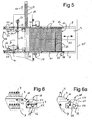
- Figur 5 eine Draufsicht auf die Entladeebene nach Figur 4,
- Figuren 6 und 6a zwei Ausführungen für Teilansichten eines Entladeschlittens mit unterschiedlichen Ausführungen für Visiervorrichtungen,
- Figuren 7 und 8 Schnitte durch eine der Antriebsvorrichtungen für den Entladeschlitten sowie,
- Figuren 9 und 10 Ansichten von Abschnitten der Gelenksysteme.
- Die in den Figuren dargestellte Gefriertrocknungseinrichtung ist mit 1 bezeichnet. Sie umfasst eine nur teilweise dargestellte Kammer 2, in der sich die Stellflächen 3 befinden. Auf einer der Stellflächen sind beispielhaft Behälter 4 dargestellt. Durch seitliche Stege 5 sind die Behälter 4 geführt.
- Mit Hilfe einer im einzelnen nicht näher dargestellten Zylinder-Kolbeneinrichtung sind die Stellflächen 3 in Bezug auf ihre Höhe einstellbar. Diese Höheneinstellung erlaubt es zum einen, die einzelnen Stellflächen 3 auf eine bestimmte Be- bzw. Entladehöhe einzustellen (Beladeöffnung 6). Zum anderen können die Stellflächen 3 mit Hilfe der Zylinder-Kolbeneinrichtung nach der Durchführung der Gefriertrocknung zusammengeschoben werden, um die Behälter 4 zu schließen.
- Frontseitig besitzt die Kammer 2 eine vakuumdicht verschließbare Tür 7, die mit der Beladeöffnung 6 ausgerüstet ist. Diese ist ihrerseits mit der Klappe 8 verschließbar. In Höhe der Beladeöffnung 6 befinden sich vor der Gefriertrocknungseinrichtung 1 Be- und Entladeeinrichtungen, die eine Arbeitsebene 9, ein an die Ebene 9 angrenzendes, der Zu- und Abführung der Behälter 4 dienendes Förderbandsystem 10 sowie Schiebebauteile umfassen. Figur 1 lässt bereits das als Schlitten ausgebildete Bauteil 11 erkennen, dessen Antriebssystem mit 12 bezeichnet ist. Der Schlitten 11 dient - wie weiter unten noch beschrieben - der Entladung der Stellflächen 3. Der Doppelpfeil 13 deutet seine Bewegungsrichtungen an. In seiner zurückgezogenen Stellung - wie dargestellt - stützt er sich auf der Arbeitsebene 9 ab.
- In Figur 1 ist der Isolator 14 angedeutet. Er bildet den Isolatorraum 15, der den der Beladeöffnung 6 vorgelagerten Bereich umgibt. Die Gefriertrocknungskammer 2 bildet eine seitliche Wandung des Isolators 14. Die Beladeöffnung 6 mündet in den Isolatorraum 15. Der Isolatorraum 15 erstreckt sich üblicherweise entlang des Förderbandsystems 10, und zwar auf der Zuführungsseite bis zur Fülleinrichtung für die Behälter und auf der Abführungsseite bis zur Kappen-Verschlussvorrichtung. Die Wandungen des Isolators 14 bestehen zweckmäßig aus durchsichtigem, sterilisierbarem Kunststoff, z.B. Polyethylen.
- Während der Be- und Entladephase muss der Raum zwischen dem Förderband 10 und der jeweiligen Stellfläche 3 durch die Beladeöffnung 6 hindurch überbrückt werden. Dieses geschieht mit Hilfe einer verschiebbaren und ihrem Winkel einstellbaren Platte 17. Das nur schematisch angedeutete Antriebssystem 18 stützt sich unterhalb der Beladeebene ab. Auch die Platte 17 befindet sich - wie dargestellt - in ihrer Ruhestellung unterhalb der Beladeebene. Wie die Stellflächen 3 ist sie mit seitlichen Stegen ausgerüstet, die ein seitliches Herabfallen der Behälter 4 verhindern.
- Anhand der Figuren 2 und 3 sollen weitere Details des Ausführungsbeispieles nach Figur 1 sowie die Beladung einer Stellfläche 3 erläutert werden. Zur Beladung wird nicht der Schlitten 11 eingesetzt; sie erfolgt mit Hilfe eines Schiebers 21.. In den Figuren 2, 3 ist der der Entladung dienende Schlitten 11 aus Gründen der Übersichtlichkeit nicht dargestellt. Schlitten 11 und Schieber 21 sind derart bemessen, das sie einander in ihrer Bewegung nicht behindern.
- Der Schieber 21 ist seitlich mit Zahnstangen 22 ausgerüstet, welche mit Zahnrädern 24 in Eingriff stehen. Die Zahnräder 24 befinden sich unterhalb der Arbeitsebene 9 und greifen durch Öffnungen bis zu den Zahnstangen 22 hindurch. Unterhalb der Arbeitsebene 9 befinden sich ebenfalls der Antrieb 26 sowie die Welle 27 (Figur 3), über die die Zahnräder 24 synchron angetrieben werden. Der Schieber 21 ist als stabiles Gestell mit einer Querstange 28 und der vorderen Frontleiste 29 aufgebaut.
- Dieses Kraftübertragungs-System kann auch ersetzt werden durch in sich gekoppelte Zahnriehmen oder Spindeleinheiten.
Zudem kann die Welle 27 mechanisch und elektrisch (bei elektrischer Ausführung mittels zwei Antrieben) ausgeführt werden. - Zur Beladung einer Stellfläche 3 müssen die vom Förderband 10 angelieferten Behälter 4 zunächst mit Hilfe des Schiebers 21 auf die Stellfläche 3 geschoben werden. Dieses geschieht nach dem Öffnen der Beladeöffnung 6, der Einstellung einer leeren Stellfläche 3 auf ihre Beladehöhe und dem Einfahren der Platte 17 in ihre Betriebsstellung. Danach wird eine nicht dargestellte Sperre geschlossen, die sich auf der in Förderrichtung (Pfeil 31 in Figur 3) abgewandten Seite der Stellfläche 3 befindet. Das Schließen dieser Sperre hat die Wirkung, dass sich die der Stellfläche 3 vorgelagerte Oberfläche des Förderbandes 10 mit Behältern 4 füllt. Ist sie gefüllt, wird das Förderband 10 angehalten. Der Schieber 21 schiebt die Behälter 4 auf die Stellfläche 3. Die Stege 5 sowohl auf der Platte 17 als auch auf der Stellfläche 3 verhindern ein seitliches Herabfallen der Behälter 4.
- In der vorstehend beschriebenen Weise werden alle Stellflächen 3 nacheinander beladen. Ist die Beladung abgeschlossen, erfolgen das Absenken und Zurückziehen der Platte 17, das Verschließen der Beladeöffnung 6 mit Hilfe der Klappe 8 und die Durchführung der Gefriertrocknung des in den Behältern 4 befindlichen Produkts.
- Wie bereits erwähnt, dient der in Figur 1 dargestellte Schlitten 11 der Entladung der Stellfläche 3 nach der Durchführung der Gefriertrocknung und nach dem Verschließen der Behälter 4. Anhand der Figuren 4 und 5 soll der Entladevorgang beschrieben werden.
- In Figur 1 ist der Schlitten 11 in seiner zurückgezogenen Position, in den Figuren 4 und 5 in in die Kammer 2 eingefahrenen Positionen dargestellt. Seine Bewegungsrichtungen kennzeichnet der Doppelpfeil 13. Der Schlitten 11 ist als stabiles Gestell mit Längs- und Querstegen 35, 36 sowie mit Stützen 37 ausgebildet. Frontseitig weist er eine Visiervorrichtung 38 auf (siehe auch Figur 1). Die unteren Enden der Stützen sind mit Rollen 39 - vorzugsweise aus Kunststoff - ausgerüstet, mit denen sich der Schlitten 11 auf seinen Unterlagen (Arbeitsebene 9, Platte 17, Stellflächen 3) abstützt. Die Höhe der Quer- und Längsstege 35, 36 des Schlittens 11 ist so gewählt, dass zum einen der im Bereich der Arbeitsebene 9 befindliche Schieber 21 und zum anderen die Behälter 4 darunter Platz finden. Der Abstand der Stützräder 39 ist so gewählt, dass sich der Schlitten 11 während seiner Bewegung innerhalb der Kammer 2 seitlich auf den Stellflächen 3 abstützt, und zwar außerhalb der Stege 5 befindlichen Rändern 41. Ähnliche Außenränder besitzt auch die Platte 17.
- Der Verschiebung des Schlittens 11 dient das Antriebssystem 12. Es umfasst zwei Gelenksysteme 42, 43, deren freie Enden seitlich am Schlitten 11 - z.B. an den Längsstegen 35 - befestigt sind. Jedem der Gelenksysteme 42, 43 ist ein Antriebsrad 44 bzw. 45 sowie ein darunter befindliches Aufrollsystem 46, 47 zugeordnet. Dieses weiter unten noch im Detail beschriebene Antriebssystem 12 erlaubt die Übertragung von Zug- und Druckkräften auf den Schlitten 11, und zwar über die relativ weite, für den Entladevorgang notwendige Strecke, ohne dass die Gefahr des Entstehens von Abriebpartikeln in die Nähe des Produkts besteht.
- Die Gelenksysteme 42, 43 umfassen starre, gelenkig miteinander verbundene Bauteile bzw. Elemente. Sie bestehen - wie auch der Schlitten 11 - aus VA-Stahl mit gerundeten Oberflächen, um gute Sterilisationsergebnisse zu erzielen.
- Die Figuren 4 und 5 zeigen den Schlitten 11 jeweils in einer Stellung, in der er in die Kammer 2 eingefahren ist. Der der Beladung dienende Schieber 21 befindet sich in seiner zurückgezogenen Stellung (Figur 4). Oberhalb der Arbeitsebene 9 befinden sich seitlich neben den Gelenksystemen 42, 43 erstreckende Stangenabschnitte 48 mit Nuten 49, in denen die Gelenksysteme 42, 43 in ihrer ausgezogenen Stellung oder der Schlitten 11 in seiner zurückgezogenen Stellung geführt sind. Dem Antrieb der Gelenksysteme 42, 43 dienen die Antriebsräder 44, 45. Ihre Drehachsen 40 sind im wesentlichen senkrecht zur Bewegungsrichtung (Doppelpfeil 13) des Schlittens 11 ausgerichtet. Antriebsräder 44, 45 und Aufrollsysteme 46, 47 liegen in einer Ebene. Der Erzeugung der synchronen Drehbewegung der Antriebsräder 44, 45 dienen aus Getrieben 50 und Wellenabschnitten 51 bestehende Antriebsmittel, die mit dem Antriebsmotor 52 gekoppelt sind (Fig. 5). Die Erzeugung der synchronen Drehbewegung kann auch mittels elektrischer Verbindung (mittels zwei Antrieben) erzeugt werden.
- Sowohl die beschriebenen Antriebsmittel als auch die jeweiligen Antriebsräder 44, 45 mit ihren Aufrollsystemen 46, 47 befinden sich in Teilräumen des Isolators 14. Entsprechende Wandungsabschnitte sind mit 53 bezeichnet.
- Die Entladung der Kammer 2 erfolgt nach der Durchführung der Gefriertrocknung, der Belüftung der Kammer 2, dem Öffnen der Beladeöffnung 6 und dem Einfahren der Platte 17 in seine Betriebsstellung. Jede der Stellflächen 3 wird nacheinander in die Be- bzw. Entladehöhe gefahren und folgendermaßen entladen: Der Schlitten 11 wird in die Kammer 2 eingefahren, und zwar so weit, bis sich seine Visiervorrichtung 38 (siehe auch Figuren 6 und 6a) - von der Beladeöffnung 6 her gesehen - hinter dem Behälterpaket befindet. Bestandteil der Visiervorrichtung 38 ist ein Visier 54, das sich während des Einfahrens des Schlittens 11 in die Kammer 2 in seiner angehobenen Stellung befindet und die Behälter 4 nicht berührt. Durch den Kontakt der Visiervorrichtung 38 mit der Kammerrückwand 55 wird das Absenken des Visiers 54 ausgelöst. Danach erfolgt das Zurückziehen des Schlittens 11, entweder abschnittsweise um etwa die Breite des Förderbandes 10 oder so langsam, dass die Behälter 4 bei laufendem Förderband 10 störungsfrei abgefördert werden können. Während seiner Bewegung ist der Schlitten ständig seitlich geführt, und zwar auf den Stellflächen 3 und der Platte 17 durch die jeweiligen seitlichen Stege, auf der Arbeitsebene 9 durch die Stangenabschnitte 48.
- In den Figuren 6 und 6a sind die Visiervorrichtungen 38 jeweils vergrößert dargestellt. Bestandteil der Visiervorrichtung 38 sind seitliche Trägerscheiben 56, in denen das Visier 54 drehbar gelagert ist. Das Visier 54 ist sowohl in seiner angehobenen (gestrichelt) als auch in seiner abgesenkten Stellung dargestellt. Die Betätigung des Visiers 54 ist derart ausgebildet, dass es nicht erforderlich ist, Kabelverbindungen über die Behälter 4 zu schleppen. Figur 6 zeigt eine mechanische Lösung. Eine in Richtung des Doppelpfeiles 13 verschiebbare Zahnstange 57, z.B. Rundzahnstange, steht mit einem Zahnrad 58 in Eingriff. Während des Einfahrens des Schlittens 11 in die Kammer 2, d.h. bei angehobenem Visier 54 (gestrichelt), ragt die Zahnstange 57 aus der Frontseite der Trägerscheibe 56 hervor. Durch ihren Kontakt mit der Kammerrückwand 55 wird die Zahnstange relativ zur Trägerscheibe 57 zurückbewegt und bewirkt über das Zahnrad 58 das Absenken des Visiers 54. Danach erfolgt der Beginn der Rückwärtsbewegung des Schlittens 11 - veranlasst beispielsweise durch einen Stellungsgeber des Antriebssystems 12 - und der bereits beschriebene Entladevorgang.
- Anhand der Figur 6a soll eine elektrische Lösung für die Betätigung des Visiers 54 beschrieben werden, die dennoch den Vorteil hat, dass auf Kabelschlepps verzichtet werden kann. Die Trägerscheibe 56 trägt einen Stellmotor 59, der mit dem Visier 54 gekoppelt ist. Seine Betätigung erfolgt beispielsweise mit Hilfe des bereits erwähnten Gebers am Antriebssystem 12. Der Übertragung von Signal- und Betätigungsströmen dienen die Gelenksysteme 42, 43, je nach Ausführung zumindest eines dieser Systeme, sowie die Längsstege 35 des Schlittens 11. Voraussetzungen für die Lösung sind, dass die Gelenksysteme - unabhängig von ihrer sonstigen Gestaltung - sowie die Längsstege 35 des Schlittens 11 elektrisch leitend sind und bezüglich anderer Bauteile, mit denen sie Kontakt haben, elektrische Isolationen vorhanden sind. Um den Kontakt zwischen einem Gelenksystem 42, 43 und einer Stromquelle oder einer Steuereinrichtung herzustellen, ist im Bereich der Arbeitsebene 9 z.B. ein - nicht dargestellter - Kontakt vorgesehen.
- Die Figuren 7 und 8 zeigen Einzelheiten eines Antriebsrades 45 für die Gliederkette 43 und seines zugehörigen Aufrollsystems 47. Bei der Figur 8 handelt es sich um einen Querschnitt entsprechend der Linie VIII-VIII in Figur 7. Figur 8 zeigt weiterhin Teile der Antriebsmittel 50, 51. Antriebsrad 45 und Aufrollsystem 47 befinden sich in einem entlang der Linien 61 teilbaren Gehäuse 62, so dass sie jeweils in einer separaten Kassette 63, 64 untergebracht sind. Das Gehäuse 62 umfasst eine Grundscheibe 66, auf der zwei weitere Scheiben 67 und 68 lösbar (Schraubverbindungen 69) befestigt sind. Die einander zugewandten Seiten der Scheiben 67,68 sind mit Ausnehmungen versehen, die im Bereich der Kassette 63 einen das Antriebsrad 45 aufnehmenden Hohlraum 71 und im Bereich der Kassette einen spiralförmigen Hohlraum 72 zur Aufnahme der Gliederkette 43 bilden. Als Werkstoff für das Gehäuse 62 wird zweckmäßig ein sterilisierbarer Kunststoff verwendet.
- Die Gelenksysteme 43, 44 bestehen - wie in den Figuren 9, 10 zum Gelenksystem 43 dargestellt - aus gelenkig miteinander verbundenen Stangenabschnitten 76, deren eines Ende 75 U-förmig und deren anderes Ende einen Abschnitt 77 mit ebenen Seitenflächen aufweist. Gemeinsam mit einem beide Endstücke 75, 77 durchsetzenden Stift 78 bilden sie die jeweiligen Gelenke. Die Stifte 78 ragen seitlich aus den Gelenksystemen 43, 44 hervor. Sie bilden Stümpfe 79, die zur Führung der Gelenksysteme 43, 44 verwendet werden.
- Um Zug- und Druckkräfte auf das Gelenksystem 43 ausüben zu können, weist das Antriebsrad 45 periphere Ausnehmungen 81 im Abstand der Stümpfe 79 auf. Die von unten aus der Öffnung 82 in der Kassette 64 aus- bzw. eintretende Kette 43 greift über einen Teilumfang des Antriebsrades 45 mit ihren Stümpfen 79 in die Ausnehmungen 81 ein, so dass eine kraftschlüssige Verbindung vorhanden ist. Die Ein-, Austrittsöffnung für die Kette 43 aus der Kassette 63 ist mit 82 bezeichnet (Figur 7).
- Im Bereich der Kassette 64 ist der spiralförmige Hohlraum 72 mit seitlichen Nuten 84, 85 ausgerüstet. In diese Nuten greifen die Stümpfe 79 der Kette 43 ein, so dass die Kette 43 platzsparend in der Kassette 64 untergebracht werden kann.
- Im Bereich des inneren Endes des spiralförmigen Hohlraumes 72 befindet sich eine Öffnung 86. An diese Öffnung ist eine Einrichtung angeschlossen, die den Isolatorraum 15 mit sterilen Gasen, z.B. sterile Luft, versorgt. Dadurch, dass zumindest ein Teil dieser Gase durch die Öffnung 86 eintritt, können auch die Hohlräume 72 und 71 in den Kassetten 64, 63 insbesondere während des Betriebs steril gehalten werden. Außerhalb der Betriebszeiten wird der Innenraum des Isolators 14 dekontaminiert. Während dieser Prozesse werden Sterilisationsgase, z.B. Wasserstoffperoxid, eingelassen. Dieses geschieht ebenfalls durch die Öffnungen 86, so dass die Hohlräume 71 und 72 einbezogen sind
Claims (24)
- Einrichtung (1) mit mindestens einer Stellfläche (3) für Behälter (4) sowie mit einer der Beladung und/oder Entladung dienenden Vorrichtung, die ein auf die Stellfläche (3) aufschiebbares und wieder zurückziehbares Bauteil (11) sowie einen Antrieb (12) dafür aufweist, dadurch gekennzeichnet, dass Bestandteile des Antriebs (12) mindestens ein Antriebsrad (44, 45), ein Gelenksystem (42, 43) und ein Aufrollsystem (46, 47) für das Gelenksystem (42, 43) sind, dass das Antriebsrad (44, 45) um eine sich etwa senkrecht zur Bewegungsrichtung des Bauteils (11) erstreckende Achse (40) drehbar ist und dass das Aufrollsystem (46,47) in der Ebene des Antriebsrades (44, 45) angeordnet ist.
- Einrichtung nach Anspruch 1, dadurch gekennzeichnet, dass sich auf der Be-/Entladeseite der Stellfläche (3) eine Arbeitsebene (9) und ein Förderbandsystem (10) befinden.
- Einrichtung nach Anspruch 2, dadurch gekennzeichnet, dass das zwischen der Arbeitsebene (9) und der Stellfläche (3) befindliche Förderbandsystem (10) an die Arbeitsebene (9) angrenzt und dass eine verstellbare Platte (17) vorgesehen ist, die in ihrer Betriebsstellung den Raum zwischen dem Förderbandsystem (10) und der Stellfläche (3) überbrückt.
- Einrichtung nach Anspruch 3, dadurch gekennzeichnet, dass die Stellfläche (3) und die Platte (17) mit seitlichen Stegen zur Führung der Behälter (4) ausgerüstet sind und dass sich außerhalb der Stege Randbereiche befinden, auf denen sich das verschiebbare Bauteil (11) abstützt.
- Einrichtung nach einem der vorhergehenden Ansprüche, dadurch gekennzeichnet, dass das Bauteil (11) ein aus Längs- und Querstegen (35, 36) bestehender Schlitten ist, der sich über Stützen (3.7) und Rollen (39) auf seiner Unterlage abstützt.
- Einrichtung nach Anspruch 5, dadurch gekennzeichnet, dass jeder der Längsstege (35) des Schlittens (11) mit einem der beiden Gelenksysteme (42, 43) in Verbindung steht.
- Einrichtung nach Anspruch 5 oder 6, dadurch gekennzeichnet, dass die Frontseite des Schlittens (11) mit einer Visiervorrichtung (38) ausgerüstet ist, die ein in zwei Positionen einstellbares Visier (54) trägt.
- Einrichtung nach Anspruch 7, dadurch gekennzeichnet, dass das Visier (54) mechanisch betätigbar ist.
- Einrichtung nach Anspruch 8, dadurch gekennzeichnet, dass die Visiervorrichtung (38) mit einer längsgerichteten Zahnstange (57) ausgerüstet ist, die mit einem mit dem Visier (54) verbundenen Zahnrad (58) in Eingriff steht.
- Einrichtung nach Anspruch 9, dadurch gekennzeichnet, dass die Visiervorrichtung elektrisch betätigbar ist.
- Einrichtung nach Anspruch 10, dadurch gekennzeichnet, dass die Visiervorrichtung mit einem Stellmotor (59) zur Einstellung des Visiers (54) in eine seiner beiden Positionen ausgerüstet ist und dass mindestens eines der beiden Gelenksysteme (42, 43) als Leiter für die Übertragung von Signal- und/oder Betätigungsströmen verwendet wird.
- Einrichtung nach einem der vorhergehenden Ansprüche, dadurch gekennzeichnet, dass Bestandteile des Gelenksystems (42, 43) starre, gelenkig miteinander verbundene Bauteile (76), vorzugsweise aus VA-Stahl mit gerundeten Oberflächen, sind.
- Einrichtung nach Anspruch 12, dadurch gekennzeichnet, dass Bestandteil der Gelenke Stahlstifte (78) sind, die in Form seitlicher Stümpfe (79) aus den Gelenken hervorragen.
- Einrichtung nach Anspruch 13, dadurch gekennzeichnet, dass das Antriebsrad (44, 45) mit peripheren Ausnehmungen (81) im Abstand der Stümpfe (79) ausgerüstet ist.
- Einrichtung nach Anspruch 13 oder 14, dadurch gekennzeichnet, dass Bestandteil des Aufrollsytems (46, 47) ein spiralförmiger Hohlraum (72) mit seitlichen Nuten (84, 85) ist, in denen die Stümpfe (79) des -Gelenksystems (42, 43) geführt sind.
- Einrichtung nach einem der vorhergehenden Ansprüche, dadurch gekennzeichnet, dass für das Antriebsrad (44, 45) und für das Aufrollsystem (46, 47) ein Gehäuse (62) vorgesehen ist und dass sich im Gehäuse Hohlräume (71, 72) befinden, die der Aufnahme des Antriebsrades (44, 45) bzw. des Gelenksystems (42, 43) dienen.
- Einrichtung nach Anspruch 16, dadurch gekennzeichnet, dass das Gehäuse (62) aus zwei lösbar miteinander verbundenen Teilgehäusen (63, 64) besteht, von denen eines den Hohlraum (71) und das andere den spiralförmigen Hohlraum (72) aufweist, und dass beide Gehäuseteile (63, 64) lösbar an der Einrichtung (1) befestigt sind.
- Einrichtung nach einem der vorhergehenden Ansprüche, dadurch gekennzeichnet, dass sie mit einem Isolator (14) ausgerüstet ist.
- Einrichtung nach Anspruch 18 und einem der Ansprüche 16 oder 17, dadurch gekennzeichnet, dass die Hohlräume (71, 72) im Gehäuse (62) Bestandteile des Isolatorraums (15) sind.
- Einrichtung nach Anspruch 19, dadurch gekennzeichnet, dass sich im Bereich des inneren Endes des spiralförmigen Hohlraums (72) eine Öffnung (86) befindet, die mit einer Quelle für sterile Gase verbindbar ist.
- Einrichtung nach einem der vorhergehenden Ansprüche, dadurch gekennzeichnet, dass sie zusätzlich mit einem der Beladung der Stellfläche (3) dienenden Schieber (21) ausgerüstet ist.
- Einrichtung nach Anspruch 21, dadurch gekennzeichnet, dass das Bauteil (11) und der Beladeschieber (21) sich auf der Beladeseite befinden und derart ausgebildet sind, dass sie einander bei ihrer Bewegung nicht behindern.
- Einrichtung nach einem der vorhergehenden Ansprüche, dadurch gekennzeichnet, dass sie als Gefriertrocknungseinrichtung (1) mit einer Kammer (2) ausgebildet ist, in der sich eine Mehrzahl übereinander angeordneter Stellflächen (3) befinden.
- Einrichtung nach Anspruch 23, dadurch gekennzeichnet, dass die Kammer (2) mit einer Be-/Entladeöffnung (6) ausgerüstet ist, der die Vorrichtungen zur Be- und/oder Entladung vorgelagert sind.
Priority Applications (1)
| Application Number | Priority Date | Filing Date | Title |
|---|---|---|---|
| SI200430249T SI1594780T1 (sl) | 2003-02-22 | 2004-02-05 | Naprava z odlagalno ploskvijo |
Applications Claiming Priority (3)
| Application Number | Priority Date | Filing Date | Title |
|---|---|---|---|
| DE10307571A DE10307571A1 (de) | 2003-02-22 | 2003-02-22 | Einrichtung mit einer Stellfläche |
| DE10307571 | 2003-02-22 | ||
| PCT/EP2004/001058 WO2004074143A1 (de) | 2003-02-22 | 2004-02-05 | Einrichtung mit einer stellfläche |
Publications (2)
| Publication Number | Publication Date |
|---|---|
| EP1594780A1 EP1594780A1 (de) | 2005-11-16 |
| EP1594780B1 true EP1594780B1 (de) | 2007-01-03 |
Family
ID=32797645
Family Applications (1)
| Application Number | Title | Priority Date | Filing Date |
|---|---|---|---|
| EP04708348A Expired - Lifetime EP1594780B1 (de) | 2003-02-22 | 2004-02-05 | Einrichtung mit einer stellfläche |
Country Status (11)
| Country | Link |
|---|---|
| US (1) | US7695230B2 (de) |
| EP (1) | EP1594780B1 (de) |
| JP (1) | JP2006518319A (de) |
| AT (1) | ATE350314T1 (de) |
| AU (1) | AU2004213113A1 (de) |
| DE (2) | DE10307571A1 (de) |
| DK (1) | DK1594780T3 (de) |
| ES (1) | ES2280942T3 (de) |
| PT (1) | PT1594780E (de) |
| SI (1) | SI1594780T1 (de) |
| WO (1) | WO2004074143A1 (de) |
Families Citing this family (40)
| Publication number | Priority date | Publication date | Assignee | Title |
|---|---|---|---|---|
| GB0413115D0 (en) * | 2004-06-11 | 2004-07-14 | Boc Group Plc | Freeze dryer |
| GB0413117D0 (en) * | 2004-06-11 | 2004-07-14 | Boc Group Plc | Freeze dryer |
| ES2279326T5 (es) * | 2004-07-22 | 2013-04-08 | Telstar Technologies, S.L. | Dispositivo para la carga y descarga de recipiente |
| EP1867381A4 (de) | 2005-03-29 | 2010-05-26 | Yanmar Co Ltd | Abgasreiniger |
| DE102005017140A1 (de) | 2005-04-13 | 2006-10-19 | Steris Gmbh | Verfahren zum Betrieb von Gefriertrocknungsanlagen mit einer Kammer und mit Be- und Entladeeinrichtungen sowie dafür geeignet ausgebildete Anlagen dieser Art |
| DE102005019985B4 (de) * | 2005-04-27 | 2010-12-30 | Accurro Gmbh | Verfahren zum kontrollierten Herausführen einer Anzahl von Vials aus einer Gefriertrocknungsanlage und Vorrichtung hierfür |
| WO2007131760A1 (en) * | 2006-05-12 | 2007-11-22 | Ima Life S.R.L. | Loading system for a freeze dryer |
| ES2422210T3 (es) * | 2006-07-18 | 2013-09-09 | Telstar Technologies S L U | Aparato para mover recipientes |
| FR2918653A1 (fr) * | 2007-07-13 | 2009-01-16 | Usifroid Sa Sa | Dispositif de dechargement d'une armoire de traitement de produits |
| DE102007034084B3 (de) * | 2007-07-21 | 2008-09-04 | Motus Engineering Gmbh & Co. Kg | Vorrichtung zum Be- und Entladen einer Stellplatte einer Gefriertrocknungsanlage und ein Verfahren hierfür |
| DE102007034197B4 (de) * | 2007-07-23 | 2013-06-06 | Accurro Gmbh | Vorrichtung zum Be- und Entladen einer Stellplatte einer Gefriertrocknungsanlage und ein Verfahren hierfür |
| DE102008020705A1 (de) | 2008-04-24 | 2009-10-29 | Gea Lyophil Gmbh | Be- und Entladevorrichtung für eine Produktbehandlungseinrichtung |
| DE202008012379U1 (de) * | 2008-09-18 | 2008-12-24 | Gea Lyophil Gmbh | Transfervorrichtung für eine Gefriertrocknungsanlage |
| US8683712B2 (en) * | 2008-10-23 | 2014-04-01 | Samsung Electronics Co., Ltd. | Lyophilizing tray employing reagent cartridge, lyophilizing system employing the same, and method of preparing lyophilized reagent |
| DE102008064094A1 (de) * | 2008-12-19 | 2010-07-01 | Accurro Gmbh | Gefriertrocknungsanlage und Vorrichtung zum Be- und Entladen einer Stellplatte einer Gefriertrocknungsanlage |
| NL2003338C2 (en) * | 2009-08-07 | 2011-02-08 | Ima Life Srl | Method and assembly for handling containers in a freeze dryer. |
| DE102009049142B4 (de) | 2009-10-12 | 2013-06-27 | Martin Christ Gefriertrocknungsanlagen Gmbh | Be- und Entladevorrichtung für eine Gefriertrocknungsanlage |
| DE102010047744A1 (de) | 2010-10-11 | 2012-04-12 | Martin Christ Gefriertrocknungsanlagen Gmbh | Be- und Entladevorrichtung für eine Gefriertrocknungsanlage |
| CN102305517A (zh) * | 2011-06-19 | 2012-01-04 | 上海东富龙科技股份有限公司 | 一种原料药冻干托盘自动转运至冻干机板层的方法 |
| DE102011117628B4 (de) | 2011-11-04 | 2015-10-22 | Martin Christ Gefriertrocknungsanlagen Gmbh | Gefriertrockungsanlage mit einer Be- und Entladevorrichtung |
| ES2626445T3 (es) * | 2012-03-14 | 2017-07-25 | I.M.A. Industria Macchine Automatiche S.P.A. | Aparato para mover recipientes |
| CN105501503B (zh) * | 2012-05-03 | 2018-01-12 | 肖特公开股份有限公司 | 用于处理或加工容器的方法和设备 |
| ITMI20121275A1 (it) * | 2012-07-23 | 2014-01-24 | I M A Ind Macchine Automatic He S P A | Apparato di movimentazione di piani di carico per macchine liofilizzatrici |
| CN103896058B (zh) * | 2012-12-26 | 2016-12-28 | 楚天科技股份有限公司 | 用于冻干箱的进出瓶组件及进出瓶方法 |
| CN103033032B (zh) * | 2013-01-15 | 2015-02-18 | 上海东富龙科技股份有限公司 | 一种冻干机的自动进出料装置 |
| CN103673568B (zh) * | 2013-01-31 | 2016-08-03 | 楚天科技股份有限公司 | 一种冻干机 |
| WO2014117690A2 (zh) * | 2013-01-31 | 2014-08-07 | 楚天科技股份有限公司 | 一种冻干机 |
| ITMI20130465A1 (it) * | 2013-03-27 | 2014-09-28 | I M A Ind Macchine Automatic He S P A | Apparato di trasferimento e relativo metodo di trasferimento |
| ITMI20130841A1 (it) * | 2013-05-23 | 2014-11-24 | I M A Ind Macchine Automatic He S P A | Dispositivo introduttore di flaconi |
| ITUA20161823A1 (it) * | 2016-03-18 | 2017-09-18 | I M A Industria Macch Automatiche S P A In Sigla Ima S P A | Apparato per caricare e scaricare un liofilizzatore. |
| US10788264B2 (en) * | 2016-04-12 | 2020-09-29 | Vanrx Pharmasystems, Inc. | Method and apparatus for loading a lyophilization system |
| US10703575B2 (en) * | 2016-09-26 | 2020-07-07 | Azbil Corporation | Conveyance device |
| EP3517462B1 (de) * | 2016-09-26 | 2023-08-09 | Azbil Corporation | Fördervorrichtung |
| WO2018055758A1 (ja) * | 2016-09-26 | 2018-03-29 | アズビル株式会社 | 搬送システム |
| JP2018095389A (ja) | 2016-12-12 | 2018-06-21 | アズビル株式会社 | 搬送装置 |
| US11268759B2 (en) | 2017-03-24 | 2022-03-08 | Azbil Corporation | Housing device |
| ES2774058T3 (es) * | 2017-04-21 | 2020-07-16 | Gea Lyophil Gmbh | Un liofilizador y un método para inducir la nucleación en los productos |
| EP3499160B1 (de) | 2017-12-15 | 2020-02-26 | Martin Christ Gefriertrocknungsanlagen GmbH | Gefriertrockner, gefriertrocknungsanlage, verfahren zum betrieb eines gefriertrockners und neue verwendung eines schlittens |
| AT524336B1 (de) * | 2020-10-23 | 2022-10-15 | Tgw Logistics Group Gmbh | Verfahren und Vorrichtungen zum Handhaben und Überprüfen von Transportgestellen für eine Auslieferung von Waren |
| US20240210111A1 (en) * | 2021-04-19 | 2024-06-27 | Sbm Schoeller Bleckmann Medizintechnik Gmbh | Freeze drying installation |
Family Cites Families (16)
| Publication number | Priority date | Publication date | Assignee | Title |
|---|---|---|---|---|
| US2457240A (en) * | 1946-09-23 | 1948-12-28 | United Shoe Machinery Corp | Shield for gun mounts |
| US2793736A (en) * | 1953-12-01 | 1957-05-28 | Ely K Thomson | Conveyor system |
| US3516469A (en) * | 1969-01-02 | 1970-06-23 | Bruce D Mcdonald | Power operated flexible wall section |
| US3944037A (en) * | 1973-07-23 | 1976-03-16 | Stease Ralph E | Rail structure for a conveyor |
| DE3408080A1 (de) * | 1984-03-05 | 1985-09-05 | Rhein-Bayern-Fahrzeugbau GmbH & Co KG, 8950 Kaufbeuren | Abdeckung fuer montagegruben |
| JPS62180802A (ja) * | 1986-02-04 | 1987-08-08 | Tanabe Seiyaku Co Ltd | 物品収容装置 |
| DE3702965A1 (de) * | 1987-02-02 | 1988-08-11 | Adolf Stambera | Einrichtung zum einlegen von zwischenlagen bei palettiermaschinen |
| DE9001612U1 (de) * | 1989-04-07 | 1990-04-19 | Finn-Aqua Santasalo-Sohlberg GmbH, 50354 Hürth | Vorrichtung zum Beschicken und Entladen einer Gefriertrocknungseinrichtung |
| US5106259A (en) * | 1991-01-22 | 1992-04-21 | Robotic Originals, Inc. | Method for loading transport racks |
| DE4215781A1 (de) * | 1992-05-13 | 1993-11-18 | Santasalo Sohlberg Finn Aqua | Transfertisch |
| JP2588973Y2 (ja) * | 1993-08-06 | 1999-01-20 | 石川島運搬機械株式会社 | 機械式駐車装置 |
| DE4424287C2 (de) * | 1994-07-09 | 2001-05-31 | Koenig & Bauer Ag | Hilfsstapeleinrichtung |
| DE29507589U1 (de) * | 1995-05-06 | 1995-07-13 | Kelly, Douglas, Dipl.-Ing., 69120 Heidelberg | Beschickungsanlage für pharmazeutische Anlagen für in Gefäße oder Behältnissen befindlichen pharmazeutischen Produkten |
| JPH11141639A (ja) * | 1997-10-31 | 1999-05-25 | Pentel Kk | 直動繰り出し装置 |
| DE10060697B4 (de) * | 2000-12-07 | 2005-10-06 | Siltronic Ag | Doppelseiten-Polierverfahren mit reduzierter Kratzerrate und Vorrichtung zur Durchführung des Verfahrens |
| DE102005017140A1 (de) * | 2005-04-13 | 2006-10-19 | Steris Gmbh | Verfahren zum Betrieb von Gefriertrocknungsanlagen mit einer Kammer und mit Be- und Entladeeinrichtungen sowie dafür geeignet ausgebildete Anlagen dieser Art |
-
2003
- 2003-02-22 DE DE10307571A patent/DE10307571A1/de not_active Withdrawn
-
2004
- 2004-02-05 EP EP04708348A patent/EP1594780B1/de not_active Expired - Lifetime
- 2004-02-05 DE DE502004002543T patent/DE502004002543D1/de not_active Expired - Lifetime
- 2004-02-05 SI SI200430249T patent/SI1594780T1/sl unknown
- 2004-02-05 PT PT04708348T patent/PT1594780E/pt unknown
- 2004-02-05 ES ES04708348T patent/ES2280942T3/es not_active Expired - Lifetime
- 2004-02-05 DK DK04708348T patent/DK1594780T3/da active
- 2004-02-05 WO PCT/EP2004/001058 patent/WO2004074143A1/de not_active Ceased
- 2004-02-05 US US10/546,461 patent/US7695230B2/en active Active
- 2004-02-05 AT AT04708348T patent/ATE350314T1/de not_active IP Right Cessation
- 2004-02-05 JP JP2006501743A patent/JP2006518319A/ja active Pending
- 2004-02-05 AU AU2004213113A patent/AU2004213113A1/en not_active Abandoned
Also Published As
| Publication number | Publication date |
|---|---|
| ATE350314T1 (de) | 2007-01-15 |
| WO2004074143A1 (de) | 2004-09-02 |
| AU2004213113A1 (en) | 2004-09-02 |
| DE502004002543D1 (de) | 2007-02-15 |
| SI1594780T1 (sl) | 2007-08-31 |
| DK1594780T3 (da) | 2007-05-14 |
| PT1594780E (pt) | 2007-04-30 |
| US20060263179A1 (en) | 2006-11-23 |
| US7695230B2 (en) | 2010-04-13 |
| JP2006518319A (ja) | 2006-08-10 |
| EP1594780A1 (de) | 2005-11-16 |
| ES2280942T3 (es) | 2007-09-16 |
| DE10307571A1 (de) | 2004-09-02 |
Similar Documents
| Publication | Publication Date | Title |
|---|---|---|
| EP1594780A1 (de) | Einrichtung mit einer stellfläche | |
| EP3144618B1 (de) | Gefriertrockungsanlagen-schlitten und gefriertrocknungsanlage | |
| EP2085490B1 (de) | Vorrichtung zum Tempern von Gegenständen | |
| EP0028347B1 (de) | Transportierbare Vorrichtung für die Aufnahme von gegenüber der Umwelt abzuschirmenden Substanzen | |
| EP2488808B1 (de) | Be- und entladevorrichtung für eine gefriertrocknungsanlage | |
| DE202008018226U1 (de) | Vorrichtung zum Übertragen von Produkten in einer Verkaufsmaschine | |
| DE102005046838A1 (de) | Vorrichtung zum Heben und Drehen von Behältern in einer Reinraumumgebung | |
| EP0782686B1 (de) | Beschickungsanlagen für behandlungsanlagen von in gefässen oder behältnissen befindlichen stoffen | |
| DE10304012B4 (de) | Klimaschrank | |
| EP2627959A1 (de) | Be- und entladevorrichtung für eine gefriertrocknungsanlage | |
| DE69119157T2 (de) | Schneckenanordnung zum Austrag des in einem Silo zurückgebliebenen Produktes | |
| DE3852228T2 (de) | Vorrichtung und Verfahren für die Zellkultur. | |
| EP3499160B1 (de) | Gefriertrockner, gefriertrocknungsanlage, verfahren zum betrieb eines gefriertrockners und neue verwendung eines schlittens | |
| EP0383257B1 (de) | Lagereinrichtung | |
| DE2924050C2 (de) | Verfahren und Einrichtung zur Reinigung und Desinfektion von Transportbehältern | |
| DE3028744C2 (de) | ||
| DE102022103429B3 (de) | Be- und Entladeeinrichtung für einen Gefriertrockner, Verfahren und Gefriertrocknungsanlage | |
| WO1994021577A1 (de) | Kompostiereinrichtung | |
| DE102018220955A1 (de) | Lageranordnung mit nebeneinander angeordneten Lagersystemen und einem Kommissioniersystem mit hin und her beweglichen Kommissionierwagen | |
| DE2925394A1 (de) | Industrieofen | |
| DE2626921C2 (de) | Anordnung zum Beschicken eines horizontalen Behälters zur chargenweisen Behandlung von Gegenständen | |
| DE2725102C3 (de) | Vorrichtung zum Bestrahlen von Stuckgut | |
| DE1805351C3 (de) | Elektrisch beheizter Vakuumofen | |
| DE594611C (de) | ||
| DE2021723C (de) | Vorrichtung zum Stapeln von Kartons od dgl in vorbestimmbaren Lademustern |
Legal Events
| Date | Code | Title | Description |
|---|---|---|---|
| PUAI | Public reference made under article 153(3) epc to a published international application that has entered the european phase |
Free format text: ORIGINAL CODE: 0009012 |
|
| 17P | Request for examination filed |
Effective date: 20050903 |
|
| AK | Designated contracting states |
Kind code of ref document: A1 Designated state(s): AT BE BG CH CY CZ DE DK EE ES FI FR GB GR HU IE IT LI LU MC NL PT RO SE SI SK TR |
|
| AX | Request for extension of the european patent |
Extension state: AL LT LV MK |
|
| DAX | Request for extension of the european patent (deleted) | ||
| GRAP | Despatch of communication of intention to grant a patent |
Free format text: ORIGINAL CODE: EPIDOSNIGR1 |
|
| GRAS | Grant fee paid |
Free format text: ORIGINAL CODE: EPIDOSNIGR3 |
|
| GRAA | (expected) grant |
Free format text: ORIGINAL CODE: 0009210 |
|
| AK | Designated contracting states |
Kind code of ref document: B1 Designated state(s): AT BE BG CH CY CZ DE DK EE ES FI FR GB GR HU IE IT LI LU MC NL PT RO SE SI SK TR |
|
| PG25 | Lapsed in a contracting state [announced via postgrant information from national office to epo] |
Ref country code: FI Free format text: LAPSE BECAUSE OF FAILURE TO SUBMIT A TRANSLATION OF THE DESCRIPTION OR TO PAY THE FEE WITHIN THE PRESCRIBED TIME-LIMIT Effective date: 20070103 |
|
| REG | Reference to a national code |
Ref country code: GB Ref legal event code: FG4D Free format text: NOT ENGLISH |
|
| REF | Corresponds to: |
Ref document number: 502004002543 Country of ref document: DE Date of ref document: 20070215 Kind code of ref document: P |
|
| REG | Reference to a national code |
Ref country code: IE Ref legal event code: FG4D Free format text: LANGUAGE OF EP DOCUMENT: GERMAN |
|
| PG25 | Lapsed in a contracting state [announced via postgrant information from national office to epo] |
Ref country code: MC Free format text: LAPSE BECAUSE OF NON-PAYMENT OF DUE FEES Effective date: 20070228 |
|
| PG25 | Lapsed in a contracting state [announced via postgrant information from national office to epo] |
Ref country code: BG Free format text: LAPSE BECAUSE OF FAILURE TO SUBMIT A TRANSLATION OF THE DESCRIPTION OR TO PAY THE FEE WITHIN THE PRESCRIBED TIME-LIMIT Effective date: 20070403 |
|
| REG | Reference to a national code |
Ref country code: SE Ref legal event code: TRGR |
|
| REG | Reference to a national code |
Ref country code: PT Ref legal event code: SC4A Free format text: AVAILABILITY OF NATIONAL TRANSLATION Effective date: 20070328 |
|
| RAP2 | Party data changed (patent owner data changed or rights of a patent transferred) |
Owner name: GEA LYOPHIL GMBH |
|
| REG | Reference to a national code |
Ref country code: DK Ref legal event code: T3 |
|
| GBT | Gb: translation of ep patent filed (gb section 77(6)(a)/1977) |
Effective date: 20070419 |
|
| REG | Reference to a national code |
Ref country code: PT Ref legal event code: PD4A Owner name: GEA LYOPHIL GMBH, DE Effective date: 20070608 |
|
| REG | Reference to a national code |
Ref country code: CH Ref legal event code: NV Representative=s name: R. A. EGLI & CO. PATENTANWAELTE Ref country code: CH Ref legal event code: PFA Owner name: GEA LYOPHIL GMBH Free format text: STERIS GMBH#KALSCHEURENER STRASSE 92#50354 HUERTH (DE) -TRANSFER TO- GEA LYOPHIL GMBH#KALSCHEURENER STRASSE 96#50354 HUERTH (DE) |
|
| NLT2 | Nl: modifications (of names), taken from the european patent patent bulletin |
Owner name: GEA LYOPHIL GMBH Effective date: 20070502 |
|
| ET | Fr: translation filed | ||
| REG | Reference to a national code |
Ref country code: ES Ref legal event code: FG2A Ref document number: 2280942 Country of ref document: ES Kind code of ref document: T3 |
|
| PLBE | No opposition filed within time limit |
Free format text: ORIGINAL CODE: 0009261 |
|
| STAA | Information on the status of an ep patent application or granted ep patent |
Free format text: STATUS: NO OPPOSITION FILED WITHIN TIME LIMIT |
|
| 26N | No opposition filed |
Effective date: 20071005 |
|
| PG25 | Lapsed in a contracting state [announced via postgrant information from national office to epo] |
Ref country code: RO Free format text: LAPSE BECAUSE OF FAILURE TO SUBMIT A TRANSLATION OF THE DESCRIPTION OR TO PAY THE FEE WITHIN THE PRESCRIBED TIME-LIMIT Effective date: 20070103 |
|
| PG25 | Lapsed in a contracting state [announced via postgrant information from national office to epo] |
Ref country code: GR Free format text: LAPSE BECAUSE OF FAILURE TO SUBMIT A TRANSLATION OF THE DESCRIPTION OR TO PAY THE FEE WITHIN THE PRESCRIBED TIME-LIMIT Effective date: 20070404 |
|
| PGFP | Annual fee paid to national office [announced via postgrant information from national office to epo] |
Ref country code: DK Payment date: 20080228 Year of fee payment: 5 |
|
| PGFP | Annual fee paid to national office [announced via postgrant information from national office to epo] |
Ref country code: GB Payment date: 20080227 Year of fee payment: 5 Ref country code: IE Payment date: 20080227 Year of fee payment: 5 Ref country code: SE Payment date: 20080227 Year of fee payment: 5 |
|
| PGFP | Annual fee paid to national office [announced via postgrant information from national office to epo] |
Ref country code: BE Payment date: 20080306 Year of fee payment: 5 |
|
| PG25 | Lapsed in a contracting state [announced via postgrant information from national office to epo] |
Ref country code: EE Free format text: LAPSE BECAUSE OF FAILURE TO SUBMIT A TRANSLATION OF THE DESCRIPTION OR TO PAY THE FEE WITHIN THE PRESCRIBED TIME-LIMIT Effective date: 20070103 |
|
| PG25 | Lapsed in a contracting state [announced via postgrant information from national office to epo] |
Ref country code: CY Free format text: LAPSE BECAUSE OF FAILURE TO SUBMIT A TRANSLATION OF THE DESCRIPTION OR TO PAY THE FEE WITHIN THE PRESCRIBED TIME-LIMIT Effective date: 20070103 |
|
| BERE | Be: lapsed |
Owner name: STERIS G.M.B.H. Effective date: 20090228 |
|
| PG25 | Lapsed in a contracting state [announced via postgrant information from national office to epo] |
Ref country code: LU Free format text: LAPSE BECAUSE OF NON-PAYMENT OF DUE FEES Effective date: 20070205 |
|
| PG25 | Lapsed in a contracting state [announced via postgrant information from national office to epo] |
Ref country code: HU Free format text: LAPSE BECAUSE OF FAILURE TO SUBMIT A TRANSLATION OF THE DESCRIPTION OR TO PAY THE FEE WITHIN THE PRESCRIBED TIME-LIMIT Effective date: 20070704 |
|
| EUG | Se: european patent has lapsed | ||
| REG | Reference to a national code |
Ref country code: DK Ref legal event code: EBP |
|
| GBPC | Gb: european patent ceased through non-payment of renewal fee |
Effective date: 20090205 |
|
| PG25 | Lapsed in a contracting state [announced via postgrant information from national office to epo] |
Ref country code: IE Free format text: LAPSE BECAUSE OF NON-PAYMENT OF DUE FEES Effective date: 20090205 |
|
| PG25 | Lapsed in a contracting state [announced via postgrant information from national office to epo] |
Ref country code: BE Free format text: LAPSE BECAUSE OF NON-PAYMENT OF DUE FEES Effective date: 20090228 |
|
| PG25 | Lapsed in a contracting state [announced via postgrant information from national office to epo] |
Ref country code: GB Free format text: LAPSE BECAUSE OF NON-PAYMENT OF DUE FEES Effective date: 20090205 |
|
| PGFP | Annual fee paid to national office [announced via postgrant information from national office to epo] |
Ref country code: CZ Payment date: 20100127 Year of fee payment: 7 Ref country code: PT Payment date: 20100121 Year of fee payment: 7 |
|
| REG | Reference to a national code |
Ref country code: SI Ref legal event code: SP73 Owner name: GEA LYOPHIL GMBH; DE Effective date: 20100326 |
|
| PGFP | Annual fee paid to national office [announced via postgrant information from national office to epo] |
Ref country code: SK Payment date: 20100129 Year of fee payment: 7 |
|
| PGFP | Annual fee paid to national office [announced via postgrant information from national office to epo] |
Ref country code: AT Payment date: 20100120 Year of fee payment: 7 Ref country code: TR Payment date: 20100122 Year of fee payment: 7 |
|
| PG25 | Lapsed in a contracting state [announced via postgrant information from national office to epo] |
Ref country code: DK Free format text: LAPSE BECAUSE OF NON-PAYMENT OF DUE FEES Effective date: 20090831 |
|
| PG25 | Lapsed in a contracting state [announced via postgrant information from national office to epo] |
Ref country code: SE Free format text: LAPSE BECAUSE OF NON-PAYMENT OF DUE FEES Effective date: 20090206 |
|
| PG25 | Lapsed in a contracting state [announced via postgrant information from national office to epo] |
Ref country code: PT Free format text: LAPSE BECAUSE OF NON-PAYMENT OF DUE FEES Effective date: 20110805 |
|
| REG | Reference to a national code |
Ref country code: SK Ref legal event code: MM4A Ref document number: E 1918 Country of ref document: SK Effective date: 20110205 |
|
| PG25 | Lapsed in a contracting state [announced via postgrant information from national office to epo] |
Ref country code: CZ Free format text: LAPSE BECAUSE OF NON-PAYMENT OF DUE FEES Effective date: 20110205 Ref country code: AT Free format text: LAPSE BECAUSE OF NON-PAYMENT OF DUE FEES Effective date: 20110205 Ref country code: SK Free format text: LAPSE BECAUSE OF NON-PAYMENT OF DUE FEES Effective date: 20110205 |
|
| REG | Reference to a national code |
Ref country code: DE Ref legal event code: R008 Ref document number: 502004002543 Country of ref document: DE |
|
| REG | Reference to a national code |
Ref country code: DE Ref legal event code: R040 Ref document number: 502004002543 Country of ref document: DE Ref country code: DE Ref legal event code: R097 Ref document number: 502004002543 Country of ref document: DE |
|
| REG | Reference to a national code |
Ref country code: DE Ref legal event code: R039 Ref document number: 502004002543 Country of ref document: DE Effective date: 20121030 |
|
| PG25 | Lapsed in a contracting state [announced via postgrant information from national office to epo] |
Ref country code: TR Free format text: LAPSE BECAUSE OF NON-PAYMENT OF DUE FEES Effective date: 20110205 |
|
| REG | Reference to a national code |
Ref country code: FR Ref legal event code: PLFP Year of fee payment: 13 |
|
| REG | Reference to a national code |
Ref country code: FR Ref legal event code: PLFP Year of fee payment: 14 |
|
| REG | Reference to a national code |
Ref country code: FR Ref legal event code: PLFP Year of fee payment: 15 |
|
| PGFP | Annual fee paid to national office [announced via postgrant information from national office to epo] |
Ref country code: NL Payment date: 20230226 Year of fee payment: 20 |
|
| PGFP | Annual fee paid to national office [announced via postgrant information from national office to epo] |
Ref country code: FR Payment date: 20230223 Year of fee payment: 20 Ref country code: ES Payment date: 20230301 Year of fee payment: 20 Ref country code: CH Payment date: 20230307 Year of fee payment: 20 |
|
| PGFP | Annual fee paid to national office [announced via postgrant information from national office to epo] |
Ref country code: SI Payment date: 20230119 Year of fee payment: 20 Ref country code: IT Payment date: 20230221 Year of fee payment: 20 Ref country code: DE Payment date: 20230223 Year of fee payment: 20 |
|
| P01 | Opt-out of the competence of the unified patent court (upc) registered |
Effective date: 20230528 |
|
| REG | Reference to a national code |
Ref country code: DE Ref legal event code: R071 Ref document number: 502004002543 Country of ref document: DE |
|
| REG | Reference to a national code |
Ref country code: NL Ref legal event code: MK Effective date: 20240204 |
|
| REG | Reference to a national code |
Ref country code: CH Ref legal event code: PL |
|
| REG | Reference to a national code |
Ref country code: ES Ref legal event code: FD2A Effective date: 20240226 |
|
| PG25 | Lapsed in a contracting state [announced via postgrant information from national office to epo] |
Ref country code: ES Free format text: LAPSE BECAUSE OF EXPIRATION OF PROTECTION Effective date: 20240206 |
|
| PG25 | Lapsed in a contracting state [announced via postgrant information from national office to epo] |
Ref country code: ES Free format text: LAPSE BECAUSE OF EXPIRATION OF PROTECTION Effective date: 20240206 |
|
| PG25 | Lapsed in a contracting state [announced via postgrant information from national office to epo] |
Ref country code: SI Free format text: LAPSE BECAUSE OF EXPIRATION OF PROTECTION Effective date: 20240206 |
|
| PG25 | Lapsed in a contracting state [announced via postgrant information from national office to epo] |
Ref country code: SI Free format text: LAPSE BECAUSE OF EXPIRATION OF PROTECTION Effective date: 20240206 |