EP1594196B1 - Despositif de fixation d' un connecteur à fiche - Google Patents
Despositif de fixation d' un connecteur à fiche Download PDFInfo
- Publication number
- EP1594196B1 EP1594196B1 EP05004623A EP05004623A EP1594196B1 EP 1594196 B1 EP1594196 B1 EP 1594196B1 EP 05004623 A EP05004623 A EP 05004623A EP 05004623 A EP05004623 A EP 05004623A EP 1594196 B1 EP1594196 B1 EP 1594196B1
- Authority
- EP
- European Patent Office
- Prior art keywords
- plug
- connector
- housing
- spring
- module housing
- Prior art date
- Legal status (The legal status is an assumption and is not a legal conclusion. Google has not performed a legal analysis and makes no representation as to the accuracy of the status listed.)
- Active
Links
- 238000003780 insertion Methods 0.000 description 6
- 230000037431 insertion Effects 0.000 description 6
- 230000013011 mating Effects 0.000 description 6
- 238000000034 method Methods 0.000 description 2
- 230000015572 biosynthetic process Effects 0.000 description 1
- 238000004891 communication Methods 0.000 description 1
- 238000005516 engineering process Methods 0.000 description 1
- 238000005755 formation reaction Methods 0.000 description 1
- 238000000926 separation method Methods 0.000 description 1
Images
Classifications
-
- H—ELECTRICITY
- H01—ELECTRIC ELEMENTS
- H01R—ELECTRICALLY-CONDUCTIVE CONNECTIONS; STRUCTURAL ASSOCIATIONS OF A PLURALITY OF MUTUALLY-INSULATED ELECTRICAL CONNECTING ELEMENTS; COUPLING DEVICES; CURRENT COLLECTORS
- H01R13/00—Details of coupling devices of the kinds covered by groups H01R12/70 or H01R24/00 - H01R33/00
- H01R13/62—Means for facilitating engagement or disengagement of coupling parts or for holding them in engagement
- H01R13/627—Snap or like fastening
-
- H—ELECTRICITY
- H01—ELECTRIC ELEMENTS
- H01R—ELECTRICALLY-CONDUCTIVE CONNECTIONS; STRUCTURAL ASSOCIATIONS OF A PLURALITY OF MUTUALLY-INSULATED ELECTRICAL CONNECTING ELEMENTS; COUPLING DEVICES; CURRENT COLLECTORS
- H01R13/00—Details of coupling devices of the kinds covered by groups H01R12/70 or H01R24/00 - H01R33/00
- H01R13/62—Means for facilitating engagement or disengagement of coupling parts or for holding them in engagement
- H01R13/639—Additional means for holding or locking coupling parts together, after engagement, e.g. separate keylock, retainer strap
-
- H—ELECTRICITY
- H01—ELECTRIC ELEMENTS
- H01R—ELECTRICALLY-CONDUCTIVE CONNECTIONS; STRUCTURAL ASSOCIATIONS OF A PLURALITY OF MUTUALLY-INSULATED ELECTRICAL CONNECTING ELEMENTS; COUPLING DEVICES; CURRENT COLLECTORS
- H01R13/00—Details of coupling devices of the kinds covered by groups H01R12/70 or H01R24/00 - H01R33/00
- H01R13/62—Means for facilitating engagement or disengagement of coupling parts or for holding them in engagement
- H01R13/627—Snap or like fastening
- H01R13/6275—Latching arms not integral with the housing
Definitions
- the invention relates to a device for fastening a connector in an insulating module housing of a module plug.
- Such a device according to the invention is required in order to achieve a self-retaining locking of a plug connector in a module housing or a mating connector.
- the US 6,264,504 B1 discloses an electrical connector consisting of an insulating housing 1.
- the housing has two chambers, in which the contact elements of the connector are arranged.
- an inner metallic shield is incorporated, comprising spring elements with detent springs.
- spring elements with detent springs.
- a matching mating connector is clamped in the chamber.
- the shield has a double function here, it should shield the contact elements electromagnetically and fix the mating connector.
- the US 2004/0029444 A1 shows a connector.
- a component of the connector consists of a double USB socket with attached cable.
- the double USB socket is fixed in the lower part of a two-part housing body by means of spring elements and detent springs formed thereon. Subsequently, the upper housing part is locked to the upper housing part.
- the spring elements are conductively connected to the outer skin of the USB sockets and the housing body to ensure sufficient electromagnetic shielding of the connector.
- the invention is therefore based on the object to form a device for fastening a connector of the type mentioned in that at the same time a locking between the connector and a module provided for this purpose during the insertion process.
- the advantages achieved by the invention are, in particular, that at the same time the locking process between a plugged into a module connector is done with the plug-in operation of this connector, without further action by an executive person is necessary.
- these connectors no exact specifications or formations for the dimensions of the plug are provided, which are usually as ready-made with overmolded, pre-assembled cable, such. B. in so-called USB connectors are delivered.
- the module housing provided here for receiving such a connector housing advantageously symmetrically arranged locking elements are provided which have a detent spring, which are directed at a shallow angle in the mating region of the module housing in and fix the connector housing on both sides.
- the module housing in turn can be latched or screwed in a frame of a module connector receiving a plurality of modules.
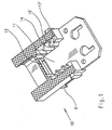
- FIG. 1 is a perspective view of a cut module housing 10 is shown.
- latching hooks 6 are integrally formed on the outer edges, by means of which the module housing, in addition to further module housings which can be lined up one behind the other, can be latched in a frame of a modular plug connector (not shown here).
- the module housing 10 has a plug-in area 11 and an opening 12 through which a plug-in connector 1 protrudes to contact with a mating connector.
- a connector 1 used in this case is supplied together with an electrical cable 8 as already ready-made cable connection.
- the cable connection is formed from the connector 1, consisting of a connector housing 2, with a plug-in area 3 and the connected cable 4.
- the plug-in area 3 is supplied by the various connector manufacturers in a certain range, but with different dimensions, so that only a variably designed locking device is expedient for the fixation of a connector.
- a locking device is provided in the plug-in region 11 of the module housing, wherein in the narrow sides of the module housing in each case at least one detent spring 16 '- reaching into a recess 14 in the bottom of the module housing - is formed.
- two successive staggered, integrally formed detent springs 16 ' are provided on both sides of the plug-in area, which are aligned with their ends 17', approximately at an angle of 45 ° from the wall in the insertion direction into the plug-in area 11.
- the spring ends 17 'slide When inserting the connector housing 2 in the module housing 10, the spring ends 17 'slide initially along the narrow sides of the housing in the plug-in area 5, but unfold a wedging effect when pulling back the connector.
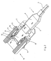
- Fig. 2 is shown in a perspective view of a connector 1, which is already partially inserted into a module housing 10, which is shown in a section.
- a variant of the in Fig. 1 Locking device shown provided, wherein in the plug-in area 11 two opposing spring elements 15 are arranged, each with a detent spring 16, or with the end 17 in the plug-in area 11 have.
- the spring elements 15 are fixed with their ends 19 in slots 13 and are used by a one-sided executed insertion opening 14 in the module housing captive.
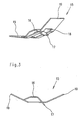
- the spring element 15 is shown, which has a slight U-shaped curvature and protrudes from the center of a three-sided release latching spring 16.
- the detent spring is first formed into the curvature of the spring element, but projects with the spring end 17 against the curvature of the cut-out opening 18. The curvature is required to hold the locking element with a certain tension within the slots 13 in the module 10.
- the detent springs 16 For disassembly of the plug connector, however, the detent springs 16 must be bent back from the outside, in which by inserting a flat Tool in the bottom opening 14 in the Modulgeophuse10 the locking springs are intimidzubiegen.
- this effort is justified in quite as these connectors are integrated within a system plug equipped with a plurality of modular plug and are usually equipped only when installing a new system, otherwise separated by a separation of the two halves of the module plug and the connectors held therein are.
Landscapes
- Details Of Connecting Devices For Male And Female Coupling (AREA)
- Connector Housings Or Holding Contact Members (AREA)
- Coupling Device And Connection With Printed Circuit (AREA)
Claims (5)
- Dispositif de fixation d'un boîtier (2) de connecteur à fiches d'un connecteur à fiches (1) dans un boîtier de module (10) isolant d'une fiche mâle de module,
caractérisé en ce que
une zone d'enfichage (11) est prévue dans le boîtier de module (10),
et en ce qu'au moins un élément ressort avec un ressort d'arrêt (16, 16') intégré est agencé dans la zone d'enfichage (11),
et en ce que l'extrémité de ressort (17, 17') du ressort d'arrêt (16, 16'), orientée selon le sens d'enfichage, fait saillie dans la zone d'enfichage (11),
de telle sorte que lors de l'enfichage du boîtier (2) de connecteur à fiches dans le boîtier de module (10), les extrémités de ressort (17, 17') glissent tout d'abord le long des petits côtés du boîtier dans la zone d'enfichage (5) et développent un effet de calage lors d'un mouvement de retrait du connecteur à fiche. - Dispositif selon la revendication 1, caractérisé en ce que
le ressort d'arrêt (16') est moulé avec le boîtier de module (10) dans la zone d'enfichage (11). - Dispositif selon la revendication 1, caractérisé en ce que
le ressort d'arrêt (16) est intégré dans un élément ressort (15) plat en forme de U, l'extrémité (17) du ressort d'arrêt faisant saillie hors de l'élément ressort à l'encontre de la forme en U. - Dispositif selon les revendications 1 et 3, caractérisé en ce que
l'élément ressort (15) est inséré dans des fentes (13) dans la zone d'enfichage (11) du boîtier de module (10). - Dispositif selon la revendication 1, caractérisé en ce que
au moins une ouverture (14) est prévue dans la zone de fond du boîtier de module.
Priority Applications (1)
| Application Number | Priority Date | Filing Date | Title |
|---|---|---|---|
| EP12003590.2A EP2528169B1 (fr) | 2004-05-07 | 2005-03-03 | Despositif de fixation d' un connecteur à fiche |
Applications Claiming Priority (2)
| Application Number | Priority Date | Filing Date | Title |
|---|---|---|---|
| DE202004007300U | 2004-05-07 | ||
| DE202004007300U DE202004007300U1 (de) | 2004-05-07 | 2004-05-07 | Vorrichtung zur Befestigung eines Steckverbinders |
Related Child Applications (1)
| Application Number | Title | Priority Date | Filing Date |
|---|---|---|---|
| EP12003590.2 Division-Into | 2012-05-08 |
Publications (2)
| Publication Number | Publication Date |
|---|---|
| EP1594196A1 EP1594196A1 (fr) | 2005-11-09 |
| EP1594196B1 true EP1594196B1 (fr) | 2012-08-01 |
Family
ID=33305363
Family Applications (2)
| Application Number | Title | Priority Date | Filing Date |
|---|---|---|---|
| EP05004623A Active EP1594196B1 (fr) | 2004-05-07 | 2005-03-03 | Despositif de fixation d' un connecteur à fiche |
| EP12003590.2A Active EP2528169B1 (fr) | 2004-05-07 | 2005-03-03 | Despositif de fixation d' un connecteur à fiche |
Family Applications After (1)
| Application Number | Title | Priority Date | Filing Date |
|---|---|---|---|
| EP12003590.2A Active EP2528169B1 (fr) | 2004-05-07 | 2005-03-03 | Despositif de fixation d' un connecteur à fiche |
Country Status (7)
| Country | Link |
|---|---|
| US (2) | US8038463B2 (fr) |
| EP (2) | EP1594196B1 (fr) |
| JP (1) | JP4124779B2 (fr) |
| CN (1) | CN1694313A (fr) |
| CA (1) | CA2506922C (fr) |
| DE (1) | DE202004007300U1 (fr) |
| ES (2) | ES2450053T3 (fr) |
Families Citing this family (19)
| Publication number | Priority date | Publication date | Assignee | Title |
|---|---|---|---|---|
| DE202004007300U1 (de) | 2004-05-07 | 2004-10-14 | Harting Electric Gmbh & Co. Kg | Vorrichtung zur Befestigung eines Steckverbinders |
| DE202006009187U1 (de) | 2006-04-22 | 2007-08-30 | Weidmüller Interface GmbH & Co. KG | Adaptergehäuse zur Aufnahme eines Stecker- oder Buchsenteiles |
| EP2151765A1 (fr) * | 2008-07-29 | 2010-02-10 | Teldat S.A. | Bloqueur de connexion USB et dispositif antivol |
| JP2010040317A (ja) * | 2008-08-05 | 2010-02-18 | Toshiba Tec Corp | Usbコネクタカバー |
| US7878865B2 (en) * | 2009-06-08 | 2011-02-01 | International Business Machines Corporation | Locking connector for engaging a USB receptacle |
| EP2302744B1 (fr) * | 2009-09-24 | 2012-06-20 | Tyco Electronics France SAS | Douille électrique avec élément de soutien, prise électrique dotée d'une poche de déformation et ensemble de prise doté d'au moins une douille et une prise, et procédé de connexion de prise et de douille |
| CN101719206B (zh) * | 2009-12-16 | 2012-12-19 | 成都市华为赛门铁克科技有限公司 | Usb设备的保护装置 |
| TWI492460B (zh) * | 2010-08-18 | 2015-07-11 | Hon Hai Prec Ind Co Ltd | 連接器 |
| CN101950882B (zh) * | 2010-09-13 | 2012-07-25 | 文创太阳能(福建)科技有限公司 | 便捷式电器接线的卡固装置 |
| JP5653202B2 (ja) * | 2010-12-16 | 2015-01-14 | モレックス インコーポレイテドMolex Incorporated | コネクタ |
| CN102842809B (zh) * | 2011-06-25 | 2016-06-08 | 富士康(昆山)电脑接插件有限公司 | 线缆连接器组件 |
| WO2013116463A1 (fr) * | 2012-01-31 | 2013-08-08 | Invue Security Products Inc. | Cordon adaptateur d'alimentation ayant un connecteur de verrouillage |
| US9559479B2 (en) | 2013-10-11 | 2017-01-31 | Stmicroelectronics, Inc. | Angled connector for connecting two devices and having a fastening device |
| US9683393B2 (en) | 2014-10-31 | 2017-06-20 | ACCO Brands Corporation | System for physically securing an electronic device |
| CN104577493B (zh) * | 2014-12-26 | 2016-12-07 | 广东雅联科技股份有限公司 | 一种用于usb连接器的后胶芯模组结构 |
| US9831603B2 (en) * | 2015-11-20 | 2017-11-28 | Joseph Balest | Device for stabilizing a power cord |
| CA191988S (en) * | 2019-06-21 | 2021-12-16 | Nicoventures Holdings Ltd | Charging cradle |
| JP7413550B2 (ja) * | 2020-02-10 | 2024-01-15 | アイティーティー マニュファクチャーリング エンタープライジズ エルエルシー | マルチコネクタアセンブリ |
| WO2024085769A1 (fr) * | 2022-10-17 | 2024-04-25 | Lambda Networks As | Dispositif de relâchement de ressort pour mettre en oeuvre une opération de relâchement d'un connecteur |
Family Cites Families (53)
| Publication number | Priority date | Publication date | Assignee | Title |
|---|---|---|---|---|
| US2143562A (en) * | 1936-09-14 | 1939-01-10 | Kros Josef | Securing means for the screwthreaded bases of electric current leads |
| US3215969A (en) * | 1962-03-02 | 1965-11-02 | Swivelier Company Inc | Means for securing fixtures to busway |
| BE831874A (fr) | 1974-07-31 | 1976-01-29 | Connecteurs electriques | |
| US3993394A (en) | 1974-07-31 | 1976-11-23 | Raychem Corporation | Connector half having connector wafer retained therein |
| US4764130A (en) | 1983-02-07 | 1988-08-16 | Amp Incorporated | Electrical connector having terminal housing retaining member |
| GB8408614D0 (en) | 1984-04-04 | 1984-05-16 | Hewlett Packard Ltd | Electrical connectors |
| US4927388A (en) | 1989-09-29 | 1990-05-22 | Amp Incorporated | Electrical connector shell assembly and module retention clip |
| US5199897A (en) * | 1990-03-15 | 1993-04-06 | Japan Aviation Electronics Industry, Ltd. | Electrical connectors |
| US5254013A (en) * | 1990-04-25 | 1993-10-19 | Hirose Electric Co., Ltd. | Push-pull lock connector |
| KR930002630Y1 (ko) * | 1990-07-11 | 1993-05-17 | 삼성전자 주식회사 | 컴퓨터용 주변기기의 고정 구조체 |
| JP2836705B2 (ja) * | 1990-10-29 | 1998-12-14 | 矢崎総業株式会社 | 電気接続用コネクタハウジングロック |
| US5197901A (en) * | 1990-10-30 | 1993-03-30 | Japan Aviation Electronics Industry, Limited | Lock-spring and lock-equipped connector |
| US5178557A (en) * | 1990-10-31 | 1993-01-12 | Japan Aviation Electronics Industry, Limited | Electric connector having symmetric locking blocks at opposite ends |
| US5178556A (en) * | 1991-10-24 | 1993-01-12 | Advanced-Connectek Inc. | Computer plug connector fastening mechanism |
| JP2903193B2 (ja) * | 1992-02-26 | 1999-06-07 | 三菱電線工業株式会社 | コネクタのロック機構 |
| US5545052A (en) * | 1992-08-19 | 1996-08-13 | Honda Tsushin Kogyo Kabushiki Kaisha | Electrical connector |
| US5383794A (en) * | 1993-07-16 | 1995-01-24 | The Whitaker Corporation | Latch actuator for a connector |
| FR2717623B1 (fr) * | 1994-03-15 | 1996-06-07 | Ernest Pizon | Connecteur pour câble coaxial. |
| US5558534A (en) * | 1994-06-30 | 1996-09-24 | The Whitaker Corporation | Self sacrificing latching system |
| JP2904024B2 (ja) * | 1994-08-08 | 1999-06-14 | 住友電装株式会社 | 電気自動車のチャージ用コネクタ |
| DE19500102C2 (de) * | 1995-01-04 | 1999-09-30 | Itt Cannon Gmbh | Verriegelungsvorrichtung für einen Steckverbinder |
| US5599207A (en) * | 1995-04-24 | 1997-02-04 | Lai; Chin T. | Electrical connector with improved mounting device |
| US5616045A (en) * | 1995-07-14 | 1997-04-01 | Augat Inc. | Squib connector for automotive air bag assembly |
| US5749746A (en) * | 1995-09-26 | 1998-05-12 | Hon Hai Precision Ind. Co., Ltd. | Cable connector structure |
| US6139350A (en) * | 1996-05-20 | 2000-10-31 | Siemens Aktiengesellschaft | Latching system for a pin-and-socket connector |
| US5997333A (en) * | 1996-08-09 | 1999-12-07 | Sumitomo Wiring Systems, Ltd. | Locking device for high-voltage cable connectors |
| WO1999031539A1 (fr) * | 1997-12-17 | 1999-06-24 | Sumitomo Electric Industries, Ltd. | Tige de guidage pour connecteurs de fibres optiques et fiche de connecteur pour fibres optiques |
| KR100543487B1 (ko) | 1998-05-27 | 2006-01-20 | 타이코 일렉트로닉스 코포레이션 | 분리식 셸 및 보유 클립을 갖는 전기 커넥터 및 전기커넥터 조립 방법 |
| GB2337877B (en) * | 1998-05-28 | 2000-10-04 | Yazaki Corp | Connector fitting structure |
| US6083030A (en) * | 1998-09-23 | 2000-07-04 | Osram Sylvania Inc. | Connector latch |
| TW389411U (en) * | 1998-12-31 | 2000-05-01 | Hon Hai Prec Ind Co Ltd | Electrical connector |
| US6312277B1 (en) * | 1999-01-27 | 2001-11-06 | Cardell Corporation | Connector position assurance device for a connector |
| US6394842B1 (en) * | 1999-04-01 | 2002-05-28 | Fujitsu Takamisawa Component Limited | Cable connecting structure |
| US6325653B1 (en) * | 1999-07-15 | 2001-12-04 | Kabushiki Kaisha Yokowo | Terminal connecting apparatus for storage device |
| US6123575A (en) * | 1999-07-30 | 2000-09-26 | Huang; Wayne | Electrical card connector with mixed latching means |
| JP3611754B2 (ja) * | 1999-08-24 | 2005-01-19 | 株式会社ヨコオ | アンテナ構造 |
| DE19958841A1 (de) * | 1999-12-07 | 2001-06-21 | Bjb Gmbh & Co Kg | Lampenfassung |
| DE20000160U1 (de) * | 2000-01-07 | 2000-03-30 | Leopold Kostal GmbH & Co KG, 58507 Lüdenscheid | Elektrisches Steckverbindungsteil |
| TW461615U (en) * | 2000-02-22 | 2001-10-21 | Hon Hai Prec Ind Co Ltd | Electrical connector |
| FR2806218B1 (fr) * | 2000-03-10 | 2004-09-10 | Framatome Connectors Int | Connecteur d'entree/sortie du type fiche |
| US20020048986A1 (en) * | 2000-07-17 | 2002-04-25 | Lewis Richard Lee | Electrical connector with discrete sections |
| NL1015918C2 (nl) * | 2000-08-11 | 2002-02-12 | Fci Mechelen N V | Kabelconnector en kit voor het maken van een kabelconnector. |
| JP3687537B2 (ja) | 2000-12-25 | 2005-08-24 | 住友電装株式会社 | 分割コネクタ |
| DE10104288C1 (de) | 2001-01-30 | 2002-04-04 | Karl Lumberg Gmbh & Co Kg | Elektrische Steckverbindung |
| US6619976B2 (en) * | 2001-04-13 | 2003-09-16 | Hewlett-Packard Development Company, Lp. | Apparatus and method for cable connection retention |
| JP3887692B2 (ja) * | 2001-08-09 | 2007-02-28 | 住友電装株式会社 | コネクタ |
| US6491542B1 (en) * | 2002-01-16 | 2002-12-10 | Yazaki North America | Combined connection and terminal position assurance structure for vehicle wiring connectors |
| US6695636B2 (en) * | 2002-01-23 | 2004-02-24 | Tyco Electronics Corporation | Lockable electrical connector |
| US6848931B2 (en) * | 2002-07-19 | 2005-02-01 | Andrew Corporation | Quick attachment SMA connector |
| US6589066B1 (en) * | 2002-07-30 | 2003-07-08 | Hon Hai Precision Ind. Co., Ltd. | Electrical connector having a latch mechanism |
| US6776658B2 (en) | 2002-08-06 | 2004-08-17 | Hon Hai Precision Ind. Co., Ltd. | Cable end connector |
| DE202004007300U1 (de) | 2004-05-07 | 2004-10-14 | Harting Electric Gmbh & Co. Kg | Vorrichtung zur Befestigung eines Steckverbinders |
| US7374349B2 (en) * | 2004-09-10 | 2008-05-20 | Intel Corporation | Optical fiber connector |
-
2004
- 2004-05-07 DE DE202004007300U patent/DE202004007300U1/de not_active Expired - Lifetime
-
2005
- 2005-03-03 EP EP05004623A patent/EP1594196B1/fr active Active
- 2005-03-03 ES ES12003590.2T patent/ES2450053T3/es active Active
- 2005-03-03 ES ES05004623T patent/ES2390460T3/es active Active
- 2005-03-03 EP EP12003590.2A patent/EP2528169B1/fr active Active
- 2005-04-19 CN CNA2005100652896A patent/CN1694313A/zh active Pending
- 2005-05-02 US US11/120,020 patent/US8038463B2/en active Active
- 2005-05-09 CA CA002506922A patent/CA2506922C/fr not_active Expired - Fee Related
- 2005-05-09 JP JP2005136355A patent/JP4124779B2/ja not_active Expired - Fee Related
-
2011
- 2011-10-14 US US13/274,115 patent/US8257104B2/en active Active
Also Published As
| Publication number | Publication date |
|---|---|
| DE202004007300U1 (de) | 2004-10-14 |
| US8038463B2 (en) | 2011-10-18 |
| CN1694313A (zh) | 2005-11-09 |
| CA2506922C (fr) | 2009-07-28 |
| CA2506922A1 (fr) | 2005-11-07 |
| EP1594196A1 (fr) | 2005-11-09 |
| US8257104B2 (en) | 2012-09-04 |
| ES2390460T3 (es) | 2012-11-13 |
| US20120034811A1 (en) | 2012-02-09 |
| EP2528169A1 (fr) | 2012-11-28 |
| EP2528169B1 (fr) | 2013-12-11 |
| JP2005322654A (ja) | 2005-11-17 |
| US20050250369A1 (en) | 2005-11-10 |
| JP4124779B2 (ja) | 2008-07-23 |
| ES2450053T3 (es) | 2014-03-21 |
Similar Documents
| Publication | Publication Date | Title |
|---|---|---|
| EP1594196B1 (fr) | Despositif de fixation d' un connecteur à fiche | |
| EP1796225B1 (fr) | Dispositif pour un câble de connexion coulissant axialement dans un boîtier de connecteur | |
| DE102017113875B3 (de) | Elektrischer Stecker mit einem Schutzleiterkontakt und damit einstückig ausgebildeten Schutzleiterverbindungselement zur Erdung von Außenteilen | |
| DE20007001U1 (de) | Stecker mit einer Hülse | |
| EP3329558B1 (fr) | Connecteur électrique | |
| EP2769441B1 (fr) | Connecteur | |
| DE102006004782B4 (de) | Verfahren zur Herstellung einer Verrastungsvorrichtung für einen elektrischen Kontakt in einem Steckverbinder | |
| EP3375046A1 (fr) | Borne de branchement électrique | |
| DE10227016A1 (de) | Elektrischer Steckverbinder | |
| EP2736124A1 (fr) | Connecteur à fiche électrique avec un corps isolant amovible par outil enclenché du côté enfichage | |
| DE69310439T2 (de) | Verriegelbarer elektrischer Verbinderanordnung | |
| DE102005053566A1 (de) | Steckerstift mit Federklemme | |
| DE102007005737A1 (de) | Kopfstützensystem für einen Fahrzeugsitz | |
| DE102017124670A1 (de) | Elektrische Steckverbindung | |
| DE102010024525A1 (de) | Elektrischer Buchsenkontakt | |
| DE202009005366U1 (de) | Industrie-Steckvorrichtung | |
| EP2054973A1 (fr) | Connecteur mâle avec verrouillage secondaire pour une connexion électrique enfichable | |
| EP3143320A1 (fr) | Unité de raccordement destinée à un dispositif d'accouplement, en particulier à un raccord multiple | |
| EP3111518A1 (fr) | Connecteur | |
| DE10326834B4 (de) | Steckverbinder | |
| EP1411596B1 (fr) | Connecteur à fiche ayant un élément de retenue | |
| DE19747115A1 (de) | Elektrische Steckverbinderanordnung und elektrischer Kontakt | |
| DE69706858T2 (de) | Elektrischer verbinder mit einstuckigem sekundaren verriegelungselement | |
| DE102012105901A1 (de) | Zugentlastungseinheit für einen elektrischen Steckverbinder und Gerätegehäuse | |
| DE102022133138A1 (de) | Steckverbindereinsatz für einen elektrischen Steckverbinder |
Legal Events
| Date | Code | Title | Description |
|---|---|---|---|
| PUAI | Public reference made under article 153(3) epc to a published international application that has entered the european phase |
Free format text: ORIGINAL CODE: 0009012 |
|
| AK | Designated contracting states |
Kind code of ref document: A1 Designated state(s): AT BE BG CH CY CZ DE DK EE ES FI FR GB GR HU IE IS IT LI LT LU MC NL PL PT RO SE SI SK TR |
|
| AX | Request for extension of the european patent |
Extension state: AL BA HR LV MK YU |
|
| 17P | Request for examination filed |
Effective date: 20060203 |
|
| AKX | Designation fees paid |
Designated state(s): CH DE ES FR GB IT LI |
|
| 17Q | First examination report despatched |
Effective date: 20110916 |
|
| GRAP | Despatch of communication of intention to grant a patent |
Free format text: ORIGINAL CODE: EPIDOSNIGR1 |
|
| GRAS | Grant fee paid |
Free format text: ORIGINAL CODE: EPIDOSNIGR3 |
|
| GRAA | (expected) grant |
Free format text: ORIGINAL CODE: 0009210 |
|
| AK | Designated contracting states |
Kind code of ref document: B1 Designated state(s): CH DE ES FR GB IT LI |
|
| REG | Reference to a national code |
Ref country code: GB Ref legal event code: FG4D Free format text: NOT ENGLISH |
|
| REG | Reference to a national code |
Ref country code: CH Ref legal event code: EP |
|
| REG | Reference to a national code |
Ref country code: DE Ref legal event code: R096 Ref document number: 502005012950 Country of ref document: DE Effective date: 20120927 |
|
| REG | Reference to a national code |
Ref country code: ES Ref legal event code: FG2A Ref document number: 2390460 Country of ref document: ES Kind code of ref document: T3 Effective date: 20121113 |
|
| PLBE | No opposition filed within time limit |
Free format text: ORIGINAL CODE: 0009261 |
|
| STAA | Information on the status of an ep patent application or granted ep patent |
Free format text: STATUS: NO OPPOSITION FILED WITHIN TIME LIMIT |
|
| 26N | No opposition filed |
Effective date: 20130503 |
|
| REG | Reference to a national code |
Ref country code: DE Ref legal event code: R097 Ref document number: 502005012950 Country of ref document: DE Effective date: 20130503 |
|
| REG | Reference to a national code |
Ref country code: FR Ref legal event code: PLFP Year of fee payment: 11 |
|
| REG | Reference to a national code |
Ref country code: FR Ref legal event code: PLFP Year of fee payment: 12 |
|
| REG | Reference to a national code |
Ref country code: FR Ref legal event code: PLFP Year of fee payment: 13 |
|
| PGFP | Annual fee paid to national office [announced via postgrant information from national office to epo] |
Ref country code: CH Payment date: 20170314 Year of fee payment: 13 |
|
| PGFP | Annual fee paid to national office [announced via postgrant information from national office to epo] |
Ref country code: ES Payment date: 20170214 Year of fee payment: 13 |
|
| REG | Reference to a national code |
Ref country code: FR Ref legal event code: PLFP Year of fee payment: 14 |
|
| REG | Reference to a national code |
Ref country code: CH Ref legal event code: PL |
|
| PG25 | Lapsed in a contracting state [announced via postgrant information from national office to epo] |
Ref country code: CH Free format text: LAPSE BECAUSE OF NON-PAYMENT OF DUE FEES Effective date: 20180331 Ref country code: LI Free format text: LAPSE BECAUSE OF NON-PAYMENT OF DUE FEES Effective date: 20180331 |
|
| REG | Reference to a national code |
Ref country code: ES Ref legal event code: FD2A Effective date: 20190904 |
|
| PG25 | Lapsed in a contracting state [announced via postgrant information from national office to epo] |
Ref country code: ES Free format text: LAPSE BECAUSE OF NON-PAYMENT OF DUE FEES Effective date: 20180304 |
|
| P01 | Opt-out of the competence of the unified patent court (upc) registered |
Effective date: 20230603 |
|
| PGFP | Annual fee paid to national office [announced via postgrant information from national office to epo] |
Ref country code: DE Payment date: 20240328 Year of fee payment: 20 Ref country code: GB Payment date: 20240319 Year of fee payment: 20 |
|
| PGFP | Annual fee paid to national office [announced via postgrant information from national office to epo] |
Ref country code: IT Payment date: 20240321 Year of fee payment: 20 Ref country code: FR Payment date: 20240327 Year of fee payment: 20 |