EP2302744B1 - Douille électrique avec élément de soutien, prise électrique dotée d'une poche de déformation et ensemble de prise doté d'au moins une douille et une prise, et procédé de connexion de prise et de douille - Google Patents
Douille électrique avec élément de soutien, prise électrique dotée d'une poche de déformation et ensemble de prise doté d'au moins une douille et une prise, et procédé de connexion de prise et de douille Download PDFInfo
- Publication number
- EP2302744B1 EP2302744B1 EP09290724A EP09290724A EP2302744B1 EP 2302744 B1 EP2302744 B1 EP 2302744B1 EP 09290724 A EP09290724 A EP 09290724A EP 09290724 A EP09290724 A EP 09290724A EP 2302744 B1 EP2302744 B1 EP 2302744B1
- Authority
- EP
- European Patent Office
- Prior art keywords
- plug
- socket
- mating direction
- latching
- receiving section
- Prior art date
- Legal status (The legal status is an assumption and is not a legal conclusion. Google has not performed a legal analysis and makes no representation as to the accuracy of the status listed.)
- Active
Links
- 238000000034 method Methods 0.000 title description 21
- 230000013011 mating Effects 0.000 claims description 99
- 238000006073 displacement reaction Methods 0.000 claims description 61
- 238000007789 sealing Methods 0.000 claims description 14
- 238000007373 indentation Methods 0.000 claims description 8
- 239000004020 conductor Substances 0.000 claims description 7
- 230000003313 weakening effect Effects 0.000 description 8
- 210000000887 face Anatomy 0.000 description 6
- 238000003780 insertion Methods 0.000 description 6
- 230000037431 insertion Effects 0.000 description 6
- 230000000630 rising effect Effects 0.000 description 2
- 239000000243 solution Substances 0.000 description 2
- 230000036461 convulsion Effects 0.000 description 1
- 230000003247 decreasing effect Effects 0.000 description 1
- 239000000428 dust Substances 0.000 description 1
- 238000001746 injection moulding Methods 0.000 description 1
- 239000011810 insulating material Substances 0.000 description 1
- 230000003993 interaction Effects 0.000 description 1
- 210000001331 nose Anatomy 0.000 description 1
- 230000000087 stabilizing effect Effects 0.000 description 1
- 238000012795 verification Methods 0.000 description 1
Images


Classifications
-
- H—ELECTRICITY
- H01—ELECTRIC ELEMENTS
- H01R—ELECTRICALLY-CONDUCTIVE CONNECTIONS; STRUCTURAL ASSOCIATIONS OF A PLURALITY OF MUTUALLY-INSULATED ELECTRICAL CONNECTING ELEMENTS; COUPLING DEVICES; CURRENT COLLECTORS
- H01R13/00—Details of coupling devices of the kinds covered by groups H01R12/70 or H01R24/00 - H01R33/00
- H01R13/62—Means for facilitating engagement or disengagement of coupling parts or for holding them in engagement
- H01R13/627—Snap or like fastening
- H01R13/6271—Latching means integral with the housing
-
- H—ELECTRICITY
- H01—ELECTRIC ELEMENTS
- H01R—ELECTRICALLY-CONDUCTIVE CONNECTIONS; STRUCTURAL ASSOCIATIONS OF A PLURALITY OF MUTUALLY-INSULATED ELECTRICAL CONNECTING ELEMENTS; COUPLING DEVICES; CURRENT COLLECTORS
- H01R13/00—Details of coupling devices of the kinds covered by groups H01R12/70 or H01R24/00 - H01R33/00
- H01R13/46—Bases; Cases
- H01R13/52—Dustproof, splashproof, drip-proof, waterproof, or flameproof cases
- H01R13/5219—Sealing means between coupling parts, e.g. interfacial seal
- H01R13/5221—Sealing means between coupling parts, e.g. interfacial seal having cable sealing means
Definitions
- the present invention relates to an electrical socket with a housing that is adapted to be mated with an electrical plug in a mating direction, the housing comprising a hollow and essentially cylindrical receiving section for receiving the plug, with at least one actuating zone that is adapted to be manually, elastically deformed in an actuating direction running perpendicular to the mating direction and towards the interior of the housing, and with a displacement zone, which comprises a latching element that faces in the mating direction, the displacement zone being adapted to move from a initial position to a deflected position in a radial direction running perpendicular to the mating direction and away from the interior of the housing when the at least one actuating zone is deformed in the actuating direction.
- the present invention relates to an electrical plug with an essentially cylindrical plug member, the plug member extending in a mating direction and being adapted to be mated with an electrical socket, the plug member comprising at least one outer wall guiding section, which extends in the mating direction, and with a latching member, which faces against the mating direction and at least section-wise projects from the plug member in a radial direction perpendicular to the mating direction.
- the present invention relates to a plug assembly with at least one plug and at least one socket, the socket being adapted to be mated with the plug.
- connection assembly described in this document comprises a socket with a cylindrical housing and a receiving section, the receiving section extending in the mating direction and having an elliptical footprint.
- connection arrangement of the German patent DE 41 19 122 C2 differs from the above assembly by an elastically deformable receiving section, which comprises an octagonal base.
- an object underlying the invention is to provide a socket and a plug for a plug connection as well as a method for connecting a plug and a socket with an increased security of connection.
- the receiving section comprises at least one supporting element, which is arranged on an inner surface of the receiving section.
- the object is achieved according to the invention in that the plug member comprises at least one deformation indentation that extends into the mating direction and that is located before the guiding section in the mating direction.
- the object is achieved according to the present invention in that the socket and the plug are configured according to the invention, wherein the at least one supporting surface section rests on the plug member at least when the plug and the socket are partly mated in the mating direction.
- the supporting element may project into the interior of the receiving section and comprise at least one supporting surface section facing to the interior of the receiving section, the actuating zone being arranged between the displacement zone and the supporting element.
- the supporting element can be arranged in the area of the actuating zone, preventing an inappropriate deformation of the actuating zone.
- the plug member can raise the receiving section via the supporting surface, thereby avoiding an inappropriate deformation of the receiving section. Furthermore, the supporting elements can reinforce the receiving section against inappropriate deformation. Also, the arrangement of the actuating zone provides for an easy handling of the mated connection, e.g. during the unmating procedure.
- the receiving section can have a polygonal footprint, the footprint or cross-section comprising at least three, and particularly, at least five or even at least eight or more corners.
- an elliptical or a cylindrical cross-section of the housing is especially advantageous.
- the socket can be adapted to be repeatedly mated and latched or unlatched with the plug. Therefore, at least the receiving section can be elastically deformable transverse to the mating direction. Also, the plug can be adapted to be repeatedly inserted into and removed from the socket.
- a method for connecting a plug and a socket wherein a plug member of the plug can be inserted into a receiving section of the socket in a mating direction may be provided.
- the connecting may proceed in three consecutive phases, which comprise the steps of:
- the socket may comprise at least one further actuating zone and the actuating zones may be arranged opposite of each other. If the two actuating zones are flanking the displacement zone and if they are pressed towards the interior of the receiving section at the same time, the amplitude of the resulting movement of the displacement zone and the latching element increases. Furthermore, the resulting movement is further directed away from the socket and leads less into a tangential direction of the receiving section.
- the size of the latching element which may be shaped as a latching wall, extending in a radial direction as well as the latching overlap of the latching element and the latching member of the plug can be enlarged, leading to an increased security of the locked or latched plug connection.
- the actuating zones and the supporting elements can be arranged symmetrically around the displacement zone. Deforming the actuating zones in an equal amount towards the interior of the housing then leads to a movement of the displacement zone in the radial direction, which extends perpendicular to the mating direction and away from the receiving section or its longitudinal axis. Influences of actuating zones and supporting elements that are asymmetrically arranged around the displacement zone and which may lead to a movement of the displacement zone in a direction that is tilted with respect to the radial direction into the tangential direction, is at least minimized by this measure. The overlap of the latching element and member can be further increased.
- the socket can comprise at least one additional supporting element and the supporting elements can be arranged at a maximum distance to each other on the inner surface of the receiving section.
- the supporting elements can be located in a plane which extends in the mating direction and along the longitudinal axis of the essentially cylindrical housing.
- the supporting elements can be arranged above the plane, i.e. closer to the latching elements.
- the two supporting elements can be located below the plane or further away from the latching element.
- the amplitude of the displacement of the latching element caused by the deformation of the actuating zones is increased compared to the above two alternatives.
- the actuating zones can be more easily deformed, which may result in an unexpected unlocking of the plug and the socket.
- the plug needs to be secured against unintentional movements in or against the radial direction or shall be supported opposite to the latching member, yet another supporting element can be arranged opposite to the displacement zone.
- This embodiment with three supporting elements is especially advantageous, as the three supporting elements act as a 3-jaw chuck, optimally fixing the position of the plug in the receiving section and in the radial direction.
- the socket can be provided with the at least one supporting element and especially with only this supporting element, which may essentially extend over half of the inner surface of the receiving section in a circumferential direction.
- the at least one supporting element can be arranged opposite to the displacement zone.
- the at least one supporting element may be shaped as a channel with an essential semi-circular footprint or cross-section. This channel is optimally shaped for receiving the plug member and for guiding it in the mating procedure.
- the above embodiments of the supporting elements allow for a precise guidance of the movement of the plug inside the receiving section in and against the mating direction, as at least parts of the outer wall guiding section rest on the supporting surface sections of the supporting elements when the plug is at least partially inserted into the receiving section. Furthermore, forces acting onto areas of the receiving section outside of the actuating sections are led into the plug member, on which the receiving section rests via the supporting surfaces.
- a conductor arrangement with at least one electrical conductor housed in a sealing jacket can be arranged inside the housing.
- the sealing jacket may be shaped with at least one sealing rib, which can extend around the circumference of the jacket and which may indicate away from the conductor.
- Such a conductor arrangement permits a sealed and, for instance, dust or waterproof plug assembly between the socket and the plug.
- the plug may comprise at least one further deformation pocket, which can essentially be arranged abreast the outer wall guiding section in the mating direction.
- the outer wall guiding section and the deformation pocket can be arranged after each other in a circumferential direction of the plug member.
- the deformation pocket can provide for a free deformation space, in which the adjacent deformation zone canevade, allowing for a small deformation of the displacement zones during the first deformation phase of the connecting procedure, reducing the force necessary for the connection of the plug and the socket.
- the deformation zone can be further deformed than without the deformation pocket, resulting in a larger possible displacement zone.
- the plug comprises at least one further deformation pocket.
- the latching member may be arranged between the two deformation pockets and the outer wall guiding section can at least section-wise be arranged opposite to the latching member.
- the two actuating zones can be shaped to be equally deformed towards the interior of the receiving section and thus, each evade into one of the deformation pockets in equal measure.
- the latching member can be arranged on a latching bar, which can extend in the mating direction and which may protrude from the plug member transversely to the mating direction.
- the latching bar may comprise a leading inclined displacement surface, which may indicate in the mating direction and away from the plug member and which can be arranged behind the deformation pocket in the mating direction.
- the displacement surface interacts with a latching bridge, which is equipped with the latching element of the socket.
- a guiding recess which extends in and which widens against the mating direction, may align the latching bar, the bar being slightly narrower in the circumferential direction than the recess.
- the force necessary for further inserting the plug into the socket increases in proportion to the depth of insertion and reaches a maximum shortly before the latching element has reached the deflected position.
- the receiving section is at least partially deformed and can even be stretched by the deflection of the latching element.
- the latching bar which may comprise a sliding surface that faces in the radial direction and runs parallel to the mating direction. Against the mating direction, the latching member can follow the sliding surface.
- the latching member can be part of the latching bar and may extend between the sliding surface and a holding surface.
- the holding surface can be level with the outer wall guiding section in the radial direction and may extend against the mating direction.
- the latching bar can slide on the sliding surface, which reduces the force necessary for further inserting the plug suddenly. Only frictional forces have to be overcome.
- the holding surface may end at a stop surface against the mating direction.
- This stop surface can be arranged opposite to and parallel with the latching member.
- the distance between the latching member and the stop surface can at least be equal to the length of the latching bridge in the mating direction.
- the deformation indention may essentially extend around the plug member in a circumferential direction.
- a plug assembly with such a plug can be equipped with a socket, the displacement zones of which extend essentially completely around the receiving section in the circular direction, resulting in an actuating zone with a maximum size possible.
- Such an actuating zone is especially easy to deform - the plug assembly being very easy to handle.
- the deformation indention can be discontinued in the circumferential direction by the latching bar and at least one of the supporting elements.
- the latching or locking security of the plug assembly may be influenced by such a design.
- the free actuating space can be arranged. This free actuating space enables a movement of the actuating zones towards the interior of the receiving section if the plug is partly mated with the socket.
- the displacement zone and the latching element of the socket can be displaced from their initial position into their deflected position perpendicular to the mating direction and in the radial direction, thus, away from the plug member, when at least one of the actuating zones and especially two of them is pressed in a direction transverse to the mating direction into the nearest deformation indention, thus, against the radial direction.
- the outer wall guiding section and the at least one deformation pocket may in another advantageous embodiment essentially be arranged consecutively in the mating direction.
- the at least one deformation pocket can essentially extend around the plug member in the circumferential direction.
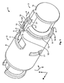
- a plug assembly 1 with an electrical socket 2 and an electrical plug with a plug member 3 configured according to the invention will be described with reference to Fig. 1 , which shows a schematic view of a first embodiment of the invention.
- the socket 2 and the plug member 3 are of an essentially cylindrical shape with a circular base.
- the socket 2 comprises a hollow receiving section 4, in which the plug member 3 can be inserted in a mating direction M.
- the socket 2 ends with a collar 5, which surrounds a receiving opening 6 of the receiving section 4.
- the collar 5 is shaped essentially circular and comprises a guiding recess 7 that extends in and widens against the mating direction M.
- the guiding recess 7 can be formed as a slot running in the mating direction M and being open against the mating direction M and towards the interior of the receiving section 4.
- a latching bridge 8 follows behind the guiding recess 7.
- the latching bridge 8 is shaped with a latching element 9 which faces in the mating direction M - the latching element 9 is shaped as a latching wall that runs essentially perpendicular to the mating direction M.
- the latching bridge 8 is shaped with a displacement wall 10, which faces against the mating direction M.
- the displacement wall 10 can be aligned perpendicular to the mating direction M. Alternatively, the displacement wall 10 can at least section-wise be tilted towards the interior of the receiving section 4.
- a weakening cut-out 11 follows the latching element 9.
- the weakening cut-out 11 extends in the mating direction M and in a circumferential direction C of the receiving section 4, which runs transversely to the mating direction M. Due to the weakening cut-out 11 and the generally flexible nature of the elastically deformable receiving section 4, a displacement zone 12, which extends in mating direction M between at least the latching element 9 and the displacement wall 10 can be more easily displaced in a radial direction R transverse to the mating direction M.
- further weakening cut-outs can be placed in a circumferential direction C next to the weakening cut-out 11.
- a second weakening cut-out 11' is shown, which is arranged abreast with the weakening cut-out 11 in the mating direction M.
- the plug member 3 is shown partially inserted into the socket 2 in a pre-locking position.
- the plug member 3 can be made out of one piece, e.g. by injection moulding, or it can comprise two or more shell pieces.
- the plug member 3 is designed with an outer wall guiding section 13, which is almost completely inserted into the receiving section 4 in mating direction M.
- the outer wall guiding section is shaped cylindrically and comprises an essentially circular cross-section transverse to the mating direction and fits snugly into the hollow receiving section 4 of the socket 2.
- the outer wall guiding section 13 as well as the inner wall of the hollow receiving section 4 can be designed with further guiding means like guiding recesses and guiding noses.
- plug member 3 In mating direction M before the outer wall guiding section 13, plug member 3 is shaped with a smaller cross-section compared to the outer wall guiding section 13.
- the diameter of the plug member 3 is especially reduced in the area of a deformation indention 14 that is formed by a setoff 15 in the plug member member 3.
- the outer wall of the plug member 3 sets back from the outer wall guiding section 13 towards the interior of the plug member 3 and against a radial direction R, which extends perpendicular to the mating direction M and away from the plug member 3.
- the indentation 14 extends in the mating direction M between the outer wall guiding section 13 and an end piece 16 of the plug member 3, which can continue in another part of the plug and through which electrical conductors like wires can reach. In the circumferential direction C, the indentation 14 extends almost round the plug member 3.
- the plug member 3 is provided with a latching bar 17 that extends in the mating direction M and that protrudes from the plug member 3 or its outer wall guiding section 13 perpendicular to the mating direction M.
- the latching bar 17 comprises a leading inclined displacement surface 18 that indicates in the mating direction M and away from the plug member 3.
- the displacement surface 18 abuts on the displacement wall 10 of the latching bridge 8.
- the guiding recess 7 is only a little wider than the latching bar 17, which is guided in the recess 7.
- the guiding recess 7 expands in its course.
- a latching member 19 faces against the mating direction M.
- the latching member 19 is part of the latching bar 17 and projects at least section-wise from the outer wall guiding section 13 of the plug member 3.
- a sliding surface 20 is placed, the sliding surface 20 running in the mating direction M and connecting the displacement surface 18 with the latching member 19.
- the sliding surface 20 forms a part of the latching bar 17 that is farthest away from the outer wall guiding section in the radial direction R.
- a stop surface 21 is arranged in a distance that is bigger than the length of the latching bridge 8 in the mating direction M.
- the stop surface 21 protrudes from the outer wall guiding section 13 at least as far as the latching member 19.
- Fig. 2 shows a further exemplary embodiment of the plug assembly 1 according to the invention in a cross-sectional view along a joint longitudinal axis E of the socket 2 and the plug member 3, the same reference signs being used for elements which correspond in function and structure to the elements of the exemplary embodiment of fig. 1 . for the sake of brevity, only the differences from the exemplary embodiment of Fig. 1 will be looked at.
- the plug assembly 1 comprises the electrical socket 2 and an electrical plug member 3'.
- the electrical plug member 3' differs from the plug member 3 of Fig. 1 in that the deformation indention does not completely extend around the plug member 3' in the circumferential direction C, and in that the plug member 3' does not comprise a stop surface 21. Rather, a section 13' of the outer wall guiding section 13, which is arranged opposite of the latching bar, extends until the end piece 16 of the plug member 3'.
- the counter contact 23 is part of a conductor arrangement 24, which also comprises a sealing jacket 25, in which the counter contact 23 and maybe further counter contacts are housed.
- the sealing jacket 25 is made of an electrical insulating material and comprises three sealing ribs 26 that are arranged after each other in the mating direction M and extend around the circumference of the jacket 25, thereby indicating away from the contact 23.
- the sealing ribs 26 can be elastically deformed.
- an inner sealing wall 27 sealingly contacts at least one of the sealing ribs 26.
- the outer wall guiding section 13 clings on an inner surface 28 of the receiving section 4, which can guide the plug member 3'.
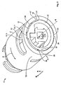
- Fig. 3 shows another embodiment of the plug assembly 1 in a schematic cross-sectional view, the sectional plane being arranged transversely to the mating direction M and abreast the displacement zone 12.
- Same reference signs are being used for elements, which correspond in function and structure to the elements of the exemplary embodiment of Figs. 1 or 2 .
- Figs. 1 or 2 For the sake of brevity, only the differences from the exemplary embodiment of Figs. 1 or 2 will be looked at.
- the plug assembly 1 comprises the plug member 3' shown in Fig. 2 and an electrical socket 2'.
- the plug member 3' is further inserted into the socket 2' in mating direction M compared to Figs. 1 and 2 . Still, the plug member 3' and the socket 2' are not latched yet.
- the latching bridge 8 has been displaced from its initial position shown in Figs. 1 and 2 into a deflected position perpendicular to the mating direction M and away from the plug member 3', as indicated by the arrow standing on the latching bridge 8 and indicating in the radial direction R. This displacement is caused by an interaction between the displacement wall 10 of the latching bridge 8 and the inclined displacement surface 18 during the insertion of the plug member 3'.
- the sliding surface 20 stands above the outer wall guiding section 13 in the radial direction R transverse to the mating direction M and holds the latching bridge 8 in the deflected position.
- each of the supporting elements 29 to 31 is shaped with a supporting surface section 32 to 34, that extends in the mating direction M at a constant distance to the inner surface 28 in the radial direction R.
- the supporting elements 29 to 31 extend at least in the area of the displacement zone 12 and guide the plug member 3'. Additionally, the supporting elements 29 to 31 prevent the receiving section 4 from unfavourable deformation.
- the supporting element 30 is arranged opposite to the latching member 19.
- the other two supporting elements 29, 31 are essentially arranged symmetrically to a plane extending through the latching member 19 and the axis E and opposite to each other at a maximum possible distance.
- the supporting elements 29 to 31 can be allocated differently. Furthermore, the amount of supporting elements 29 to 31 can differ from the displayed exemplary embodiment. For instance, there can only be the supporting element 30, which may be arranged opposite to the latching member 19 and which can extend over half of the inner guiding surface 28 of the receiving section 4 in the circumferential direction C. The supporting surface section 33 of such a supporting element 30 can span the supporting surface sections 32 and 34 of the supporting elements 29 and 31.
- the socket 2' can comprise only two supporting elements 29, 31, that are arranged symmetrical to the displacement zone 12 and at arbitrary positions. However, supporting elements 29 and 31 are especially advantageously placed if they are arranged at the maximum distance to each other or closer to the supporting element 30.
- deformation pockets 36, 37 are provided in the outer wall guiding section 13 of the plug member 3'.
- the deformation pockets 36, 37 are formed as cavities or impressions in the outer wall guiding section 13 and extend in the circumferential direction C between the supporting elements 29, 31 and the latching bar 17 and are symmetrically shaped with respect to the latching bar 17 or to a plane extending through the latching bar 17 and the supporting element 30.
- the receiving section 4 is not supported on the plug member 3' and can therefore e.g. by deformation be moved further to the inside of the socket 2' towards the plug member 3'. This movement might result from the deformation of the receiving section 4, caused by the displacement of the latching bridge 8 during the insertion of the plug member 3' into the hollow receiving section 4.
- Fig. 4 shows a further exemplary embodiment, the plug member 3' being completely inserted into the socket 2 in the mating direction M.
- Same reference signs are used for elements, which correspond in function and structure to the elements of the exemplary embodiment of Figs. 1 to 3 . For the sake of brevity, only the differences from the previous embodiments will be looked at.
- Plug member 3' is inserted into the socket 2 so far, that the latching member 19 has been moved until behind the latching bridge 8 in mating direction M.
- the latching element 9 of the latching bridge 8 is in close contact with the latching member 19 of the latching bar 17.
- the inclined displacement surface 18 has been pushed against a rear border 35 of the weakening cut-out 11, the rear border 35 pointing against the mating direction M and extending in the circumferential direction C. Either the inclined displacement surface 18 or the rear border 35 or both of them, are slightly elastically deformed, this deformation resulting in a force acting against the mating direction M and pressing the latching element 9 and the latching member 19 together.
- the state of insertion shown in Fig. 3 is an intermediate state between the positions shown in Figs. 2 and 4 .
- the displacement zone 12 is yet undisplaced and in its initial position; the first or deformation phase of the connecting procedure is about to begin.
- the displacement zone 12 has been maximally deflected in the radial direction R; the connecting procedure is in the second or sliding phase.
- the displacement zone 12 has returned from the deflected position to a locking position, which is closer to the initial position than the deflected position.
- the connecting procedure has reached the third or latching phase.
- Contact pin 22 is completely contacted with the counter contact 23 and all sealing ribs 26 are in contact with the inner sealing wall 27 of the plug member 3'.
- Fig. 5 and 6 show the exemplary embodiment of Fig. 4 , the same reference signs being used for elements, which correspond in function and structure to the elements of the exemplary embodiments of Fig. 5 and 6 .
- Fig. 5 and 6 show the exemplary embodiment of Fig. 4 , the same reference signs being used for elements, which correspond in function and structure to the elements of the exemplary embodiments of Fig. 5 and 6 .
- Fig. 5 and 6 show the exemplary embodiment of Fig. 4 , the same reference signs being used for elements, which correspond in function and structure to the elements of the exemplary embodiments of Fig. 5 and 6 .
- the differences from the previous exemplary embodiments will be looked at.
- Fig. 5 the plug connection 1 is shown with the plug member 3' that is completely mated with the socket 2'.
- the line B-B is in alignment with the longitudinal axis E and marks a cutting plane, along which a sectional view of Fig. 6 is shown.
- Manual forces F1, F2 are each acting onto one of the two actuating zones 38, 39, the actuating zones 38, 39 being symmetrically arranged with respect to the displacement zone 12.
- the actuating zones 38, 39 are deformed and displaced in actuating directions A, A' that run against the radial direction R into free actuating spaces 40, 41, which are included in the deformation indentation 14.
- the forces F1, F2 especially the collar 5 of the hollow receiving section 4 can be displaced or deformed until it is in contact with the deformation indentation 14.
- the deformation of the actuating zones 38, 39 forces the displacement zone 12 to perform an evading movement into the radial direction R caused by the deformation of the actuating zones 38, 39, by which the latching element 9 is moved from its home or locking position into a deflected or unlocking position.
- the latching element 9 and the latching member 19 do not overlap in the mating direction M.
- the plug member 3' can be removed from the socket 2' against the mating direction M.
- Fig. 7 shows another exemplary embodiment, the same reference signs being used for elements, which correspond in function and structure to the elements of the exemplary embodiments of Fig. 1 to 5 .
- Fig. 7 shows another exemplary embodiment, the same reference signs being used for elements, which correspond in function and structure to the elements of the exemplary embodiments of Fig. 1 to 5 .
- Fig. 7 shows another exemplary embodiment, the same reference signs being used for elements, which correspond in function and structure to the elements of the exemplary embodiments of Fig. 1 to 5 .
- Fig. 7 shows another exemplary embodiment, the same reference signs being used for elements, which correspond in function and structure to the elements of the exemplary embodiments of Fig. 1 to 5 .
- the differences from the previous exemplary embodiments will be looked at.
- the connecting force K which has to be overcome in order to insert the plug member 3, 3' into the electrical socket 2, 2' is shown in dependence of the amount or distance S of insertion of the plug member 3, 3' in the hollow receiving section 4.
- the connecting procedure begins with the start of the first phase P1.
- the plug member 3, 3' has been inserted such that the inclined surface 18 of the latching bar 17 is in contact with the displacement wall 10 of the latching bridge 8. If the plug member 3, 3' is during this first or deformation phase P1 further inserted into the receiving section 4 beyond the point S1, the latching bridge 8 is displaced and the connecting force K increases.
- the plug member 3, 3' is inserted into the receiving section 4, the further is the latching bridge 8 displaced.
- the connecting force K reaches its maximum Km. In order to move the plug in mating direction M in the phase P1, a high connecting pressure has to be applied.
- the latching bridge 8 is positioned on the sliding surface 20 of the latching bar 17 and the second or sliding phase P2 begins.
- the connecting force K drops rapidly to a minimum level.
- a person, who inserts the plug into the socket 2, 2' feels this drop of the connecting force K, as under constant high connecting pressure the plug member 3, 3' suddenly moves forward in mating direction M and reaches its connecting position in the socket 2, 2' by jerks and jolts.
- the plug member 3, 3' has reached position S3.
- the second or sliding phase P2 is finished and the connection procedure has reached the final third latching phase.
Claims (15)
- Douille électrique (2, 2') comportant un boîtier, adaptée pour être accouplé avec une fiche électrique dans une direction d'accouplement (M), le boîtier comprenant une section de réception creuse et essentiellement cylindrique (4) pour recevoir la fiche, avec au moins une zone d'actionnement (38, 39) adaptée pour être déformée manuellement et de manière élastique dans une direction d'actionnement (A, A'), s'étendant de manière perpendiculaire à la direction d'accouplement (M) et vers l'intérieur du boîtier, et avec une zone de déplacement (12), comprenant un élément de verrouillage (9) orienté dans la direction d'accouplement (M), la zone de déplacement (12) étant adaptée pour se déplacer d'une position initiale vers une position fléchie dans une direction radiale (R), s'étendant perpendiculairement à la direction d'accouplement (M) et à l'écart de l'intérieur du boîtier lorsque la au moins une zone d'actionnement (38, 39) est déformée dans la direction d'actionnement (A, A'), caractérisée en ce que la section de réception (4) comprend au moins un élément de support (29, 30, 31) agencé sur une surface interne (28) de la section de réception (4) et débordant vers l'intérieur de la section de réception (4), l'élément de support (29, 30, 31) comprenant au moins une section de surface (32, 33, 34) orientée vers l'intérieur de la section de réception (4).
- Douille (2, 2') selon la revendication 1, caractérisée en ce que la zone d'actionnement (38, 39) est agencée entre la zone de déplacement (12) et l'élément de support (29, 30, 31).
- Douille (2, 2') selon la revendication 1, caractérisée en ce que l'élément de support (29, 30, 31) est agencé dans la zone d'actionnement (38, 39).
- Douille (2, 2') selon l'une quelconque des revendications 1 à 3, caractérisée en ce que la douille (2, 2') comprend au moins une zone d'actionnement additionnelle (38, 39), les zones d'actionnement (38, 39) étant agencées dans des emplacements opposés l'un à l'autre.
- Douille (2, 2') selon la revendication 4, caractérisée en ce que les zones d'actionnement (38, 39) et les éléments de support (29, 30, 31) sont agencés de manière symétrique autour de la zone de déplacement (12).
- Douille (2, 2') selon l'une quelconque des revendications 1 à 5, caractérisée en ce que la douille (2, 2') comprend au moins un élément de support additionnel (29, 30, 31), les éléments de support (29, 30, 31) étant agencés à une distance maximale les uns des autres sur la surface interne (28) de la section de réception (4).
- Douille (2, 2') selon l'une quelconque des revendications 1 à 6, caractérisée en ce que la douille (2, 2') comprend au moins un élément de support additionnel (30) agencé en un emplacement opposé à la zone de déplacement (12).
- Douille (2, 2') selon la revendication 1, caractérisée en ce que la section de surface de support (33) du au moins un élément de support (30) s'étend pour l'essentiel au-delà de la moitié de la surface interne (28) de la section de réception (4), dans une direction circonférentielle (C), le au moins un élément de support (30) étant agencé en un emplacement opposé à la zone de déplacement (12).
- Douille (2, 2') selon l'une quelconque des revendications 1 à 8, caractérisée en ce qu'un ensemble conducteur (24), comportant au moins un contact électrique (23) logé dans une gaine d'étanchéité (25) est agencé dans la douille (2, 2'), la gaine d'étanchéité (25) comportant au moins une nervure d'étanchéité (26) s'étendant autour de la circonférence de la gaine (25) et orientée à l'écart du contact (23).
- Fiche électrique, comportant un élément de fiche essentiellement cylindrique (3, 3'), l'élément de fiche (3, 3') s'étendant dans une direction d'accouplement (M) et étant adapté pour être accouplé avec une douille électrique, l'élément de fiche (3, 3') comprenant au moins une section de guidage de la paroi externe (13), s'étendant dans la direction d'accouplement (M), et un élément de verrouillage (19), orienté contre la direction d'accouplement (M) et débordant au moins par sections de l'élément de fiche (3, 3'), dans une direction radiale (R) perpendiculaire à la direction d'accouplement (M), caractérisée en ce que l'élément de fiche (3, 3') comprend au moins une entaille de déformation (14), s'étendant dans la direction d'accouplement (M) et agencée devant la section de guidage (13) dans la direction d'accouplement (M).
- Fiche selon la revendication 10, caractérisée en ce que la au moins une entaille de déformation (15) s'étend pour l'essentiel autour de l'élément de fiche dans une direction circonférentielle (C).
- Fiche selon les revendications 10 ou 11, caractérisée en ce que la fiche comprend au moins une poche de déformation (36, 37), agencée pour l'essentiel de manière adjacente à la section de guidage de paroi externe (13), dans la direction d'accouplement (M).
- Fiche selon l'une quelconque des revendications 10 à 12, caractérisée en ce qu'un élément de fiche (3, 3') comprend une poche de déformation additionnelle (36), l'élément de verrouillage (19) étant agencé entre les poches de déformation (36, 37), et la section de guidage de la paroi externe (13) étant agencée, au moins par sections, en un emplacement opposé à l'élément de verrouillage (19).
- Fiche selon l'une quelconque des revendications 10 à 13, caractérisée en ce que l'élément de verrouillage (19) est agencé sur une barre de verrouillage (17), s'étendant dans la direction d'accouplement (M) et débordant de l'élément de fiche (3, 3') de manière transversale à la direction d'accouplement (M), la barre de verrouillage (17) comprenant une surface de déplacement inclinée (18), orientée dans la direction d'accouplement (M) et à l'écart de l'élément de fiche (3, 3'), et agencée derrière l'entaille de déformation (15), dans la direction d'accouplement (M).
- Assemblage de fiche (1), comprenant au moins une fiche et au moins une douille (2, 2'), la douille (2, 2') étant adaptée pour être accouplée avec une fiche, caractérisé en ce que la douille (2, 2') est configurée selon l'une quelconque des revendications 1 à 9, et/ou en ce que la fiche est formée selon l'une quelconque des revendications 10 à 14, la au moins une section de surface de support (32, 33, 34) reposant sur l'élément de fiche (3, 3'), au moins lorsque la fiche et la douille (2, 2') sont partiellement accouplées dans la direction d'accouplement (M).
Priority Applications (4)
| Application Number | Priority Date | Filing Date | Title |
|---|---|---|---|
| EP09290724A EP2302744B1 (fr) | 2009-09-24 | 2009-09-24 | Douille électrique avec élément de soutien, prise électrique dotée d'une poche de déformation et ensemble de prise doté d'au moins une douille et une prise, et procédé de connexion de prise et de douille |
| BR112012006529A BR112012006529A2 (pt) | 2009-09-24 | 2010-09-17 | conjunto elétrico com tomada e plugue |
| US13/498,085 US8708731B2 (en) | 2009-09-24 | 2010-09-17 | Electrical assembly with socket and plug |
| PCT/EP2010/063691 WO2011036101A1 (fr) | 2009-09-24 | 2010-09-17 | Ensemble électrique à douille et prise |
Applications Claiming Priority (1)
| Application Number | Priority Date | Filing Date | Title |
|---|---|---|---|
| EP09290724A EP2302744B1 (fr) | 2009-09-24 | 2009-09-24 | Douille électrique avec élément de soutien, prise électrique dotée d'une poche de déformation et ensemble de prise doté d'au moins une douille et une prise, et procédé de connexion de prise et de douille |
Publications (2)
| Publication Number | Publication Date |
|---|---|
| EP2302744A1 EP2302744A1 (fr) | 2011-03-30 |
| EP2302744B1 true EP2302744B1 (fr) | 2012-06-20 |
Family
ID=41571569
Family Applications (1)
| Application Number | Title | Priority Date | Filing Date |
|---|---|---|---|
| EP09290724A Active EP2302744B1 (fr) | 2009-09-24 | 2009-09-24 | Douille électrique avec élément de soutien, prise électrique dotée d'une poche de déformation et ensemble de prise doté d'au moins une douille et une prise, et procédé de connexion de prise et de douille |
Country Status (4)
| Country | Link |
|---|---|
| US (1) | US8708731B2 (fr) |
| EP (1) | EP2302744B1 (fr) |
| BR (1) | BR112012006529A2 (fr) |
| WO (1) | WO2011036101A1 (fr) |
Families Citing this family (7)
| Publication number | Priority date | Publication date | Assignee | Title |
|---|---|---|---|---|
| EP2302744B1 (fr) * | 2009-09-24 | 2012-06-20 | Tyco Electronics France SAS | Douille électrique avec élément de soutien, prise électrique dotée d'une poche de déformation et ensemble de prise doté d'au moins une douille et une prise, et procédé de connexion de prise et de douille |
| JP6136052B2 (ja) * | 2013-08-20 | 2017-05-31 | ヒロセ電機株式会社 | 変形可能なハウジングを有したコネクタ |
| US9843131B2 (en) * | 2015-08-19 | 2017-12-12 | Apple Inc. | Cable connectors and methods for the assembly thereof |
| US9692174B1 (en) * | 2015-12-17 | 2017-06-27 | T-Conn Precision Corporation | Circular rapid joint connector |
| EP3211727B1 (fr) * | 2016-02-26 | 2019-06-26 | ODU GmbH & Co KG. | Connecteur enfichable avec élément de verrouillage et procédés de connexion et de déconnexion |
| KR102616871B1 (ko) * | 2016-12-09 | 2023-12-20 | 엘에스이브이코리아 주식회사 | 고전압 커넥터 및 이를 구비하는 고전압 전력용 접속장치 |
| CN207459307U (zh) * | 2017-11-02 | 2018-06-05 | 东莞市协顺电子科技有限公司 | 一种能够快速自锁和解锁的电气连接器 |
Family Cites Families (64)
| Publication number | Priority date | Publication date | Assignee | Title |
|---|---|---|---|---|
| BE636270A (fr) * | 1962-08-16 | |||
| DE2215221C3 (de) * | 1972-03-29 | 1975-06-19 | Swf-Spezialfabrik Fuer Autozubehoer Gustav Rau Gmbh, 7120 Bietigheim | Kabelsteckvorrichtung |
| US4017139A (en) * | 1976-06-04 | 1977-04-12 | Sealectro Corporation | Positive locking electrical connector |
| US4333699A (en) * | 1978-01-18 | 1982-06-08 | Gk Technologies, Incorporated | Flat telephone cord plug improvements |
| US4431244A (en) * | 1980-08-11 | 1984-02-14 | Anhalt John W | Electrical connector with integral latch |
| DE3237093A1 (de) | 1982-10-07 | 1984-04-12 | Dr.Ing.H.C. F. Porsche Ag, 7000 Stuttgart | Elektrische steckvorrichtung |
| JPH0430793Y2 (fr) * | 1988-05-06 | 1992-07-24 | ||
| US5055065A (en) * | 1989-11-29 | 1991-10-08 | Marcella Pearl | Snap |
| FR2670615B1 (fr) * | 1990-12-18 | 1993-02-19 | Radiall Sa | Connecteur electrique coaxial. |
| DE4119122C2 (de) | 1991-06-10 | 2000-06-08 | Bosch Gmbh Robert | Elektrische Steckverbindung |
| JPH0615276U (ja) * | 1992-07-23 | 1994-02-25 | モレックス インコーポレーテッド | 電気コネクタ |
| US5314347A (en) * | 1992-08-13 | 1994-05-24 | Molex Incorporated | Latchable electrical connector system |
| JP2904380B2 (ja) * | 1992-09-09 | 1999-06-14 | 矢崎総業株式会社 | コネクタ |
| DE4325895C1 (de) * | 1993-08-02 | 1994-12-22 | Contact Gmbh | Steckverbinderpaar |
| ES1026401Y (es) * | 1993-11-26 | 1995-04-01 | Mecanismos Aux Ind | Sistema modular de conectores. |
| JP2597042Y2 (ja) * | 1993-12-21 | 1999-06-28 | 住友電装株式会社 | コネクタ |
| US5554042A (en) * | 1995-02-28 | 1996-09-10 | Trimble Navigation, Limited | Resilient body electrical connector system |
| JP3047159B2 (ja) * | 1995-11-09 | 2000-05-29 | 矢崎総業株式会社 | コネクタ嵌合構造 |
| US5830000A (en) * | 1997-05-14 | 1998-11-03 | Trw Inc. | Locking lever connector mechanism |
| FR2764127B1 (fr) * | 1997-05-29 | 1999-09-03 | Air Lb Gmbh | Connecteur electrique a verrouillage |
| DE19739576A1 (de) * | 1997-09-10 | 1999-03-25 | Wieland Electric Gmbh | Elektrische Steckverbindung |
| JP3500944B2 (ja) * | 1997-11-19 | 2004-02-23 | 住友電装株式会社 | 配電箱 |
| JPH11224728A (ja) * | 1998-02-04 | 1999-08-17 | Yazaki Corp | 半嵌合防止コネクタ |
| JP3549149B2 (ja) * | 1998-02-27 | 2004-08-04 | 矢崎総業株式会社 | コネクタ |
| CA2322512A1 (fr) * | 1998-03-13 | 1999-09-23 | Framatome Connectors International | Connecteur avec systeme de verrouillage secondaire |
| KR200246718Y1 (ko) * | 1998-06-02 | 2001-12-17 | 김덕용 | 커넥터체결장치 |
| TW404537U (en) * | 1998-06-29 | 2000-09-01 | Darfon Electronics Corp | High voltage connection device for a retrieval transformer |
| JP3521772B2 (ja) * | 1998-11-26 | 2004-04-19 | 住友電装株式会社 | コネクタ |
| DE10013823C1 (de) * | 2000-03-21 | 2002-01-03 | Fci Automotive Deutschland Gmb | Elektrischer Steckverbinder |
| JP3593958B2 (ja) * | 2000-07-12 | 2004-11-24 | 住友電装株式会社 | コネクタ |
| US20020111060A1 (en) * | 2000-09-15 | 2002-08-15 | Challis Richard John | Connector housing having secondary locking |
| JP3921051B2 (ja) * | 2001-01-15 | 2007-05-30 | 矢崎総業株式会社 | コネクタ |
| JP2002367718A (ja) * | 2001-06-07 | 2002-12-20 | Auto Network Gijutsu Kenkyusho:Kk | コネクタ |
| DE10136862C1 (de) * | 2001-07-28 | 2003-06-26 | Yazaki Europe Ltd | Stecker zum Verbinden mit einer Steckbuchse |
| FR2828343B1 (fr) * | 2001-08-03 | 2004-06-11 | Radiall Sa | Connecteur coaxial a verrouillage par encliquetage |
| US6537099B2 (en) * | 2001-08-22 | 2003-03-25 | Delphi Technologies, Inc. | Tamper proof electrical connector |
| JP2003142209A (ja) * | 2001-11-07 | 2003-05-16 | Sumitomo Wiring Syst Ltd | コネクタ |
| EP1311035A3 (fr) * | 2001-11-09 | 2004-01-02 | Escha Bauelemente GmbH | Connecteur avec collerette d'encliquetage |
| US6716052B2 (en) * | 2002-02-21 | 2004-04-06 | Tyco Electronics Corporation | Connector position assurance device and latch |
| TW566731U (en) * | 2002-05-17 | 2003-12-11 | Hon Hai Prec Ind Co Ltd | Power connector |
| TW563822U (en) * | 2002-08-16 | 2003-11-21 | Hon Hai Prec Ind Co Ltd | Duplex fiber optical connector system |
| DE10324794B3 (de) * | 2003-05-31 | 2004-12-09 | Woodhead Connectivity Gmbh | Elektrische Steckverbindung |
| DE202004007300U1 (de) * | 2004-05-07 | 2004-10-14 | Harting Electric Gmbh & Co. Kg | Vorrichtung zur Befestigung eines Steckverbinders |
| DE102005030264A1 (de) * | 2004-11-17 | 2006-05-24 | Hirschmann Automotive Gmbh | Geschlossenes Gehäuse für ein Verriegelungselement einer Steckverbindung |
| JP4616152B2 (ja) * | 2005-11-04 | 2011-01-19 | 矢崎総業株式会社 | コネクタ |
| US7462079B2 (en) * | 2005-11-14 | 2008-12-09 | Tyco Electronics Corporation | Electrical contact with wire trap |
| US7465185B2 (en) * | 2006-03-30 | 2008-12-16 | Fci Americas Technology, Inc | Electrical connector assembly with mate-assist and a wire dress cover |
| JP4977404B2 (ja) * | 2006-05-26 | 2012-07-18 | 矢崎総業株式会社 | コネクタ |
| US7326074B1 (en) * | 2006-12-06 | 2008-02-05 | J.S.T. Corporation | Connector position assurance device and a connector assembly incorporating the connector position assurance device |
| US7503793B2 (en) * | 2007-01-18 | 2009-03-17 | Delphi Technologies, Inc. | Electrical connector body having a transverse hold-down beam for a shroud-integrated lock arm |
| CH712512B1 (de) * | 2007-01-26 | 2017-11-30 | Rosenberger Hochfrequenztechnik Gmbh & Co Kg | Steckverbinder mit Verriegelungsvorrichtung. |
| US7455545B2 (en) * | 2007-04-04 | 2008-11-25 | John Mezzalingua Associates, Inc. | Locking high definition multimedia interface plug |
| US7892014B2 (en) * | 2007-04-04 | 2011-02-22 | John Mezzalingua Associates, Inc. | Releasably engaging high definition multimedia interface plug |
| US7862367B2 (en) * | 2007-04-04 | 2011-01-04 | John Mezzalingua Associates, Inc. | Releasably engaging high definition multimedia interface plug |
| US7476118B2 (en) * | 2007-04-04 | 2009-01-13 | John Mezzalingua Assoc., Inc. | Releasably engaging high definition multimedia interface plug |
| US7857652B2 (en) * | 2007-04-04 | 2010-12-28 | John Mezzalingua Associates, Inc. | Releasably engaging high definition multimedia interface plug |
| US7381084B1 (en) * | 2007-04-17 | 2008-06-03 | Chrysler Llc | Connector position assurance arrangement |
| US20080305683A1 (en) * | 2007-06-11 | 2008-12-11 | Comoss Electronic Co., Ltd. | Structure for hdmi connector |
| US7762830B2 (en) * | 2008-02-21 | 2010-07-27 | Hypertherm, Inc. | Connector for a thermal cutting system or welding system |
| US7549887B1 (en) * | 2008-04-29 | 2009-06-23 | Yazaki North America, Inc. | Connector |
| JP4820421B2 (ja) * | 2009-01-13 | 2011-11-24 | ホシデン株式会社 | コネクタ |
| EP2302744B1 (fr) * | 2009-09-24 | 2012-06-20 | Tyco Electronics France SAS | Douille électrique avec élément de soutien, prise électrique dotée d'une poche de déformation et ensemble de prise doté d'au moins une douille et une prise, et procédé de connexion de prise et de douille |
| US8043106B1 (en) * | 2010-03-30 | 2011-10-25 | Delphi Technologies, Inc. | Low profile socket connector with flexing lock arm |
| US8597043B2 (en) * | 2011-03-15 | 2013-12-03 | Tyco Electronics Corporation | High voltage connector assembly |
-
2009
- 2009-09-24 EP EP09290724A patent/EP2302744B1/fr active Active
-
2010
- 2010-09-17 US US13/498,085 patent/US8708731B2/en active Active
- 2010-09-17 WO PCT/EP2010/063691 patent/WO2011036101A1/fr active Application Filing
- 2010-09-17 BR BR112012006529A patent/BR112012006529A2/pt not_active Application Discontinuation
Also Published As
| Publication number | Publication date |
|---|---|
| US8708731B2 (en) | 2014-04-29 |
| WO2011036101A1 (fr) | 2011-03-31 |
| US20130023143A1 (en) | 2013-01-24 |
| BR112012006529A2 (pt) | 2016-04-26 |
| EP2302744A1 (fr) | 2011-03-30 |
Similar Documents
| Publication | Publication Date | Title |
|---|---|---|
| EP2302744B1 (fr) | Douille électrique avec élément de soutien, prise électrique dotée d'une poche de déformation et ensemble de prise doté d'au moins une douille et une prise, et procédé de connexion de prise et de douille | |
| US6435894B2 (en) | Connector for airbag gas generator | |
| JP4502235B2 (ja) | 電気プラグコネクタ | |
| AU2001278510B2 (en) | Electrical connector | |
| EP0001159B1 (fr) | Connecteur électrique | |
| CN106252949B (zh) | 保持块和模块化插接插入件 | |
| US8992240B2 (en) | Connector | |
| US20020137397A1 (en) | Clamshell connector for airbag gas generator | |
| CN107548531B (zh) | 插接连接器和插接连接器组件 | |
| GB2438478A (en) | Connector with lock securing member having a lock releasing portion | |
| KR102248383B1 (ko) | 절연 변위 접점을 포함한 플러그 타입 커넥터 | |
| CN108808314B (zh) | 气囊点火机构的电连接器组件 | |
| JP2014053128A (ja) | 電気コネクタ組立体 | |
| JP7471384B2 (ja) | 接続端子 | |
| WO2015092742A1 (fr) | Connecteur électrique à deux bras à ressorts, comportant un séparateur qui ouvre ou élargit les bras à ressort, pour faciliter l'entrée du connecteur d'accouplement | |
| KR102523529B1 (ko) | 보호 플러그 | |
| US20180034203A1 (en) | Connector | |
| EP2148397B1 (fr) | Ensemble de connecteur de prise | |
| US9972947B2 (en) | Connector | |
| CN107305984B (zh) | 具有端子居中系统的电连接器 | |
| US9509078B2 (en) | Connector housing | |
| US20220344867A1 (en) | Connector and Connector Assembly | |
| JP5782561B2 (ja) | 接点形成部材を有する挿入型コネクタ | |
| KR102444187B1 (ko) | 보호부가 구비된 터미널 및 이를 포함한 커넥터 | |
| JP6691446B2 (ja) | コネクタ |
Legal Events
| Date | Code | Title | Description |
|---|---|---|---|
| PUAI | Public reference made under article 153(3) epc to a published international application that has entered the european phase |
Free format text: ORIGINAL CODE: 0009012 |
|
| AK | Designated contracting states |
Kind code of ref document: A1 Designated state(s): AT BE BG CH CY CZ DE DK EE ES FI FR GB GR HR HU IE IS IT LI LT LU LV MC MK MT NL NO PL PT RO SE SI SK SM TR |
|
| AX | Request for extension of the european patent |
Extension state: AL BA RS |
|
| 17P | Request for examination filed |
Effective date: 20110802 |
|
| GRAP | Despatch of communication of intention to grant a patent |
Free format text: ORIGINAL CODE: EPIDOSNIGR1 |
|
| GRAS | Grant fee paid |
Free format text: ORIGINAL CODE: EPIDOSNIGR3 |
|
| GRAA | (expected) grant |
Free format text: ORIGINAL CODE: 0009210 |
|
| AK | Designated contracting states |
Kind code of ref document: B1 Designated state(s): AT BE BG CH CY CZ DE DK EE ES FI FR GB GR HR HU IE IS IT LI LT LU LV MC MK MT NL NO PL PT RO SE SI SK SM TR |
|
| REG | Reference to a national code |
Ref country code: GB Ref legal event code: FG4D |
|
| REG | Reference to a national code |
Ref country code: CH Ref legal event code: EP |
|
| RIN2 | Information on inventor provided after grant (corrected) |
Inventor name: CHATELUS, ERIC |
|
| REG | Reference to a national code |
Ref country code: AT Ref legal event code: REF Ref document number: 563498 Country of ref document: AT Kind code of ref document: T Effective date: 20120715 |
|
| REG | Reference to a national code |
Ref country code: IE Ref legal event code: FG4D |
|
| REG | Reference to a national code |
Ref country code: DE Ref legal event code: R083 Ref document number: 602009007690 Country of ref document: DE |
|
| REG | Reference to a national code |
Ref country code: DE Ref legal event code: R096 Ref document number: 602009007690 Country of ref document: DE Effective date: 20120816 |
|
| PG25 | Lapsed in a contracting state [announced via postgrant information from national office to epo] |
Ref country code: LT Free format text: LAPSE BECAUSE OF FAILURE TO SUBMIT A TRANSLATION OF THE DESCRIPTION OR TO PAY THE FEE WITHIN THE PRESCRIBED TIME-LIMIT Effective date: 20120620 Ref country code: SE Free format text: LAPSE BECAUSE OF FAILURE TO SUBMIT A TRANSLATION OF THE DESCRIPTION OR TO PAY THE FEE WITHIN THE PRESCRIBED TIME-LIMIT Effective date: 20120620 Ref country code: FI Free format text: LAPSE BECAUSE OF FAILURE TO SUBMIT A TRANSLATION OF THE DESCRIPTION OR TO PAY THE FEE WITHIN THE PRESCRIBED TIME-LIMIT Effective date: 20120620 Ref country code: NO Free format text: LAPSE BECAUSE OF FAILURE TO SUBMIT A TRANSLATION OF THE DESCRIPTION OR TO PAY THE FEE WITHIN THE PRESCRIBED TIME-LIMIT Effective date: 20120920 |
|
| REG | Reference to a national code |
Ref country code: NL Ref legal event code: VDEP Effective date: 20120620 |
|
| REG | Reference to a national code |
Ref country code: AT Ref legal event code: MK05 Ref document number: 563498 Country of ref document: AT Kind code of ref document: T Effective date: 20120620 |
|
| REG | Reference to a national code |
Ref country code: LT Ref legal event code: MG4D Effective date: 20120620 |
|
| PG25 | Lapsed in a contracting state [announced via postgrant information from national office to epo] |
Ref country code: GR Free format text: LAPSE BECAUSE OF FAILURE TO SUBMIT A TRANSLATION OF THE DESCRIPTION OR TO PAY THE FEE WITHIN THE PRESCRIBED TIME-LIMIT Effective date: 20120921 Ref country code: SI Free format text: LAPSE BECAUSE OF FAILURE TO SUBMIT A TRANSLATION OF THE DESCRIPTION OR TO PAY THE FEE WITHIN THE PRESCRIBED TIME-LIMIT Effective date: 20120620 Ref country code: LV Free format text: LAPSE BECAUSE OF FAILURE TO SUBMIT A TRANSLATION OF THE DESCRIPTION OR TO PAY THE FEE WITHIN THE PRESCRIBED TIME-LIMIT Effective date: 20120620 Ref country code: HR Free format text: LAPSE BECAUSE OF FAILURE TO SUBMIT A TRANSLATION OF THE DESCRIPTION OR TO PAY THE FEE WITHIN THE PRESCRIBED TIME-LIMIT Effective date: 20120620 |
|
| PG25 | Lapsed in a contracting state [announced via postgrant information from national office to epo] |
Ref country code: CY Free format text: LAPSE BECAUSE OF FAILURE TO SUBMIT A TRANSLATION OF THE DESCRIPTION OR TO PAY THE FEE WITHIN THE PRESCRIBED TIME-LIMIT Effective date: 20120620 Ref country code: SK Free format text: LAPSE BECAUSE OF FAILURE TO SUBMIT A TRANSLATION OF THE DESCRIPTION OR TO PAY THE FEE WITHIN THE PRESCRIBED TIME-LIMIT Effective date: 20120620 Ref country code: RO Free format text: LAPSE BECAUSE OF FAILURE TO SUBMIT A TRANSLATION OF THE DESCRIPTION OR TO PAY THE FEE WITHIN THE PRESCRIBED TIME-LIMIT Effective date: 20120620 Ref country code: EE Free format text: LAPSE BECAUSE OF FAILURE TO SUBMIT A TRANSLATION OF THE DESCRIPTION OR TO PAY THE FEE WITHIN THE PRESCRIBED TIME-LIMIT Effective date: 20120620 Ref country code: IS Free format text: LAPSE BECAUSE OF FAILURE TO SUBMIT A TRANSLATION OF THE DESCRIPTION OR TO PAY THE FEE WITHIN THE PRESCRIBED TIME-LIMIT Effective date: 20121020 Ref country code: BE Free format text: LAPSE BECAUSE OF FAILURE TO SUBMIT A TRANSLATION OF THE DESCRIPTION OR TO PAY THE FEE WITHIN THE PRESCRIBED TIME-LIMIT Effective date: 20120620 Ref country code: AT Free format text: LAPSE BECAUSE OF FAILURE TO SUBMIT A TRANSLATION OF THE DESCRIPTION OR TO PAY THE FEE WITHIN THE PRESCRIBED TIME-LIMIT Effective date: 20120620 Ref country code: CZ Free format text: LAPSE BECAUSE OF FAILURE TO SUBMIT A TRANSLATION OF THE DESCRIPTION OR TO PAY THE FEE WITHIN THE PRESCRIBED TIME-LIMIT Effective date: 20120620 |
|
| PG25 | Lapsed in a contracting state [announced via postgrant information from national office to epo] |
Ref country code: PT Free format text: LAPSE BECAUSE OF FAILURE TO SUBMIT A TRANSLATION OF THE DESCRIPTION OR TO PAY THE FEE WITHIN THE PRESCRIBED TIME-LIMIT Effective date: 20121022 Ref country code: PL Free format text: LAPSE BECAUSE OF FAILURE TO SUBMIT A TRANSLATION OF THE DESCRIPTION OR TO PAY THE FEE WITHIN THE PRESCRIBED TIME-LIMIT Effective date: 20120620 |
|
| PG25 | Lapsed in a contracting state [announced via postgrant information from national office to epo] |
Ref country code: NL Free format text: LAPSE BECAUSE OF FAILURE TO SUBMIT A TRANSLATION OF THE DESCRIPTION OR TO PAY THE FEE WITHIN THE PRESCRIBED TIME-LIMIT Effective date: 20120620 |
|
| PLBE | No opposition filed within time limit |
Free format text: ORIGINAL CODE: 0009261 |
|
| STAA | Information on the status of an ep patent application or granted ep patent |
Free format text: STATUS: NO OPPOSITION FILED WITHIN TIME LIMIT |
|
| PG25 | Lapsed in a contracting state [announced via postgrant information from national office to epo] |
Ref country code: MC Free format text: LAPSE BECAUSE OF NON-PAYMENT OF DUE FEES Effective date: 20120930 Ref country code: DK Free format text: LAPSE BECAUSE OF FAILURE TO SUBMIT A TRANSLATION OF THE DESCRIPTION OR TO PAY THE FEE WITHIN THE PRESCRIBED TIME-LIMIT Effective date: 20120620 Ref country code: ES Free format text: LAPSE BECAUSE OF FAILURE TO SUBMIT A TRANSLATION OF THE DESCRIPTION OR TO PAY THE FEE WITHIN THE PRESCRIBED TIME-LIMIT Effective date: 20121001 |
|
| 26N | No opposition filed |
Effective date: 20130321 |
|
| REG | Reference to a national code |
Ref country code: IE Ref legal event code: MM4A |
|
| REG | Reference to a national code |
Ref country code: DE Ref legal event code: R097 Ref document number: 602009007690 Country of ref document: DE Effective date: 20130321 |
|
| PG25 | Lapsed in a contracting state [announced via postgrant information from national office to epo] |
Ref country code: BG Free format text: LAPSE BECAUSE OF FAILURE TO SUBMIT A TRANSLATION OF THE DESCRIPTION OR TO PAY THE FEE WITHIN THE PRESCRIBED TIME-LIMIT Effective date: 20120920 Ref country code: IE Free format text: LAPSE BECAUSE OF NON-PAYMENT OF DUE FEES Effective date: 20120924 |
|
| PG25 | Lapsed in a contracting state [announced via postgrant information from national office to epo] |
Ref country code: MT Free format text: LAPSE BECAUSE OF FAILURE TO SUBMIT A TRANSLATION OF THE DESCRIPTION OR TO PAY THE FEE WITHIN THE PRESCRIBED TIME-LIMIT Effective date: 20120620 |
|
| PG25 | Lapsed in a contracting state [announced via postgrant information from national office to epo] |
Ref country code: TR Free format text: LAPSE BECAUSE OF FAILURE TO SUBMIT A TRANSLATION OF THE DESCRIPTION OR TO PAY THE FEE WITHIN THE PRESCRIBED TIME-LIMIT Effective date: 20120620 |
|
| REG | Reference to a national code |
Ref country code: CH Ref legal event code: PL |
|
| GBPC | Gb: european patent ceased through non-payment of renewal fee |
Effective date: 20130924 |
|
| PG25 | Lapsed in a contracting state [announced via postgrant information from national office to epo] |
Ref country code: LU Free format text: LAPSE BECAUSE OF NON-PAYMENT OF DUE FEES Effective date: 20120924 Ref country code: SM Free format text: LAPSE BECAUSE OF FAILURE TO SUBMIT A TRANSLATION OF THE DESCRIPTION OR TO PAY THE FEE WITHIN THE PRESCRIBED TIME-LIMIT Effective date: 20120620 |
|
| PG25 | Lapsed in a contracting state [announced via postgrant information from national office to epo] |
Ref country code: GB Free format text: LAPSE BECAUSE OF NON-PAYMENT OF DUE FEES Effective date: 20130924 Ref country code: HU Free format text: LAPSE BECAUSE OF FAILURE TO SUBMIT A TRANSLATION OF THE DESCRIPTION OR TO PAY THE FEE WITHIN THE PRESCRIBED TIME-LIMIT Effective date: 20090924 Ref country code: CH Free format text: LAPSE BECAUSE OF NON-PAYMENT OF DUE FEES Effective date: 20130930 Ref country code: LI Free format text: LAPSE BECAUSE OF NON-PAYMENT OF DUE FEES Effective date: 20130930 |
|
| PG25 | Lapsed in a contracting state [announced via postgrant information from national office to epo] |
Ref country code: MK Free format text: LAPSE BECAUSE OF FAILURE TO SUBMIT A TRANSLATION OF THE DESCRIPTION OR TO PAY THE FEE WITHIN THE PRESCRIBED TIME-LIMIT Effective date: 20120620 |
|
| REG | Reference to a national code |
Ref country code: FR Ref legal event code: PLFP Year of fee payment: 8 |
|
| REG | Reference to a national code |
Ref country code: FR Ref legal event code: PLFP Year of fee payment: 9 |
|
| REG | Reference to a national code |
Ref country code: FR Ref legal event code: PLFP Year of fee payment: 10 |
|
| PGFP | Annual fee paid to national office [announced via postgrant information from national office to epo] |
Ref country code: IT Payment date: 20230810 Year of fee payment: 15 |
|
| PGFP | Annual fee paid to national office [announced via postgrant information from national office to epo] |
Ref country code: FR Payment date: 20230808 Year of fee payment: 15 Ref country code: DE Payment date: 20230802 Year of fee payment: 15 |