EP1593993A1 - Mechanismus zur Lösung der Entrastung zwischen optischem Sende- und Empfangsmodul und der Aufnahme des Moduls - Google Patents
Mechanismus zur Lösung der Entrastung zwischen optischem Sende- und Empfangsmodul und der Aufnahme des Moduls Download PDFInfo
- Publication number
- EP1593993A1 EP1593993A1 EP05007970A EP05007970A EP1593993A1 EP 1593993 A1 EP1593993 A1 EP 1593993A1 EP 05007970 A EP05007970 A EP 05007970A EP 05007970 A EP05007970 A EP 05007970A EP 1593993 A1 EP1593993 A1 EP 1593993A1
- Authority
- EP
- European Patent Office
- Prior art keywords
- lever
- lock
- optical transceiver
- turning
- cage
- Prior art date
- Legal status (The legal status is an assumption and is not a legal conclusion. Google has not performed a legal analysis and makes no representation as to the accuracy of the status listed.)
- Withdrawn
Links
- 230000003287 optical effect Effects 0.000 title claims abstract description 217
- 230000007246 mechanism Effects 0.000 title claims description 53
- 238000004891 communication Methods 0.000 title claims description 37
- 238000000034 method Methods 0.000 title claims description 8
- 238000003825 pressing Methods 0.000 claims description 16
- 238000006073 displacement reaction Methods 0.000 claims description 6
- 239000002184 metal Substances 0.000 description 11
- 239000011347 resin Substances 0.000 description 8
- 229920005989 resin Polymers 0.000 description 8
- 238000005452 bending Methods 0.000 description 6
- 238000010586 diagram Methods 0.000 description 6
- 239000013307 optical fiber Substances 0.000 description 6
- 239000000463 material Substances 0.000 description 5
- 230000001105 regulatory effect Effects 0.000 description 3
- 229910000831 Steel Inorganic materials 0.000 description 2
- 238000013459 approach Methods 0.000 description 2
- 230000005540 biological transmission Effects 0.000 description 2
- 238000005304 joining Methods 0.000 description 2
- 238000004519 manufacturing process Methods 0.000 description 2
- 239000010959 steel Substances 0.000 description 2
- -1 Poly Phenylene Polymers 0.000 description 1
- 229920000265 Polyparaphenylene Polymers 0.000 description 1
- UCKMPCXJQFINFW-UHFFFAOYSA-N Sulphide Chemical compound [S-2] UCKMPCXJQFINFW-UHFFFAOYSA-N 0.000 description 1
- 230000002146 bilateral effect Effects 0.000 description 1
- 230000000903 blocking effect Effects 0.000 description 1
- 238000006243 chemical reaction Methods 0.000 description 1
- 238000012986 modification Methods 0.000 description 1
- 230000004048 modification Effects 0.000 description 1
- 238000000465 moulding Methods 0.000 description 1
- 238000009877 rendering Methods 0.000 description 1
- 238000007665 sagging Methods 0.000 description 1
Images











Classifications
-
- G—PHYSICS
- G02—OPTICS
- G02B—OPTICAL ELEMENTS, SYSTEMS OR APPARATUS
- G02B6/00—Light guides; Structural details of arrangements comprising light guides and other optical elements, e.g. couplings
- G02B6/24—Coupling light guides
- G02B6/42—Coupling light guides with opto-electronic elements
- G02B6/4292—Coupling light guides with opto-electronic elements the light guide being disconnectable from the opto-electronic element, e.g. mutually self aligning arrangements
-
- G—PHYSICS
- G02—OPTICS
- G02B—OPTICAL ELEMENTS, SYSTEMS OR APPARATUS
- G02B6/00—Light guides; Structural details of arrangements comprising light guides and other optical elements, e.g. couplings
- G02B6/24—Coupling light guides
- G02B6/42—Coupling light guides with opto-electronic elements
- G02B6/4201—Packages, e.g. shape, construction, internal or external details
- G02B6/4246—Bidirectionally operating package structures
Definitions
- the present invention relates to a structure of an optical transceiver for performing optical communication.
- the present invention relates to a mechanism which releases a lock between a case of the optical transceiver and a cage for accommodating the case.
- an optical transceiver comprising a light-emitting element and a light-sensitive element for performing communication by means of an optical fiber and performing photoelectric conversion.
- This kind of optical transceiver has an optical unit including the light-emitting element and light-sensitive element built into a case, and this case is detachably inserted into a cage provided on a board such as printed circuit board (PCB). An electrical connector connected to the board is provided in the cage. If the case of the optical transceiver is inserted in the cage, a joining terminal of the optical transceiver is connected to the electrical connector provided in the cage.
- PCB printed circuit board
- the optical transceiver converts an electrical signal received from the board to an optical signal and sends it to the optical fiber and also converts the optical signal received from the optical fiber to the electrical signal and outputs it to the board.
- the optical transceiver converts the optical signal and electrical signal mutually so as to allow optical communication.
- the optical transceiver detachably inserted in the cage must be securely fixed in the cage. This is because, if the optical transceiver comes off the cage during operation, not only the communication is disrupted but a communication apparatus including the optical transceiver may also break down. For this reason, the case for this kind of optical transceiver has a lock mechanism for locking it in the cage.
- the optical transceiver detachable from the cage compatibility was required among products of various manufacturers so that the optical transceiver can be replaced easily with a spare optical transceiver if it breaks down. If the products of the manufacturers are compatible, therefore the user can procure the spare parts easily and inexpensively from abundant alternatives without being limited to the products of a specific manufacturer.
- an industry standards body established a standard called Multi Source Agreement (MSA) regarding a Small Form-factor Pluggable (SFP) transceiver as a kind of optical transceiver.
- MSA Multi Source Agreement
- SFP Small Form-factor Pluggable
- the MSA standard prescribes forms and dimensions as to the SFP transceiver and the cage for inserting the SFP transceiver therein.
- a projecting lock portion is provided on a bottom face of the SFP transceiver, and a plate spring portion having a locking hole for locking the lock portion formed thereon is provided on the cage. Therefore, if the SFP transceiver is inserted in the cage, the lock portion of the SFP transceiver is locked in the locking hole provided on the cage so as to lock the SFP transceiver in the cage.
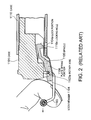
- FIG. 1 is a sectional side view of a conventional transceiver locked in the cage.
- a lock member 1104 provided to a case 1101 has a lock portion 1104a locked in a locking hole 1110a formed on a cage 1110, and is swingable centering on a spindle 1105. If the user turns a lever 1103 on a rotary axis 1103a in an arrow direction, the lock member 1104 coupled to the lever 1103 swings centering on the spindle 1105 so that the lock portion 1104a goes up. The lock portion 1104a comes off the locking hole 1110a of the cage 1110 so as to release the lock between the optical transceiver and the cage.
- FIG. 2 shows a state in which the lock between the optical transceiver and the cage is released. In FIG. 2, if the user pulls the lever 1103 in the arrow direction, the case 1101 of the optical transceiver is detached from the cage 1110.
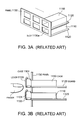
- FIGS. 3A and 3B show an example of mounting multiple optical transceivers in the communication apparatus. Such an example of mounting was developed while almost all the apparatuses including the communication apparatuses were miniaturized and the optical transceivers provided in the communication apparatuses were also miniaturized and rendered high-density in recent years.
- FIG. 3A is a perspective view showing a part of a conventional communication apparatus on which multiple optical transceivers are mountable.
- multiple cages 1110 for mounting the optical transceivers are provided for the sake of allowing the multiple optical transceivers to be provided being mutually adjacent on the left, right, top and bottom in the communication apparatus.
- FIG. 3B shows a state in which the multiple optical transceivers are mounted on the communication apparatus of FIG. 3A.
- the user cannot insert his or her finger between an upper optical transceiver and a lower optical transceiver vertically and adjacently placed. Therefore, the user cannot place his or her finger on the lever 1103 of the optical transceiver and pull it forward. It is not possible, however, to mount the optical transceivers at a high density in the communication apparatus if they are arranged to allow the user to place his or her finger between the upper and lower optical transceivers.
- FIGS. 4A to 5 Other mechanisms for releasing the lock will be described by using FIGS. 4A to 5.
- FIGS. 4A and 4B are a partially sectional view and a perspective view showing a connector-detachable mechanism disclosed in Japanese Utility Model Laid-Open No. 1-162945 respectively.
- FIG. 4A shows a state in which a case 2001 is accommodated in a mounting hardware 2004.
- FIG. 4A shows this state. If the user turns a handle 2002 and pulls it to the front of the case 2001 from the state of FIG. 4A, the case 2001 is pulled out of the mounting hardware 2004, and a first connector 2005 is set apart from a second connector 2006.
- FIG. 4B shows this state.
- FIG. 5 is a perspective view showing the lock mechanism of an electronic device disclosed in Japanese Utility Model Laid-Open No. 2-10153.
- An electronic device 3001 is an in-car electronic device such as a car stereo, which is locked onto a vehicle body not shown.
- FIG. 5 if the user pushes a lock release button 3002, the lock of the electronic device 3001 onto the vehicle body is released, and a handle pressing lever 3023 turns centering on a support 3024 so that a press portion 3023a pushes out a handle 3012 to the front of the electronic device 3001. If the user pulls the pushed-out handle 3012, the electronic device 3001 is pulled out of the vehicle body.
- An object of the present invention is to provide an optical transceiver for improving operability for a user.
- Another object is to provide the optical transceiver to be mounted at a high density and easily pulled out by the user.
- a mechanism for releasing a lock between the optical transceiver and a cage of the present invention includes a lever mounted on the optical transceiver and turning centering on a predetermined axis, an operating member for working with and turning the lever, and a lock release mechanism for releasing the lock by operating the operating member to turn and move the lever from a first position to a second position.
- the operating member should desirably turn the lever by pressing it.
- the operating member should desirably be mounted on the lever. It should desirably be mounted almost vertically on the lever. It is also desirable that the operating member exist below the optical transceiver in a state in which the lever is turned. It is also possible to have the operating member and the lever integrally formed.
- the operating member turns the lever by pulling.
- the operating member should desirably be mounted on the lever.
- first convex portion formed on the concave portion and a second convex portion provided on the slide member so that the move of the lever causes the first and second convex portions to abut and elastic displacement of the plate spring portion due to the abutting releases the lock between the lock portion and the locking hole.
- slide member for being swung centering on the predetermined axis by turning of the lever and sliding along with the move and the lock portion formed on one face of the slide member.
- the lock release mechanism can have the lock between the lock portion and the locking hole released by swinging of the slide member.
- the optical transceiver for releasing the lock with the cage of the present invention includes the lever for turning centering on a predetermined axis, the operating member for working with and turning the lever, and the lock release mechanism for releasing the lock by operating the operating member to turn and move the lever from the first position to the second position.
- the operating member should desirably turn the lever by pressing it.
- the operating member may turn the lever by pulling.
- the lock release mechanism of present invention having the slide member for being swung centering on the predetermined axis by turning of the lever and sliding along with the move can have the lock released by the swinging of the slide member.
- a communication apparatus of the present invention including a board having at least one cage mounted thereon with the optical transceiver locked in the cage of the present invention includes the lever mounted on the optical transceiver and turning centering on the predetermined axis, the operating member for working with and turning the lever, and the lock release mechanism for releasing the lock between the optical transceiver and the cage by operating the operating member to turn and move the lever from the first position to the second position.
- a method of releasing the lock between the optical transceiver and the cage of the present invention includes steps of operating the operating member provided to the optical transceiver, working with operation of the operating member and turning the lever, and releasing the lock by moving the lever to the predetermined position. It is also desirable that the operating step comprises pressing the operating member provided on the optical transceiver. The operating step may also pull the operating member provided on the optical transceiver.
- the step of releasing the lock including the steps of: causing the convex portion formed on the slide member and sliding along with the move of the lever to abut the convex portion formed on the predetermined face of the optical transceiver; and elastically displacing the plate spring portion formed on the predetermined face of the cage should desirably release the lock between the lock portion formed on the predetermined face and the locking hole provided on the plate spring portion. It is desirable that the step of releasing the lock including the step of swinging the slide member mounted on the lever centering on the predetermined axis should desirably release the lock between the lock portion formed on the slide member and the locking hole provided on the cage.
- the user turns a lever 22 and pulls the turned lever 22 and thereby easily and securely releases the lock between a case 11 and a cage 2 so that the operability for the user can be improved.
- the user presses a press portion 51 of an operating member 50 to turn the lever 22, and pulls the turned lever 22 to release the lock between the case 11 and cage 2 so that the user can easily pull the optical transceiver out of the cage 2 even if the optical transceivers are mounted at a high density.
- an optical transceiver 1 refers to the one having at least a case 11, a lever 22, a slide member 21 and an operating member 50.
- FIG. 6A is a perspective view showing a state in which the optical transceiver 1 as a first embodiment of the present invention is inserted in a cage 2.
- FIG. 6B is a perspective view showing a state in which the optical transceiver 1 as the first embodiment of the present invention is pulled out of the cage 2.
- the case 11 of the optical transceiver 1 is configured to be detachable from the cage 2 provided on a board such as a mother board not shown provided to communication apparatus for instance. And when the case 11 of the optical transceiver 1 is completely inserted in the cage 2, it is in a locked state being locked in the cage 2.
- the case 11 of the optical transceiver 1 has a lock portion 17 to be locked on the cage 2.
- the cage 2 has a triangular locking hole 19 for having the lock portion 17 inserted therein.
- the locking hole 19 is provided on a plate spring portion 18 formed to be capable of elastic displacement.
- a lock release mechanism 20 is a mechanism for releasing a lock between the lock portion 17 of the case 11 and the locking hole 19 of the cage 2, and is comprised of the slide member 21, lever 22 and a spindle 23 described later.
- the slide member 21 is movably supported against the case 11, and functions as a lock release member for releasing the lock between the lock portion 17 of the case 11 and the locking hole 19 of the cage 2.
- the lever 22 is provided on a front end face of the case 11, and is formed to be rotatable in directions of arrows c or d. The lever 22 is used to move the slide member 21 in the directions of arrows a or b.
- the operating member 50 is firmly fixed beneath the lever 22. If a user pushes the operating member 50 with his or her finger without placing his or her finger on the lever 22, the lever 22 is turned in the directions of arrows d. Details of structure and functions of the operating member 50 will be described later.
- the case 11 of the optical transceiver 1 has various unshown optical elements which are communication means used for optical communication built therein.
- it includes an optical unit having optical elements such as a Laser Diode (LD) as a light-emitting element, a Photo Diode (PD) as a light-sensitive element or a lens.
- An end connection 11a is formed astride the front end face and a ceiling face of the case 11, and a connector plug of an optical fiber cable not shown is detachably connected to the end connection 11a.
- LD Laser Diode
- PD Photo Diode
- the cage 2 and case 11 are configured, for instance, by bending a metal plate such as stainless used steel (SUS) .
- the case 11 is configured with a mold-formed resin such as Poly Phenylene Sulphide (PPS) for instance.
- PPS Poly Phenylene Sulphide
- FIGS. 7A and 7B are a side view and a bottom view of the optical transceiver 1 shown in FIG. 6A respectively.
- a finger placing portion 22a for the user to place his or her finger is formed in an upper portion of the lever 22.
- the operating member 50 is mounted almost vertically on the lever 22.
- an opening 14 is formed on a bottom face on a back end side of the case 11 in order to expose a joining terminal 13 connected to an electrical connector provided on a board not shown.
- the spindle 23 has its both ends supported by an unshown shaft hole provided on the case 11 while supporting the slide member 21 movably in the directions of the arrows a or b.
- FIGS. 8A and 8B are a bottom view and a side view of the case 11 shown in FIGS. 6A and 6B respectively.
- FIG. 8C is an A to A sectional view of FIG. 8A.
- the triangular and projecting lock portion 17 is formed in a concave portion 16 provided on the bottom face of the case 11.
- the lock portion 17 has an inclined plane 17a formed on an approach end side on which the case 11 approaches the cage 2.
- the inclined plane 17a is formed so that projection height from the bottom face in the concave portion 16 becomes gradually higher as the case 11 gets inserted in the cage 2.
- a guide groove 33 for guiding the slide member 21 in a moving direction is provided on the bottom face of the case 11.
- Depth of the guide groove 33 is almost equal to thickness of the slide member 21 so as not to project the slide member 21 from the bottom face of the case 11.
- the case 11 has a stopper face 38 for regulating the move of the slide member 21 notched and formed at a position adjacent to the guide groove 33.
- the stopper face 38 is formed by making a sharp angle to the side face of the guide groove 33. Therefore, the slide member 21 is prevented from dropping out of the case 11 because, when moved to the case 11 in the arrow b direction of FIG. 6A, a retaining face 37 of each actuating piece 28 described later hits the stopper face 38 to regulate the move of the slide member 21.
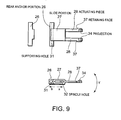
- FIG. 9 is three-sided views showing structure of a slide member 21 from the top, side and front.
- the slide member 21 is comprised of a rear anchor portion 26, a slide portion 27 and actuating pieces 28 which are integrally formed.
- the rear anchor portion 26 has a supporting hole 31 orthogonal to the moving direction of the slide member 21 (the arrow a or b direction of FIG. 4A) and having a predetermined width parallel to the bottom face of the case 11.
- the supporting hole 31 rotatably supports the lever 22.
- the slide portion 27 has a spindle hole 32 like an elongate hole in which the spindle 23 shown in FIG. 7B is movably inserted in the arrow a or b direction.
- the slide member 21 is formed with a resin material such as PPS or an elastic metal for instance.
- Two actuating pieces 28 are formed with a predetermined interval not to collide with the lock portion 17 of the case 11 shown in FIG. 6B, and are configured to be capable of elastic displacement in an arrow Y direction with a supporting point in the vicinity of a boundary between the actuating pieces 28 and the slide portion 27.
- the projection 34 formed at an end of the actuating piece 28 is approximately trapezoidal, and is provided on the face opposed to the bottom face of the case 11 so as to engage the projection 34 with the convex portions 35 formed on the bottom face of the case 11. Consequently, the actuating pieces 28 press the plate spring portion 18 shown in FIGS. 6A and 6B so as to elastically displace the plate spring portion 18 .
- the actuating pieces 28 In a state in which the projection 34 of the actuating piece 28 is not engaged with the convex portions 35, the actuating pieces 28 does not project from inside the concave portion 16 so that the actuating piece 28 does not slidably contact the plate spring portion 18.
- the retaining face 37 On an end side of the actuating piece 28, the retaining face 37 is formed to be approximately orthogonal to the side face of the actuating pieces 28.
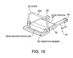
- FIG. 10 is a perspective view showing a state in which the lever 22 and the operating member 50 are combined with the slide member 21.
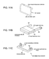
- FIGS. 11A to 11C are exploded perspective views of the lever 22, slide member 21 and operating member 50 respectively.
- FIGS. 10 and 11B a part of one actuating piece 28 is shown in a broken state.
- the lever 22 has the finger placing portion 22a provided in the upper portion and a rotary axis 22b axially supported by the supporting hole 31 of the rear anchor portion 26 described later.
- the user operates the lever 22 by placing his or her finger on the finger placing portion 22a.
- the lever 22 may be formed with the metal such as stainless or the resin such as PPS, and the finger placing portion 22a may be color-coded for each specification of the optical transceiver 1 by a transmission distance as required.
- the rear anchor portion 26 is divided in two along a central axis of the supporting hole 31.
- the members divided in two are mutually joined as if sandwiching the rotary axis 22b of the lever 22 in the supporting hole 31 so that the rear anchor portion 26 can rotatably support the rotary axis 22b.
- a press portion 51 is pushed down by the user in order to turn the lever 22 to the front of the case 11.
- a lever bearing 52 provides torque generated when the user pushes down the press portion 51 to the lever 22.
- a lever grasping portion 53 grasps the rotary axis 22b of the lever 22.
- the operating member 50 is mounted on the lever 22 by setting the lever grasping portion 53 in the rotary axis 22b of the lever 22 supported by the rear anchor portion 26 from the bottom of FIG. 11A.
- the press portion 51 of the operating member 50 is positioned anterior to the front end face of the case 11 and lower than an area anterior to the end connection 11a formed on the case 11 as shown in FIGS. 6A and 6B.
- the operating member 50 is formed by bending a metal plate formed in a predetermined form. For instance, it may be formed by bending wiry metal into the predetermined form.
- FIGS. 12 to 17B operation for releasing the lock between the case 11 and the cage 2.
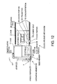
- FIG. 12 is a side view of the optical transceiver 1 showing a state in which the case 11 and cage 2 of the optical transceiver 1 are locked.
- the case 11 of the optical transceiver 1 is inserted in the cage 2, the lock portion 17 and locking hole 19 are locked, and the lever 22 is placed at a position abutting the front side of the case 11.
- the press portion 51 of the operating member 50 is placed at a position projecting on the front side of the case 11.
- the projection 34 of each actuating piece 28 of the slide member 21 is separated from the convex portion 35.
- Each actuating piece 28 keeps a position approximately parallel with the bottom face of the concave portion 16 so as to secure a gap between itself and the plate spring portion 18.
- the user needs to turn the lever 22 in the arrow d direction to bring it down on the front side of the case 11. For that reason, the user turns the lever 22 in the arrow d direction by placing his or her finger on the finger placing portion 22a of the lever 22 positioned in the upper portion of the optical transceiver 1. In this case, it is also possible for the user to turn the lever 22 in the arrow d direction by pushing the press portion 51 in an arrow X direction.
- the direction of pushing is not limited to the X direction but may be another direction, such as a Y direction for instance.
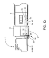
- FIG. 13 is a side view of the optical transceiver 1 showing a state in which the lever 22 is turned in the direction of the arrow d of FIG. 12 and projecting to a front side of the case 11.
- the lever 22 is turned in the arrow d direction, the user can easily pull out the case 11 by using the lever 22.
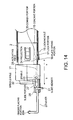
- FIG. 14 is a side view of the optical transceiver 1 showing a state in which the lever 22 is pulled in the direction of the arrow b.
- the slide member 21 moves likewise in the arrow b direction.
- the slide member 21 moves in the arrow b direction along the spindle 23 inserted into the spindle hole 32 of the slide portion 27.
- the projection 34 of the actuating piece 28 abuts the convex portion 35.
- the actuating piece 28 is elastically displaced with its rear anchor as the supporting point so as to sag and project an end portion thereof from inside the concave portion 16 to below the case 11.
- the end portion of the actuating piece 28 presses the plate spring portion 18, and elastically displaces the plate spring portion 18 in the direction for releasing the lock between the lock portion 17 and the locking hole 19.
- the slide member 21 has a configuration wherein, when the slide portion 27 moves to the position to have the spindle 23 hit by the other end face of the spindle hole 32, the projection 34 of the actuating piece 28 stops near a top over the top of the convex portion 35 so as to keep an abutting state of the projection 34 and the convex portion 35. For that reason, when the slide portion 27 is placed at the position to have the spindle 23 hit by the other end face of the spindle hole 32, the plate spring portion 18 is kept in the state of having the lock between the lock portion 17 and the locking hole 19 released by the actuating piece 28. Therefore, it is possible to pull the case 11 out of the cage 2 in this state.
- FIG. 15 is a side view of the optical transceiver 1 showing a state in which the lever 22 is further pulled in the direction of the arrow b and the case 11 is pulled out of the cage 2.
- the slide portion 27 can move in a range in which the spindle hole 32 is movable along the spindle 23 so that a moving range of the slide member 21 in the arrow a or b directions is securely regulated and also the positioning is securely performed as to relative positions in the moving direction of the projection 34 of the actuating piece 28 and convex portion 35.
- FIGS. 16A to 17B are diagrams for describing the operation for pulling the optical transceiver 1 of the present invention out of the cage 2 on the communication apparatus having multiple optical transceivers 1 mounted at a high density thereon.
- the user cannot place his or her finger on the finger placing portion 22a in the upper portion of the lever 22 because the optical transceivers 1 are placed at a high density vertically.
- the user can turn the lever 22 in the arrow d direction by pushing the press portion 51 in an arrow X direction.
- the torque generated on the rotary axis 22b of the lever 22 is given to the lever 22 by the lever bearing 52 supporting a backside of the lever 22 so that the lever 22 turns in the arrow d direction shown in FIGS. 12 and 13.
- the direction of pushing is not limited to the X direction but may be another direction, such as the Y direction for instance.
- FIG. 17A shows a state in which the lever 22 turns and projecting to the front side of the case 11. Therefore, as shown in FIG. 17B, the user can pull the optical transceiver 1 out of the cage 2 by pulling the lever 22 projecting to the front side of the case 11 in the arrow b direction.
- the user can turn the lever 22 and pull out the turned lever 22 and thereby easily and securely release the lock between the case 11 and the cage 2. Therefore, the user can easily pull the case 11 out of the cage 2 so that the operability for the user can be improved.
- optical transceivers 1 are mounted at such a high density that the user cannot turn the lever 22, it is possible, according to the optical transceiver 1 of the present invention, for the user to turn the lever 22 easily by pressing the press portion 51 of the operating member 50. For that reason, it is possible to improve the operability for the user while miniaturizing and rendering high-density the communication apparatuses having the multiple optical transceivers 1 mounted thereon.
- the plate spring portion 18 of the cage 2 is elastically displaced gradually and pushed down by the inclined plane 17a of the lock portion 17 once the case 11 is inserted in the cage 2 in the arrow a direction shown in FIG. 6A. If the case 11 is further inserted in the cage 2, the lock portion 17 is locked in the locking hole 19 and the case 11 is completely locked in the cage 2.
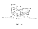
- FIG. 18 is a perspective view showing a state in which a slide member 25 and a lever 24 are combined according to a second embodiment of the present invention.
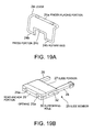
- FIGS. 19A and 19B are exploded perspective views of the lever 24 and slide member 25 respectively. As with FIGS. 11 and 12, a part of one actuating piece 28 is shown in a broken state.
- the optical transceiver 3 of this embodiment does not comprise the operating member 50 of the first embodiment, and has a press portion 24c formed as a part of the lever 24.
- the same components as those of the first embodiment are given the same reference characters.
- the slide portion 27 and actuating piece 28 of this embodiment have the same configurations as those in the first embodiment, and so a description thereof will be omitted in order to avoid redundancy.
- the lever 24 comprises the press portion 24c in addition to a finger placing portion 24a provided in the upper portion and a rotary axis 24b axially supported by a supporting hole 30 of a rear anchor portion 29.
- the press portion 24c is pushed down by the user in order to turn the lever 24 to the front of the case 11.
- the press portion 24c is positioned anterior to the front end face of the case 11 and lower than the area anterior to the end connection 11a of the case 11.
- the lever 24 may be formed with the metal such as stainless or the resin such as PPS, and the finger placing portion 24a may be color-coded for each specification of the optical transceiver 3 by the transmission distance, for instance, as required.
- the rear anchor portion 29 is divided in two along a central axis of the supporting hole 30.
- the members of the rear anchor portion 29 divided in two are mutually joined as if sandwiching the rotary axis 24b of the lever 24 in the supporting hole 30 so that the rear anchor portion 29 can rotatably support the rotary axis 24b.
- Two openings 29a are formed on the front side of the rear anchor portion 29, and the press portion 24c of the lever 24 is projected to the front side of the rear anchor portion 29 through these openings 29a.
- FIGS. 20 to 25B a description will be given by referring to FIGS. 20 to 25B as to the operation for releasing the lock between the case 11 and the cage 2 according to the present embodiment.
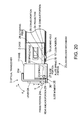
- FIG. 20 is a side view of an optical transceiver 3 showing the state in which the case 11 and cage 2 of the optical transceiver 3 are locked according to the second embodiment of the present invention.
- the press portion 24c is placed at a position projecting to the front side of the case 11.
- the user needs to turn the lever 24 in the arrow d direction to bring it down on the front side of the case 11. For that reason, the user turns the lever 24 in the arrow d direction by placing his or her finger on the finger placing portion 24a of the lever 24 positioned in the upper portion of the optical transceiver 3.
- the user can turn the lever 24 in the arrow d direction by pushing the press portion 24c in the arrow X direction.
- the direction of pushing is not limited to the X direction but may be another direction, such as the Y direction for instance.
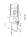
- FIG. 21 is a side view of the optical transceiver 3 showing a state in which the lever 24 is turned in the direction of the arrow d of FIG. 20 and projecting to the front side of the case 11.
- FIG. 22 is a side view of the optical transceiver 3 showing a state in which the lever 24 is pulled in the direction of the arrow b.
- FIG. 23 is a side view of the optical transceiver 3 showing a state in which the lever 24 is further pulled in the direction of the arrow b and the case 11 is pulled out of the cage 2.
- the description of FIGS. 22 and 23 is the same as that of FIGS. 14 and 15, which will be omitted in order to avoid redundancy.
- the press portion 24c is positioned in a lower front part of the optical transceiver 3 rather than in a vertical direction to the case 11 of the optical transceiver 3.
- FIGS. 24A to 25B are diagrams for describing the operation for pulling the optical transceiver 3 of the present invention out of the cage 2 on the communication apparatus having the multiple optical transceivers 3 mounted at a high density thereon.
- the user can turn the lever 24 in the arrow d direction by pushing the press portion 24c in the arrow X direction.
- the torque generated on the rotary axis 24b of the lever 24 is given to the lever 24 so that the lever 24 turns in the arrow d direction shown in FIGS. 20 and 21.
- the direction of pushing is not limited to the X direction but may be another direction, such as the Y direction for instance.
- FIGS. 24A, 25A and 25B The description of FIGS. 24A, 25A and 25B is the same as that of FIGS. 16A, 17A and 17B, which will be omitted in order to avoid redundancy. ,
- the optical transceiver 3 of this embodiment for the user to turn the lever 24 easily by pressing the press portion 24c. For that reason, it is possible to improve the operability for the user on the communication apparatuses having the multiple optical transceivers 3 mounted thereon which is miniaturized and rendered high-density.
- the press portion 24c is integrally formed with the lever 24 according to this embodiment, it is not necessary to separately provide the operating member 50 shown in the first embodiment. Consequently, it is possible to reduce manufacturing costs and simplify a manufacturing process.
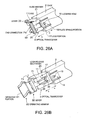
- FIG. 26A is a perspective view showing a state in which an optical transceiver 4 as the third embodiment of the present invention is inserted in the cage 2.
- FIG. 26B is a perspective view showing a state in which the optical transceiver 4 of FIG. 26A is pulled out of the cage 2.
- the optical transceiver 4 of this embodiment has an operating member 60 different from the operating member 50 of the first embodiment in the upper portion of the lever 22.
- the same components as those of the first embodiment are given the same reference characters.
- the configuration other than the operating member 60 of this embodiment is the same as that in the first embodiment, and so a description thereof will be omitted in order to avoid redundancy.
- the operating member 60 is mounted above the lever 22. If the user pulls the operating member 60 forward without placing his or her finger on the lever 22, the lever 22 is turned in the directions of arrows d.
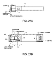
- FIGS. 27A and 27B are a side view and a bottom view of the optical transceiver 4 shown in FIG. 26A respectively.
- the operating member 60 is approximately in the same form as the lever 22. However, the end thereof including an operating portion 61 to be held by the user with his or her fingers is positioned lower than the front area of the end connection 11a, that is, at the lower front of the optical transceiver 4 so that the base of the lever 22 and the operating member 60 constitute a sharp angle.
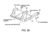
- FIG. 28 is a perspective view showing a state in which the lever 22 and the operating member 60 are combined with the slide member 21.
- FIGS. 29A to 29C are exploded perspective views of the lever 22, slide member 21 and operatingmember 60 respectively.
- FIGS. 28 and 29B a part of one actuating piece 28 is shown in a broken state.
- the operating member 60 has the operating portion 61 and a supporting hole 62.
- the operating portion 61 is pulled out by the user in order to turn the lever 22 to the front.
- the supporting hole 62 supports the operating member 60 rotatably in the proximity of both ends of the finger placing portion 22a of the lever 22.
- the operating member 60 is mounted on the lever 22 as follows.
- the supporting hole 62 of the operating member 60 is bored on both ends of the upper portion of the lever 22 before the finger placing portion 22a is mounted on the lever 22. Subsequently, the finger placing portion 22a is inserted in both ends of the upper portion of the lever 22, and the operating member 60 is thereby mounted on the lever 22.
- the operating member 60 is formed by bending a metal plate formed in a predetermined form. For instance, it may be formed by bending wiry metal into the predetermined form.
- FIG. 30 is a side view of the optical transceiver 4 showing a state in which the case 11 and cage 2 of the optical transceiver 4 of the third embodiment are locked.
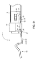
- FIG. 31 is a side view of the optical transceiver 4 showing a state in which the lever 22 is turned in the direction of the arrow d of FIG. 30 and projecting to the front side of the case 11.
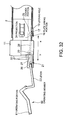
- FIG. 32 is a side view of the optical transceiver 4 showing a state in which the operating portion 61 is pulled in the direction of the arrow b.
- FIG. 33 is a side view of the optical transceiver 4 showing a state in which the operating portion 61 is further pulled in the direction of the arrow b and the case 11 is pulled out of the cage 2.
- the description of FIGS. 32 and 33 is the same as that of FIGS. 14 and 15, which will be omitted in order to avoid redundancy.
- the operating member 60 is positioned at the front of the case 11 of the optical transceiver 4 rather than in a vertical direction thereto. In this case, the operating portion 61 is positioned approximately in the same direction as the direction in which the lever 22 is pulled.
- FIGS. 34A to 35B are diagrams for describing the operation for pulling the optical transceiver 4 of the present invention out of the cage 2 on the communication apparatus having multiple optical transceivers 4 mounted at a high density thereon.
- the user can turn the lever 22 in the arrow d direction by pulling the operating member 60 in the X direction.
- the lever 22 coupled to the operating member 60 is simultaneously pulled and so the lever 22 turns in the arrow d direction shown in FIGS.30 and 31.
- the direction of pulling is not limited to the X direction but may be another direction, such as a Y direction for instance.
- FIG. 35A shows a state in which the operating member 60 is pulled and the lever 22 turns so that both are projecting to the front side of the case 11. Therefore, as shown in FIG. 35B, the user can pull the optical transceiver 4 out of the cage 2 by pulling the operating member 60 projecting to the front side of the case 11 in the arrow b direction.
- the optical transceiver 4 of this embodiment it is possible for the user to turn the lever 22 easily by pulling the operating member 60. For that reason, it is possible to improve operability for the user on the communication apparatus having the multiple optical transceivers 4 mounted thereon which is miniaturi zed and rendered high-density.
- the user turns the lever 22 by pulling the operating member 60 and releases the lock between the optical transceiver 4 and the cage 2 by further pulling the operating member 60 without moving his or her finger. Therefore, it is no longer necessary for the user to switch as in the case of pulling the optical transceiver 4 out of the cage 2 according to the first and second embodiments. Thus, it can further improve the operability for the user.
- FIG. 36A is a perspective view showing a case 101, a lever 103 to be mounted on the case 101 and a slide member 104 of an optical transceiver 100 as a fourth embodiment of the present invention.
- FIG. 36B is an enlarged view of an A portion of the case 101 shown in FIG. 36A.
- the optical transceiver 100 of this embodiment is comprised of the case 101, the lever 103 to be mounted in the vicinity of the front of the case 101 and the slide member 104.
- the lever 103 has a rotary axis 103a, an operating portion 103b provided in the upper portion of the lever 103 and a press portion 103c. If the user places his or her finger on the operating portion 103b and pushes it down, the lever 103 is turned forward with the rotary axis 103a as the axis.
- the press portion 103c is roughly horseshoe-shaped. The ends of the press portion 103c are connected in proximity to both ends of the rotary axis 103a of the lever 103.
- the press portion 103c is positioned anterior to the front end face of the case 101 and lower than the area anterior to the end connection 101a of the case 101.
- the case 101 has a notch groove 102 and a groove 106 provided on the front thereof.
- the notch groove 102 has the rotary axis 103a of the lever 103 set therein, and the groove 106 has a spindle 105 of the slide member 104 set therein.
- the case 101 also has lever stoppers 101b formed on both anterior sides, where bilateral portions of the lever 103 are locked on the lever stoppers 101b so that the lever 103 is fixed at a predetermined position of the case 101.
- the lever 103 and slide member 104 are mounted on the case 101 as follows. First, the rotary axis 103a of the lever 103 is set in the notch groove 102 of the case 101. Next, the spindle 105 of the slide member 104 is set in the groove 106 of the case 101 as if sandwiching the rotary axis 103a of the lever 103 between the case 101 and the slide member 104. Thus, the lever 103 turns centering on the rotary axis 103a supported in the notch groove 102, and the slide member 104 can swing centering on the spindle 105 supported in the groove 106.
- the case 101 of the optical transceiver 100 has various unshown optical elements which are the communication means for performing the optical communication built therein.
- it includes the optical unit having the optical elements such as the LD as the light-emitting element and the PD or lens as the light-sensitive element.
- the end connection 101a is formed astride the front end face and the ceiling face of the case 101, and the connector plug of the optical fiber cable not shown is detachably connected to the end connection 101a.
- the operating portion 103b is comprised of a first part and a second part, and has a gap between them. This is intended, on connecting the connector plug of the optical fiber cable to the end connection 101a, to avoid it from blocking movement of the lever 103.
- FIG. 37A is a perspective view showing an upside of the slide member 104 shown in FIG. 36A.
- the slide member 104 has a front portion 104a and a back portion 104c.
- the front portion 104a has a cam face 104f of which height becomes higher from the spindle 105 to the front end of the front portion 104a formed on a top face thereof.
- the front portion 104a also has shoulder portions 104b provided on both sides of the front end thereof. If the lever 103 shown in FIG.
- a spring portion 104e as energizing means extends almost in parallel with the top face of the back portion 104c.
- One end of the spring portion 104e is fixed approximately at the center of the top face of the slide member 104.
- the slide member 104 is integrally mold-formed with the spindle 105 for instance.
- the resin such as PPS is used as a material thereof for instance.
- the portions of the slide member 104 other than the spring portion 104e are integrally formed with the resin such as PPS, to mount the spring portion 104e on that molding.
- the material of the spring portion 104e it is possible, as to the material of the spring portion 104e, to use a material different from that of the portions other than the spring portion 104e. For instance, only the spring portion 104e may be configured by metal.
- FIG. 37B is a perspective view showing a downside of the slide member 104 shown in FIG. 36A.
- a projection-like lock portion 104d is provided on the bottom face of the backportion 104c of the slidemember 104.
- the lockportion 104d and a locking hole 110a described later are locked so that the case 101 of the optical transceiver 100 is locked in the cage 110.
- FIG. 38 is a perspective view showing a state in which the case 101 of the optical transceiver 100 shown in FIGS. 36A and 36B is inserted in the cage 110.
- the locking hole 110a is provided on the bottom face of the cage 110. The locking hole 110a is placed at the position to be locked by the lock portion 104d of the slide member 104 when the case 101 is inserted in the cage 110.
- the cage 110 and case 101 are configured, for instance, by bending the metal plate such as stainless used steel.
- the case 101 is configured with a mold-formed resin such as PPS for instance as with the slide member 104.
- the lever 103 is formed with the metal such as stainless or the resin material such as PPS for instance.
- FIGS. 39 and 40 the portion hidden in the case 101 of the slide member 104 is shown in broken line.
- FIG. 39 is a side view of the optical transceiver 100 showing a state in which the case 101 of the optical transceiver 100 is locked in the cage 110 according to a fourth embodiment.
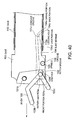
- FIG. 40 is a side view of the optical transceiver 100 showing a state in which the lock between the lock between the case 101 and the cage 110 of the optical transceiver 100 of the fourth embodiment is released.
- the slide member 104 keeps a parallel posture to the case 101, and the lock portion 104d of the slide member 104 is locked in the locking hole 110a of the cage 110.
- the rotary axis 103a of the lever 103 is positioned on the back end side of the notch groove 102.
- the rotary axis 103a is at the lowest position of the cam face 104f formed on the front portion 104a of the slide member 104. If the lever 103 is turned and the lock of the lever 103 by the lever stoppers 101b is released, the lever 103 turns centering on the rotary axis 103a positioned on the back end side of the notch groove 102 so as to project to the front of the case 101 as shown in dashed line.
- the lever 103 is turned to the front of the case 101 by the user placing his or her finger on the operating portion 103b. However, it may also be turned by the user pushing down the press portion 103c.
- lever 103 If the lever 103 is pulled out of the lever stoppers 101b, it may be automatically turned to a position to be easily held.
- the rotary axis 103a of the lever 103 moves from the lowest position of the cam face 104f to the position abutting the front end of the notch groove 102.
- the rotary axis 103a pushes down the cam face 104f formed on the front portion 104a of the slide member 104. If the cam face 104f is pushed down, the slide member 104 swings centering on the spindle 105 in the groove 106 so that the spring portion 104e and the back portion 104c are heaved upward.
- the spring portion 104e heaved upward abuts a concave groove 101c formed on the bottom face of the case 101 and sags, and the lock portion 104d on the bottom face of the back portion 104c comes off the locking hole 110a of the cage 110.
- the lock between the case 101 and the cage 110 is released.
- the slide member 104 is held in an inclined state and so the lock between the case 101 and the cage 110 is continuously released. Therefore, the user can pull the lever 103 to the front of the case 101 from the state in which the lever 103 is turned so as to pull the case 101 of the optical transceiver 100 out of the cage 110.
- the back portion 104c of the slide member 104 is pushed down by restoring force of the spring portion 104e which was sagging till then, and the slide member 104 tries to swing in the opposite direction to the direction for releasing the lock centering on the spindle 105.
- the rotary axis 103a of the lever 103 is pushed backward in the notch groove 102 along the cam face 104f so as to abut the back end in the notch groove 102 after a while. If the rotary axis 103a of the lever 103 abuts the back end in the notch groove 102, the slide member 104 returns to the original parallel posture to the case 101 shown in FIG. 39.
- the operating portion 103b of the lever 103 abuts the connector plug so that the lever 103 is not turned at least up to the position shown in FIG. 40.
- the lever 103 is turned only up to the position to abut the connector plug so that the lock portion 104d does not come off the locking hole 110a. For that reason, it is possible to prevent the case 101 of the optical transceiver 100 from being pulled out of the cage 110 by mistake while the optical transceiver 100 is performing communication. Thus, it is possible to prevent an interruption in the communication and a failure of the optical transceiver 100.
Landscapes
- Physics & Mathematics (AREA)
- General Physics & Mathematics (AREA)
- Optics & Photonics (AREA)
- Optical Couplings Of Light Guides (AREA)
Applications Claiming Priority (4)
| Application Number | Priority Date | Filing Date | Title |
|---|---|---|---|
| JP2004118008A JP4306522B2 (ja) | 2004-04-13 | 2004-04-13 | 光モジュールの係止解除機構、光モジュール、および光モジュールとケージとの係止状態を解除する方法 |
| JP2004118008 | 2004-04-13 | ||
| JP2004154622A JP2005338247A (ja) | 2004-05-25 | 2004-05-25 | 光モジュールの係止解除機構、光モジュール、および光モジュールとケージとの係止状態を解除する方法 |
| JP2004154622 | 2004-05-25 |
Publications (1)
| Publication Number | Publication Date |
|---|---|
| EP1593993A1 true EP1593993A1 (de) | 2005-11-09 |
Family
ID=34935034
Family Applications (1)
| Application Number | Title | Priority Date | Filing Date |
|---|---|---|---|
| EP05007970A Withdrawn EP1593993A1 (de) | 2004-04-13 | 2005-04-12 | Mechanismus zur Lösung der Entrastung zwischen optischem Sende- und Empfangsmodul und der Aufnahme des Moduls |
Country Status (2)
| Country | Link |
|---|---|
| US (1) | US7317862B2 (de) |
| EP (1) | EP1593993A1 (de) |
Cited By (4)
| Publication number | Priority date | Publication date | Assignee | Title |
|---|---|---|---|---|
| GB2481703A (en) * | 2010-06-30 | 2012-01-04 | Avago Tech Fiber Ip Sg Pte Ltd | Optoelectronic module and method for removal |
| WO2015016332A1 (en) * | 2013-08-01 | 2015-02-05 | Sumitomo Electric Industries, Ltd. | Optical transceiver having bail working independently of linear motion of slider |
| CN104516067A (zh) * | 2014-12-04 | 2015-04-15 | 武汉电信器件有限公司 | 一种光电模块上锁与解锁机构 |
| WO2015142950A1 (en) * | 2014-03-17 | 2015-09-24 | Finisar Corporation | Latch mechanisms for modules |
Families Citing this family (32)
| Publication number | Priority date | Publication date | Assignee | Title |
|---|---|---|---|---|
| CN201263155Y (zh) * | 2008-08-20 | 2009-06-24 | 鸿富锦精密工业(深圳)有限公司 | 小型可插拔模组及其释出机构 |
| US8064207B2 (en) * | 2008-10-14 | 2011-11-22 | Hon Hai Precision Ind. Co., Ltd. | Electronic module with ejector mechanism |
| JP2010101944A (ja) * | 2008-10-21 | 2010-05-06 | Nec Corp | 光モジュールのロック機構 |
| CN101762850B (zh) * | 2008-12-26 | 2012-01-25 | 华为技术有限公司 | 一种光模块 |
| JP5440304B2 (ja) * | 2010-03-19 | 2014-03-12 | 富士通株式会社 | 光半導体装置及びその製造方法 |
| CN201829731U (zh) * | 2010-09-15 | 2011-05-11 | 富士康(昆山)电脑接插件有限公司 | 电连接器组件 |
| US8393802B2 (en) * | 2010-09-30 | 2013-03-12 | Apple Inc. | Cleanable and self-cleaning fiber optic connector |
| JP2012194451A (ja) * | 2011-03-17 | 2012-10-11 | Nec Corp | 光モジュールのロック機構 |
| US8506172B2 (en) * | 2011-03-29 | 2013-08-13 | Avago Technologies General Ip (Singapore) Pte. Ltd. | Optical transceiver module equipped with an elongated delatching pull tab, and a method |
| US9164247B2 (en) * | 2011-07-28 | 2015-10-20 | Source Photonics, Inc. | Apparatuses for reducing the sensitivity of an optical signal to polarization and methods of making and using the same |
| CN103718392B (zh) * | 2011-09-16 | 2016-11-16 | 浩亭电子有限公司 | 用于电连接件的锁定装置 |
| US9028155B2 (en) * | 2012-05-31 | 2015-05-12 | Source Photonics, Inc. | Latchable module housings and methods of making and using the same |
| US8571375B1 (en) * | 2012-06-25 | 2013-10-29 | George Kyi | Release mechanism and transceiver module using the same |
| CN203054267U (zh) * | 2012-12-14 | 2013-07-10 | 泰科电子(上海)有限公司 | 防尘装置和连接器组件 |
| CN104749716A (zh) * | 2013-12-31 | 2015-07-01 | 台达电子工业股份有限公司 | 光纤连接器 |
| TWM522365U (zh) * | 2014-12-22 | 2016-05-21 | 智邦科技股份有限公司 | 結合組件 |
| TWI547029B (zh) * | 2015-03-26 | 2016-08-21 | 啟碁科技股份有限公司 | 網路設備及其連接器 |
| CN204719275U (zh) * | 2015-06-09 | 2015-10-21 | 昂纳信息技术(深圳)有限公司 | 一种qsfp+模块直拉式解锁结构 |
| EP3271763B1 (de) * | 2015-07-30 | 2021-09-01 | Hewlett Packard Enterprise Development LP | Sende- und empfangsmodul |
| TWI641883B (zh) | 2017-03-03 | 2018-11-21 | 英屬維京群島商祥茂光電科技股份有限公司 | 光收發器 |
| TWI616696B (zh) * | 2017-03-03 | 2018-03-01 | 英屬維京群島商祥茂光電科技股份有限公司 | 光收發器 |
| CN109116478B (zh) * | 2017-06-26 | 2020-11-24 | 台达电子工业股份有限公司 | 可插拔收发模块 |
| US10288824B2 (en) * | 2017-10-02 | 2019-05-14 | Prime World International Holdings Ltd. | Optical transceiver |
| CN109991704A (zh) * | 2018-01-02 | 2019-07-09 | 台达电子工业股份有限公司 | 光收发模块 |
| CN111830640A (zh) * | 2019-04-19 | 2020-10-27 | 台达电子工业股份有限公司 | 光收发模块 |
| JP7347146B2 (ja) * | 2019-11-15 | 2023-09-20 | 富士通オプティカルコンポーネンツ株式会社 | 光モジュール |
| EP4071531B1 (de) * | 2019-12-31 | 2025-04-23 | Huawei Technologies Co., Ltd. | Entriegelungsvorrichtung für optische module, optisches modul und optische kommunikationsvorrichtung |
| CN113496647B (zh) * | 2020-04-07 | 2023-05-12 | 明基智能科技(上海)有限公司 | 具有遮挡板的装置及显示装置 |
| US11372177B2 (en) * | 2020-04-21 | 2022-06-28 | Ii-Vi Delaware, Inc. | Pluggable transceiver retainer |
| US11340411B2 (en) | 2020-04-21 | 2022-05-24 | Ii-Vi Delaware, Inc. | Pluggable transceiver retainer |
| CN111562655B (zh) * | 2020-06-12 | 2021-11-12 | 索尔思光电(成都)有限公司 | 解锁件、解锁机构及其装配方法、光模块 |
| US12158613B2 (en) * | 2022-02-02 | 2024-12-03 | Sanwa Technologies, Inc. | Optical connector switches, systems, and methods |
Citations (7)
| Publication number | Priority date | Publication date | Assignee | Title |
|---|---|---|---|---|
| US6430053B1 (en) * | 2001-12-13 | 2002-08-06 | Stratos Lightwave | Pluggable transceiver module having rotatable release and removal lever with living hinge |
| US6533603B1 (en) * | 2001-10-04 | 2003-03-18 | Finisar Corporation | Electronic module having an integrated latching mechanism |
| US20030156801A1 (en) * | 2002-02-20 | 2003-08-21 | Jenq-Yih Hwang | Optoelectrical transceiver module with de-latching mechanism |
| US20030194190A1 (en) * | 2002-04-12 | 2003-10-16 | Huang Nan Tsung | Optoelectrical transceiver module with releasing mechanism |
| US20030198026A1 (en) * | 2002-04-22 | 2003-10-23 | Optical Communication Products, Inc. | Pluggable optical transceiver with pivoting actuator lever |
| US20030228799A1 (en) * | 2002-04-16 | 2003-12-11 | Machado Russell L. | Shielded connector assembly and method of manufacturing |
| US20040062493A1 (en) * | 2002-09-30 | 2004-04-01 | Hitachi Cable, Ltd. | Package having lock mechanism |
Family Cites Families (14)
| Publication number | Priority date | Publication date | Assignee | Title |
|---|---|---|---|---|
| US194190A (en) * | 1877-08-14 | Improvement in cultivators | ||
| US198026A (en) * | 1877-12-11 | Improvement in fire-escapes | ||
| US156801A (en) * | 1874-11-10 | Improvement in hamdles for tea amd coffee pots | ||
| US228799A (en) * | 1880-06-15 | Aldrich | ||
| US62493A (en) * | 1867-02-26 | Gael lehnert | ||
| JPH07104802B2 (ja) | 1987-12-18 | 1995-11-13 | 富士通株式会社 | 情報処理装置 |
| JP2560787B2 (ja) | 1988-06-28 | 1996-12-04 | 三菱電機株式会社 | 超音波探傷方式 |
| US6494623B1 (en) * | 2001-08-09 | 2002-12-17 | Infineon Technologies Ag | Release mechanism for pluggable fiber optic transceiver |
| US6789958B2 (en) * | 2001-08-31 | 2004-09-14 | Infineon Technologies Ag | Release mechanism for pluggable fiber optic transceiver |
| US6439918B1 (en) * | 2001-10-04 | 2002-08-27 | Finisar Corporation | Electronic module having an integrated latching mechanism |
| US6746158B2 (en) * | 2002-01-31 | 2004-06-08 | Agilent Technologies, Inc. | Pull detach mechanism for fiber optic transceiver module |
| US6935882B2 (en) * | 2002-06-21 | 2005-08-30 | Jds Uniphase Corporation | Pluggable optical transceiver latch |
| JP4338960B2 (ja) * | 2002-11-19 | 2009-10-07 | 日本電気株式会社 | 光モジュールのロック機構 |
| JP4567958B2 (ja) * | 2003-01-21 | 2010-10-27 | 日立電線株式会社 | ロック機構付きパッケージ |
-
2005
- 2005-04-11 US US11/103,120 patent/US7317862B2/en not_active Expired - Fee Related
- 2005-04-12 EP EP05007970A patent/EP1593993A1/de not_active Withdrawn
Patent Citations (7)
| Publication number | Priority date | Publication date | Assignee | Title |
|---|---|---|---|---|
| US6533603B1 (en) * | 2001-10-04 | 2003-03-18 | Finisar Corporation | Electronic module having an integrated latching mechanism |
| US6430053B1 (en) * | 2001-12-13 | 2002-08-06 | Stratos Lightwave | Pluggable transceiver module having rotatable release and removal lever with living hinge |
| US20030156801A1 (en) * | 2002-02-20 | 2003-08-21 | Jenq-Yih Hwang | Optoelectrical transceiver module with de-latching mechanism |
| US20030194190A1 (en) * | 2002-04-12 | 2003-10-16 | Huang Nan Tsung | Optoelectrical transceiver module with releasing mechanism |
| US20030228799A1 (en) * | 2002-04-16 | 2003-12-11 | Machado Russell L. | Shielded connector assembly and method of manufacturing |
| US20030198026A1 (en) * | 2002-04-22 | 2003-10-23 | Optical Communication Products, Inc. | Pluggable optical transceiver with pivoting actuator lever |
| US20040062493A1 (en) * | 2002-09-30 | 2004-04-01 | Hitachi Cable, Ltd. | Package having lock mechanism |
Cited By (8)
| Publication number | Priority date | Publication date | Assignee | Title |
|---|---|---|---|---|
| GB2481703A (en) * | 2010-06-30 | 2012-01-04 | Avago Tech Fiber Ip Sg Pte Ltd | Optoelectronic module and method for removal |
| US8517616B2 (en) | 2010-06-30 | 2013-08-27 | Avago Technologies General Ip (Singapore) Pte. Ltd. | Optoelectronic module having an adapter for use in extracting the module from a cage |
| GB2481703B (en) * | 2010-06-30 | 2014-06-25 | Avago Technologies General Ip | Optoelectronic module, communications device and method of extracting an optoelectronic module from a cage |
| WO2015016332A1 (en) * | 2013-08-01 | 2015-02-05 | Sumitomo Electric Industries, Ltd. | Optical transceiver having bail working independently of linear motion of slider |
| US9523828B2 (en) | 2013-08-01 | 2016-12-20 | Sumitomo Electric Industries, Ltd. | Optical transceiver having bail working independently of linear motion of slider |
| WO2015142950A1 (en) * | 2014-03-17 | 2015-09-24 | Finisar Corporation | Latch mechanisms for modules |
| US9348101B2 (en) | 2014-03-17 | 2016-05-24 | Finisar Corporation | Latch mechanisms for modules |
| CN104516067A (zh) * | 2014-12-04 | 2015-04-15 | 武汉电信器件有限公司 | 一种光电模块上锁与解锁机构 |
Also Published As
| Publication number | Publication date |
|---|---|
| US7317862B2 (en) | 2008-01-08 |
| US20050226587A1 (en) | 2005-10-13 |
Similar Documents
| Publication | Publication Date | Title |
|---|---|---|
| US7317862B2 (en) | Mechanism for releasing lock between optical transceiver and cage, optical transceiver, communication apparatus and method of releasing lock between optical transceiver and cage | |
| JP4458239B2 (ja) | ロック解除機構、光モジュール、および係止状態を解除する方法 | |
| US7513693B2 (en) | Fiber optic connector release mechanism | |
| US6887092B2 (en) | Optical module locking mechanism for locking optical module case and cage for housing case to each other | |
| JP4783096B2 (ja) | 可撓性導体用コネクタ | |
| US6530784B1 (en) | Display connection structure of electronic appliance | |
| US9379487B2 (en) | Card connector | |
| US20090274468A1 (en) | Transceiver module with releasing mechanism | |
| JPH11242137A (ja) | 挿入型の光学用ラック/プラグ接続部のプラグ構造 | |
| EP0895178B1 (de) | Kartenverbinder | |
| US20040110406A1 (en) | Connector module with lever actuated release mechanism | |
| JP5761333B2 (ja) | 光モジュール | |
| JP4306522B2 (ja) | 光モジュールの係止解除機構、光モジュール、および光モジュールとケージとの係止状態を解除する方法 | |
| US7347711B1 (en) | Fiber optic module release mechanism | |
| JP2012195155A (ja) | レバー治具及びコネクタ装置 | |
| JP4816519B2 (ja) | 光トランシーバ | |
| CN118355571A (zh) | 用于附接到线缆的附接装置 | |
| JP2008218335A (ja) | カード用コネクタ装置 | |
| JP2010101944A (ja) | 光モジュールのロック機構 | |
| JP2016048657A (ja) | コネクタの抜去機構と、光モジュール | |
| JP4289369B2 (ja) | ロック機構 | |
| JP4834520B2 (ja) | 情報装置 | |
| CN115143371B (zh) | 升降机构以及包括升降机构的电子装置 | |
| JP2013004303A (ja) | 電子機器およびその組み立て方法 | |
| JP2001230020A (ja) | カード用コネクタ |
Legal Events
| Date | Code | Title | Description |
|---|---|---|---|
| PUAI | Public reference made under article 153(3) epc to a published international application that has entered the european phase |
Free format text: ORIGINAL CODE: 0009012 |
|
| 17P | Request for examination filed |
Effective date: 20050722 |
|
| AK | Designated contracting states |
Kind code of ref document: A1 Designated state(s): AT BE BG CH CY CZ DE DK EE ES FI FR GB GR HU IE IS IT LI LT LU MC NL PL PT RO SE SI SK TR |
|
| AX | Request for extension of the european patent |
Extension state: AL BA HR LV MK YU |
|
| AKX | Designation fees paid |
Designated state(s): DE FR |
|
| 17Q | First examination report despatched |
Effective date: 20071214 |
|
| STAA | Information on the status of an ep patent application or granted ep patent |
Free format text: STATUS: THE APPLICATION HAS BEEN WITHDRAWN |
|
| 18W | Application withdrawn |
Effective date: 20130327 |