EP1591966B1 - Vorrichtung zur Qualitätskontrolle und Verfahren dafür sowie Datenträger mit einem Programm zur Qualitätskontrolle - Google Patents
Vorrichtung zur Qualitätskontrolle und Verfahren dafür sowie Datenträger mit einem Programm zur Qualitätskontrolle Download PDFInfo
- Publication number
- EP1591966B1 EP1591966B1 EP05252652.2A EP05252652A EP1591966B1 EP 1591966 B1 EP1591966 B1 EP 1591966B1 EP 05252652 A EP05252652 A EP 05252652A EP 1591966 B1 EP1591966 B1 EP 1591966B1
- Authority
- EP
- European Patent Office
- Prior art keywords
- data
- characteristic
- specification limit
- time
- measuring device
- Prior art date
- Legal status (The legal status is an assumption and is not a legal conclusion. Google has not performed a legal analysis and makes no representation as to the accuracy of the status listed.)
- Expired - Lifetime
Links
Images





Classifications
-
- G—PHYSICS
- G06—COMPUTING OR CALCULATING; COUNTING
- G06Q—INFORMATION AND COMMUNICATION TECHNOLOGY [ICT] SPECIALLY ADAPTED FOR ADMINISTRATIVE, COMMERCIAL, FINANCIAL, MANAGERIAL OR SUPERVISORY PURPOSES; SYSTEMS OR METHODS SPECIALLY ADAPTED FOR ADMINISTRATIVE, COMMERCIAL, FINANCIAL, MANAGERIAL OR SUPERVISORY PURPOSES, NOT OTHERWISE PROVIDED FOR
- G06Q10/00—Administration; Management
- G06Q10/06—Resources, workflows, human or project management; Enterprise or organisation planning; Enterprise or organisation modelling
-
- G—PHYSICS
- G07—CHECKING-DEVICES
- G07C—TIME OR ATTENDANCE REGISTERS; REGISTERING OR INDICATING THE WORKING OF MACHINES; GENERATING RANDOM NUMBERS; VOTING OR LOTTERY APPARATUS; ARRANGEMENTS, SYSTEMS OR APPARATUS FOR CHECKING NOT PROVIDED FOR ELSEWHERE
- G07C3/00—Registering or indicating the condition or the working of machines or other apparatus, other than vehicles
- G07C3/14—Quality control systems
-
- G—PHYSICS
- G05—CONTROLLING; REGULATING
- G05B—CONTROL OR REGULATING SYSTEMS IN GENERAL; FUNCTIONAL ELEMENTS OF SUCH SYSTEMS; MONITORING OR TESTING ARRANGEMENTS FOR SUCH SYSTEMS OR ELEMENTS
- G05B2219/00—Program-control systems
- G05B2219/30—Nc systems
- G05B2219/32—Operator till task planning
- G05B2219/32196—Store audit, history of inspection, control and workpiece data into database
-
- G—PHYSICS
- G07—CHECKING-DEVICES
- G07C—TIME OR ATTENDANCE REGISTERS; REGISTERING OR INDICATING THE WORKING OF MACHINES; GENERATING RANDOM NUMBERS; VOTING OR LOTTERY APPARATUS; ARRANGEMENTS, SYSTEMS OR APPARATUS FOR CHECKING NOT PROVIDED FOR ELSEWHERE
- G07C3/00—Registering or indicating the condition or the working of machines or other apparatus, other than vehicles
-
- Y—GENERAL TAGGING OF NEW TECHNOLOGICAL DEVELOPMENTS; GENERAL TAGGING OF CROSS-SECTIONAL TECHNOLOGIES SPANNING OVER SEVERAL SECTIONS OF THE IPC; TECHNICAL SUBJECTS COVERED BY FORMER USPC CROSS-REFERENCE ART COLLECTIONS [XRACs] AND DIGESTS
- Y02—TECHNOLOGIES OR APPLICATIONS FOR MITIGATION OR ADAPTATION AGAINST CLIMATE CHANGE
- Y02P—CLIMATE CHANGE MITIGATION TECHNOLOGIES IN THE PRODUCTION OR PROCESSING OF GOODS
- Y02P90/00—Enabling technologies with a potential contribution to greenhouse gas [GHG] emissions mitigation
- Y02P90/02—Total factory control, e.g. smart factories, flexible manufacturing systems [FMS] or integrated manufacturing systems [IMS]
Definitions
- the present invention relates to a quality control apparatus for controlling a manufacturing process and a control method of the same, a quality control program, and a recording medium recorded with the program for manufacturing products of predetermined quality.
- a management method is proposed in which identification codes such as bar codes are assigned to intermediate products for products and to bases on which the intermediate product is placed. Furthermore, in order to realize traceability, an identification method is proposed in which intermediate products are identified in order of the intermediate products to be put in each of manufacturing process steps.
- WO 0229733 discloses a method of monitoring the assembly of products from a workpiece in which test data from a plurality of automatic or manual testing stations are collected and analysed. The data can be aggregated according to a program to produce output information. The testing stations are controlled and operated asynchronously and are conneced together and to a server
- the invention has been made in view of the problems.
- An object is toprovide a quality control apparatus which associates various items of data with each other that are collected at different process steps in production sites where traceability is difficult to do.
- An intermediate product measured by a certain device is to be measured by the subsequent device at the time after dead time has roughly elapsed from when the intermediate product was measured. Therefore, the time measured by each of the measuring devices or the time collected by each of the measuring devices can be roughly associated by the dead time.
- the associating module since the collected measurement data is associated with the measured time or collected time, the associating module roughly associates the measured time or collected time by the dead time generated between the measuring devices, and therefore the measurement data of the measuring devices can be associated with each other.
- the dead time is used only by the associating module, and does not influence the data stored in the storing module even though the dead time is changed. Therefore, the dead time can be changed easily.
- the set is formed based on the number of measurements, not on a time period measured by the measuring device, and thus the individual sets can be properly associated with each other even though a certain process step in a manufacturing process is stopped for a long time and then started, for example.
- the associating module stops association of the improper measurement data with the measurement data that is the measurement data measured by the other measuring device and corresponds to the improper measurement data.
- the case where the measurement value is an outlier that is greatly deviated from a normal value the case where a device reifies the same intermediate product because of failed measurement
- the case where the intermediate product determined as out-of-specification in intermediate inspection is put back to the process step on the upstream side
- the improper measurementdata causes the reduced accuracy in conducting statistical processes.
- the accuracy of the statistical processes can be prevented from being reduced.
- the associating module stops association of measurement data relating to the intermediate product of the measuring device on an upstream side of the process step with measurement data relating to the intermediate product of the measuring device at the process step and on a downstream side thereof.
- the associating module stops association of measurement data of the measuring device on a downstream side of the process step with measurement data relating to the intermediate product of the measuring device at the process step and on an upstream side thereof.
- the intermediate characteristic measuring device inspects the intermediate characteristics of the intermediate product in the middle of production, and determines whether the intermediate product is passed or failed based on the intermediate characteristic specification limit. Since the defective is removed in the middle of production by using the intermediate characteristic measuring device, unnecessary production time for the defective can be eliminated and the intervals between control feedback loops can be reduced.
- the specification limit generating module since the specification limit generating module switches the intermediate characteristic specification limit based on the final characteristic of the completed product, the intermediate characteristic specification limit can be automatically adjusted even though various parameters in the manufacturing process are varied. Moreover, desirably, the specification limit generating module generates the intermediate characteristic specification limit so that a ratio of a differential between a mean value of a data distribution of the intermediate characteristic data stored in the storing module and the intermediate characteristic specification limit with respect to the differential between the mean value of the data distribution of the final characteristic data and the final characteristic specification limit is a ratio of a variation value of the data distribution of the intermediate characteristic data with respect to a variation value of the data distribution of the final characteristic data.
- variation value of the data distribution indicates the degree of variations in the data distribution.
- standard deviation, variance, and half width are named.
- the specification limit generating module further generates the intermediate characteristic specification limit based on a safety factor.
- the intermediate product can be efficiently removed based on the intermediate characteristic specification limit.
- the safety factor can be also set based on empirical rules, but desirably, it is calculated based on discard cost when the completed product is removed based on the final characteristic specification limit and discard cost when the intermediate product is removed based on the intermediate characteristic specification limit.
- the storing module stores the intermediate characteristic data and the final characteristic data along with measured time or collected time.
- the specification limit generating module generates a subsequent specification limit by using the intermediate characteristic data and the final characteristic data collected by the storing module after a given time period has elapsed from when the specification limit setting control module controlled the intermediate characteristic measuring device.
- the specification limit setting control module controlled the intermediate characteristic measuring device.
- various amounts can be used such as the mean value and the variation value.
- a variation in the data distribution of the intermediate characteristic data is estimated when the set value of the control value is switched, and the number of defectives tobe generatedis estimated. Then, the switching amount for the set value of the control value is decided so that the estimated number of defectives is the minimum, and the set value of the control value of the control target device is switched.
- control over the control target device is switched so that the intermediate product is inspected in the middle of production to decrease the number of the defectives in the intermediate products, the intervals between control feedback loops can be reduced. Furthermore, since a variation in the data distribution is estimated to consider variations in data, the number of defectives to be generated can be more accurately estimated.
- the associating module since the collected measurement data is associated with the measured time or collected time, the associating module roughly associates the measured time or collected time by the dead time generated between the measuring devices, and thus the measurement data of the measuring devices can be associated with each other. Furthermore, the dead time is used only at the association step, and the data stored in the storing module is not influenced even though dead time is changed. Therefore, the dead time can be changed easily.
- the intermediate characteristic specification limit since the intermediate characteristic specification limit is switched based on the final characteristic of the completed product at the specification limit generating step, the intermediate characteristic specification limit can be automatically adjusted even though various parameters are changed in the manufacturing process.
- the individual modules in the quality control apparatus can be run on a computer by a quality control program.
- the quality control program is stored in a computer readable recording medium, and thus the quality control program can be executed on a given computer.
- the quality control apparatus exerts an advantage that since the collected measurement data is associated with the measured time or collected time, the associating module roughly associates the measured time or collected time by the dead time generated between the measuring devices and thus the measurement data of the measuring devices can be associated with each other.
- Fig. 1 shows the schematic configuration of a quality control system which controlsquality ofproductsmanufactured of certain materials.
- a quality control system 1 is configured to have control target devices (measuring devices) 3 and 4 to be control targets, an intermediate characteristic measuring device (measuring device) 5 which inspects the intermediate characteristics to be the characteristics of intermediate products in the middle of production, a final characteristic measuring device (measuring device) 6 which inspects the final characteristics of manufactured products, and a quality control apparatus 10 which collects data from the various devices 3 to 6 to control the control target devices 3 and 4 based on the collected data, and switches specification limits in the intermediate characteristic measuring device 5.
- a work 2 undergoes various process steps to manufacture a product 7.
- the work is considered to be manufactured as follows. More specifically, the first and second control target devices 3 and 4 sequentially perform their processes to the work 2. After that, the intermediate characteristic measuring device 5 performs an inspection process for the intermediate characteristics, and the other devices perform various processes. Then, the final characteristic measuring device 6 performs an inspection process for final characteristics.
- Each of the control target devices 3 and 4 acquires the set values for the control values from the quality control apparatus 10, and operates based on the acquired set values. Furthermore, each of the control target devices 3 and 4 actually measures the control values, and sends the measurement values measured to the quality control apparatus 10.
- a control target device is a heater
- the control values are numeric values showing temperatures such as temperatures, voltages and resistances corresponding to the temperatures.
- the intermediate characteristic measuring device 5 acquires the specification limits from the quality control apparatus 10, and inspects the intermediate characteristics of the work 2 (intermediate product) based on the acquired specification limits. Moreover, the intermediate characteristic measuring device 5 sends the inspected intermediate characteristics to the quality control apparatus 10.
- An intermediate product determined as being out-of-specification by the intermediate characteristic measuring device 5 is generally removed right after its intermediate characteristics are inspected.
- an intermediate product determined as out-of-specification is likely to be easily turned to be acceptable by again being processed by the second control target device 4, that intermediate product can be put back to the process steps done by the second control target device 4.
- the intermediate product is difficult to be removed right after its intermediate characteristics are inspected because of the system configuration and the device structure, it is fine to remove the intermediate product at the subsequent process steps.
- the final characteristic measuring device 6 inspects the final characteristics of the completed product based on the predetermined specification limits. At this time, the completed product determined as out-of-specification is discarded, repaired, or disassembled and reused, whereas the completed product determined as acceptable is shipped as a product 7. Besides, the final characteristic measuring device 6 sends the inspected final characteristics to the quality control apparatus 10.
- a time lag is generated at the time when the individual devices 3 to 6 process a certain work 2. This time lag is called 'dead time'.
- dead time Td1 is generated between the time when the first control target device 3 starts its process and the time when the second control target device 4 starts its process.
- Dead time Td2 is generated between the time when the second control target device 4 starts its process and the time when the intermediate characteristic measuring device 5 starts its process.
- Dead time Td3 is generated between the time when the intermediate characteristic measuring device 5 starts its process and the time when the final characteristic measuring device 6 starts its process.
- control target devices the intermediate characteristic measuring devices, and the final characteristic measuring devices are acceptable.
- all the devices relating to production are not necessarily the control target devices.
- a single device includes multiple control target devices.
- the quality control apparatus 10 is configured to have a data storing part (storing module) 11, a scheduler (associating module) 12, a specification limit generating part (a specification limit generating module and a specification limit setting control module) 13, an impact creating part (impact creating module) 14, an impact storage DB (data base) (impact storing module) 15, an estimating part 16, and a control instructing part (control switching module) 17.
- the control apparatus 10 is configured of a PC (Personal Computer) based computer, for example.
- the data storing part 11 sequentially acquires the measurement values of the control values from each of the control target devices 3 and 4, stores the acquired measurement values and acquired time (collected time) as control data, sequentially acquires the intermediate characteristic data from the intermediate characteristic measuring device 5, stores the acquired intermediate characteristic data and acquired time as intermediate characteristic data, sequentially acquires the final characteristic data from the final characteristic measuring device 6, and stores the acquired final characteristic data and acquired time as final characteristic data.
- the data storing part 11 notifies the scheduler 12 that the data storing part 11 starts acquiring data. Furthermore, it is fine that the individual devices 3 to 6 store measured time instead of the acquired time.
- the scheduler 12 associates data that is considered to belong to the same work 2 with each other among the control data, the intermediate characteristic data, and the final characteristic data stored in the data storing part 11 by using the acquired time and the dead time for each item of data. Moreover, the scheduler 12 decides the timing to switch the set values of the control values for controlling the control target devices 3 and 4, and the timing to switch the speci fication limits of the intermediate characteristics of the intermediate characteristic measuring device 5.
- association is conducted based on the individual works 2, or a given number of the works 2, or the works 2 processed during a given time period.
- a series of items of data included in the given number or given time period is called a set.
- the specification limit generating part 13 reads a set of the intermediate characteristic data and a set of the final characteristic data associated by the scheduler 12 out of the data storing part 11, and generates the specification limits of the intermediate characteristics based on the read out sets. Furthermore, the specification limit generating part 13 sends the generated specification limits to the intermediate characteristic measuring device 5 based on the timing decided by the scheduler 12. Moreover, it is fine that the specification limit generating part 13 generates the specification limits only when the specification limits of the intermediate characteristics of the intermediate characteristic measuring device 5 need to be switched. Besides, the specification limit generating part 13 generates the estimated values of the specification limits of the intermediate characteristics, and sends the generated estimated values to the estimating part 16.
- the impact creating part 14 creates an impact in accordance with the request of the estimating part 16.
- an impact shows how the intermediate characteristics are varied when the control values are switched.
- the impact creating part 14 sends the created impact to the estimating part 16 as well as stores it in the impact storage DB 15. More specifically, the impact creating part 14 reads a set of the control data and a set of the intermediate characteristic data associated by the scheduler 12 out of the data storingpart 11, and calculates a variation in the mean value and/or variance of the intermediate characteristic data with respect to a change in the mean value of the control data based on the read sets for normalization to create an impact.
- given indicators showing the extent of variations can be used. For example, standard deviation and half width can be used.
- the estimating part 16 reads a set of the intermediate characteristic data associated by the scheduler 12 out of the data storing part 11, and estimates the mean value of the intermediate characteristics and/or the variation in variance from the read set by using the impact read out of the impact storage DB 15. Besides, the estimating part 16 estimates the number of defectives when the distribution of the intermediate characteristics is changed by the estimated value of the variation, and evaluates by the sum of each of the number of defectives. Then, it determines the switching amount for the set value of the control value when the number of defectives is the minimum, and sends it to the control instructing part 17.
- the control instructing part 17 switches the set value of the control value based on the switching amount for the set value of the control value determined by the estimating part 16. Furthermore, the control instructing part 17 sends the switched set value as a control instruction to the control target devices 3 and 4 based on the timing decided by the scheduler 12. Therefore, the set value of the control value is switched in the control target devices 3 and 4.
- Fig. 2 shows the outline of the process operation in the quality control system 1.
- the quality control apparatus 10 when the quality control apparatus 10 starts its operation, it sequentially acquires various items of data from the individual devices 3 to 6 to keep storing data.
- the scheduler 12 acquires various items of data from the data storing part 11 (Step S10) (hereinafter, it is sometimes simply denoted as 'S10'. It is the same as the other steps), and determines whether the intermediate characteristic data can be associated with the final characteristic data (S11).
- theommeation limit generating part 13 uses a set of the intermediate characteristic data and a set of the final characteristic data both being associated to generate, sends the specification limits of the intermediate characteristics to the intermediate characteristic measuring device 5, and then corrects the specification limits of the intermediate characteristic (S12).
- the specification limits of the intermediate characteristics are not corrected and proceed to the subsequent step (S13).
- the scheduler 12 determines whether the control data can be associated with the intermediate characteristic data (S13). When the association is impossible (NO at S13), return to Step S10 to repeat the process operation.
- the association determines whether the difference between the measurement value of the intermediate characteristic data and the estimated value of the intermediate characteristic data previously estimated is equal to or greater than a predetermined value (S14).
- the impact creating part 14 creates an impact and updates the impact stored in the impact storage DB 15 (S15).
- the difference between the measurement value and the estimated value is below the predetermined value (NO at S14)
- the impact is not updated and proceed to the subsequent step (S16).
- the estimating part 16 extracts a set of the intermediate characteristic data from the data storing part 11 as well as acquires an impact from the impact storage DB 15, uses the extracted set of the intermediate characteristic data and the acquired impact, estimates how the datadistribution of the intermediate characteristic data is varied when the set values of the control values are switched (S16), and estimates the number of defectives (S17).
- the estimating part 16 decides the estimated value of the intermediate characteristic data (a variation in the distribution) so that the number of defectives is the minimum (S18), and decides a switched amount for the corresponding set value of the control value.
- the control instructing part 17 decides the set value of the control value based on the decided variation, sends the decided set value of the control value to the control target devices 3 and 4, and thus instructs the control value to be switched (S19). After that, return to Step S10, and repeat the process operation above.
- the scheduler 12 since the data stored in the data storing part 11 is associated with the measured time or collected time, the scheduler 12 roughly associates the measured time or collected time by dead time generated between the measuring devices, and thus the measurement data of th measuring devices can be associated between the measuring devices. Furthermore, the dead time is used only by the scheduler 12, and the data stored in the data storing part 11 is not affected even though the dead time is changed. Therefore, the dead time can be changed easily.
- the specification limit generating part 13 switches the specification limit of the intermediate characteristic based on the final characteristics of the completed product, the specification limit of the intermediate characteristic can be automatically adjusted even though various parameters are changed in the manufacturing processes.
- the estimating part 16 estimates the variation in the data distribution of the intermediate characteristic data when the set value of the control value is switched, estimates the number of defectives to be generated, decides the switching amount for the set value of the control value so that the estimated number of defectives is the minimum, and switches the set value of the control value for the control target device.
- the intermediate product is inspected in the middle of production, and control over the control target device is switched so that the number of the defectives in the intermediate products is decreased. Therefore, the intervals between control feedback loops canbe reduced.
- the variation in the data distribution is estimated to also consider variations in data, the number of defectives to be generated can be more accurately estimated.
- the impact stored in the impact storage DB 15 reveals the correlation between a change in the mean value of the control data and a variation in the data distribution of the intermediate characteristic data, a variation in the data distribution of the intermediate characteristic data can be more accurately estimated, and the number of defectives to be generated can be more accurately estimated.
- the impact creating part 14 creates and stores an impact in the impact storage DB 15 when the estimated value of the intermediate characteristic is deviated from the actual measured value, an impact can be automatically corrected even though the variation is generated somewhat in the manufacturing processes. Accordingly, a variation in the data distribution of the intermediate characteristic data can be more accurately estimated, and products of proper quality can be manufactured.
- the quality control apparatus 10 can be applied to various processes.
- a manufacturing process for a sensor device described in JP-A-2002-287803 is named. This manufacturing process is formed of a molding and grinding process step (process step 1), a firing process step (process step 2), a plating process step (process step 3), a depositionprocess step of an electrode protective layer (process step 4), a deposition process step of a trap layer (process step 5), an aging process step (process step 6), an assembly process step (process step 7), and a characteristic inspection process step (process step 8).
- the molding gravity, firing gravity, plating film thickness, coat film thickness, coating weight, and aging temperature and additive concentration are acquired as intermediate characteristics, and the final characteristics at the process step 8.
- the devices used in each of the process steps are the control target devices.
- Fig. 3 shows the schematic configuration of the data storing part 11.
- the data storing part 11 is configured to have a control data storing part 20 and a control data storage DB 21, an intermediate characteristic data storing part 22 and an intermediate characteristic data storage DB 23, and a final characteristic data storing part 24 and a final characteristic data storage DB 25.
- the control data storing part 20 acquires as control data a set value of the control value that the control instructing part 17 instructs a control target device, the measurement value actually measured by the control target device with respect to the set value, and acquired time at which the measurement value is acquired, and stores the acquired control data in the control data storage DB 21. Furthermore, the control data is acquired and stored in each of the control target devices 3 and 4. Moreover, it is fine that the set value of the control value is acquired from the control target devices 3 and 4 or from the control instructing part 17.
- the intermediate characteristic data storing part 22 acquires two intermediate characteristics A and B inspected by the intermediate characteristic measuring device 5, and associates the acquired intermediate characteristics A and B with the acquired time to store them in the intermediate characteristic data storage DB 23.
- the final characteristic data storing part 24 acquires two final characteristics A and B inspected by the final characteristic measuring device 6, associates the acquired final characteristics A and B with the acquired time, and stores them in the final characteristic data storage DB 25.
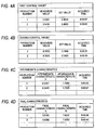
- Figs. 4A and 4B show examples of control data stored in the control data storage DB 21 with respect to the control target devices 3 and 4.
- Figs. 4C and 4D show examples of data for the intermediate characteristics stored in the intermediate characteristic data storage DB 23 and the final characteristic data storage DB 25.
- production numbers shown in Figs 4A to 4D are serial numbers for the works 2 processed by the individual devices. As described above, since the works 2 are sometimes gathered, omitted, or put back in the middle of production, even the same production numbers in the individual devices do not always correspond to the same works 2. For example, the work 2 corresponding to production number 1 of the first control target does not always correspond to production number 1 of the second control target.
- the intermediate characteristics inspected by the intermediate characteristic measuring device 5 are the characteristics of the intermediate product in the middle of production, which are inspected before inspected by the final characteristic measuring device 6. Therefore, the intermediate characteristics do not always have the same values as those of the final characteristics. Besides, two types of intermediate characteristics and final characteristics are acquired in the embodiment, but one or three types or more are acceptable.
- the scheduler 12 associates various items of data with each other stored in the data storing part 11, decides the timing to extract the associated data, and decides the timing to switch the set values of the control values to control the control target devices 3 and 4 and to switch the specification limits of the intermediate characteristics in the intermediate characteristic measuring device 5. Furthermore, the scheduler 12 sends the decided timing to the specification limit generating part 13 and the control instructing part 17.
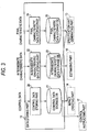
- Fig. 5 shows the schematic configuration of the scheduler 12.
- the scheduler 12 is configured to have a setting part 30, a control value extraction timing deciding part 31, an intermediate characteristic data extraction timing deciding part 32, a final characteristic data extraction timing deciding part 33, a control value switching timing deciding part 34, and a specification limit switching timing deciding part 35.
- the setting part 30 sets dead times Td1 to Td3 generated between the devices to acquire data, margin times Tm1 and Tm2, and time period Ts for the associated set, and sends them to the individual parts 31 to 35. Furthermore, it is fine that these values are acquired from a user through an input device such as a keyboard, or from a storage device, or from the other devices through a communication device.
- the first margin time Tm1 is a time period from the time to instruct switching the set values of the control values and the specification limits of the intermediate characteristics to the first acquired time of extraction from various items of data.
- the first margin time Tm1 is set so as to remove a time lag from the time to instruct switching the set value and the specification limit with respect to a device to the time to actually do the instruction with respect to the work 2, or remove a shift due to drawing a defective or to putting back a work.
- the second margin time Tm2 is a time period from the last acquired time of extraction from the intermediate characteristic data to the time to instruct switching the set value of the control value with respect to the first control target device 3.
- the second margin time Tm2 is set so as to consider processing time required to determine the set value to be switched.
- the margin times Tm1 and Tm2 and the time period Ts for a set are expressed by the number of the works 2.
- the time period Ts for a set is expressed by the number of the works 2
- the number of items of data included in each of the associated sets is constant, and thus the accuracy of statistics for each set can be nearly matched. Therefore, as in the case where any one of the devices 3 to 6 is once stopped and then again started, for example, the individual sets can be properly associated with each other even though the dead time is varied.
- a method to derive the values for the dead times Td1 to Td3 and the margin times Tm1 and Tm2 the following three methods are named. More specifically, first, a method to derive the values by calculation from the design value of the quality control system, that is, the time required for processing in each device, and the design value of the distance traveled and the rate of travel in moving works between the individual devices. Secondly, a method to derive the values by conducting test working to measure processing time and traveling time of works for actual measured values. Thirdly, a method to derive the values by conducting actual production working to measure processing time and traveling time of works for actual measured values.
- a method is named in which the initial set value before the quality control system is operated is derived from the first method and fine adjustments are done by the second or third method after operated.
- the intermediate characteristics inspected by the intermediate characteristic measuring device 5 are the characteristics of the intermediate product in the middle of production, which are inspected before inspected by the final characteristic measuring device 6. Therefore, the intermediate characteristics are not always the same values as those of the final characteristics. Moreover, two types of intermediate characteristics and final characteristics are acquired in the embodiment, but one or three types or more are acceptable.
- the scheduler 12 associates various items of data stored in the data storing part 11 with each other, decides the timing to extract the associated data, and decides the timing to switch the set values of the control values for controlling the control target devices 3 and 4 and to switch the specification limits of the intermediate characteristics in the intermediate characteristic measuring device 5. Furthermore, the scheduler 12 sends the decided timing to individual blocks 13, 14, 16 and 17.
- Fig. 5 shows the schematic configuration of the scheduler 12.
- the scheduler 12 is configured to have the setting part 30, the control value extraction timing deciding part 31, the intermediate characteristic extraction timing deciding part 32, the final characteristic extraction timing deciding part 33, the control value switching timing deciding part 34, and the specification limit switching timing deciding part 35.
- the settingpart 30 sets the dead times Td1 to Td3 generated between the devices to acquire data, the margin times Tm1 and Tm2, and the time period Ts for the associated sets, and sends them to the individual parts 31 to 35. Moreover, it is fine that these values are acquired from a user through an input device such as a keyboard, or from a storage device, or from the other devices through a communication device. Besides, it is acceptable to express the margin times Tm1 and Tm2 and the time period Ts for the sets by the number of intermediate products.
- the first margin time Tm1 is a time period from the time to instruct switching the set value of the control value and the specification limit of the intermediate characteristic to the first acquired time of extraction from various items of data.
- the first margin time Tm1 is set so as to remove a time lag from the time to instruct switching the set value and the specification limit with respect to a device to the time to actually do the instruction with respect to the work 2, or remove a shift due to drawing a defective or to putting back a work.
- the second margin time Tm2 is a time period from the last acquired time of extraction from the intermediate characteristic data to the time to instruct switching the set value of the control value with respect to the first control target device 3.
- the second margin time Tm2 is set so as to consider processing time required to determine the set value to be switched.
- a method to derive the values for the dead times Td1 to Td3 and the margin times Tm1 and Tm2 the following three methods are named. More specifically, first, a method to derive the values by calculation from the design value of the quality control system, that is, the time required for processing in each device, and the design value of the distance traveled and the rate of travel in moving works between the individual devices. Secondly, a method to derive the values by conducting test working to measure processing time and traveling time of works for actual measured values. Thirdly, a method to derive the values by conducting actual production working to measure processing time and traveling time of works for actual measured values.
- a method is named in which the initial set value before the quality control system is operated is derived from the first method and fine adjustments are done by the second or third method after operated.
- the control value extraction timing deciding part 31 decides the control value extraction timing that is the timing to extract the measurement value of the control value from each item of the control data. First, it acquires the first dead time Td1, the first margin time Tm1, and the time period Ts for a set from the setting part 30, and acquires operation start time T0 that starts the operation of the scheduler 12 and switching instruction time Ti (i is an integer equal to or greater than 1) that instructs switching the set value of the control value from the control value switching timing deciding part 34. Moreover, hereinafter, the operation start time and the switching instruction time are combined to Ti (i is an integer equal to or greater than 0).
- the control value extraction timing deciding part 31 decides the time from the time Ti + Tm1 that the first margin time Tm1 is added to the operation start time or the switching instruction time Ti to the time period Ts' for a set as a first control value extraction timing. Then, it decides the time from the time Ti + Tm1 + Td1 that the first dead time Td1 is added to the start time Ti + Tm1 for the first control value extraction timing to the time period Ts for a set as a second control value extraction timing. Besides, the control value extraction timing deciding part 31 sends the start time Ti + Tm1 + Td1 for the second control value extraction timing to the intermediate characteristic extraction timing deciding part 32.
- the intermediate characteristic extraction timing deciding part 32 decides the intermediate characteristic extraction timing that is the timing to extract the intermediate characteristics from the intermediate characteristic data. First, it acquires the second dead time Td2 and the time period Ts for a set from the setting part 30, and acquires the start time Ti + Tm1 + Td1 for the second control value extraction timing from the control value extraction timing deciding part 31.
- the intermediate characteristic extraction timing deciding part 32 decides the time from the time Ti + Tm1 + Td1 + Td2 that the second dead time Td2 is added to the start time Ti + Tm1 + Td1 for the second control value extraction timing to the time period Ts for a set as the intermediate characteristic extraction timing. Furthermore, the intermediate characteristic extraction timing deciding part 32 sends the start time Ti + Tm1 + Td1 + Td2 for the intermediate characteristic extraction timing to the final characteristic extraction timing deciding part 33 as well as sends termination time Ti + Tm1 + Td1 + Td2 + Ts for the intermediate characteristic extraction timing to the control value switching timing deciding part 34.
- the final characteristic extraction timing deciding part 33 decides the final characteristic extraction timing that is the timing to extract the final characteristics from the final characteristic data. First, it acquires the third dead time Td3 and the time period Ts for a set from the setting part 30, and acquires the start time Ti + Tm1 + Td1 + Td2 for the intermediate characteristic extraction timing from the intermediate characteristic extraction timing deciding part 32.
- the final characteristic extraction timing deciding part 33 decides the time from the time Ti + Tm1 + Td1 + Td2 + Td3 that the third dead time Td3 is added to the start time Ti + Tm1 + Td1 + Td2 for the intermediate characteristic extraction timing to the time period Ts for a set as the final characteristic extraction timing. Moreover, the final characteristic extraction timing deciding part 33 sends the termination time Ti + Tm1 + Td1 + Td2 + Td3 + Ts for the final characteristic extraction timing to the specification limit switching timing deciding part 35.
- the control value switching timing deciding part 34 decides first and second control value switching timings that are the timing to switch the set values of the control values in the first and second control target devices 3 and 4. First, it acquires the first dead time Td1 and the second margin time Tm2 from the setting part 30, and acquires the termination time Ti + Tm1 + Td 1 + Td2 + Ts for the intermediate characteristic extraction timing from the intermediate characteristic extraction timing deciding part 32.
- the control value switching timing deciding part 34 decides the time Ti + Tm1 + Td1 + Td2 + Ts + Tm2 that the second margin time Tm2 is added to the termination time Ti + Tm1 + Td1 + Td2 + Ts for the intermediate characteristic extraction timing as the first control value switching timing, and decides the time Ti + Tm1 + 2 ⁇ Td1 + Td2 + Ts + Tm2 that the first dead time Td1 is added to the first control value switching timing Ti + Tm1 + Td1 + Td2 + Ts + Tm2 as the second control value switching timing.
- control value switching timing deciding part 34 sends the first control value switching timing Ti + Tm1 + Td1 + Td2 + Ts + Tm2 as the switching instruction time Ti next time to the control value extraction timing deciding part 31 and the specification limit switching timing deciding part 35.
- the specification limit switching timing deciding part 35 decides the specification limit switching timing that is the timing to switch the specification limit of the intermediate characteristic in the intermediate characteristic measuring device 5. First, it acquires the first and second dead times Td1 and Td2 from the setting part 30, and acquires the termination time Ti + Tm1 + Td1 + Td2 + Td3 + Ts for the final characteristic extraction timing from the final characteristic extraction timing deciding part 33, and acquires the switching instruction time Ti from the control value switching timing deciding part 34.
- the specification limit switching timing deciding part 35 specifies the switching instruction time Ti that appears first after the termination time Ti + Tm1 + Td1 + Td2 + Td3 + Ts for the final characteristic extraction timing, and decides the time Ti + Td1 + Td2 that the specified switching instruction time Ti is added to the first and second dead times Td1 and Td2 as the specification limit switching timing.
- Fig. 6 shows the exemplary timing operation of the scheduler 12 of the configuration.
- areas denoted by n to (n + 3) are sets associated between the individual devices 3 to 6.
- the first dead time Td1 is two seconds
- the second dead time Td2 is four seconds
- the third dead time Td3 is 20 seconds.
- the first and second margin times Tm1 and Tm2 are 0.75 second
- the time period Ts for a set is 4.5 seconds
- the control data can be extracted by the intermediate characteristic extraction timing, and the intermediate characteristic data can be extracted at the intermediate characteristic extraction timing.
- the set values of the control values for the control target devices 3 and 4 are determined based on the extracted control data and the intermediate characteristic data, and control instructions to switch to the determined set values are sent to the control target devices 3 and 4.
- Tn + 1 the switching instruction item
- the intermediate characteristic data can be extracted by the final characteristic extraction timing, and the final characteristic data can be extracted at the final characteristic extraction timing. Therefore, as described above, the specification limits of the intermediate characteristics are determined based on the extracted intermediate characteristic data and final characteristic data, and a control instruction to switch to the determined specification limits are sent to the intermediate characteristic measuring device 5.
- the extraction of the intermediate characteristic data and the final characteristic data and the switching of the specification limits are repeated.
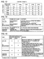
- Fig. 14 shows the types of the improper acquired data generated in general production sites, and the cause and contents. As shown in the drawing, as the types of the improper acquired data, 'outlier', 'remeasurement', "putting back', and 'removed product' are named.
- the 'outlier' shows the case where the measurement value is greatly deviated from the normal value.
- the data distribution is formed nearly in the normal distribution that data gathers close to the mean value. Therefore, when the outlier is included ina set as the acquired data, it isdifficult to properly estimate the data distribution of the set because the outlier greatly influences it.
- the 'remeasurement' shows the case where a device fails to measure, for example, and thus again measures the same work 2.
- multiple measurement values exist for the same work 2, and the measurement value before remeasurement is highly likely to be abnormal. Therefore, when the measurement value before remeasurement is included as the acquired data in a set, it is difficult to properly estimate the data distribution of the set as similar to the case of the outlier.
- the 'putting back' shows the case where the work 2 determined as out-of-specification by the intermediate characteristic measuring device 5, for example, is put back to the process steps done by the second control target device 4.
- the work 2 determined as out-of-specification by the intermediate characteristic measuring device 5, for example, is put back to the process steps done by the second control target device 4.
- the 'removed product' shows the case where the work 2 determined as out-of-specification by the intermediate characteristicmeasuring device 5, for example, is removed right after its inspection.
- the work 2 to be removed there are the acquired data of the intermediate characteristic measuring device 5 and the acquired data of the first and second control target devices 3 and 4 in the previous process steps of the intermediate characteristic measuring device 5.
- the acquired data of the final characteristic measuring device 6 there is not the acquired data of the final characteristic measuring device 6 in the subsequent process steps of the intermediate characteristic measuring device 5. Therefore, relating to the sets associated between devices 3 to 6, the works 2 corresponding to the acquired data included in each set are varied between the sets relating to the first and second control target devices 3 and 4 and the intermediate characteristic measuring device 5, and the set relating to the final characteristic measuring device 6.
- the improper acquired data is removed out of the set.
- whether to remove the acquired data depends on which types the improper acquired data is and which of the previous process steps or the subsequent process steps the set is included.
- the individual devices 3 to 6 add improper type information that indicates the types of improper data to the acquired data, and sends it to the quality control apparatus 10 to store it in the data storing part 11. Furthermore, the quality control apparatus 10 stores a table shown in Fig. 15 in a storing part, not shown. This table stores the types of the improper acquired data, and information that indicates whether the acquired data is invalid data to be removed or valid data to be left when the sets for the previous process steps or the subsequent process steps are associated.
- the scheduler refers to the table shown in Fig. 15 and improper type information stored in the data storing part 11, and removes invalid data out of the acquired data to associate the sets of the acquired data. Therefore, since the improper acquired data can be removed in accordance with the types and which of the previous process steps or the subsequent process steps the data is associated, the statistical processes can be conducted accurately. In addition, when the acquired data does not fall in the improper data, it is processed as valid data. Besides, when the acquired data falls in multiple types of improper data, it is processed as invalid data when it is at least one type fallen in invalid data.
- the specification limit generating part 13 extracts a set of the intermediate characteristic data from the intermediate characteristic data storage DB 23 based on the intermediate characteristic extraction timing decided by the scheduler 12, extracts a set of the final characteristic data from the final characteristic data storage DB 25 based on the final characteristic extraction timing decided by the scheduler 12, and generates the specification limits of the intermediate characteristics based on the extracted set. Furthermore, the specification limit generating part 13 sends the generated specification limits to the intermediate characteristic measuring device 5 based on the specification limit switching timing decided by the scheduler 12.
- Figs. 7A and 7B show the operation of generating the specification limits.
- the mean valueX - and the standard deviation ⁇ relating to the distribution of the extracted final characteristic A are determined.
- the mean value Xa - and the standard deviation ⁇ a relating to the distribution of the extracted intermediate characteristic A are determined.
- the operation of generating the specification limits are repeated with respect to the intermediate characteristics such as the intermediate characteristic Bother than the intermediate characteristic A, and thus the specification limit for each is generated. Moreover, when the specification limit is only the upper limit or the lower limit, the specification limit can be generated similarly.
- the specification limits of the intermediate characteristics are stricter than the specification limits of the final characteristics. More specifically, the specification limit generating part 13 desirably adjusts the specification limits generated in accordance with the equations based on the safety factor.
- the safety factor is three to four experimentally, but it is calculated based on the tolerance design proposed in quality engineering in recent years (for example, seethe second and third chapters in Non-patent Document 1).
- the tolerance design is a method in which quality is converted by the loss function to calculate the optimum tolerance that minimizes the loss.
- ⁇ is the safety factor
- A is the discard cost when a defective is removed in the intermediate inspection
- A0 is the discard cost when a defective is removed in the final inspection.
- the above equation is heldbecause the intermediate characteristic is adesired target characteristic as it is closer to the target value as much as possible.
- the specification limit of the intermediate characteristic is only the upper specification limit Sua between the equations above.
- the impact creating part 14 creates an impact that indicates how the intermediate characteristics are varied when the control values are switched based on a request from the estimating part 16, sends the created impact to the estimating part 16, and stores it in the impact storage DB 15.
- the impact creating part 14 sets the initial value for an impact beforehand before the scheduler 12 is operated, and stores it in the impact storage DB 15.
- the initial value for an impact can be determined by calculating a change in the mean value of the controllable factor (control value) and a variation in the mean value and in variations (variance and standard deviation) of the intermediate characteristics with respect to the controllable factor.
- Fig. 8 shows the process operation of the impact creating part 14 after the scheduler 12 is operated.
- two sets of the control data relating to the first control target device 3 (control target 1) are extracted from the control data storage DB 21 (hereinafter, it is called 'first control data').
- two sets of the control data relating to the second control target device 4 (control target 2) are extracted from the control data storage DB 21 (hereinafter, it is called 'second control data').
- two sets of the intermediate characteristic are extracted from the intermediate characteristic data storage DB 23 (S30).
- the mean value of the set of the intermediate characteristic extracted at this time is calculated (S31), and it is determined whether the difference between the calculated mean value and the estimated value of the mean value of the intermediate characteristic acquired from the estimating part 16 is greater than a predetermined value D (S32) .
- a predetermined value D D
- the process operation of the impact creating part 14 is ended.
- a variation this time with respect to that at the previous time is calculated relating to the mean value and variance of the intermediate characteristic (S34). More specifically, the mean value and variance relating to the set of the intermediate characteristic A extracted based on the intermediate characteristic extraction timing at the previous time are Y (n - 1) and Z (n - 1), respectively, and the mean value and variance relating to the set of the intermediate characteristic A extracted based on the intermediate characteristic extraction timing this time are Y (n) and Z (n), respectively.
- the procedures are used to also determine an impact caused by the second control data and an impact on the other intermediate characteristic B. More specifically, in practice, the following is to be created: impacts on the mean value and variance of the intermediate characteristic A by the first control data, impacts on the mean value and variance of the intermediate characteristic A by the second control data, impacts on the mean value and variance of the intermediate characteristic B by the first control data, and impacts on the mean value and variance of the intermediate characteristic B by the second control data.
- the created impacts are sent to the estimating part 16, the impacts stored in the impact storage DB 15 are updated (S36), and the operation of the impact creating part 14 is ended.
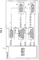
- Fig. 9 shows the schematic configuration of the estimating part 16.
- the estimating part 16 is configured to have an intermediate characteristic estimating part (intermediate characteristic estimating module) 40, a defective estimating part (defective number estimating module) 41, and an estimated value evaluating part (variation deciding module) 42.
- the intermediate characteristic estimating part 40 uses the impact read out of the impact storage DB 15 to estimate a variation in the mean value or the standard deviation (variance) of the intermediate characteristic when the set value of the control value is switched.
- the defective estimating part 41 estimates the number of defectives when the distribution of the intermediate characteristic is varied by the variation estimated by the intermediate characteristic estimating part 40, and evaluates by the sum of the number of individual defectives.
- the estimated value evaluating part 42 determines a variation in the set value of the control value when the number of defectives is the minimum, and sends it to the control instructing part 17.
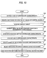
- Fig. 10 shows the process operation of the estimating part 16 of the configuration.
- the intermediate characteristic estimating part 40 extracts a set of the intermediate characteristic data from the intermediate characteristic data storage DB 23 of the data storing part 11 based on the intermediate characteristic extraction timing decided by the scheduler 12 (S40).
- the intermediate characteristic estimating part 40 creates a switching pattern that is a combination of the switching amount of the set values of the control values relating to the individual control target devices 3 and 4 (S41).
- Fig. 11 shows an example of the switching pattern in a table form.
- the switching pattern is expressed by a two-dimensional table as shown in Fig. 11 .
- the number of the switching amounts for the set values of the control values can be experimentally decided from the switching margin possibly effective and the tolerance of the switching margin, but it can be decided by any manners.
- the number of the switching amounts is five in the control target 1 (control target device 3) and the control target 2 (control target device 4). Furthermore, the switching margin for the control target 1 is 0.003, and the switching margin for the control target 2 is 0.005. Moreover, as shown in Fig. 11 , 0.000, that is, 'not switching' is included in the switching amount in the embodiment, but it is not necessarily included.
- the mean value of the intermediate characteristic or the estimated value of the standard deviation when the set values of the control values are switched is determined with respect to each of the switching patterns, and thus the estimated value table shown in Fig. 11 is completed. More specifically, the current impact is acquired from the impact storage DB 15 (S42), and the acquired impact is multiplied by the switching margin (switching amount) for the set value of the control value. Therefore, the mean value or the variation in the variance of the intermediate characteristic is determined when the set value of the control value is switched.
- the variation is added to the mean value or variance of the extracted current intermediate characteristic.
- the variance the square root is taken after this and converted to standard deviation.
- the estimated value of the mean value or the standard deviation of the intermediate characteristic is determined for each combination of the switching amount for the set values of the control values for the control target, and the estimated value table shown in Fig. 11 is competed (S43).
- Fig. 11 shows the estimated value Xa, i, j for the mean value.
- the switching margin for the set value of the control value is ⁇
- the mean value of the intermediate characteristic A is X -
- the standard deviation of the intermediate characteristic A is ⁇
- an impact for the mean value of the intermediate characteristic A is k1
- an impact for the variance of the intermediate characteristic A is k2.
- the defective estimating part 41 uses the estimated value determined by the intermediate characteristic estimating part 40 to create the distribution of the intermediate characteristic after switched for every switching pattern, and estimates the number of defectives for the intermediate characteristic. More specifically, the specification criteria (specification limits) are moved by the change in the created distribution of the intermediate characteristic (S44), and it is determined whether elements (individual intermediate characteristics) included in the extracted set are passed or failed (S45).
- the estimated value evaluating part 42 sums the number of defectives for the individual intermediate characteristics determined by the defective estimating part 41 (S46), and selects the switching pattern that the summed number of defectives is the minimum (S47).
- S46 the number of defectives for the individual intermediate characteristics determined by the defective estimating part 41
- S47 the switching pattern that the summed number of defectives is the minimum
- the NG flag is indicated as bit data as 1 (ON) when it is given, whereas 0 (OFF) when it is not given.
- the logical OR (OR) is taken with respect to the NG flags of the intermediate characteristics A to C for every production number, and the flags are counted to determine the sum of the number of defectives.
- the estimated value evaluating part 42 calculates the total sum of the number of defectives (the total number of defectives) for every switching pattern, and thus a total defective number table corresponding to the estimated value table is created.
- Fig. 13 shows an example of the total defective number table, which corresponds to the estimated value table shown in Fig. 11 .
- the estimated value evaluating part 42 refers to the total defective number table to select the switching pattern that the total number of defectives is the minimum. In the case of Fig.
- a combination that the switching amount for the set value of the control value of the control target 1 (control target device 3) being 0.003 with the switching amount for the set value of the control value of the control target 2 (control target device 4) being 0.010 is the minimum by the total number of defectives being 15, and thus this switching pattern is selected.
- the estimated value evaluating part 42 sends the selected switching pattern (the combination of the switching amounts) to the control instructing part 17 (S48) . Furthermore, it sends the estimated value of the intermediate characteristic corresponding to the selected switching pattern to the impact creating part 14. After that, the operation of the estimating part 16 is ended.
- the switching pattern that the total number of defectives is the minimum is selected, and consequently it can be considered that the switching amount for one of control targets 1 and 2 or for both is 0.000, that is, switching is unnecessary. In this case, sending the switching amount for this control target can be omitted to the control instructing part 17.
- the control instructing part 17 acquires the combination for every control target relating to the switching pattern selected by the estimated value evaluating part 42, that is, the switching amounts for the set values of the control values, switches the set value of the control value of each of the control target devices 3 and 4 based on the acquired switching pattern, and sends the switched set values as control instructions to the control target devices 3 and 4.
- the scheduler 12 desirably adjusts these time lags as well to decide the association of data and timing.
- the data storing part 11 stores the acquired time in the embodiment, but it is fine that it receives the measured time that is the time measured by the individual devices 3 to 6 from each device for storing.
- the scheduler 12 is to use the measured time for association.
- control target devices 3 and 4 are used in the embodiment, but a single control target device can be used, and the control target device and the intermediate characteristic measuring device can be further increased.
- each block of the quality control apparatus 10 is configured of hardware logic and is implemented by software with a CPU as below.
- the quality control apparatus 10 has a CPU which executes instructions of a control program for implementing each function, a ROM which stores the program, a RAM which runs the program, and a storage device (recording medium) such as memory which stores the program and various items of data.
- the obj ect of the invention can also be achieved in which a recording medium that the program codes of the control program of the quality control apparatus 10 (an execute form program, an intermediate code program, and a source program), which is software for implementing the functions, are readable by a computer is supplied to the quality control apparatus 10 and the computer (or the CPU or MPU) reads the program codes recorded in the recording medium for execution.
- tapes such as magnetic tape and cassette tape
- disks including magnetic disks such as a flexible disk and a hard drive
- optical disks such as CD-ROM, MO, MD, DVD and CD-R
- cards such as an IC card (including a memory card) and an optical card
- semiconductor memory such as mask ROM, EPROM, EEPROM and flash ROM.
- the quality control apparatus 10 is configured to be connectable to a communication network and the program codes are supplied through the communication network.
- the communication network is not defined particularly.
- the following canbe used: the Internet, an intranet, an extranet, LAN, ISDN, VAN, a CATV communications network, a virtual private network, a telephone network, a mobile communications network, and a satellite communications network.
- transmission media to configure the communication networks are not limited particularly.
- cables such as IEEE 1394, USB, electric power line transmission, cable TV lines, telephone lines, and ADSL lines, or radio such as infrared rays including IrDA or remote control, Bluetooth (trade mark), 802.11 radio, HDR, mobile telephone networks, satellite connections, and terrestrial digital networks.
- radio such as infrared rays including IrDA or remote control, Bluetooth (trade mark), 802.11 radio, HDR, mobile telephone networks, satellite connections, and terrestrial digital networks.
- the invention can be implemented in the forms of carrier waves that implement the program codes to be electronically transmitted, or of data signal rows.
- the quality control apparatus according to the invention can be applied to devices that control various processes to maintain proper conditions such as control over household electrical products, in addition to manufacturing processes.
Landscapes
- Engineering & Computer Science (AREA)
- Business, Economics & Management (AREA)
- General Physics & Mathematics (AREA)
- Quality & Reliability (AREA)
- Physics & Mathematics (AREA)
- Entrepreneurship & Innovation (AREA)
- Economics (AREA)
- Human Resources & Organizations (AREA)
- Strategic Management (AREA)
- Marketing (AREA)
- Operations Research (AREA)
- Game Theory and Decision Science (AREA)
- Tourism & Hospitality (AREA)
- Educational Administration (AREA)
- General Business, Economics & Management (AREA)
- Development Economics (AREA)
- Theoretical Computer Science (AREA)
- Automation & Control Theory (AREA)
- General Factory Administration (AREA)
- Management, Administration, Business Operations System, And Electronic Commerce (AREA)
Claims (11)
- Vorrichtung (10) zur Qualitätskontrolle, die einen Herstellungsprozess steuert, um aus Werkstücken (2) Produkte (7) mit einer vorherbestimmten Qualität herzustellen, wobei die Vorrichtung umfasst:ein Speichermodul (11), das Messdaten sammelt, die von einer Mehrzahl an Messvorrichtungen (3, 4, 5, 6) gemessen wurden, die in dem Herstellungsprozess angeordnet sind, und die gesammelten Messdaten zusammen mit Zeitdaten speichert, die angeben, wann die jeweiligen Messdaten gemessen oder gesammelt wurden; undein Assoziierungsmodul (12), das ermittelt, ob eine Mehrzahl an Datensätzen (n, n+1, n+2, n+3) miteinander assoziiert ist oder nicht miteinander assoziiert ist, wobei die Mehrzahl an Datensätzen (n, n+1, n+2, n+3) bezüglich der Zeitdaten und einer zwischen den Messvorrichtungen generierten Totzeit (Td1, Td2, Td3) miteinander assoziiert ist oder nicht,wobei jeder der Mehrzahl an Datensätzen Messdaten enthält, die von einer jeweiligen der Mehrzahl an Messvorrichtungen gemessen wurden,wobei jeder der Mehrzahl an Datensätzen Elemente der Messdaten enthält, die von der jeweiligen der Mehrzahl an Messvorrichtungen für eine Gruppe von Werkstücken, die eine gegebene Anzahl an Werkstücken enthält, gemessen wurden,wobei die Mehrzahl an Datensätzen, die assoziiert werden, zu der gleichen Gruppe von Werkstücken gehört,wobei das Speichermodul von einer Zwischencharakteristikmessvorrichtung (5) gemessene Zwischencharakteristikdaten eines Zwischenprodukts und von einer Endcharakteristikmessvorrichtung (6) gemessene Endcharakteristikdaten eines fertiggestellten Produkts sammelt und speichert; undwobei die Vorrichtung ferner aufweist:ein Spezifikationsgrenzenerzeugungsmodul (13), das eine in der Zwischencharakteristikmessvorrichtung eingestellte Zwischencharakteristikspezifikationsgrenze auf der Basis einer Datenverteilung der in dem Speichermodul gespeicherten Endcharakteristikdaten sowie eine in der Endcharakteristikmessvorrichtung eingestellte Endcharakteristikspezifikationsgrenze erzeugt; undein Spezifikationsgrenzeneinstellsteuermodul, das die Zwischencharakteristikmessvorrichtung so steuert, dass sie die von dem Spezifikationsgrenzenerzeugungsmodul erzeugte Zwischencharakteristikspezifikationsgrenze einstellt.
- Vorrichtung zur Qualitätskontrolle nach Anspruch 1, bei der das Assoziierungsmodul, wenn inkorrekte Messdaten in den miteinander zu assoziierenden Messdaten enthalten sind, das Assoziieren der inkorrekten Messdaten mit den Messdaten, die die von der anderen Messvorrichtung gemessenen Messdaten sind und den inkorrekten Messdaten entsprechen, stoppt.
- Vorrichtung zur Qualitätskontrolle nach Anspruch 2, bei der das Assoziierungsmodul, wenn ein Zwischenprodukt bei einem bestimmten Prozessschritt in den Herstellungsprozess zurückgebracht wird, das Assoziieren der Messdaten der Messvorrichtung bezüglich des Zwischenprodukts auf einer Zulaufseite des Prozessschritts mit Messdaten der Messvorrichtung bezüglich des Zwischenprodukts an dem Prozessschritt und auf dessen Ablaufseite stoppt.
- Vorrichtung zur Qualitätskontrolle nach Anspruch 2, bei der das Assoziierungsmodul, wenn ein Zwischenprodukt bei einem bestimmten Prozessschritt aus dem Herstellungsprozess entfernt wird, das Assoziieren von Messdaten der Messvorrichtung auf einer Ablaufseite des Prozessschritts mit Messdaten der Messvorrichtung bezüglich des Zwischenprodukts an dem Prozessschritt und auf dessen Zulaufseite stoppt.
- Vorrichtung zur Qualitätskontrolle nach Anspruch 1, bei der das Spezifikationsgrenzenerzeugungsmodul die Zwischencharakteristikspezifikationsgrenze auf der Basis einer Differenz zwischen einem Mittelwert der Datenverteilung der Endcharakteristikdaten und der Endcharakteristikspezifikationsgrenze erzeugt.
- Vorrichtung zur Qualitätskontrolle nach Anspruch 5, bei der das Spezifikationsgrenzenerzeugungsmodul die Zwischencharakteristikspezifikationsgrenze so erzeugt, dass ein Verhältnis einer Differenz zwischen einem Mittelwert der Datenverteilung der in dem Speichermodul gespeicherten Zwischencharakteristikdaten und der Zwischencharakteristikspezifikationsgrenze zu der Differenz zwischen dem Mittelwert der Datenverteilung der Endcharakteristikdaten und der Endcharakteristikspezifikationsgrenze koinzident gemacht wird mit einem Verhältnis eines Variationswerts der Datenverteilung der Zwischencharakteristikdaten zu einem Variationswert der Datenverteilung der Endcharakteristikdaten.
- Vorrichtung zur Qualitätskontrolle nach Anspruch 1, bei der das Spezifikationsgrenzenerzeugungsmodul außerdem die Zwischencharakteristikspezifikationsgrenze auf der Basis eines Sicherheitsfaktors erzeugt.
- Vorrichtung zur Qualitätskontrolle nach Anspruch 7, bei der der Sicherheitsfaktor berechnet wird auf der Basis von Ausschusskosten, wenn das fertiggestellte Produkt auf der Basis der Endcharakteristikspezifikationsgrenze entfernt wird, und von Ausschusskosten, wenn das Zwischenprodukt auf der Basis der Zwischencharakteristikspezifikationsgrenze entfernt wird.
- Vorrichtung zur Qualitätskontrolle nach Anspruch 1, bei der das Spezifikationsgrenzenerzeugungsmodul eine nachfolgende Spezifikationsgrenze erzeugt, indem sie die Zwischencharakteristikdaten und die Endcharakteristikdaten verwendet, die von dem Speichermodul gesammelt wurden, nachdem eine gegebene Zeitspanne ab dem Zeitpunkt verstrichen ist, zu dem das Spezifikationsgrenzeneinstellsteuermodul die Zwischencharakteristikmessvorrichtung gesteuert hatte.
- Steuerverfahren zum Steuern eines Herstellungsprozesses, um aus Werkstücken (2) Produkte (7) mit einer vorherbestimmten Qualität herzustellen, wobei das Verfahren umfasst:Bereitstellen einer Vorrichtung (10) zur Qualitätskontrolle, die ein Speichermodul (11) und ein Assoziierungsmodul (12) umfasst;Sammeln, im Speichermodul, von Messdaten, die von einer Mehrzahl an Messvorrichtungen (3, 4, 5, 6) gemessen wurden, die in dem Herstellungsprozess angeordnet sind, und Speichern der gesammelten Messdaten zusammen mit Zeitdaten, die angeben, wann die jeweiligen Messdaten gemessen oder gesammelt wurden; undErmitteln, in dem Assoziierungsmodul (12), ob eine Mehrzahl an Datensätzen (n, n+1, n+2, n+3) miteinander assoziiert ist oder nicht miteinander assoziiert ist, wobei die Mehrzahl an Datensätzen (n, n+1, n+2, n+3) bezüglich der Zeitdaten und einer zwischen den Messvorrichtungen generierten Totzeit (Td1, Td2, Td3) miteinander assoziiert ist oder nicht,wobei jeder der Mehrzahl an Datensätzen Messdaten enthält, die von einer jeweiligen der Mehrzahl an Messvorrichtungen gemessen wurden,wobei jeder der Mehrzahl an Datensätzen Elemente der Messdaten enthält, die von der jeweiligen der Mehrzahl an Messvorrichtungen für eine Gruppe von Werkstücken, die eine gegebene Anzahl an Werkstücken enthält, gemessen wurden,wobei die Mehrzahl an Datensätzen, die assoziiert werden, zu der gleichen Gruppe von Werkstücken gehört,wobei die Messdaten von einer Zwischencharakteristikmessvorrichtung (5) gemessene Zwischencharakteristikdaten eines Zwischenprodukts und von einer Endcharakteristikmessvorrichtung (6) gemessene Endcharakteristikdaten eines fertiggestellten Produkts sammelt und speichert, undwobei das Verfahren ferner aufweist:Erzeugen einer in der Zwischencharakteristikmessvorrichtung eingestellten Zwischencharakteristikspezifikationsgrenze auf der Basis einer Datenverteilung der in dem Speichermodul gespeicherten Endcharakteristikdaten sowie einer in der Endcharakteristikmessvorrichtung eingestellten Endcharakteristikspezifikationsgrenze; undSteuern der Zwischencharakteristikmessvorrichtung so, dass sie die Zwischencharakteristikspezifikationsgrenze einstellt.
- Computer-lesbares Speichermedium, auf dem ein Programm zur Qualitätskontrolle gespeichert ist, das einen Computer veranlasst, das Steuerverfahren gemäß Anspruch 10 auszuführen.
Priority Applications (1)
| Application Number | Priority Date | Filing Date | Title |
|---|---|---|---|
| EP10008746A EP2256696B1 (de) | 2004-04-30 | 2005-04-28 | Qualitätskontrollvorrichtung und Kontrollverfahren für diese Vorrichtung und Aufzeichnungsmedium, auf das ein Qualitätskontrollprogramm aufgezeichnet ist |
Applications Claiming Priority (4)
| Application Number | Priority Date | Filing Date | Title |
|---|---|---|---|
| JP2004136409 | 2004-04-30 | ||
| JP2004136409 | 2004-04-30 | ||
| JP2004306159 | 2004-10-20 | ||
| JP2004306159A JP3705296B1 (ja) | 2004-04-30 | 2004-10-20 | 品質制御装置およびその制御方法、品質制御プログラム、並びに該プログラムを記録した記録媒体 |
Related Child Applications (1)
| Application Number | Title | Priority Date | Filing Date |
|---|---|---|---|
| EP10008746A Division-Into EP2256696B1 (de) | 2004-04-30 | 2005-04-28 | Qualitätskontrollvorrichtung und Kontrollverfahren für diese Vorrichtung und Aufzeichnungsmedium, auf das ein Qualitätskontrollprogramm aufgezeichnet ist |
Publications (3)
| Publication Number | Publication Date |
|---|---|
| EP1591966A2 EP1591966A2 (de) | 2005-11-02 |
| EP1591966A3 EP1591966A3 (de) | 2006-02-01 |
| EP1591966B1 true EP1591966B1 (de) | 2016-06-01 |
Family
ID=34941081
Family Applications (2)
| Application Number | Title | Priority Date | Filing Date |
|---|---|---|---|
| EP10008746A Expired - Lifetime EP2256696B1 (de) | 2004-04-30 | 2005-04-28 | Qualitätskontrollvorrichtung und Kontrollverfahren für diese Vorrichtung und Aufzeichnungsmedium, auf das ein Qualitätskontrollprogramm aufgezeichnet ist |
| EP05252652.2A Expired - Lifetime EP1591966B1 (de) | 2004-04-30 | 2005-04-28 | Vorrichtung zur Qualitätskontrolle und Verfahren dafür sowie Datenträger mit einem Programm zur Qualitätskontrolle |
Family Applications Before (1)
| Application Number | Title | Priority Date | Filing Date |
|---|---|---|---|
| EP10008746A Expired - Lifetime EP2256696B1 (de) | 2004-04-30 | 2005-04-28 | Qualitätskontrollvorrichtung und Kontrollverfahren für diese Vorrichtung und Aufzeichnungsmedium, auf das ein Qualitätskontrollprogramm aufgezeichnet ist |
Country Status (4)
| Country | Link |
|---|---|
| US (1) | US7324862B2 (de) |
| EP (2) | EP2256696B1 (de) |
| JP (1) | JP3705296B1 (de) |
| CN (1) | CN101893880A (de) |
Families Citing this family (27)
| Publication number | Priority date | Publication date | Assignee | Title |
|---|---|---|---|---|
| JP4552749B2 (ja) * | 2005-05-12 | 2010-09-29 | オムロン株式会社 | 検査基準設定装置及び方法、並びに、工程検査装置 |
| JP4337841B2 (ja) * | 2006-06-07 | 2009-09-30 | オムロン株式会社 | データ表示装置およびその制御方法、データ表示装置制御プログラム、ならびに該プログラムを記録した記録媒体 |
| US20090327023A1 (en) * | 2008-06-25 | 2009-12-31 | Nanji Chris | System for management and control of an enterprise |
| JP4905444B2 (ja) * | 2008-12-15 | 2012-03-28 | オムロン株式会社 | データ対応付け装置およびその制御方法、データ対応付け装置制御プログラム、ならびに該プログラムを記録した記録媒体 |
| US9323234B2 (en) * | 2009-06-10 | 2016-04-26 | Fisher-Rosemount Systems, Inc. | Predicted fault analysis |
| US20110040399A1 (en) * | 2009-08-14 | 2011-02-17 | Honeywell International Inc. | Apparatus and method for integrating planning, scheduling, and control for enterprise optimization |
| US9242386B2 (en) * | 2010-06-18 | 2016-01-26 | The Gillette Company | Use of printed circuit board, electronic component, and semi-conductor assembly equipment for the assembly of razors and components thereof |
| JP5327239B2 (ja) * | 2011-01-31 | 2013-10-30 | オムロン株式会社 | データ収集装置、並びに、該データ収集装置の制御方法および制御プログラム |
| JP5572194B2 (ja) * | 2012-09-21 | 2014-08-13 | 株式会社東芝 | 製造管理システム、製造管理方法、および製造管理プログラム |
| US9286585B2 (en) | 2012-10-26 | 2016-03-15 | International Business Machines Corporation | Automated data-driven closed-loop-feedback method for adaptive and comparative quality control in a discrete data aggregation environment |
| JP6264725B2 (ja) * | 2013-02-13 | 2018-01-24 | 株式会社ジェイテクト | 生産ラインにおける生産物の品質分析装置 |
| US10048670B2 (en) * | 2014-05-08 | 2018-08-14 | Beet, Llc | Automation operating and management system |
| US11625147B2 (en) | 2014-05-08 | 2023-04-11 | Beet, Inc. | Automation management interface with multiple asset display |
| JP5824550B1 (ja) * | 2014-05-13 | 2015-11-25 | 三菱電機インフォメーションシステムズ株式会社 | データ管理装置及びデータ管理プログラム |
| US9733629B2 (en) | 2014-07-21 | 2017-08-15 | Honeywell International Inc. | Cascaded model predictive control (MPC) approach for plantwide control and optimization |
| US10379503B2 (en) | 2014-07-21 | 2019-08-13 | Honeywell International Inc. | Apparatus and method for calculating proxy limits to support cascaded model predictive control (MPC) |
| DE112016005697T5 (de) * | 2016-01-15 | 2018-09-06 | Mitsubishi Electric Corporation | Vorrichtung, Verfahren und Programm zur Planerzeugung |
| US11188037B2 (en) * | 2016-03-24 | 2021-11-30 | Siemens Aktiengesellschaft | Controlling methods, control systems, and plants using semantic models for quality criteria or adaptation of control rules |
| KR20180054063A (ko) * | 2016-11-14 | 2018-05-24 | 주식회사 고영테크놀러지 | 검사체에 대한 양부 판정 조건을 조정하는 방법 및 장치 |
| US11366068B2 (en) | 2016-11-14 | 2022-06-21 | Koh Young Technology Inc. | Inspection apparatus and operating method thereof |
| US10466684B2 (en) | 2017-05-25 | 2019-11-05 | Honeywell International Inc. | Apparatus and method for adjustable identification of controller feasibility regions to support cascaded model predictive control (MPC) |
| JP7140468B2 (ja) | 2017-06-01 | 2022-09-21 | 株式会社日立製作所 | トレーサビリティシステムおよびトレーサビリティの方法 |
| US10908562B2 (en) | 2017-10-23 | 2021-02-02 | Honeywell International Inc. | Apparatus and method for using advanced process control to define real-time or near real-time operating envelope |
| SE542608C2 (en) * | 2018-08-27 | 2020-06-16 | Rise Res Institutes Of Sweden Ab | Method and system for enhancing traceability in a production line by creating a time-based fingerprint |
| US12164656B2 (en) * | 2018-12-20 | 2024-12-10 | Id Business Solutions, Inc. | Dynamic batch limit validation |
| JP7438723B2 (ja) * | 2019-11-15 | 2024-02-27 | 株式会社日立製作所 | 製造プロセスの適正化システムおよびその方法 |
| CN115705543B (zh) * | 2021-08-12 | 2025-07-25 | 长鑫存储技术有限公司 | 用于评估半导体设备生产能力的方法及其装置 |
Family Cites Families (19)
| Publication number | Priority date | Publication date | Assignee | Title |
|---|---|---|---|---|
| JP2562135B2 (ja) | 1986-11-06 | 1996-12-11 | トヨタ自動車株式会社 | トラツキング方法 |
| JPH03228531A (ja) | 1990-02-02 | 1991-10-09 | Sekisui Chem Co Ltd | 組立ライン管理システム |
| JP2635209B2 (ja) | 1990-11-22 | 1997-07-30 | 株式会社日立製作所 | プロセス制御方法及び装置 |
| JP3035089B2 (ja) | 1992-09-25 | 2000-04-17 | 松下電工株式会社 | プロセスの特性推定方法およびその装置ならびにその推定方法を用いたプロセスの監視方法およびプロセスの制御方法 |
| JPH07141005A (ja) | 1993-06-21 | 1995-06-02 | Hitachi Ltd | 半導体集積回路装置の製造方法および製造装置 |
| JP3325737B2 (ja) * | 1995-03-09 | 2002-09-17 | 本田技研工業株式会社 | 品質管理データ処理装置 |
| JPH09160982A (ja) | 1995-12-13 | 1997-06-20 | Fuji Xerox Co Ltd | 品質管理方法および品質管理システム |
| US6013915A (en) * | 1998-02-10 | 2000-01-11 | Philip Morris Incorporated | Process control by transient thermography |
| JP2000091178A (ja) | 1998-09-11 | 2000-03-31 | Sony Corp | 生産管理方法 |
| JP3411225B2 (ja) | 1998-09-18 | 2003-05-26 | トヨタ自動車株式会社 | フィードバック式加工条件補正方法および記録媒体 |
| JP3270023B2 (ja) | 1999-05-25 | 2002-04-02 | ニチハ株式会社 | 被加工物識別システム |
| US6574522B1 (en) * | 1999-09-24 | 2003-06-03 | General Electric Company | System and method of collecting statistically analyzing and graphically displaying quality control data for a manufacturing process |
| GB0024635D0 (en) | 2000-10-06 | 2000-11-22 | Ipr Ind Ltd | Method of monitoring the manufacture of a product from a workpiece |
| US6516280B2 (en) * | 2000-12-20 | 2003-02-04 | General Electric Company | Method and system for electronic recycle inventory tracking |
| JP4677679B2 (ja) | 2001-03-27 | 2011-04-27 | 株式会社デンソー | 製品の製造プロセスにおける特性調整方法 |
| JP4168639B2 (ja) | 2002-02-19 | 2008-10-22 | トヨタ自動車株式会社 | 生産進捗管理システム、生産進捗管理方法および生産進捗管理プログラム |
| DE10252605A1 (de) * | 2002-11-12 | 2004-06-24 | Infineon Technologies Ag | Verfahren, Vorrichtung, computerlesbarer Speicher und Computerprogramm-Element zum rechnergestützten Überwachen und Regeln eines Herstellungsprozesses |
| US6823287B2 (en) * | 2002-12-17 | 2004-11-23 | Caterpillar Inc | Method for predicting the quality of a product |
| US7444197B2 (en) * | 2004-05-06 | 2008-10-28 | Smp Logic Systems Llc | Methods, systems, and software program for validation and monitoring of pharmaceutical manufacturing processes |
-
2004
- 2004-10-20 JP JP2004306159A patent/JP3705296B1/ja not_active Expired - Lifetime
-
2005
- 2005-04-28 EP EP10008746A patent/EP2256696B1/de not_active Expired - Lifetime
- 2005-04-28 EP EP05252652.2A patent/EP1591966B1/de not_active Expired - Lifetime
- 2005-04-28 US US11/116,457 patent/US7324862B2/en not_active Expired - Lifetime
- 2005-04-30 CN CN2010102084982A patent/CN101893880A/zh active Pending
Also Published As
| Publication number | Publication date |
|---|---|
| EP2256696B1 (de) | 2012-12-19 |
| EP2256696A1 (de) | 2010-12-01 |
| JP2005339498A (ja) | 2005-12-08 |
| EP1591966A2 (de) | 2005-11-02 |
| CN101893880A (zh) | 2010-11-24 |
| EP1591966A3 (de) | 2006-02-01 |
| US7324862B2 (en) | 2008-01-29 |
| JP3705296B1 (ja) | 2005-10-12 |
| US20050246045A1 (en) | 2005-11-03 |
Similar Documents
| Publication | Publication Date | Title |
|---|---|---|
| EP1591966B1 (de) | Vorrichtung zur Qualitätskontrolle und Verfahren dafür sowie Datenträger mit einem Programm zur Qualitätskontrolle | |
| US7092863B2 (en) | Model predictive control (MPC) system using DOE based model | |
| US7493185B2 (en) | Quality prognostics system and method for manufacturing processes | |
| EP1986066B1 (de) | Vorrichtung und Verfahren zur Verarbeitung kombinierter Informationen, Programm und Aufzeichnungsmedium | |
| US20060218107A1 (en) | Method for controlling a product production process | |
| EP2477469A2 (de) | Verfahren zur Bestimmung eines Standardwertes und seines optimalen Wertes, Inspektionssystem für ein Substrat, auf welches Komponenten bestückt werden, Simulationsmethode und Simulationssystem | |
| CN101501658B (zh) | 服务器装置及服务器装置取得测定信息的方法 | |
| CN101911272A (zh) | 用于超声波键合的方法和设备 | |
| WO2010061716A1 (ja) | 標準作業時間計算装置、標準作業時間管理システム、標準作業時間計算方法、及び、そのプログラム | |
| JP5017176B2 (ja) | 製造指示評価支援システム、製造指示評価支援方法、および製造指示評価支援プログラム | |
| EP1865451B1 (de) | Datenanzeigevorrichtung und Steuerverfahren dafür, Datenverknüpfungsvorrichtung und Steuerverfahren dafür, Steuerprogramm für die Datenanzeigevorrichtung und Aufzeichnungsmedium mit darauf gespeichertem Programm | |
| KR101921805B1 (ko) | 운용 계획 작성 평가 장치 및 운용 계획 작성 평가 방법 | |
| JP7391656B2 (ja) | 射出成形システム | |
| KR101022230B1 (ko) | 디지털 팩토리에서의 최적 생산 시나리오 구축방법 | |
| JP3800244B2 (ja) | 品質制御装置およびその制御方法、品質制御プログラム、並びに該プログラムを記録した記録媒体 | |
| CN118003530B (zh) | 一种可降解薄膜生产线中冷却控制系统及方法 | |
| CN109074054A (zh) | 作业辅助装置、作业辅助方法以及作业辅助程序 | |
| CN109870641B (zh) | 印刷电路板生产方法及其半成品阻抗检测方法 | |
| JP2004246628A (ja) | 標準時間算出装置及びそれに用いる標準時間算出方法並びにそのプログラム | |
| JP3726840B2 (ja) | 品質制御装置およびその制御方法、品質制御プログラム、並びに該プログラムを記録した記録媒体 | |
| JP4905444B2 (ja) | データ対応付け装置およびその制御方法、データ対応付け装置制御プログラム、ならびに該プログラムを記録した記録媒体 | |
| KR20140148394A (ko) | 제조공정의 관리지원장치 | |
| CN114077950A (zh) | 质量相关性分析方法、质量预测方法及质量控制方法 | |
| JP4203774B2 (ja) | 選別率推定装置、選別率推定方法、プログラムおよび記録媒体 | |
| CN118469167A (zh) | 作业分析装置、作业分析系统、作业分析方法和存储介质 |
Legal Events
| Date | Code | Title | Description |
|---|---|---|---|
| PUAI | Public reference made under article 153(3) epc to a published international application that has entered the european phase |
Free format text: ORIGINAL CODE: 0009012 |
|
| AK | Designated contracting states |
Kind code of ref document: A2 Designated state(s): AT BE BG CH CY CZ DE DK EE ES FI FR GB GR HU IE IS IT LI LT LU MC NL PL PT RO SE SI SK TR |
|
| AX | Request for extension of the european patent |
Extension state: AL BA HR LV MK YU |
|
| PUAL | Search report despatched |
Free format text: ORIGINAL CODE: 0009013 |
|
| AK | Designated contracting states |
Kind code of ref document: A3 Designated state(s): AT BE BG CH CY CZ DE DK EE ES FI FR GB GR HU IE IS IT LI LT LU MC NL PL PT RO SE SI SK TR |
|
| AX | Request for extension of the european patent |
Extension state: AL BA HR LV MK YU |
|
| 17P | Request for examination filed |
Effective date: 20060331 |
|
| 17Q | First examination report despatched |
Effective date: 20060725 |
|
| 17Q | First examination report despatched |
Effective date: 20060727 |
|
| AKX | Designation fees paid |
Designated state(s): AT BE BG CH CY CZ DE DK EE ES FI FR GB GR HU IE IS IT LI LT LU MC NL PL PT RO SE SI SK TR |
|
| 17Q | First examination report despatched |
Effective date: 20060727 |
|
| APBK | Appeal reference recorded |
Free format text: ORIGINAL CODE: EPIDOSNREFNE |
|
| APBN | Date of receipt of notice of appeal recorded |
Free format text: ORIGINAL CODE: EPIDOSNNOA2E |
|
| RIN1 | Information on inventor provided before grant (corrected) |
Inventor name: SONO, MINEOC Inventor name: SUGIHARA SHIROC Inventor name: FUGII TORUC |
|
| APAV | Appeal reference deleted |
Free format text: ORIGINAL CODE: EPIDOSDREFNE |
|
| APBR | Date of receipt of statement of grounds of appeal recorded |
Free format text: ORIGINAL CODE: EPIDOSNNOA3E |
|
| APBT | Appeal procedure closed |
Free format text: ORIGINAL CODE: EPIDOSNNOA9E |
|
| REG | Reference to a national code |
Ref country code: DE Ref legal event code: R079 Ref document number: 602005049447 Country of ref document: DE Free format text: PREVIOUS MAIN CLASS: G07C0003000000 Ipc: G06Q0010060000 |
|
| GRAP | Despatch of communication of intention to grant a patent |
Free format text: ORIGINAL CODE: EPIDOSNIGR1 |
|
| RIN1 | Information on inventor provided before grant (corrected) |
Inventor name: FUGII TORU Inventor name: SONO MINEO Inventor name: SUGIHARA SHIRO |
|
| INTG | Intention to grant announced |
Effective date: 20151223 |
|
| RIC1 | Information provided on ipc code assigned before grant |
Ipc: G06Q 10/06 20120101AFI20151215BHEP Ipc: G07C 3/14 20060101ALI20151215BHEP |
|
| GRAS | Grant fee paid |
Free format text: ORIGINAL CODE: EPIDOSNIGR3 |
|
| GRAA | (expected) grant |
Free format text: ORIGINAL CODE: 0009210 |
|
| AK | Designated contracting states |
Kind code of ref document: B1 Designated state(s): AT BE BG CH CY CZ DE DK EE ES FI FR GB GR HU IE IS IT LI LT LU MC NL PL PT RO SE SI SK TR |
|
| REG | Reference to a national code |
Ref country code: GB Ref legal event code: FG4D |
|
| REG | Reference to a national code |
Ref country code: CH Ref legal event code: EP Ref country code: AT Ref legal event code: REF Ref document number: 804275 Country of ref document: AT Kind code of ref document: T Effective date: 20160615 |
|
| REG | Reference to a national code |
Ref country code: IE Ref legal event code: FG4D |
|
| REG | Reference to a national code |
Ref country code: DE Ref legal event code: R096 Ref document number: 602005049447 Country of ref document: DE |
|
| REG | Reference to a national code |
Ref country code: LT Ref legal event code: MG4D |
|
| REG | Reference to a national code |
Ref country code: NL Ref legal event code: MP Effective date: 20160601 |
|
| PG25 | Lapsed in a contracting state [announced via postgrant information from national office to epo] |
Ref country code: LT Free format text: LAPSE BECAUSE OF FAILURE TO SUBMIT A TRANSLATION OF THE DESCRIPTION OR TO PAY THE FEE WITHIN THE PRESCRIBED TIME-LIMIT Effective date: 20160601 Ref country code: FI Free format text: LAPSE BECAUSE OF FAILURE TO SUBMIT A TRANSLATION OF THE DESCRIPTION OR TO PAY THE FEE WITHIN THE PRESCRIBED TIME-LIMIT Effective date: 20160601 |
|
| REG | Reference to a national code |
Ref country code: AT Ref legal event code: MK05 Ref document number: 804275 Country of ref document: AT Kind code of ref document: T Effective date: 20160601 |
|
| PG25 | Lapsed in a contracting state [announced via postgrant information from national office to epo] |
Ref country code: GR Free format text: LAPSE BECAUSE OF FAILURE TO SUBMIT A TRANSLATION OF THE DESCRIPTION OR TO PAY THE FEE WITHIN THE PRESCRIBED TIME-LIMIT Effective date: 20160902 Ref country code: ES Free format text: LAPSE BECAUSE OF FAILURE TO SUBMIT A TRANSLATION OF THE DESCRIPTION OR TO PAY THE FEE WITHIN THE PRESCRIBED TIME-LIMIT Effective date: 20160601 Ref country code: NL Free format text: LAPSE BECAUSE OF FAILURE TO SUBMIT A TRANSLATION OF THE DESCRIPTION OR TO PAY THE FEE WITHIN THE PRESCRIBED TIME-LIMIT Effective date: 20160601 Ref country code: SE Free format text: LAPSE BECAUSE OF FAILURE TO SUBMIT A TRANSLATION OF THE DESCRIPTION OR TO PAY THE FEE WITHIN THE PRESCRIBED TIME-LIMIT Effective date: 20160601 |
|
| PG25 | Lapsed in a contracting state [announced via postgrant information from national office to epo] |
Ref country code: RO Free format text: LAPSE BECAUSE OF FAILURE TO SUBMIT A TRANSLATION OF THE DESCRIPTION OR TO PAY THE FEE WITHIN THE PRESCRIBED TIME-LIMIT Effective date: 20160601 Ref country code: CZ Free format text: LAPSE BECAUSE OF FAILURE TO SUBMIT A TRANSLATION OF THE DESCRIPTION OR TO PAY THE FEE WITHIN THE PRESCRIBED TIME-LIMIT Effective date: 20160601 Ref country code: IS Free format text: LAPSE BECAUSE OF FAILURE TO SUBMIT A TRANSLATION OF THE DESCRIPTION OR TO PAY THE FEE WITHIN THE PRESCRIBED TIME-LIMIT Effective date: 20161001 Ref country code: SK Free format text: LAPSE BECAUSE OF FAILURE TO SUBMIT A TRANSLATION OF THE DESCRIPTION OR TO PAY THE FEE WITHIN THE PRESCRIBED TIME-LIMIT Effective date: 20160601 Ref country code: EE Free format text: LAPSE BECAUSE OF FAILURE TO SUBMIT A TRANSLATION OF THE DESCRIPTION OR TO PAY THE FEE WITHIN THE PRESCRIBED TIME-LIMIT Effective date: 20160601 |
|
| PG25 | Lapsed in a contracting state [announced via postgrant information from national office to epo] |
Ref country code: BE Free format text: LAPSE BECAUSE OF FAILURE TO SUBMIT A TRANSLATION OF THE DESCRIPTION OR TO PAY THE FEE WITHIN THE PRESCRIBED TIME-LIMIT Effective date: 20160601 Ref country code: PL Free format text: LAPSE BECAUSE OF FAILURE TO SUBMIT A TRANSLATION OF THE DESCRIPTION OR TO PAY THE FEE WITHIN THE PRESCRIBED TIME-LIMIT Effective date: 20160601 Ref country code: PT Free format text: LAPSE BECAUSE OF FAILURE TO SUBMIT A TRANSLATION OF THE DESCRIPTION OR TO PAY THE FEE WITHIN THE PRESCRIBED TIME-LIMIT Effective date: 20161003 Ref country code: AT Free format text: LAPSE BECAUSE OF FAILURE TO SUBMIT A TRANSLATION OF THE DESCRIPTION OR TO PAY THE FEE WITHIN THE PRESCRIBED TIME-LIMIT Effective date: 20160601 |
|
| REG | Reference to a national code |
Ref country code: DE Ref legal event code: R097 Ref document number: 602005049447 Country of ref document: DE |
|
| REG | Reference to a national code |
Ref country code: FR Ref legal event code: PLFP Year of fee payment: 13 |
|
| PLBE | No opposition filed within time limit |
Free format text: ORIGINAL CODE: 0009261 |
|
| STAA | Information on the status of an ep patent application or granted ep patent |
Free format text: STATUS: NO OPPOSITION FILED WITHIN TIME LIMIT |
|
| 26N | No opposition filed |
Effective date: 20170302 |
|
| PG25 | Lapsed in a contracting state [announced via postgrant information from national office to epo] |
Ref country code: DK Free format text: LAPSE BECAUSE OF FAILURE TO SUBMIT A TRANSLATION OF THE DESCRIPTION OR TO PAY THE FEE WITHIN THE PRESCRIBED TIME-LIMIT Effective date: 20160601 Ref country code: SI Free format text: LAPSE BECAUSE OF FAILURE TO SUBMIT A TRANSLATION OF THE DESCRIPTION OR TO PAY THE FEE WITHIN THE PRESCRIBED TIME-LIMIT Effective date: 20160601 |
|
| REG | Reference to a national code |
Ref country code: CH Ref legal event code: PL |
|
| REG | Reference to a national code |
Ref country code: IE Ref legal event code: MM4A |
|
| PG25 | Lapsed in a contracting state [announced via postgrant information from national office to epo] |
Ref country code: MC Free format text: LAPSE BECAUSE OF FAILURE TO SUBMIT A TRANSLATION OF THE DESCRIPTION OR TO PAY THE FEE WITHIN THE PRESCRIBED TIME-LIMIT Effective date: 20160601 |
|
| PG25 | Lapsed in a contracting state [announced via postgrant information from national office to epo] |
Ref country code: LI Free format text: LAPSE BECAUSE OF NON-PAYMENT OF DUE FEES Effective date: 20170430 Ref country code: LU Free format text: LAPSE BECAUSE OF NON-PAYMENT OF DUE FEES Effective date: 20170428 Ref country code: CH Free format text: LAPSE BECAUSE OF NON-PAYMENT OF DUE FEES Effective date: 20170430 |
|
| REG | Reference to a national code |
Ref country code: FR Ref legal event code: PLFP Year of fee payment: 14 |
|
| PG25 | Lapsed in a contracting state [announced via postgrant information from national office to epo] |
Ref country code: IE Free format text: LAPSE BECAUSE OF NON-PAYMENT OF DUE FEES Effective date: 20170428 |
|
| PG25 | Lapsed in a contracting state [announced via postgrant information from national office to epo] |
Ref country code: HU Free format text: LAPSE BECAUSE OF FAILURE TO SUBMIT A TRANSLATION OF THE DESCRIPTION OR TO PAY THE FEE WITHIN THE PRESCRIBED TIME-LIMIT; INVALID AB INITIO Effective date: 20050428 |
|
| PG25 | Lapsed in a contracting state [announced via postgrant information from national office to epo] |
Ref country code: BG Free format text: LAPSE BECAUSE OF FAILURE TO SUBMIT A TRANSLATION OF THE DESCRIPTION OR TO PAY THE FEE WITHIN THE PRESCRIBED TIME-LIMIT Effective date: 20160601 |
|
| PG25 | Lapsed in a contracting state [announced via postgrant information from national office to epo] |
Ref country code: CY Free format text: LAPSE BECAUSE OF NON-PAYMENT OF DUE FEES Effective date: 20160601 |
|
| PG25 | Lapsed in a contracting state [announced via postgrant information from national office to epo] |
Ref country code: TR Free format text: LAPSE BECAUSE OF FAILURE TO SUBMIT A TRANSLATION OF THE DESCRIPTION OR TO PAY THE FEE WITHIN THE PRESCRIBED TIME-LIMIT Effective date: 20160601 |
|
| PGFP | Annual fee paid to national office [announced via postgrant information from national office to epo] |
Ref country code: FR Payment date: 20230309 Year of fee payment: 19 |
|
| PGFP | Annual fee paid to national office [announced via postgrant information from national office to epo] |
Ref country code: IT Payment date: 20230310 Year of fee payment: 19 Ref country code: GB Payment date: 20230309 Year of fee payment: 19 |
|
| PGFP | Annual fee paid to national office [announced via postgrant information from national office to epo] |
Ref country code: DE Payment date: 20230228 Year of fee payment: 19 |
|
| REG | Reference to a national code |
Ref country code: DE Ref legal event code: R119 Ref document number: 602005049447 Country of ref document: DE |
|
| GBPC | Gb: european patent ceased through non-payment of renewal fee |
Effective date: 20240428 |
|
| PG25 | Lapsed in a contracting state [announced via postgrant information from national office to epo] |
Ref country code: DE Free format text: LAPSE BECAUSE OF NON-PAYMENT OF DUE FEES Effective date: 20241105 |
|
| PG25 | Lapsed in a contracting state [announced via postgrant information from national office to epo] |
Ref country code: GB Free format text: LAPSE BECAUSE OF NON-PAYMENT OF DUE FEES Effective date: 20240428 |
|
| PG25 | Lapsed in a contracting state [announced via postgrant information from national office to epo] |
Ref country code: FR Free format text: LAPSE BECAUSE OF NON-PAYMENT OF DUE FEES Effective date: 20240430 |
|
| PG25 | Lapsed in a contracting state [announced via postgrant information from national office to epo] |
Ref country code: GB Free format text: LAPSE BECAUSE OF NON-PAYMENT OF DUE FEES Effective date: 20240428 Ref country code: FR Free format text: LAPSE BECAUSE OF NON-PAYMENT OF DUE FEES Effective date: 20240430 Ref country code: DE Free format text: LAPSE BECAUSE OF NON-PAYMENT OF DUE FEES Effective date: 20241105 |
|
| PG25 | Lapsed in a contracting state [announced via postgrant information from national office to epo] |
Ref country code: IT Free format text: LAPSE BECAUSE OF NON-PAYMENT OF DUE FEES Effective date: 20240428 |