EP1591712B1 - Bausatz für eine Rohr-Verbindung und dessen Verwendung - Google Patents
Bausatz für eine Rohr-Verbindung und dessen Verwendung Download PDFInfo
- Publication number
- EP1591712B1 EP1591712B1 EP05006194A EP05006194A EP1591712B1 EP 1591712 B1 EP1591712 B1 EP 1591712B1 EP 05006194 A EP05006194 A EP 05006194A EP 05006194 A EP05006194 A EP 05006194A EP 1591712 B1 EP1591712 B1 EP 1591712B1
- Authority
- EP
- European Patent Office
- Prior art keywords
- pipe
- connection
- kit according
- construction kit
- diameter
- Prior art date
- Legal status (The legal status is an assumption and is not a legal conclusion. Google has not performed a legal analysis and makes no representation as to the accuracy of the status listed.)
- Expired - Lifetime
Links
- 229920003023 plastic Polymers 0.000 claims abstract description 6
- 239000004033 plastic Substances 0.000 claims abstract description 6
- 238000007789 sealing Methods 0.000 claims description 42
- 238000010276 construction Methods 0.000 claims description 14
- 239000002351 wastewater Substances 0.000 claims description 8
- 239000002131 composite material Substances 0.000 claims description 6
- 230000015572 biosynthetic process Effects 0.000 claims 1
- 238000007689 inspection Methods 0.000 claims 1
- 230000000694 effects Effects 0.000 description 6
- 238000003780 insertion Methods 0.000 description 4
- 230000037431 insertion Effects 0.000 description 4
- 239000010865 sewage Substances 0.000 description 4
- 244000089486 Phragmites australis subsp australis Species 0.000 description 3
- 238000001746 injection moulding Methods 0.000 description 2
- 239000007788 liquid Substances 0.000 description 2
- 239000000243 solution Substances 0.000 description 2
- 241000792859 Enema Species 0.000 description 1
- 230000006978 adaptation Effects 0.000 description 1
- 230000006835 compression Effects 0.000 description 1
- 238000007906 compression Methods 0.000 description 1
- 230000001419 dependent effect Effects 0.000 description 1
- 239000007920 enema Substances 0.000 description 1
- 229940079360 enema for constipation Drugs 0.000 description 1
- 238000004519 manufacturing process Methods 0.000 description 1
- 239000000463 material Substances 0.000 description 1
- 230000013011 mating Effects 0.000 description 1
- 230000035515 penetration Effects 0.000 description 1
- 238000002360 preparation method Methods 0.000 description 1
- 239000007787 solid Substances 0.000 description 1
- 230000006641 stabilisation Effects 0.000 description 1
- 238000011105 stabilization Methods 0.000 description 1
- 239000002352 surface water Substances 0.000 description 1
Images

Classifications
-
- F—MECHANICAL ENGINEERING; LIGHTING; HEATING; WEAPONS; BLASTING
- F16—ENGINEERING ELEMENTS AND UNITS; GENERAL MEASURES FOR PRODUCING AND MAINTAINING EFFECTIVE FUNCTIONING OF MACHINES OR INSTALLATIONS; THERMAL INSULATION IN GENERAL
- F16L—PIPES; JOINTS OR FITTINGS FOR PIPES; SUPPORTS FOR PIPES, CABLES OR PROTECTIVE TUBING; MEANS FOR THERMAL INSULATION IN GENERAL
- F16L25/00—Construction or details of pipe joints not provided for in, or of interest apart from, groups F16L13/00 - F16L23/00
- F16L25/0036—Joints for corrugated pipes
- F16L25/0045—Joints for corrugated pipes of the quick-acting type
-
- F—MECHANICAL ENGINEERING; LIGHTING; HEATING; WEAPONS; BLASTING
- F16—ENGINEERING ELEMENTS AND UNITS; GENERAL MEASURES FOR PRODUCING AND MAINTAINING EFFECTIVE FUNCTIONING OF MACHINES OR INSTALLATIONS; THERMAL INSULATION IN GENERAL
- F16L—PIPES; JOINTS OR FITTINGS FOR PIPES; SUPPORTS FOR PIPES, CABLES OR PROTECTIVE TUBING; MEANS FOR THERMAL INSULATION IN GENERAL
- F16L41/00—Branching pipes; Joining pipes to walls
- F16L41/02—Branch units, e.g. made in one piece, welded, riveted
- F16L41/021—T- or cross-pieces
-
- F—MECHANICAL ENGINEERING; LIGHTING; HEATING; WEAPONS; BLASTING
- F16—ENGINEERING ELEMENTS AND UNITS; GENERAL MEASURES FOR PRODUCING AND MAINTAINING EFFECTIVE FUNCTIONING OF MACHINES OR INSTALLATIONS; THERMAL INSULATION IN GENERAL
- F16L—PIPES; JOINTS OR FITTINGS FOR PIPES; SUPPORTS FOR PIPES, CABLES OR PROTECTIVE TUBING; MEANS FOR THERMAL INSULATION IN GENERAL
- F16L41/00—Branching pipes; Joining pipes to walls
- F16L41/08—Joining pipes to walls or pipes, the joined pipe axis being perpendicular to the plane of a wall or to the axis of another pipe
Definitions
- the invention relates to a kit for a pipe connection and its use.
- a kit with the features of the preamble of claim 1 is made EP-A-0 913 534 known.
- the invention has for its object to provide a kit for a pipe connection, in which the connection elements are independent of the nominal diameter of the respective pipe in a wide range and at the same time a media-tight connection between connection elements and pipe is guaranteed.
- connection elements can be connected to a flat connection surface of the respective pipe, so that no immediate adaptation of the connection elements must be made to the external profiling and the nominal diameter of the respective tube.
- seal between the connection element and tube by a radial clamping or tensioning of the sealing ring between the outer wall of the connection element and the opening bounding edge of the plate-shaped connection surface. Since the connection surface in the radial direction has a high rigidity has, so only limited deformability, a high sealing force is ensured. This is further ensured by the fact that the connection elements are usually produced by injection molding, ie with high accuracy or low tolerances.
- the opening is cut by means of a suitable drill and therefore has a very precise dimension. The sealing effect is considerably greater than if the sealing against the support surface in the direction of the central axis of the support surface or the opening mounted in it would take place, since in this direction the support surface is relatively yielding.
- the development according to claim 2 ensures a secure fit of the seal in the opening.
- the sealing effect is further increased by the development according to claim 3.
- connection element and tube are effected by the means according to claim 5, which are further developed by the features of claims 6 to 10.
- the measures according to the invention can be advantageously used according to claim 11, if a wastewater supply pipe is connected to the respective connection element, as for example in the not previously published DE patent application 10 2004 002 574.6 is shown and described.
- the inventive measures can also be used according to claim 12, if over the respective Connection element is connected to a shaft, as for example in the also not previously published DE patent application 10 2004 010 307.7 is shown and described.
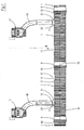
- the in Fig. 1 illustrated pipe kit consists of basically the same tubes 1, which are designed as composite corrugated pipes or double wall corrugated pipes. They consist of a smooth-walled, so substantially cylindrical inner tube 2 and a corrugated outer tube 3.
- the outer tube 3 has corrugations 4, each having a substantially annular cylindrical outer circumferential surface 5, lateral flanks 6, 7 and also again substantially annular cylindrical foot area 8 between the flanks 6, 7 of two adjacent corrugations 4 have.
- the outer tube 3 is welded to the inner tube 2 in each case.
- Inner tube 2 and outer tube 3 are made of plastics welded together.
- a sleeve 9 is formed, that is, an extended portion of the sleeve 9 facing away from the end of the mating of two adjacent tubes, so the so-called spigot 10, receives.
- the preparation of such tubes 1 with inline molded sleeve 9 is for example from the EP 0 563 575 A1 (corresponding U.S. Patent 5,320,797 ) known.
- the sleeve 9 can of course also be produced by subsequent expansion, by so-called Aufmuffen, a pipe produced without a sleeve.
- a muffle-free Pipe are used, wherein for joining two adjacent pipes, a double-plug-socket is used.
- the sleeves 9 and the spigots 10 form connection elements.
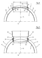
- Each tube 1 has between its two ends, ie between the sleeve 9 and the spigot end 10, one or more, in the present case two, flat, circular, flat connection surfaces 11. They each expediently have the same diameter d 11 . This is significantly smaller than the outer diameter d 3 of the outer tube 3. The following applies: d 11 ⁇ 0.5 d 3 .
- connection surfaces 11 are formed from the outer tube 3, d. H. Also below the connection surfaces 11, the inner tube 2 is formed as a substantially cylindrical tube. In the region of the wave troughs 12 located between two adjacent corrugations, the connection surface 11 therefore each has a lateral support wall 13. In the area of the central axis 15 of each connection surface 11 passing through the central longitudinal axis 14 of the tube 1, the connection surface 11 has only a very small distance to the inner tube 2. For the aforementioned reasons, the connection surface 11 is not or only slightly beyond the endeavorUmfangs vom 5 of the outer tube 3. It is connected in this area to the inner tube 2 by means of a hollow centering portion 16. The connection surfaces 11 of each tube 1 lie on a common surface line, d. H. its central axes 15 and the central longitudinal axis 14 lie in a common radial plane to the central longitudinal axis 14.
- a sewer pipe kit in Fig. 1 When attached to a, for example, as a sewer pipe kit in Fig. 1 only indicated road drains 17, ie sewage inlets, by means also designed as a composite pipes sewage supply pipes 18 are to be connected, then first by means of a crown drill a circular opening 19 in the connection surface 11 and then in the same operation a concentric opening 20 cut into the inner tube 2, such as Fig. 4, 5 and 8th is removable.
- the crown drill is centered in the centering section 16 of the connection surface 11.
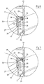
- connection piece 21 is used as a connection element in the openings 19, 20, which has a diameter of the openings 19, 20 adapted cylindrical connection portion 22, ie by the openings 19, 20 is inserted into the tube 1.
- the connection piece 21 further has a then located outside of the pipe 1 connection portion 23 which is formed in the manner of a sleeve and into which the waste water supply pipe 18 is inserted.
- locking webs 24 are integrally formed on the connection portion. These are formed on a ring land 25, which in turn projects radially from the outer wall 26 of the terminal portion 22 radially.
- the locking webs 24 extend parallel to the outer wall 26.
- At the lower free end of each locking web 24 is a to the connection portion 22, ie inwardly directed barb-shaped latch 27 is formed.
- inwardly directed latch receptacles 28 are formed, which are adapted to the locking webs 24 with latch 27.
- connection piece 21 is inserted into the openings 19, 20, then the locking webs 24 are bent by the emergence of the inclined casserole surfaces 29 of the bolt 27 on the support wall 13 radially to the axis 15 elastically until the connection piece 21 is inserted sufficiently far into the opening 19 of the connection surface 11. Then snap the latch 27 elastically into the bolt receptacles 28, as in the FIGS. 6 and 7 is shown.
- the elasticity of the locking webs 24 stems from the fact that the connecting piece 21 - are made of elastic, usually hard elastic plastic - as well as the tubes 1.
- the diameter d 19 of the opening 19 is smaller than the diameter d 11 of the connection surface 11, so that from the support wall 13, a ring edge 30 of the connection surface 11 projects inwardly, the inwardly the bolt Recordings 28 surpasses.
- a sealing ring 31 is placed, which in the embodiment of the FIGS. 4 to 6 and 8th has a U-shaped cross-section.
- the sealing ring 31 thus has - in cross-section - an upper sealing flange 32, a lower retaining flange 33 and these two flanges 32, 33 interconnecting seal web 34.
- the outer wall 26 of the terminal portion 22 has an outer diameter d 26 which is smaller than the diameter d 19 of the opening 19, but larger than the inner diameter d 34 of the sealing land 34 in the undeformed state.
- the connection section 22 has a tapered insertion section 35 at its lower free end.
- the snapping of the Latch 27 in the bolt receptacles 28 takes place under compression of the sealing flange 32 of the seal 31 between the annular web 25 and the annular connection surface 11.
- the main sealing function is thus between the edge 30 and the outer wall 26 of the connection portion 22nd given.
- the main sealing effect thus takes place through the sealing web 34 of the sealing ring 31 located between these two parts.
- the sealing flange 32 causes only an additional sealing.
- the diameter d 20 is smaller than the diameter d 19 .
- the diameter d 20 is equal to or slightly larger than the diameter d 26 of the connection portion 22, so that the latter is guided laterally in the opening 20 after insertion. This leads to a jamming of the connection nozzle 21 in the tube 1.
- the annular ridge 25 has the function of an axial stabilization of the connection nozzle 21 in the pipe first
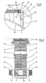
- the sealing ring 31 ' may also be formed in cross-section L-shaped and only have an upper sealing flange 32 and a sealing web 34.
- the sealing mechanism here is the same as previously described.
- the opening 19 can - as I said - intersect with a crown drill, so that the diameter d 19 of the opening and thus the edge 30 is very accurate.
- the connection piece 21 are produced by injection molding, so have very precise dimensions, ie very low manufacturing tolerances. The tightness of the described connection in the region of the sealing web 34 is therefore very high.
- the sealing ring 31 "as shown in FIG. 8 with sealing lips 36 having an inner diameter d 36 can be provided in the area of the sealing web 34 ", which abut against the outer wall 26 of the connection section 22 and thus contribute to a further increase in the sealing effect, so that also applies here: d 36 ⁇ d 26 .
- connection portion 22 The locking between the connecting piece 21 and pipe 1 can also be done by formed on the connection portion 22, outwardly projecting, barb-shaped latch which engage under the edge 30 of the connection surface 11, wherein it is expedient in such a case that the C- or U-shaped seal 31 or 31 "is used, in which case the bolt against the lower retaining flange 33 would abut.
- a revision shaft 37 which consists of serving as a shaft main body tube 1a and serving as an extension tube 1b. Both tubes 1a, 1b correspond in their construction of outer tube 3 with corrugation 4 and not shown inner tube to the tube 1.
- the upper tube 1b has a sleeve 9, by means of which the connection to the lower tube 1a is made.
- the upper tube 1b is closed with a lid 38.
- the lower tube 1a is closed at the bottom with a bottom 39.
- connecting surfaces 11 are formed in the manner described, in the manner also described connection spigot 21 are used in media-tight connection. Wastewater pipes 40 are connected to this connecting piece 21.
Landscapes
- Engineering & Computer Science (AREA)
- General Engineering & Computer Science (AREA)
- Mechanical Engineering (AREA)
- Branch Pipes, Bends, And The Like (AREA)
- Rigid Pipes And Flexible Pipes (AREA)
- Joints That Cut Off Fluids, And Hose Joints (AREA)
- Sewage (AREA)
- Non-Disconnectible Joints And Screw-Threaded Joints (AREA)
- Quick-Acting Or Multi-Walled Pipe Joints (AREA)
- Laying Of Electric Cables Or Lines Outside (AREA)
Priority Applications (1)
| Application Number | Priority Date | Filing Date | Title |
|---|---|---|---|
| PL05006194T PL1591712T3 (pl) | 2004-04-28 | 2005-03-22 | Zestaw elementów do łączenia rur i jego zastosowanie |
Applications Claiming Priority (2)
| Application Number | Priority Date | Filing Date | Title |
|---|---|---|---|
| DE102004020929 | 2004-04-28 | ||
| DE102004020929A DE102004020929A1 (de) | 2004-04-28 | 2004-04-28 | Bausatz für eine Rohr-Verbindung und dessen Verwendung |
Publications (3)
| Publication Number | Publication Date |
|---|---|
| EP1591712A2 EP1591712A2 (de) | 2005-11-02 |
| EP1591712A3 EP1591712A3 (de) | 2006-04-19 |
| EP1591712B1 true EP1591712B1 (de) | 2008-05-07 |
Family
ID=34934418
Family Applications (1)
| Application Number | Title | Priority Date | Filing Date |
|---|---|---|---|
| EP05006194A Expired - Lifetime EP1591712B1 (de) | 2004-04-28 | 2005-03-22 | Bausatz für eine Rohr-Verbindung und dessen Verwendung |
Country Status (4)
| Country | Link |
|---|---|
| EP (1) | EP1591712B1 (pl) |
| AT (1) | ATE394626T1 (pl) |
| DE (2) | DE102004020929A1 (pl) |
| PL (1) | PL1591712T3 (pl) |
Cited By (3)
| Publication number | Priority date | Publication date | Assignee | Title |
|---|---|---|---|---|
| EP2230359A2 (de) | 2009-03-16 | 2010-09-22 | Ralph Peter Hegler | Bausatz für eine Verbindung eines Inspektions-Schachtes mit einer Abfluss-Leitung |
| DE102009037042A1 (de) | 2009-08-13 | 2011-02-17 | Hegler Plastik Gmbh | Schacht, insbesondere Kontroll- und Spül-Schacht für Abwasser mit einem Fließ-Gerinne und Platte für ein Fließ-Gerinne |
| EP3620704B1 (de) | 2018-09-04 | 2023-08-16 | Voss Automotive GmbH | Verfahren zum herstellen eines insbesondere flexiblen verteilerrohres |
Families Citing this family (1)
| Publication number | Priority date | Publication date | Assignee | Title |
|---|---|---|---|---|
| US12523326B2 (en) * | 2022-09-14 | 2026-01-13 | Press-Seal Corporation | Lateral connector for underground pipes |
Family Cites Families (13)
| Publication number | Priority date | Publication date | Assignee | Title |
|---|---|---|---|---|
| DE7145610U (de) * | Alrop Finanz Anstalt | Anschlußstutzen für Sammelrohre aus Kunststoff bei Grundwasserabsenkungsanlagen | ||
| NL8202299A (nl) * | 1982-06-07 | 1984-01-02 | Wavin Bv | Kunststofput. |
| US4772389A (en) * | 1987-07-21 | 1988-09-20 | Denis Guibault | Pipe and its retainer in a tank |
| GB8810043D0 (en) * | 1988-04-28 | 1988-06-02 | Barrow V | Catch pit |
| JPH03107696A (ja) * | 1989-09-21 | 1991-05-08 | Sekisui Chem Co Ltd | 分岐接続管継手およびその接続方法 |
| DE4210482A1 (de) * | 1992-03-31 | 1993-10-07 | Wilhelm Hegler | Verfahren und Vorrichtung zur fortlaufenden Herstellung eines Verbundrohres mit Rohr-Muffe |
| DE9407435U1 (de) * | 1994-04-29 | 1994-09-22 | Nyloplast Europe B.V., 's-Gravendeel | Rohrverbindungssystem |
| DE29708509U1 (de) * | 1997-05-14 | 1997-07-10 | Steinzeug GmbH, 50858 Köln | Anschlußstück zum Anschließen eines Abzweigrohres an ein verlegtes Kanalisationsrohr |
| US5957505A (en) * | 1997-10-17 | 1999-09-28 | Uponor Innovation Ab | Branch pipe connection |
| DE19747863A1 (de) * | 1997-10-30 | 1999-05-06 | Ralph Peter Dr Ing Hegler | Spül- und Kontroll-Schacht für Flüssigkeitsleitungen und Schacht-Abschnitt hierfür |
| DE19927591B4 (de) * | 1998-12-12 | 2008-02-28 | Funke Kunststoffe Gmbh | Vorrichtung zum dichtschließenden Verbinden eines Kanalrohres mit einem Anschlußrohr |
| DE10155683A1 (de) * | 2001-11-13 | 2003-05-15 | Drossbach Gmbh & Co Kg | Dränschacht und Verfahren zu seiner Herstellung |
| DE20204227U1 (de) * | 2002-03-16 | 2002-05-29 | Funke Kunststoffe GmbH, 48324 Sendenhorst | Verschraubbarer Abzweig für Wellrohre |
-
2004
- 2004-04-28 DE DE102004020929A patent/DE102004020929A1/de not_active Withdrawn
-
2005
- 2005-03-22 EP EP05006194A patent/EP1591712B1/de not_active Expired - Lifetime
- 2005-03-22 AT AT05006194T patent/ATE394626T1/de not_active IP Right Cessation
- 2005-03-22 PL PL05006194T patent/PL1591712T3/pl unknown
- 2005-03-22 DE DE502005003944T patent/DE502005003944D1/de not_active Expired - Lifetime
Cited By (6)
| Publication number | Priority date | Publication date | Assignee | Title |
|---|---|---|---|---|
| EP2230359A2 (de) | 2009-03-16 | 2010-09-22 | Ralph Peter Hegler | Bausatz für eine Verbindung eines Inspektions-Schachtes mit einer Abfluss-Leitung |
| DE102009013066A1 (de) | 2009-03-16 | 2010-09-23 | Hegler, Ralph Peter, Dr.-Ing. | Bausatz für eine Verbindung eines Inspektions-Schachtes mit einer Abfluss-Leitung |
| DE102009037042A1 (de) | 2009-08-13 | 2011-02-17 | Hegler Plastik Gmbh | Schacht, insbesondere Kontroll- und Spül-Schacht für Abwasser mit einem Fließ-Gerinne und Platte für ein Fließ-Gerinne |
| EP2295655A2 (de) | 2009-08-13 | 2011-03-16 | Hegler Plastik GmbH | Schacht, insbesondere Kontroll- und Spül-Schacht für Abwasser mit einem Fließ-Gerinne und Platte für ein Fließ-Gerinne |
| EP2295655A3 (de) * | 2009-08-13 | 2014-08-06 | Hegler Plastik GmbH | Schacht, insbesondere Kontroll- und Spül-Schacht für Abwasser mit einem Fließ-Gerinne und Platte für ein Fließ-Gerinne |
| EP3620704B1 (de) | 2018-09-04 | 2023-08-16 | Voss Automotive GmbH | Verfahren zum herstellen eines insbesondere flexiblen verteilerrohres |
Also Published As
| Publication number | Publication date |
|---|---|
| PL1591712T3 (pl) | 2008-10-31 |
| DE502005003944D1 (de) | 2008-06-19 |
| EP1591712A3 (de) | 2006-04-19 |
| EP1591712A2 (de) | 2005-11-02 |
| ATE394626T1 (de) | 2008-05-15 |
| DE102004020929A1 (de) | 2005-11-24 |
Similar Documents
| Publication | Publication Date | Title |
|---|---|---|
| EP0913534B1 (de) | Spül- und Kontroll-Schacht für Flüssigkeitsleitungen und Schacht-Abschnitt hierfür | |
| EP2230359A2 (de) | Bausatz für eine Verbindung eines Inspektions-Schachtes mit einer Abfluss-Leitung | |
| EP0975914B1 (de) | Verschraubbarer abzweig für dünnwandige kanalrohre | |
| DE202006012625U1 (de) | Entwässerungsvorrichtung | |
| EP1591712B1 (de) | Bausatz für eine Rohr-Verbindung und dessen Verwendung | |
| DE202015106969U1 (de) | Anschlusssystem | |
| CH669828A5 (pl) | ||
| DE2427637A1 (de) | Anschlussmuffe | |
| DE10034676A1 (de) | Anordnung mit einer Anschlußmuffe und Anschlußmuffe sowie Sohlschale, Öffnungsausbildung und Formkern | |
| EP1751460B1 (de) | Anschlusseinrichtung | |
| DE202015106967U1 (de) | Anschlusssystem | |
| DE4212278C2 (de) | Übergangsverbinder für eine Rohrleitung | |
| DE202012010724U1 (de) | Tiefbaurohrsystem mit wenigstens einem Betonhohlkörper sowie Abschlusselement hierfür | |
| EP1775507A1 (de) | Fitting für Rohrleitungen | |
| DE2550202A1 (de) | Rohrflansch | |
| DE202009014250U1 (de) | Steckkupplung zum Verbinden von insbesondere Kunststoff-Rohren | |
| DE19816855C2 (de) | Anschlußstück zum Anschließen eines Abzweigrohres an ein verlegtes Kanalisationsrohr | |
| DE3941884C2 (de) | Rohrverbindung für Entwässerungskanäle beim Vortrieb mit Betonrohren | |
| DE10152596A1 (de) | Verfahren und Vorrichtung zum Anschließen einer wasserdichten Kunststoffschicht | |
| DE102020134023B4 (de) | Manschettenanschlussvorrichtung, Herstellungsverfahren und Verfahren zur Einbindung oder Sanierung von Anschlüssen | |
| DE60309311T2 (de) | Rohrabzweigung mit buchse mit einer keilförmigen nut und keil zum einführen in die buchse | |
| CH686798A5 (de) | Steckmuffe. | |
| EP1344970B1 (de) | Ringdichtungselement | |
| DE202006001226U1 (de) | Anschlussstutzen für einen Abwasser-Hauptkanal | |
| AT502404A4 (de) | Kupplung für ein wellrohr |
Legal Events
| Date | Code | Title | Description |
|---|---|---|---|
| PUAI | Public reference made under article 153(3) epc to a published international application that has entered the european phase |
Free format text: ORIGINAL CODE: 0009012 |
|
| AK | Designated contracting states |
Kind code of ref document: A2 Designated state(s): AT BE BG CH CY CZ DE DK EE ES FI FR GB GR HU IE IS IT LI LT LU MC NL PL PT RO SE SI SK TR |
|
| AX | Request for extension of the european patent |
Extension state: AL BA HR LV MK YU |
|
| PUAL | Search report despatched |
Free format text: ORIGINAL CODE: 0009013 |
|
| AK | Designated contracting states |
Kind code of ref document: A3 Designated state(s): AT BE BG CH CY CZ DE DK EE ES FI FR GB GR HU IE IS IT LI LT LU MC NL PL PT RO SE SI SK TR |
|
| AX | Request for extension of the european patent |
Extension state: AL BA HR LV MK YU |
|
| RIC1 | Information provided on ipc code assigned before grant |
Ipc: F16L 41/02 20060101ALI20060227BHEP Ipc: F16L 41/08 20060101AFI20050728BHEP Ipc: F16L 25/00 20060101ALI20060227BHEP |
|
| 17P | Request for examination filed |
Effective date: 20060921 |
|
| AKX | Designation fees paid |
Designated state(s): AT BE BG CH CY CZ DE DK EE ES FI FR GB GR HU IE IS IT LI LT LU MC NL PL PT RO SE SI SK TR |
|
| GRAP | Despatch of communication of intention to grant a patent |
Free format text: ORIGINAL CODE: EPIDOSNIGR1 |
|
| GRAS | Grant fee paid |
Free format text: ORIGINAL CODE: EPIDOSNIGR3 |
|
| GRAA | (expected) grant |
Free format text: ORIGINAL CODE: 0009210 |
|
| AK | Designated contracting states |
Kind code of ref document: B1 Designated state(s): AT BE BG CH CY CZ DE DK EE ES FI FR GB GR HU IE IS IT LI LT LU MC NL PL PT RO SE SI SK TR |
|
| REG | Reference to a national code |
Ref country code: GB Ref legal event code: FG4D Free format text: NOT ENGLISH |
|
| REG | Reference to a national code |
Ref country code: CH Ref legal event code: EP |
|
| REG | Reference to a national code |
Ref country code: IE Ref legal event code: FG4D Free format text: LANGUAGE OF EP DOCUMENT: GERMAN |
|
| REF | Corresponds to: |
Ref document number: 502005003944 Country of ref document: DE Date of ref document: 20080619 Kind code of ref document: P |
|
| PG25 | Lapsed in a contracting state [announced via postgrant information from national office to epo] |
Ref country code: SI Free format text: LAPSE BECAUSE OF FAILURE TO SUBMIT A TRANSLATION OF THE DESCRIPTION OR TO PAY THE FEE WITHIN THE PRESCRIBED TIME-LIMIT Effective date: 20080507 |
|
| PG25 | Lapsed in a contracting state [announced via postgrant information from national office to epo] |
Ref country code: ES Free format text: LAPSE BECAUSE OF FAILURE TO SUBMIT A TRANSLATION OF THE DESCRIPTION OR TO PAY THE FEE WITHIN THE PRESCRIBED TIME-LIMIT Effective date: 20080818 Ref country code: NL Free format text: LAPSE BECAUSE OF FAILURE TO SUBMIT A TRANSLATION OF THE DESCRIPTION OR TO PAY THE FEE WITHIN THE PRESCRIBED TIME-LIMIT Effective date: 20080507 Ref country code: FI Free format text: LAPSE BECAUSE OF FAILURE TO SUBMIT A TRANSLATION OF THE DESCRIPTION OR TO PAY THE FEE WITHIN THE PRESCRIBED TIME-LIMIT Effective date: 20080507 |
|
| REG | Reference to a national code |
Ref country code: PL Ref legal event code: T3 |
|
| NLV1 | Nl: lapsed or annulled due to failure to fulfill the requirements of art. 29p and 29m of the patents act | ||
| REG | Reference to a national code |
Ref country code: IE Ref legal event code: FD4D |
|
| PG25 | Lapsed in a contracting state [announced via postgrant information from national office to epo] |
Ref country code: IS Free format text: LAPSE BECAUSE OF FAILURE TO SUBMIT A TRANSLATION OF THE DESCRIPTION OR TO PAY THE FEE WITHIN THE PRESCRIBED TIME-LIMIT Effective date: 20080907 |
|
| PG25 | Lapsed in a contracting state [announced via postgrant information from national office to epo] |
Ref country code: DK Free format text: LAPSE BECAUSE OF FAILURE TO SUBMIT A TRANSLATION OF THE DESCRIPTION OR TO PAY THE FEE WITHIN THE PRESCRIBED TIME-LIMIT Effective date: 20080507 Ref country code: IE Free format text: LAPSE BECAUSE OF FAILURE TO SUBMIT A TRANSLATION OF THE DESCRIPTION OR TO PAY THE FEE WITHIN THE PRESCRIBED TIME-LIMIT Effective date: 20080507 Ref country code: LT Free format text: LAPSE BECAUSE OF FAILURE TO SUBMIT A TRANSLATION OF THE DESCRIPTION OR TO PAY THE FEE WITHIN THE PRESCRIBED TIME-LIMIT Effective date: 20080507 Ref country code: SE Free format text: LAPSE BECAUSE OF FAILURE TO SUBMIT A TRANSLATION OF THE DESCRIPTION OR TO PAY THE FEE WITHIN THE PRESCRIBED TIME-LIMIT Effective date: 20080807 Ref country code: PT Free format text: LAPSE BECAUSE OF FAILURE TO SUBMIT A TRANSLATION OF THE DESCRIPTION OR TO PAY THE FEE WITHIN THE PRESCRIBED TIME-LIMIT Effective date: 20081007 |
|
| PG25 | Lapsed in a contracting state [announced via postgrant information from national office to epo] |
Ref country code: SK Free format text: LAPSE BECAUSE OF FAILURE TO SUBMIT A TRANSLATION OF THE DESCRIPTION OR TO PAY THE FEE WITHIN THE PRESCRIBED TIME-LIMIT Effective date: 20080507 Ref country code: RO Free format text: LAPSE BECAUSE OF FAILURE TO SUBMIT A TRANSLATION OF THE DESCRIPTION OR TO PAY THE FEE WITHIN THE PRESCRIBED TIME-LIMIT Effective date: 20080507 |
|
| PLBE | No opposition filed within time limit |
Free format text: ORIGINAL CODE: 0009261 |
|
| STAA | Information on the status of an ep patent application or granted ep patent |
Free format text: STATUS: NO OPPOSITION FILED WITHIN TIME LIMIT |
|
| 26N | No opposition filed |
Effective date: 20090210 |
|
| PG25 | Lapsed in a contracting state [announced via postgrant information from national office to epo] |
Ref country code: BG Free format text: LAPSE BECAUSE OF FAILURE TO SUBMIT A TRANSLATION OF THE DESCRIPTION OR TO PAY THE FEE WITHIN THE PRESCRIBED TIME-LIMIT Effective date: 20080807 Ref country code: EE Free format text: LAPSE BECAUSE OF FAILURE TO SUBMIT A TRANSLATION OF THE DESCRIPTION OR TO PAY THE FEE WITHIN THE PRESCRIBED TIME-LIMIT Effective date: 20080507 |
|
| PG25 | Lapsed in a contracting state [announced via postgrant information from national office to epo] |
Ref country code: IT Free format text: LAPSE BECAUSE OF FAILURE TO SUBMIT A TRANSLATION OF THE DESCRIPTION OR TO PAY THE FEE WITHIN THE PRESCRIBED TIME-LIMIT Effective date: 20080507 |
|
| BERE | Be: lapsed |
Owner name: HEGLER, RALPH-PETER, DR.-ING. Effective date: 20090331 |
|
| PG25 | Lapsed in a contracting state [announced via postgrant information from national office to epo] |
Ref country code: MC Free format text: LAPSE BECAUSE OF NON-PAYMENT OF DUE FEES Effective date: 20090331 |
|
| REG | Reference to a national code |
Ref country code: CH Ref legal event code: PL |
|
| PG25 | Lapsed in a contracting state [announced via postgrant information from national office to epo] |
Ref country code: CH Free format text: LAPSE BECAUSE OF NON-PAYMENT OF DUE FEES Effective date: 20090331 Ref country code: LI Free format text: LAPSE BECAUSE OF NON-PAYMENT OF DUE FEES Effective date: 20090331 |
|
| PG25 | Lapsed in a contracting state [announced via postgrant information from national office to epo] |
Ref country code: BE Free format text: LAPSE BECAUSE OF NON-PAYMENT OF DUE FEES Effective date: 20090331 |
|
| PG25 | Lapsed in a contracting state [announced via postgrant information from national office to epo] |
Ref country code: AT Free format text: LAPSE BECAUSE OF NON-PAYMENT OF DUE FEES Effective date: 20090322 |
|
| PGFP | Annual fee paid to national office [announced via postgrant information from national office to epo] |
Ref country code: GB Payment date: 20100324 Year of fee payment: 6 |
|
| PG25 | Lapsed in a contracting state [announced via postgrant information from national office to epo] |
Ref country code: GR Free format text: LAPSE BECAUSE OF FAILURE TO SUBMIT A TRANSLATION OF THE DESCRIPTION OR TO PAY THE FEE WITHIN THE PRESCRIBED TIME-LIMIT Effective date: 20080808 |
|
| PG25 | Lapsed in a contracting state [announced via postgrant information from national office to epo] |
Ref country code: LU Free format text: LAPSE BECAUSE OF NON-PAYMENT OF DUE FEES Effective date: 20090322 |
|
| PG25 | Lapsed in a contracting state [announced via postgrant information from national office to epo] |
Ref country code: HU Free format text: LAPSE BECAUSE OF FAILURE TO SUBMIT A TRANSLATION OF THE DESCRIPTION OR TO PAY THE FEE WITHIN THE PRESCRIBED TIME-LIMIT Effective date: 20081108 |
|
| PG25 | Lapsed in a contracting state [announced via postgrant information from national office to epo] |
Ref country code: TR Free format text: LAPSE BECAUSE OF FAILURE TO SUBMIT A TRANSLATION OF THE DESCRIPTION OR TO PAY THE FEE WITHIN THE PRESCRIBED TIME-LIMIT Effective date: 20080507 |
|
| PG25 | Lapsed in a contracting state [announced via postgrant information from national office to epo] |
Ref country code: CY Free format text: LAPSE BECAUSE OF FAILURE TO SUBMIT A TRANSLATION OF THE DESCRIPTION OR TO PAY THE FEE WITHIN THE PRESCRIBED TIME-LIMIT Effective date: 20080507 |
|
| GBPC | Gb: european patent ceased through non-payment of renewal fee |
Effective date: 20110322 |
|
| PG25 | Lapsed in a contracting state [announced via postgrant information from national office to epo] |
Ref country code: GB Free format text: LAPSE BECAUSE OF NON-PAYMENT OF DUE FEES Effective date: 20110322 |
|
| PGFP | Annual fee paid to national office [announced via postgrant information from national office to epo] |
Ref country code: CZ Payment date: 20130313 Year of fee payment: 9 Ref country code: FR Payment date: 20130329 Year of fee payment: 9 |
|
| PGFP | Annual fee paid to national office [announced via postgrant information from national office to epo] |
Ref country code: PL Payment date: 20130220 Year of fee payment: 9 |
|
| PG25 | Lapsed in a contracting state [announced via postgrant information from national office to epo] |
Ref country code: CZ Free format text: LAPSE BECAUSE OF NON-PAYMENT OF DUE FEES Effective date: 20140322 |
|
| REG | Reference to a national code |
Ref country code: FR Ref legal event code: ST Effective date: 20141128 |
|
| PG25 | Lapsed in a contracting state [announced via postgrant information from national office to epo] |
Ref country code: FR Free format text: LAPSE BECAUSE OF NON-PAYMENT OF DUE FEES Effective date: 20140331 |
|
| PG25 | Lapsed in a contracting state [announced via postgrant information from national office to epo] |
Ref country code: PL Free format text: LAPSE BECAUSE OF NON-PAYMENT OF DUE FEES Effective date: 20140322 |
|
| REG | Reference to a national code |
Ref country code: PL Ref legal event code: LAPE |
|
| PGFP | Annual fee paid to national office [announced via postgrant information from national office to epo] |
Ref country code: DE Payment date: 20150525 Year of fee payment: 11 |
|
| REG | Reference to a national code |
Ref country code: DE Ref legal event code: R119 Ref document number: 502005003944 Country of ref document: DE |
|
| PG25 | Lapsed in a contracting state [announced via postgrant information from national office to epo] |
Ref country code: DE Free format text: LAPSE BECAUSE OF NON-PAYMENT OF DUE FEES Effective date: 20161001 |