EP1590273B1 - Palette für eine förderkette - Google Patents
Palette für eine förderkette Download PDFInfo
- Publication number
- EP1590273B1 EP1590273B1 EP03813168A EP03813168A EP1590273B1 EP 1590273 B1 EP1590273 B1 EP 1590273B1 EP 03813168 A EP03813168 A EP 03813168A EP 03813168 A EP03813168 A EP 03813168A EP 1590273 B1 EP1590273 B1 EP 1590273B1
- Authority
- EP
- European Patent Office
- Prior art keywords
- chain
- plate
- pallet
- conveyor
- pallets
- Prior art date
- Legal status (The legal status is an assumption and is not a legal conclusion. Google has not performed a legal analysis and makes no representation as to the accuracy of the status listed.)
- Expired - Lifetime
Links
- 238000006073 displacement reaction Methods 0.000 abstract 1
- 206010064031 Limb crushing injury Diseases 0.000 description 1
- 230000003100 immobilizing effect Effects 0.000 description 1
- 230000001939 inductive effect Effects 0.000 description 1
- 238000009434 installation Methods 0.000 description 1
- 238000004519 manufacturing process Methods 0.000 description 1
- 238000010008 shearing Methods 0.000 description 1
- 229920002994 synthetic fiber Polymers 0.000 description 1
Images


Classifications
-
- B—PERFORMING OPERATIONS; TRANSPORTING
- B65—CONVEYING; PACKING; STORING; HANDLING THIN OR FILAMENTARY MATERIAL
- B65G—TRANSPORT OR STORAGE DEVICES, e.g. CONVEYORS FOR LOADING OR TIPPING, SHOP CONVEYOR SYSTEMS OR PNEUMATIC TUBE CONVEYORS
- B65G17/00—Conveyors having an endless traction element, e.g. a chain, transmitting movement to a continuous or substantially-continuous load-carrying surface or to a series of individual load-carriers; Endless-chain conveyors in which the chains form the load-carrying surface
- B65G17/16—Conveyors having an endless traction element, e.g. a chain, transmitting movement to a continuous or substantially-continuous load-carrying surface or to a series of individual load-carriers; Endless-chain conveyors in which the chains form the load-carrying surface comprising individual load-carriers which are pivotally mounted, e.g. for free-swinging movement
- B65G17/18—Conveyors having an endless traction element, e.g. a chain, transmitting movement to a continuous or substantially-continuous load-carrying surface or to a series of individual load-carriers; Endless-chain conveyors in which the chains form the load-carrying surface comprising individual load-carriers which are pivotally mounted, e.g. for free-swinging movement and move in contact with a guiding surface
-
- B—PERFORMING OPERATIONS; TRANSPORTING
- B65—CONVEYING; PACKING; STORING; HANDLING THIN OR FILAMENTARY MATERIAL
- B65G—TRANSPORT OR STORAGE DEVICES, e.g. CONVEYORS FOR LOADING OR TIPPING, SHOP CONVEYOR SYSTEMS OR PNEUMATIC TUBE CONVEYORS
- B65G17/00—Conveyors having an endless traction element, e.g. a chain, transmitting movement to a continuous or substantially-continuous load-carrying surface or to a series of individual load-carriers; Endless-chain conveyors in which the chains form the load-carrying surface
- B65G17/06—Conveyors having an endless traction element, e.g. a chain, transmitting movement to a continuous or substantially-continuous load-carrying surface or to a series of individual load-carriers; Endless-chain conveyors in which the chains form the load-carrying surface having a load-carrying surface formed by a series of interconnected, e.g. longitudinal, links, plates, or platforms
- B65G17/065—Conveyors having an endless traction element, e.g. a chain, transmitting movement to a continuous or substantially-continuous load-carrying surface or to a series of individual load-carriers; Endless-chain conveyors in which the chains form the load-carrying surface having a load-carrying surface formed by a series of interconnected, e.g. longitudinal, links, plates, or platforms the load carrying surface being formed by plates or platforms attached to a single traction element
- B65G17/066—Conveyors having an endless traction element, e.g. a chain, transmitting movement to a continuous or substantially-continuous load-carrying surface or to a series of individual load-carriers; Endless-chain conveyors in which the chains form the load-carrying surface having a load-carrying surface formed by a series of interconnected, e.g. longitudinal, links, plates, or platforms the load carrying surface being formed by plates or platforms attached to a single traction element specially adapted to follow a curved path
-
- B—PERFORMING OPERATIONS; TRANSPORTING
- B65—CONVEYING; PACKING; STORING; HANDLING THIN OR FILAMENTARY MATERIAL
- B65G—TRANSPORT OR STORAGE DEVICES, e.g. CONVEYORS FOR LOADING OR TIPPING, SHOP CONVEYOR SYSTEMS OR PNEUMATIC TUBE CONVEYORS
- B65G17/00—Conveyors having an endless traction element, e.g. a chain, transmitting movement to a continuous or substantially-continuous load-carrying surface or to a series of individual load-carriers; Endless-chain conveyors in which the chains form the load-carrying surface
- B65G17/30—Details; Auxiliary devices
- B65G17/32—Individual load-carriers
- B65G17/34—Individual load-carriers having flat surfaces, e.g. platforms, grids, forks
-
- B—PERFORMING OPERATIONS; TRANSPORTING
- B65—CONVEYING; PACKING; STORING; HANDLING THIN OR FILAMENTARY MATERIAL
- B65G—TRANSPORT OR STORAGE DEVICES, e.g. CONVEYORS FOR LOADING OR TIPPING, SHOP CONVEYOR SYSTEMS OR PNEUMATIC TUBE CONVEYORS
- B65G17/00—Conveyors having an endless traction element, e.g. a chain, transmitting movement to a continuous or substantially-continuous load-carrying surface or to a series of individual load-carriers; Endless-chain conveyors in which the chains form the load-carrying surface
- B65G17/30—Details; Auxiliary devices
- B65G17/38—Chains or like traction elements; Connections between traction elements and load-carriers
- B65G17/42—Attaching load carriers to traction elements
Definitions
- the present invention relates to a pallet for a conveyor chain according to the preamble of claim 1, a pallet chain according to the preamble of claim 2 and a chain conveyor according to the preamble of claim 8.
- Pallets are fixed by any means, including integral, to chain links, usually bush links, roller or cardan.
- the axes of the bushings or rollers are arranged substantially vertically in the conveyor and the pallets are fixed to the linkage axes between links, so as to be horizontal.
- the bush chains have a good tensile strength which makes it possible to realize sinuous trajectories of great length. They also allow a drive from the side, particularly economical.
- Chain guidance is achieved by the links sliding in a profile or profile assembly.
- the curves of the trajectory are made possible by the shape of the pallets which allows them to orient themselves relative to each other in their plane.
- the vanes move between the guiding walls that protrude above their upper surface to guide the transported objects.
- this conveyor requires the use of two different types of pallets and their precise relative positioning, which is expensive in terms of manufacture and assembly.
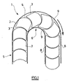
- Figure 1 shows another vane chain 1 of the prior art. This figure illustrates the fact that the maximization of the usable surface is generally obtained with pallets 2 whose front edge 3 and the rear edge 4 are substantially circular with the same radius, one of these edges being convex and the other concave. Various forms of pallets have already been made on this principle.
- edges 3 and 4 fit one into the other so that in both the straight portions such as in the curves such as 6, almost the entire area between the guide walls 7 is covered. by the pallets.
- the pallets depart and leave each other, in particular their lateral edges 7, and the guide walls 8 of the interstices 9.
- an object can be introduced inadvertently, or worse, the finger of an operator.
- the gap closes and may sever the trapped finger.
- the document DE 299 22 101 U also describes a conveyor in which the bearing surface has been increased, via the use of crescent-shaped pallets, the concave face of a pallet cooperating with the convex face of an adjacent pallet.
- US 2 181 659 A1 discloses a conveyor comprising disk-shaped pallets. The pallets overlap each other.
- the overlap of the pallets has the disadvantage of inducing a shearing movement as the pallet chain moves from a straight path to a curved path.
- this overlap uses the pallets.
- An object of the invention is to provide a pallet conveyor which eliminates the risk of jamming an object, and more particularly that does not present a danger to an operator.
- the invention avoids the risk of jamming, especially by providing that the surfaces defined above are not narrowed during the passage of a curved portion to a straight portion or vice versa.
- the links may be bushing links.
- At least one pallet is rotatable about an axis orthogonal to the plane of the pallets, with respect to the link of the chain carrying said pallet.
- At least one pallet is immobilized relative to the link of the chain carrying said pallet.
- each pallet may be carried by two adjacent bushing pins or, alternatively, carried by a single bushing axis, locking means of the rotation of the pallet about said axis being then provided.
- each pallet may be carried by two adjacent socket pins.
- the subject of the invention is a chain conveyor according to claim 8.
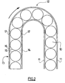
- the conveyor comprises a succession of pallets 10 of substantially identical shapes.
- the pallets 10 have a shape, circular in this way, that both in the curves of maximum radius 12 and in the straight portions 13, the space 14 delimited by the rear edge 15 of a pallet, the front edge 16 of the pallet which follows, the side edges 17 of these pallets and one of the guide walls 11, has a sufficient surface so that a finger of a user can not be pinched.
- the diameter of the pallets 10 is slightly smaller than the distance between the guide walls 11.
- the distance between the centers of two adjacent pallets 10 is slightly greater than the diameter of the pallets so that the front edge 15 of a pallet is the closest possible the rear edge 16 of the pallet that precedes and the driving surface of the conveyor is maximum.
- the pallets 10 are close to each other, but are spaced apart and do not overlap, which notably avoids the risk of wear. In addition, it is not provided between two successive pallets 10 of intermediate element that can cause jamming problems.
- each guide wall 11 is formed of one of the wings of an angle member 18.
- the other wing 19 of each angle 18 is attached to a support profile 20 with bolts 21 cooperating with nuts (not shown) engaged and held in upper grooves 22 of the support profile 20.
- the support profile 20 also includes two pairs of lateral grooves 23 for attaching accessories such as sensors or actuators, and two lower mounting grooves 24 for attaching the profile to any suitable installation support.
- the support profile 20 also forms two substantially horizontal support ribs 25 in the installed operating position, which extend from the outside of the profile towards its vertical plane of symmetry.
- the inner edges of the support ribs 25 define a longitudinal slot 26 and form a clipping profile 27.
- the support profile 20 finally forms a connecting profile 28 connecting transversely the two support ribs 25 below the longitudinal slot 26.
- the two support ribs 25 and the connecting profile 28 thus form a longitudinal box 29 open towards the high along the slit 26.
- Each sliding profile 30 covers the upper surface of one of the support ribs 25 and the corresponding edge of the longitudinal slot 26.
- the conveyor chain 31 is a known type bushing chain whose links 32 are connected by rivets 33 on which the bushes 34 are engaged.
- Each pallet 10 is mounted on the chain by means of two successive rivets 33.
- four successive rivets separate each group of two rivets carrying a pallet 10.
- Each pallet 10 is thus immobilized with respect to the chain and in particular can not pivot about its axis.
- This configuration is advantageous, in particular because it makes it possible to limit the wear of the pallets by the objects transported.
- the pallet 10 can be carried by a single bushing axis, locking means of the rotation of the pallet 10 about its axis being provided.
- the chain 31 is arranged on the support profile 20 so that the face of the pallets 10 located on the side of the chain rests on the sliding profiles 30, the chain extending in the box 28 through the slot 26 which ensures its guidance.
- Lateral drive means of any known type can drive the chain 31.
- the chain is guided by the pallets 10 which are themselves guided by the guide walls 11 of the brackets 18.
- the invention thus provides a chain conveyor having good mechanical qualities and furthermore not presenting any danger for its operators.
Landscapes
- Engineering & Computer Science (AREA)
- Mechanical Engineering (AREA)
- Chain Conveyers (AREA)
- Devices For Conveying Motion By Means Of Endless Flexible Members (AREA)
- Attitude Control For Articles On Conveyors (AREA)
Claims (10)
- Palette für Förderbandkette, die so gestaltet ist, daß sie auf eine Antriebskette (31) montiert werden kann, die fähig ist, eine Aufeinanderfolge von Paletten (10) deutlich in einer Ebene und in einer Antriebsrichtung eine Bahn entlang zu transportieren, die gerade Abschnitte (13) und Abschnitte mit maximaler Biegung (12) umfaßt, dadurch gekennzeichnet, daß die Kanten der Paletten deutlich kreisförmig und von gleicher Abmessung sind, wobei der Anstand zwischen den Mittelpunkten zweier anschließender Paletten (10) leicht größer als der Durchmesser der Paletten ist.
- Förderbandkette, die eine Aufeinanderfolge von Kettengliedern (31) umfaßt, wobei mindestens manche der Kettenglieder eine Palette (10) tragen, dadurch gekennzeichnet, daß die besagte Palette dem Patentanspruch 1 entspricht.
- Kette nach Anspruch 2, bei der die Kettenglieder solche mit Hülsen sind.
- Kette nach einem beliebigen der vorstehenden Ansprüche 2 bis 3, bei der mindestens eine Palette in Drehung um eine orthogonal zur Ebene der Paletten stehende Achse gegenüber dem Kettenglied (31) der Kette beweglich ist, die die besagte Palette trägt.
- Kette nach einem beliebigen der vorstehenden Ansprüche 2 bis 3, bei der mindestens eine Palette gegenüber dem Kettenglied (31) der Kette gesperrt ist, die die besagte Palette trägt.
- Kette nach den Ansprüchen 3 und 5, bei der jede Palette von zwei anschließenden Hülsenachsen (33) getragen werden.
- Kette nach den Ansprüchen 3 und 5, bei der jede Palette von einer einzigen Hülsenachse (33) getragen wird, wobei Mittel zur Blockierung der Drehung der Palette um die besagte Achse (33) vorgesehen sind.
- Förderbandkette, die eine Kette (31) mit Paletten und einen Träger (18, 20) mit Führungswänden (11) umfaßt, dadurch gekennzeichnet, daß die besagte Kette dem Anspruch 2 entspricht.
- Förderband nach Anspruch 8, bei dem die Kettenglieder der Kette Kettenglieder mit Hülsen (34) sind.
- Förderband nach Anspruch 9, bei dem jede Palette (10) von zwei anschließenden Hülsenachsen (33) getragen werden.
Applications Claiming Priority (3)
| Application Number | Priority Date | Filing Date | Title |
|---|---|---|---|
| FR0215650A FR2848539B1 (fr) | 2002-12-11 | 2002-12-11 | Palette pour chaine de convoyeur |
| FR0215650 | 2002-12-11 | ||
| PCT/FR2003/003679 WO2004054902A1 (fr) | 2002-12-11 | 2003-12-11 | Palette pour chaîne de convoyeur__________________________ |
Publications (3)
| Publication Number | Publication Date |
|---|---|
| EP1590273A1 EP1590273A1 (de) | 2005-11-02 |
| EP1590273B1 true EP1590273B1 (de) | 2007-03-28 |
| EP1590273B8 EP1590273B8 (de) | 2007-08-08 |
Family
ID=32338677
Family Applications (1)
| Application Number | Title | Priority Date | Filing Date |
|---|---|---|---|
| EP03813168A Expired - Lifetime EP1590273B8 (de) | 2002-12-11 | 2003-12-11 | Palette für eine förderkette |
Country Status (7)
| Country | Link |
|---|---|
| US (1) | US20060151300A1 (de) |
| EP (1) | EP1590273B8 (de) |
| AT (1) | ATE358082T1 (de) |
| AU (1) | AU2003296821A1 (de) |
| DE (1) | DE60312896D1 (de) |
| FR (1) | FR2848539B1 (de) |
| WO (1) | WO2004054902A1 (de) |
Families Citing this family (6)
| Publication number | Priority date | Publication date | Assignee | Title |
|---|---|---|---|---|
| US7355975B2 (en) * | 2004-04-30 | 2008-04-08 | International Business Machines Corporation | Method and apparatus for group communication with end-to-end reliability |
| CH704134A1 (de) | 2010-11-26 | 2012-05-31 | Ferag Ag | Fördersystem, förderelement und führungskanal. |
| JP2014193761A (ja) * | 2013-03-29 | 2014-10-09 | Toyota Industries Corp | 搬送装置 |
| ITUB20152972A1 (it) * | 2015-08-06 | 2015-11-06 | System Plast S R L | Supporto curvilineo per convogliatori a catena |
| US10085676B1 (en) * | 2015-11-07 | 2018-10-02 | Bertec Corporation | Force measurement system |
| IT201800020248A1 (it) * | 2018-12-20 | 2020-06-20 | Cusinato Giovanni S R L Soc Unipersonale | Guidacatena per trasportatore a tazze |
Family Cites Families (10)
| Publication number | Priority date | Publication date | Assignee | Title |
|---|---|---|---|---|
| FR723276A (fr) * | 1930-10-16 | 1932-04-06 | Chaîne transporteuse | |
| US2181659A (en) * | 1937-02-05 | 1939-11-28 | Joseph A Gage | Conveyer attachment |
| US3554360A (en) * | 1968-08-12 | 1971-01-12 | Seatech Engineering | Conveyor |
| AT336491B (de) * | 1973-08-04 | 1977-05-10 | Interroll Foerdertechnik Gmbh | Zerlegbare gelenkkette |
| FR2297788A1 (fr) * | 1975-01-16 | 1976-08-13 | Pelissier Pierre | Transporteur pour l'acheminement d'objets tels que bagages, marchandises, etc |
| GB1529730A (en) * | 1975-12-08 | 1978-10-25 | Cosan Crisplant As | Conveyor systems |
| US5042648A (en) * | 1989-11-27 | 1991-08-27 | Garvey Corporation | Crescent-type chain conveyor |
| DE29922101U1 (de) * | 1999-12-16 | 2001-02-08 | Irmler, Ingrid, 63329 Egelsbach | Geschlossenes Platten-Fördersystem zum Transport von Werkstücken mit mindestens einer ebenen Auflagefläche |
| DE20114661U1 (de) * | 2001-09-05 | 2002-11-07 | Joh. Winklhofer & Söhne GmbH und Co. KG, 81369 München | Plattenbandkette |
| JP2004313501A (ja) * | 2003-04-17 | 2004-11-11 | System Create:Kk | 飲食物の循環搬送装置 |
-
2002
- 2002-12-11 FR FR0215650A patent/FR2848539B1/fr not_active Expired - Fee Related
-
2003
- 2003-12-11 AU AU2003296821A patent/AU2003296821A1/en not_active Abandoned
- 2003-12-11 AT AT03813168T patent/ATE358082T1/de not_active IP Right Cessation
- 2003-12-11 DE DE60312896T patent/DE60312896D1/de not_active Expired - Lifetime
- 2003-12-11 EP EP03813168A patent/EP1590273B8/de not_active Expired - Lifetime
- 2003-12-11 WO PCT/FR2003/003679 patent/WO2004054902A1/fr not_active Ceased
-
2005
- 2005-06-10 US US11/150,840 patent/US20060151300A1/en not_active Abandoned
Also Published As
| Publication number | Publication date |
|---|---|
| US20060151300A1 (en) | 2006-07-13 |
| EP1590273B8 (de) | 2007-08-08 |
| ATE358082T1 (de) | 2007-04-15 |
| FR2848539A1 (fr) | 2004-06-18 |
| DE60312896D1 (de) | 2007-05-10 |
| AU2003296821A1 (en) | 2004-07-09 |
| WO2004054902A1 (fr) | 2004-07-01 |
| EP1590273A1 (de) | 2005-11-02 |
| FR2848539B1 (fr) | 2005-10-28 |
Similar Documents
| Publication | Publication Date | Title |
|---|---|---|
| FR3080421A1 (fr) | Dispositif de poulie pour galet tendeur ou enrouleur | |
| EP1590273B1 (de) | Palette für eine förderkette | |
| FR3082908A1 (fr) | Dispositif de poulie pour galet tendeur ou enrouleur | |
| FR2701015A1 (fr) | Système de convoyage en translation/rotation d'un élément support. | |
| EP0060748B1 (de) | Festhalteeinrichtung, insbesondere für Fahrzeugtür | |
| EP2189397B1 (de) | Lagerungsbehälter mit wieder verwendbaren Paletten | |
| EP3789246B1 (de) | Vorrichtung zum verstauen mit schubladen für ein kraftfahrzeug | |
| FR2561333A1 (fr) | Couvercle tulipe pour joint homocinetique tripode, et joint le comportant | |
| FR2826922A1 (fr) | Mecanisme de direction pour vehicule automobile, procede de fabrication et vehicule comportant un tel mecanisme | |
| EP1519885B1 (de) | Fördermatte | |
| FR2730774A1 (fr) | Joint homocinetique a rotule centrale | |
| EP0797718B1 (de) | Provisorischer türanschlag für ein kraftfahrzeugscharnier und vorrichtung um diesen anzubringen | |
| FR2709324A1 (fr) | Volet roulant avec queue d'assemblage. | |
| EP3521603B1 (de) | Nacelle eines turbojet-motors mit einer aussenschubumkehrtür | |
| EP0568399A1 (de) | Vorrichtung zur Positionierung und Verriegelung einer Kraftfahrzeugkarosserie auf einem Förderer und Förderer | |
| EP1900073A1 (de) | Zange zum ablösen von röhrenförmigen elementen insbesondere von kabeln oder ähnlichem | |
| EP1347136B1 (de) | Stütz-und Führungsanordnung für Schiebetür und entsprechende Tür | |
| FR2539718A1 (fr) | Entraineur pour chaine d'un transporteur a raclettes | |
| EP0845332B1 (de) | Vorrichtung zum Befestigen von Dichtungslippen | |
| FR2773839A1 (fr) | Charniere de porte a cran de retenue, notamment pour un vehicule automobile | |
| EP2053248A2 (de) | Riemenantriebssystem und Verfahren zur Herstellung desselben | |
| FR3071821B1 (fr) | Turboreacteur double flux pour un aeronef avec une ouverture amelioree | |
| WO2013034833A1 (fr) | Organe de support destiné à être fixé sur une structure de support d'une caisse de véhicule automobile | |
| EP0836912A1 (de) | Spannvorrichtung mit einem durch einen Kolben angetriebenen Hebel | |
| FR2897004A1 (fr) | Mandrin porte-outil pour l'equipement d'une machine tournante |
Legal Events
| Date | Code | Title | Description |
|---|---|---|---|
| PUAI | Public reference made under article 153(3) epc to a published international application that has entered the european phase |
Free format text: ORIGINAL CODE: 0009012 |
|
| 17P | Request for examination filed |
Effective date: 20050624 |
|
| AK | Designated contracting states |
Kind code of ref document: A1 Designated state(s): AT BE BG CH CY CZ DE DK EE ES FI FR GB GR HU IE IT LI LU MC NL PT RO SE SI SK TR |
|
| AX | Request for extension of the european patent |
Extension state: AL LT LV MK |
|
| DAX | Request for extension of the european patent (deleted) | ||
| GRAP | Despatch of communication of intention to grant a patent |
Free format text: ORIGINAL CODE: EPIDOSNIGR1 |
|
| GRAS | Grant fee paid |
Free format text: ORIGINAL CODE: EPIDOSNIGR3 |
|
| GRAA | (expected) grant |
Free format text: ORIGINAL CODE: 0009210 |
|
| AK | Designated contracting states |
Kind code of ref document: B1 Designated state(s): AT BE BG CH CY CZ DE DK EE ES FI FR GB GR HU IE IT LI LU MC NL PT RO SE SI SK TR |
|
| PG25 | Lapsed in a contracting state [announced via postgrant information from national office to epo] |
Ref country code: AT Free format text: LAPSE BECAUSE OF FAILURE TO SUBMIT A TRANSLATION OF THE DESCRIPTION OR TO PAY THE FEE WITHIN THE PRESCRIBED TIME-LIMIT Effective date: 20070328 Ref country code: FI Free format text: LAPSE BECAUSE OF FAILURE TO SUBMIT A TRANSLATION OF THE DESCRIPTION OR TO PAY THE FEE WITHIN THE PRESCRIBED TIME-LIMIT Effective date: 20070328 Ref country code: SI Free format text: LAPSE BECAUSE OF FAILURE TO SUBMIT A TRANSLATION OF THE DESCRIPTION OR TO PAY THE FEE WITHIN THE PRESCRIBED TIME-LIMIT Effective date: 20070328 Ref country code: NL Free format text: LAPSE BECAUSE OF FAILURE TO SUBMIT A TRANSLATION OF THE DESCRIPTION OR TO PAY THE FEE WITHIN THE PRESCRIBED TIME-LIMIT Effective date: 20070328 |
|
| REG | Reference to a national code |
Ref country code: GB Ref legal event code: FG4D Free format text: NOT ENGLISH |
|
| REG | Reference to a national code |
Ref country code: CH Ref legal event code: EP |
|
| REF | Corresponds to: |
Ref document number: 60312896 Country of ref document: DE Date of ref document: 20070510 Kind code of ref document: P |
|
| REG | Reference to a national code |
Ref country code: IE Ref legal event code: FG4D Free format text: LANGUAGE OF EP DOCUMENT: FRENCH |
|
| PG25 | Lapsed in a contracting state [announced via postgrant information from national office to epo] |
Ref country code: SE Free format text: LAPSE BECAUSE OF FAILURE TO SUBMIT A TRANSLATION OF THE DESCRIPTION OR TO PAY THE FEE WITHIN THE PRESCRIBED TIME-LIMIT Effective date: 20070628 |
|
| PG25 | Lapsed in a contracting state [announced via postgrant information from national office to epo] |
Ref country code: ES Free format text: LAPSE BECAUSE OF FAILURE TO SUBMIT A TRANSLATION OF THE DESCRIPTION OR TO PAY THE FEE WITHIN THE PRESCRIBED TIME-LIMIT Effective date: 20070709 |
|
| PG25 | Lapsed in a contracting state [announced via postgrant information from national office to epo] |
Ref country code: PT Free format text: LAPSE BECAUSE OF FAILURE TO SUBMIT A TRANSLATION OF THE DESCRIPTION OR TO PAY THE FEE WITHIN THE PRESCRIBED TIME-LIMIT Effective date: 20070828 |
|
| NLV1 | Nl: lapsed or annulled due to failure to fulfill the requirements of art. 29p and 29m of the patents act | ||
| GBV | Gb: ep patent (uk) treated as always having been void in accordance with gb section 77(7)/1977 [no translation filed] |
Effective date: 20070328 |
|
| PG25 | Lapsed in a contracting state [announced via postgrant information from national office to epo] |
Ref country code: SK Free format text: LAPSE BECAUSE OF FAILURE TO SUBMIT A TRANSLATION OF THE DESCRIPTION OR TO PAY THE FEE WITHIN THE PRESCRIBED TIME-LIMIT Effective date: 20070328 |
|
| REG | Reference to a national code |
Ref country code: IE Ref legal event code: FD4D |
|
| PG25 | Lapsed in a contracting state [announced via postgrant information from national office to epo] |
Ref country code: CZ Free format text: LAPSE BECAUSE OF FAILURE TO SUBMIT A TRANSLATION OF THE DESCRIPTION OR TO PAY THE FEE WITHIN THE PRESCRIBED TIME-LIMIT Effective date: 20070328 Ref country code: RO Free format text: LAPSE BECAUSE OF FAILURE TO SUBMIT A TRANSLATION OF THE DESCRIPTION OR TO PAY THE FEE WITHIN THE PRESCRIBED TIME-LIMIT Effective date: 20070328 |
|
| PG25 | Lapsed in a contracting state [announced via postgrant information from national office to epo] |
Ref country code: DK Free format text: LAPSE BECAUSE OF FAILURE TO SUBMIT A TRANSLATION OF THE DESCRIPTION OR TO PAY THE FEE WITHIN THE PRESCRIBED TIME-LIMIT Effective date: 20070328 Ref country code: IE Free format text: LAPSE BECAUSE OF FAILURE TO SUBMIT A TRANSLATION OF THE DESCRIPTION OR TO PAY THE FEE WITHIN THE PRESCRIBED TIME-LIMIT Effective date: 20070328 |
|
| PLBE | No opposition filed within time limit |
Free format text: ORIGINAL CODE: 0009261 |
|
| STAA | Information on the status of an ep patent application or granted ep patent |
Free format text: STATUS: NO OPPOSITION FILED WITHIN TIME LIMIT |
|
| 26N | No opposition filed |
Effective date: 20080102 |
|
| PG25 | Lapsed in a contracting state [announced via postgrant information from national office to epo] |
Ref country code: GR Free format text: LAPSE BECAUSE OF FAILURE TO SUBMIT A TRANSLATION OF THE DESCRIPTION OR TO PAY THE FEE WITHIN THE PRESCRIBED TIME-LIMIT Effective date: 20070629 Ref country code: DE Free format text: LAPSE BECAUSE OF FAILURE TO SUBMIT A TRANSLATION OF THE DESCRIPTION OR TO PAY THE FEE WITHIN THE PRESCRIBED TIME-LIMIT Effective date: 20070629 Ref country code: GB Free format text: LAPSE BECAUSE OF FAILURE TO SUBMIT A TRANSLATION OF THE DESCRIPTION OR TO PAY THE FEE WITHIN THE PRESCRIBED TIME-LIMIT Effective date: 20070328 Ref country code: IT Free format text: LAPSE BECAUSE OF FAILURE TO SUBMIT A TRANSLATION OF THE DESCRIPTION OR TO PAY THE FEE WITHIN THE PRESCRIBED TIME-LIMIT Effective date: 20070328 |
|
| BERE | Be: lapsed |
Owner name: CINETIC ETFA LINKING Effective date: 20071231 |
|
| PG25 | Lapsed in a contracting state [announced via postgrant information from national office to epo] |
Ref country code: MC Free format text: LAPSE BECAUSE OF NON-PAYMENT OF DUE FEES Effective date: 20071231 |
|
| REG | Reference to a national code |
Ref country code: CH Ref legal event code: PL |
|
| PG25 | Lapsed in a contracting state [announced via postgrant information from national office to epo] |
Ref country code: BE Free format text: LAPSE BECAUSE OF NON-PAYMENT OF DUE FEES Effective date: 20071231 |
|
| PG25 | Lapsed in a contracting state [announced via postgrant information from national office to epo] |
Ref country code: LI Free format text: LAPSE BECAUSE OF NON-PAYMENT OF DUE FEES Effective date: 20071231 Ref country code: CH Free format text: LAPSE BECAUSE OF NON-PAYMENT OF DUE FEES Effective date: 20071231 |
|
| PG25 | Lapsed in a contracting state [announced via postgrant information from national office to epo] |
Ref country code: EE Free format text: LAPSE BECAUSE OF FAILURE TO SUBMIT A TRANSLATION OF THE DESCRIPTION OR TO PAY THE FEE WITHIN THE PRESCRIBED TIME-LIMIT Effective date: 20070328 |
|
| PG25 | Lapsed in a contracting state [announced via postgrant information from national office to epo] |
Ref country code: CY Free format text: LAPSE BECAUSE OF FAILURE TO SUBMIT A TRANSLATION OF THE DESCRIPTION OR TO PAY THE FEE WITHIN THE PRESCRIBED TIME-LIMIT Effective date: 20070328 |
|
| PG25 | Lapsed in a contracting state [announced via postgrant information from national office to epo] |
Ref country code: LU Free format text: LAPSE BECAUSE OF NON-PAYMENT OF DUE FEES Effective date: 20071211 Ref country code: BG Free format text: LAPSE BECAUSE OF FAILURE TO SUBMIT A TRANSLATION OF THE DESCRIPTION OR TO PAY THE FEE WITHIN THE PRESCRIBED TIME-LIMIT Effective date: 20070628 |
|
| PG25 | Lapsed in a contracting state [announced via postgrant information from national office to epo] |
Ref country code: HU Free format text: LAPSE BECAUSE OF FAILURE TO SUBMIT A TRANSLATION OF THE DESCRIPTION OR TO PAY THE FEE WITHIN THE PRESCRIBED TIME-LIMIT Effective date: 20070929 Ref country code: TR Free format text: LAPSE BECAUSE OF FAILURE TO SUBMIT A TRANSLATION OF THE DESCRIPTION OR TO PAY THE FEE WITHIN THE PRESCRIBED TIME-LIMIT Effective date: 20070328 |
|
| REG | Reference to a national code |
Ref country code: FR Ref legal event code: PLFP Year of fee payment: 13 |
|
| REG | Reference to a national code |
Ref country code: FR Ref legal event code: PLFP Year of fee payment: 14 |
|
| REG | Reference to a national code |
Ref country code: FR Ref legal event code: PLFP Year of fee payment: 15 |
|
| PGFP | Annual fee paid to national office [announced via postgrant information from national office to epo] |
Ref country code: FR Payment date: 20221123 Year of fee payment: 20 |