US5042648A - Crescent-type chain conveyor - Google Patents
Crescent-type chain conveyor Download PDFInfo
- Publication number
- US5042648A US5042648A US07/441,249 US44124989A US5042648A US 5042648 A US5042648 A US 5042648A US 44124989 A US44124989 A US 44124989A US 5042648 A US5042648 A US 5042648A
- Authority
- US
- United States
- Prior art keywords
- members
- chain
- link
- carrier members
- train
- Prior art date
- Legal status (The legal status is an assumption and is not a legal conclusion. Google has not performed a legal analysis and makes no representation as to the accuracy of the status listed.)
- Expired - Lifetime
Links
Images


Classifications
-
- B—PERFORMING OPERATIONS; TRANSPORTING
- B65—CONVEYING; PACKING; STORING; HANDLING THIN OR FILAMENTARY MATERIAL
- B65G—TRANSPORT OR STORAGE DEVICES, e.g. CONVEYORS FOR LOADING OR TIPPING, SHOP CONVEYOR SYSTEMS OR PNEUMATIC TUBE CONVEYORS
- B65G17/00—Conveyors having an endless traction element, e.g. a chain, transmitting movement to a continuous or substantially-continuous load-carrying surface or to a series of individual load-carriers; Endless-chain conveyors in which the chains form the load-carrying surface
- B65G17/06—Conveyors having an endless traction element, e.g. a chain, transmitting movement to a continuous or substantially-continuous load-carrying surface or to a series of individual load-carriers; Endless-chain conveyors in which the chains form the load-carrying surface having a load-carrying surface formed by a series of interconnected, e.g. longitudinal, links, plates, or platforms
- B65G17/065—Conveyors having an endless traction element, e.g. a chain, transmitting movement to a continuous or substantially-continuous load-carrying surface or to a series of individual load-carriers; Endless-chain conveyors in which the chains form the load-carrying surface having a load-carrying surface formed by a series of interconnected, e.g. longitudinal, links, plates, or platforms the load carrying surface being formed by plates or platforms attached to a single traction element
- B65G17/066—Conveyors having an endless traction element, e.g. a chain, transmitting movement to a continuous or substantially-continuous load-carrying surface or to a series of individual load-carriers; Endless-chain conveyors in which the chains form the load-carrying surface having a load-carrying surface formed by a series of interconnected, e.g. longitudinal, links, plates, or platforms the load carrying surface being formed by plates or platforms attached to a single traction element specially adapted to follow a curved path
-
- B—PERFORMING OPERATIONS; TRANSPORTING
- B65—CONVEYING; PACKING; STORING; HANDLING THIN OR FILAMENTARY MATERIAL
- B65G—TRANSPORT OR STORAGE DEVICES, e.g. CONVEYORS FOR LOADING OR TIPPING, SHOP CONVEYOR SYSTEMS OR PNEUMATIC TUBE CONVEYORS
- B65G21/00—Supporting or protective framework or housings for endless load-carriers or traction elements of belt or chain conveyors
- B65G21/20—Means incorporated in, or attached to, framework or housings for guiding load-carriers, traction elements or loads supported on moving surfaces
- B65G21/22—Rails or the like engaging sliding elements or rollers attached to load-carriers or traction elements
-
- B—PERFORMING OPERATIONS; TRANSPORTING
- B65—CONVEYING; PACKING; STORING; HANDLING THIN OR FILAMENTARY MATERIAL
- B65G—TRANSPORT OR STORAGE DEVICES, e.g. CONVEYORS FOR LOADING OR TIPPING, SHOP CONVEYOR SYSTEMS OR PNEUMATIC TUBE CONVEYORS
- B65G2201/00—Indexing codes relating to handling devices, e.g. conveyors, characterised by the type of product or load being conveyed or handled
- B65G2201/02—Articles
Definitions
- the present invention relates to conveyor apparatus and, more particularly, to improvements in endless chain-type conveyor systems for transporting a variety of articles along a pre-selected, non-linear (curved) path or course.
- Conveyor systems comprising a train of consecutive carrier elements movable generally along a linear and/or curved pre-selected path or course and which may provide a forward and return motion, are widely used for a variety of applications, including the movement of articles and/or people.
- Various types of drive assemblies, carrier belts, and support elements are employed in such systems including belts, rollers, gears, chains, platens and the like or combinations of the same.
- the conveyor flights typically employed with endless chain-type conveyor systems for supporting articles to be conveyed are plate or platform members formed with generally planar upper surfaces.
- articulated-section conveyors adapted to follow linear and non-linear paths without opening gaps between adjacent article support members, there are described, for example, in U.S. Pat. No. 1,757,652, 1,800,663, 3,317,030, 3,554,360, and 3,685,637, the use of generally crescent-shape configured article support members which are adjacently oriented in the conveyor chain, and in U.S. Pat. Nos. 3,379,300, 3,399,758, 3,595,377, and 3,738,478 other configurations of generally contiguous support members which are suggested as useful in providing substantially continuous flights for conveyors moving along an irregular path.
- a conveyor system suitable for use over linear and curved paths of travel including sharp bends of short radius comprising:
- a link-type chain adapted to articulate on transverse axes having pivot connecting means for interconnecting the links thereof and drive means associated therewith;
- a further aspect of the invention provides a conveyor chain having a substantially continuous upper face which is adaptable to follow with ease a linear and curved path of travel including sharp bends of short radius
- a conveyor chain having a substantially continuous upper face which is adaptable to follow with ease a linear and curved path of travel including sharp bends of short radius
- a still further aspect of the invention provides a load carrier member suitable to be releasably interconnected with a link-type conveyor chain for a conveyor system adapted to convey a train of said carrier members along an irregular path or the like, said load carrier member having substantially planar platform means, preferably with its opposite ends constructed to cooperate with like carrier members used immediately adjacent thereto, guide means extending from one face of said platform means intermediate the ends thereof, and connecting means, preferably having retaining means in the distal end thereof, projecting substantially perpendicularly outwardly from the face of said platform means within the area defined by said guide means.
- conveyors systems are provided using conventional link-type conveyor chains to which a plurality of carrier members, preferably having a crescent-shaped or the like upper faces, are pivotally interconnected in adjacent orientation, by virtue of which conveyor chains with substantially continuous, planar flights are readily adaptable for use in a variety of different conveyor systems with pre-selected conveyor paths, both linear and curved, which can include sharp turn-arounds and small diameter drive sprockets.
- the carrier members of the invention can be readily installed on a conveyor chain, or easily removed therefrom for maintenance and replacement, when necessary.
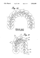
- FIG. 1 is a perspective view, part broken away, of a portion of a conveyor system embodying the principles of the present invention
- FIG. 2 is a enlarged bottom view of a portion of the conveyor shown in FIG. 1;
- FIG. 3 is a sectional view taken along line 3--3 in FIG. 1;
- FIG. 4 is an enlarged sectional view taken along line 4--4 in FIG. 1;
- FIG. 5 is an exploded perspective view of a portion of the conveyor track shown in FIG. 1;
- FIG. 6 is a perspective view of a load carrying member in accordance with the invention.
- FIG. 7 is a sectional view taken along line 7--7 in FIG. 6;
- FIG. 8 is a sectional view taken along line 8--8 in FIG. 6;
- FIG. 9 is a bottom perspective view of the load carrying member shown in FIG. 6;
- FIG. 10 is a bottom view of a conveyor chain with load carrying members according to the prior art.
- FIG. 11 is a bottom view of a conveyor chain comprising a conventional hollow pin link chain having pivotally mounted thereon support members in accordance with the invention.
- FIGS. 1-5 a conveyor system in accordance with the invention shown generally as 10, which includes a conveyor chain 12 formed with a link-type drive chain 14 having a plurality of adjacently oriented article carrier members 16 pivotally interconnected therewith associated with one or more drive sprockets 20 or the like rotating in a horizontal plane adapted to impart longitudinal movement to the conveyor chain 12.
- the conveyor chain 12 and sprocket or sprockets 20 are supported and the conveyor chain 12 is guided for movement or travel along a pre-selected path by an associated support structure, generally designated 18, having one or more drive assemblies (not shown) operatively associated therewith.
- the structure 18 is adapted to guide the conveyor chain 12 for movement in a substantially horizontal plane along both linear and curved paths of travel in accordance with any operational environment.
- the support structure 18 and conveyor chain 12 are substantially identical in construction and operation throughout the entire length of the conveyor system 10, only a typical cross-section thereof is illustrated in the drawings and described herein, it being apparent that the description of said typical section will be applicable to the entire length of the conveyor system 10.
- the conveyor chain 12 of the invention is uniquely constructed to be suitable for systems intended to follow articulating irregular paths of travel which may include sharp bends and turn-arounds and drive sprockets of small diameter as well as being adapted for ready installation and maintenance.
- the conveyor chain 12 comprises a typical, preferably endless, link-type chain 14 having a train of upper and lower inner links 24 and upper and lower outer links 26 pivotally interconnected at generally uniformly spaced pivot points 22 by hollow pin rollerless or the like link connecting means 28 to articulate about transverse axes enabling the chain to be driven about end sprocket(s) 20 with ease, and an upper, substantially continuous flight formed with a plurality of adjacently oriented article carrier members 16 pivotally and releasably mounted on the link-type chain 14 at respective pivot joints 22 thereof.
- Each of the article carrier members 16 as will be hereinafter described in detail comprises a generally horizontally disposed load carrying platform 30 of suitable width, a guide frame structure 38 fixed to the bottom surface 33 of the platform and a connecting pin 40 secured to the article carrier member 16 projecting substantially perpendicularly outwardly from the bottom end thereof intermediate the ends of the guide frame structure 38.
- the load carrying platform 30 is constructed and arranged at its opposite ends to cooperate with like load carrying platforms 30 of immediately adjacent carrier members 16 in the conveyor chain 12 for relative articulating movement, preferably, while maintaining a substantial continuous upper surface;
- the guide frame structure 38 is constructed and arranged to cooperate both with immediately adjacent carrier members 16 to maintain the horizontal disposition thereof and with the support structure 18 to guide the travel of the conveyor chain 12;
- the connecting pin 40 is constructed for releasably interconnecting the load carrying member 16 with the link-type chain 14.
- the load carrying platform 30 is generally crescent-shaped having one end shaped to provide a semi-circular convex edge 34 and at its opposite end provided with a complementary semi-circular concave edge 36.
- the platform 30 of article carrier member 16 is free for support of articles, while on it opposite face 33 the guide frame structure 38 fixed below the associated platform 30 is configured as a generally horseshoe-shaped flange 42 with a pair of spaced, parallel coextensive sides 44 which in this instance, project beyond the concave edge 36 of the platform 30 intermediate the ends thereof with a cover 46 therebetween and serves to support the contiguous convex end of immediately adjacent carrier members 16 in the conveyor chain 12 and maintain the horizontal disposition of like platforms 30.
- the overall width of the guide frame structure 38 is such as to afford sufficient width of the platform 30 at each side thereof to engage slidably with the track flanges 56 of the support structure 18.
- the connecting pin 40 which, as indicated, projects outwardly from the opposite bottom end of the article carrier member 16, serves to facilitate simple manipulative coupling assembly of the article carrier members 16 and the link-type chain 14 at respective pivot joints 22 of the chain 14 to effect a reliable interlocked pivotal relationship of the coupled members 16 and 14.
- the chain link hollow pin connector 28 is internally cylindrical and defines a coupling socket receptive to the connecting pin 40 of substantially the same diameter so as to afford a freely sliding bearing fit therewith.
- the connecting pin 40 is of a length wherein the distal end portion projects from the hollow pin link connector 28 after coupling, the distal end portion of the connecting pin 40 having a spring-biased ball 48 recessed therein which protrudes an amount sufficient to provide an effective interlock for the coupled connecting pin 40--hollow pin link connector 28 without inhibiting the ability of the connecting pin 40 to freely pivot or rotate relative to the link connector 28. While the protruding spring-biased ball 48 provides an effective interlock for the coupled members, the spring-biased ball 48 may be readily manually depressed within the connecting pin 40 recess for effecting the initial coupling of the connecting pin 40 and chain link connector 28, or when desired, for ready separation of such members.
- the support structure 18 of the conveyor system 10 defines a path or course of travel along which the conveyor chain 12 in the form of a train of contiguous article carrier members 16 is transported.
- the path of travel defined by the support structure 18 is in the form of a closed loop or continuous endless circuit, although such a layout is not absolutely essential to effective operation of the conveyor system 10 in the broadest sense.
- the support structure 18 usually is mounted on a suitable base (not shown) which supports the conveyor system 10 a suitable distance above the floor depending on the structures associated therewith, e.g. work stations, other conveyors, etc.
- the support structure 18 is generally configured to define a longitudinally extending channel or trough 50 located centrally above a base member 52 along the paths of travel of the conveyor system 10.
- a pair of laterally spaced generally vertically disposed guide track structures 54 are preferably, although not necessarily, coextensive with the base member 52, e.g. sections associated with drive sprockets and the like.
- the uppermost portions of the guide track structures 54 may be formed with substantially horizontally disposed, laterally inwardly extending flanges 56 which are disposed parallel to and separate from each other.
- Such flanges 56 define elongated side rails and the side limits of the conveyor system 10 path which, as indicated, may curve in any reasonable arrangement. While the various members of the support structure 18 may be fabricated from aluminum and the like and assembled by welding, riveting or other conventional means, metal extrusions configured as shown may be advantageously employed for many applications.
- flanges 56 Along the length of flanges 56 are securely mounted channel-shaped longitudinally extending wear strips 58 that may be fabricated from nylon or the like low friction, wear resistant plastic materials by extrusion or other conventional techniques. Such wear strips 58 are adapted to overlie the top and bottom surfaces 55 and 57, respectively, and the inner edges 59 of the flanges 56 to provide low-friction, self-lubricating running surfaces 60 for the outer edges of the platform 30 portion of article carrying members 16 as well as providing guide means 62 cooperating with the opposing parallel coextensive sides 44 of the guide frame structure 38 as the conveyor chain 12 travels along the path defined by the support structure 18.
- the channel configuration 50 of the support structure 18 serves as an unimpeding chain-way for the link-type chain 14 in the spacing between drive sprockets 20 and the like.
- the conveyor chains 12 of the invention are able to negotiate turns or bends of very short radii with ease, thus making possible the use of drive sprockets 20 and the like of small diameter; the conveyor chain 12 can be readily assembled or disassembled and/or individual article carrier members 16 readily replaced when desired; articles may be conveniently placed upon and removed from the conveyor platforms 30 traveling therealong; and the conveyor chains 12 travels smoothly and rapidly without the need for external lubrication.
- FIGS. 10 and 11 there is shown a conveyor chain having a plurality of adjacently oriented crescent-shaped load carrying members generally known in the prior art which are directly secured to the chain link connectors at respective chain pivot joints and in FIG. 11 there is shown a conveyor chain 12 of the present invention having a plurality of load carrying members 16 with platforms 30 of generally similar shape to those shown in FIG. 10 which are pivotally and releasably coupled to the chain link connectors 28 at respective pivot joints 22 of the chain 14 as herein described.
- the novel conveyor chain construction herein described can negotiate sharp turns and turn-arounds with significantly sharper radii than previously possible and conveyor systems may, for example, be configured with sprockets or the like drive means of very small diameter.
- an article carrying member 16 in accordance with the invention which comprises, as indicated, a load carrying platform 30 having a generally planar load carrying upper face 32, a guide frame structure 38 extending from the face 33 of the platform 30 opposite the upper face 32, and a connecting pin 40 projecting substantially perpendicularly outwardly from the load carrying member 16 within the area defined by the guide frame structure 38 and intermediate the ends thereof.
- the platform 30 is generally crescent-shaped in plan view, constructed and arranged at its opposite ends to cooperate with like platforms 30 of immediately adjacent carrying members 16 in a chain conveyor 12 for relative articulated movements.
- the platform 30 has one arcuate-shaped convex edge 34 which lies substantially along the circumference of a circle about the center of connecting pin 40.
- the platform 30 is provided with an arcuate-shaped concave edge 36 which lies substantially along the circumference of a circle about the center of the connecting pin 40 of a next succeeding article carrying member 16 (see FIGS. 1 and 2), which is also the center of the circle defining the convex edge 34 of that next succeeding article carrying member 16.
- the platforms 30 have a complementary configuration and provide a substantially flat, continuous article supporting surface when such members are assembled in a conveyor chain 12 in the manner illustrated in FIG. 1. Moreover, with the convex and concave edges 34 and 36 of the platform 30 blended in at their ends as shown, each platform 30 can turn with respect to the next adjacent platform 30 when traversing a curved course without substantially reducing the overall area of the article carrying surfaces or with gaps opening between them.
- the article carrying member 16 comprises a generally horseshoe shaped guide frame structure 38 which is disposed below and integral with the platform 30 substantially equidistant from the opposite sides thereof, having a pair of spaced, parallel coextensive sides 44 which project beyond the concave edge 36 of the platform, a flat cover member 46 extending between the sides 44 projecting beyond the edge 36 of platform 30 and a web member 47 which bridges the coextensive sides 44 intermediate the opposite ends of the frame structure 38.
- the flat cover member 46 is adapted to support the contiguous complimentary convex end of an immediately adjacent like platform 30 in a conveyor chain 12 to assist in maintaining the horizontal disposition of the platform while the coextensive parallel sides 44 of the guide frame structure 38 are adapted to cooperate with the guide means 62 of an associated support structure 18.
- the pin receptor 41 portion of the web member 47 which is at the center of the circle defining the arcuate convex edge 34 of the platform 30, extends below the cover plate member 46 from a point generally tangent to the arcuate concave edge 36 of the platform 30 equidistant from the ends thereof.
- the article carrying member 16, as seen in FIGS. 6 to 9, may be fabricated of any suitable strong, rigid plastic material such as polycarbonate, nylon or the like by conventional molding techniques with the platform 30 and guide frame structure 38 elements together with the connecting pin 40 being integrally formed as shown.
- the platform 30 and guide frame structure 38 may be separately fabricated of suitable metals such as aluminum or stainless steel, plywood, compositions flake board or the like and then assembled by conventional means.
- the configuration of the platform 30 is crescent shaped and the guide frame structure 38 is horseshoe shaped as herein shown, it would be evident that the configuration thereof may be varied according to the particular application e.g., the size and course of the conveyor system and the conveyor chain, the weight of articles to be transported, the type of support structure employed and like factors.
- Connecting pin 40 which, as indicated, projects outwardly from the load carrying member 16 and serves to facilitate coupling assembly of the article carrier member 16 and a link-type chain 14, is configured to effect a reliable interlocked pivotal relationship with the chain, which coupling assembly, however, can be readily separated when desired e.g., to replace the load carrying member 16 or revise the configuration of the conveyor chain 12.
- the connecting pin 40 is secured at one end to the load carrying member 16 by virtue of being retained within the pin receptor 41 element of the web member 47 portion of the guide frame structure 38.
- the distal end of the connecting pin 40 has a spring-biased ball 48 recessed therein which may be readily manually depressed within the recess for insertion of the pin shaft through a mating part but protrudes from the pin shaft an amount sufficient to provide an effective interlock with a coupled member.
- the connecting pin 40 is of a diameter which would permit the insertion thereof through a link connector for a link-type chain 14, such as an internally cylindrical hollow pin link connector 28, which is of substantially the same diameter and defines a coupling socket receptive of the connecting pin 40 so as to afford a freely sliding bearing fit therewith, and is of a length wherein the distal end portion thereof projects from link connector 28 after coupling an amount sufficient for the recessed spring-biased ball 48 to provide an effective interlock therefore.
- conveyor chains may employ conventional chains which can be readily converted to the desired conveyor system by the simple and ready incorporation of load carrying members.
- the load carrying members of the invention can not only be used to form the flight of a conveyor chain but can be readily removed from the conveyor chain for the purpose of maintenance or revision of the system.
Abstract
Description
Claims (7)
Priority Applications (1)
| Application Number | Priority Date | Filing Date | Title |
|---|---|---|---|
| US07/441,249 US5042648A (en) | 1989-11-27 | 1989-11-27 | Crescent-type chain conveyor |
Applications Claiming Priority (1)
| Application Number | Priority Date | Filing Date | Title |
|---|---|---|---|
| US07/441,249 US5042648A (en) | 1989-11-27 | 1989-11-27 | Crescent-type chain conveyor |
Publications (1)
| Publication Number | Publication Date |
|---|---|
| US5042648A true US5042648A (en) | 1991-08-27 |
Family
ID=23752130
Family Applications (1)
| Application Number | Title | Priority Date | Filing Date |
|---|---|---|---|
| US07/441,249 Expired - Lifetime US5042648A (en) | 1989-11-27 | 1989-11-27 | Crescent-type chain conveyor |
Country Status (1)
| Country | Link |
|---|---|
| US (1) | US5042648A (en) |
Cited By (31)
| Publication number | Priority date | Publication date | Assignee | Title |
|---|---|---|---|---|
| US5201407A (en) * | 1991-11-14 | 1993-04-13 | Carl Schenck Ag | Steel plate conveyor with drive |
| US5394978A (en) * | 1993-09-29 | 1995-03-07 | G&T Conveyor Company, Inc. | Plate-type conveyor utilizing improved power applying means |
| US5678682A (en) * | 1994-09-09 | 1997-10-21 | Mcc Nederland B.V. | Chain for a chain conveyor, and conveying system comprising such chain |
| US5749383A (en) * | 1994-08-02 | 1998-05-12 | Grapar Corporation | Non-linear chain belt type conveyor |
| US6016901A (en) * | 1997-01-27 | 2000-01-25 | Soot; Olaf | Chained movable platforms for people and objects |
| EP1092656A1 (en) * | 1999-10-15 | 2001-04-18 | BRECO Antriebstechnik Breher GmbH & Co. | Transport device |
| WO2001079086A1 (en) * | 2000-04-13 | 2001-10-25 | Yamakyu Chain Co., Ltd. | Frame material of conveyor system, running frame device using the frame material, and running rail mounting structure of conveyor system |
| WO2003022712A1 (en) * | 2001-09-05 | 2003-03-20 | Joh. Winklhofer & Söhne GmbH und Co. KG | Slat conveyor chain |
| US6640957B2 (en) * | 2001-12-21 | 2003-11-04 | Otis Elevator Company | Racetrack style passenger conveyor |
| NL1024501C2 (en) | 2003-08-07 | 2005-02-08 | Vanderlande Ind Nederland | Device for transporting products. |
| US20060151300A1 (en) * | 2002-11-12 | 2006-07-13 | Blasi Rene L | Pallet for conveyor chain |
| US20080110726A1 (en) * | 2006-09-29 | 2008-05-15 | Siemens Aktiengesellschaft | Drive for a conveyor, in particular baggage conveyor in airports |
| EP2096015A1 (en) * | 2008-02-26 | 2009-09-02 | ChairkiD Fördertechnik GmbH | Ski lift with auxiliary moving base |
| US20090260958A1 (en) * | 2006-08-25 | 2009-10-22 | Tsubaki Yamakyu Chain Co., Ltd. | Track frame assembly in conveyor system |
| US20100162916A1 (en) * | 2007-05-22 | 2010-07-01 | Alexander Lechner | Transport system |
| US20100282575A1 (en) * | 2009-05-08 | 2010-11-11 | Alit S.R.L. | Device for transmitting motion for conveyor belts |
| ES2401206A1 (en) * | 2012-12-27 | 2013-04-17 | Thyssenkrupp Elevator Innovation Center, S. A. | Turning system for belt transport system |
| WO2014018544A1 (en) | 2012-07-24 | 2014-01-30 | Laitram, L.L.C. | Conveyor belt for product stabilization |
| US20140251767A1 (en) * | 2013-03-07 | 2014-09-11 | John Edward Cleaves | Compact Conveyor System |
| US20150122757A1 (en) * | 2013-11-05 | 2015-05-07 | Three Paths, LLC | Moveable organizer |
| TWI559953B (en) * | 2014-09-16 | 2016-12-01 | ||
| TWI559955B (en) * | 2014-09-16 | 2016-12-01 | ||
| US20170036861A1 (en) * | 2015-08-06 | 2017-02-09 | System Plast S.Rl. | Curvilinear support for chain conveyors |
| US9884724B1 (en) * | 2013-04-16 | 2018-02-06 | Illinois Tool Works Inc. | Conveyor belt and platform for conveyor belt |
| US9938732B1 (en) * | 2015-03-12 | 2018-04-10 | Boston Whaler, Inc. | Articulating staging system for manufacturing |
| DE102017004820B3 (en) | 2017-05-18 | 2018-09-27 | Interroll Holding Ag | Transport attachment, traction means, plate conveyor and method |
| DE102017011071A1 (en) * | 2017-11-29 | 2019-05-29 | Interroll Holding Ag | Transport attachment, traction means, plate conveyor and method |
| CN109906194A (en) * | 2016-11-08 | 2019-06-18 | 创新专利有限公司 | The conveying device being made of multiple conveying band sections tactic each other |
| US20190248586A1 (en) * | 2018-02-09 | 2019-08-15 | Honda Motor Co., Ltd. | Carriage-utilizing conveying equipment |
| DE102018001569A1 (en) * | 2018-02-28 | 2019-08-29 | Interroll Holding Ag | Transport attachment, traction means, plate conveyor and method |
| US10988348B1 (en) * | 2020-05-26 | 2021-04-27 | Otis Elevator Company | Escalator steps with strain sensors |
Citations (17)
| Publication number | Priority date | Publication date | Assignee | Title |
|---|---|---|---|---|
| US1757652A (en) * | 1925-12-01 | 1930-05-06 | Miller Mfg Company | Metal-belt conveyer |
| US1800663A (en) * | 1926-10-14 | 1931-04-14 | Chain Belt Co | Conveyer flight |
| US1973750A (en) * | 1931-09-05 | 1934-09-18 | Richard E De Kay | Tray conveyer |
| US2150610A (en) * | 1937-05-12 | 1939-03-14 | Estral J Raffetto | Conveyer table |
| FR1008491A (en) * | 1950-01-18 | 1952-05-19 | Endless chain with scales | |
| US2705073A (en) * | 1952-11-10 | 1955-03-29 | A J Bayer Company | Conveyor |
| US3185108A (en) * | 1963-07-10 | 1965-05-25 | C F Butz Engineering | Pedestrian carrier |
| US3317030A (en) * | 1965-03-23 | 1967-05-02 | Alpeda Ind Inc | Articulated-section conveyor structure |
| US3379300A (en) * | 1965-10-24 | 1968-04-23 | Stearns Mfg Company Inc | Moving sidewalk |
| US3395648A (en) * | 1965-06-04 | 1968-08-06 | Fed Engineering Company | Moving sidewalk |
| US3399758A (en) * | 1966-08-08 | 1968-09-03 | Fed Engineering Company Inc | Moving sidewalk |
| US3493097A (en) * | 1966-08-08 | 1970-02-03 | Federal Eng Co | Moving sidewalk |
| US3498445A (en) * | 1967-10-30 | 1970-03-03 | Stearns Mfg Co | Conveyor drive means |
| US3554360A (en) * | 1968-08-12 | 1971-01-12 | Seatech Engineering | Conveyor |
| US3595377A (en) * | 1969-10-10 | 1971-07-27 | Proctor & Schwartz Inc | Circulating ball conveyor |
| US3685637A (en) * | 1970-07-17 | 1972-08-22 | Seatech Engineering | Pallet |
| SU846423A1 (en) * | 1979-10-03 | 1981-07-15 | Волгоградское Специализированное Кон-Структорско-Технологическое Бюро Научно- Производственного Объединения "Комплекс"Министерства Тракторного И Сельскохо-Зяйственного Машиностроения Cccp | Horizontally closed conveyer |
-
1989
- 1989-11-27 US US07/441,249 patent/US5042648A/en not_active Expired - Lifetime
Patent Citations (17)
| Publication number | Priority date | Publication date | Assignee | Title |
|---|---|---|---|---|
| US1757652A (en) * | 1925-12-01 | 1930-05-06 | Miller Mfg Company | Metal-belt conveyer |
| US1800663A (en) * | 1926-10-14 | 1931-04-14 | Chain Belt Co | Conveyer flight |
| US1973750A (en) * | 1931-09-05 | 1934-09-18 | Richard E De Kay | Tray conveyer |
| US2150610A (en) * | 1937-05-12 | 1939-03-14 | Estral J Raffetto | Conveyer table |
| FR1008491A (en) * | 1950-01-18 | 1952-05-19 | Endless chain with scales | |
| US2705073A (en) * | 1952-11-10 | 1955-03-29 | A J Bayer Company | Conveyor |
| US3185108A (en) * | 1963-07-10 | 1965-05-25 | C F Butz Engineering | Pedestrian carrier |
| US3317030A (en) * | 1965-03-23 | 1967-05-02 | Alpeda Ind Inc | Articulated-section conveyor structure |
| US3395648A (en) * | 1965-06-04 | 1968-08-06 | Fed Engineering Company | Moving sidewalk |
| US3379300A (en) * | 1965-10-24 | 1968-04-23 | Stearns Mfg Company Inc | Moving sidewalk |
| US3399758A (en) * | 1966-08-08 | 1968-09-03 | Fed Engineering Company Inc | Moving sidewalk |
| US3493097A (en) * | 1966-08-08 | 1970-02-03 | Federal Eng Co | Moving sidewalk |
| US3498445A (en) * | 1967-10-30 | 1970-03-03 | Stearns Mfg Co | Conveyor drive means |
| US3554360A (en) * | 1968-08-12 | 1971-01-12 | Seatech Engineering | Conveyor |
| US3595377A (en) * | 1969-10-10 | 1971-07-27 | Proctor & Schwartz Inc | Circulating ball conveyor |
| US3685637A (en) * | 1970-07-17 | 1972-08-22 | Seatech Engineering | Pallet |
| SU846423A1 (en) * | 1979-10-03 | 1981-07-15 | Волгоградское Специализированное Кон-Структорско-Технологическое Бюро Научно- Производственного Объединения "Комплекс"Министерства Тракторного И Сельскохо-Зяйственного Машиностроения Cccp | Horizontally closed conveyer |
Cited By (54)
| Publication number | Priority date | Publication date | Assignee | Title |
|---|---|---|---|---|
| US5201407A (en) * | 1991-11-14 | 1993-04-13 | Carl Schenck Ag | Steel plate conveyor with drive |
| US5394978A (en) * | 1993-09-29 | 1995-03-07 | G&T Conveyor Company, Inc. | Plate-type conveyor utilizing improved power applying means |
| US5749383A (en) * | 1994-08-02 | 1998-05-12 | Grapar Corporation | Non-linear chain belt type conveyor |
| US6065482A (en) * | 1994-08-02 | 2000-05-23 | Grapar Corporation | Non-linear chain belt type conveyor |
| USRE38543E1 (en) | 1994-09-09 | 2004-07-06 | Rexnord Flattop Europe B.V. | Chain for a chain conveyor, and conveying system comprising such chain |
| US5678682A (en) * | 1994-09-09 | 1997-10-21 | Mcc Nederland B.V. | Chain for a chain conveyor, and conveying system comprising such chain |
| US6016901A (en) * | 1997-01-27 | 2000-01-25 | Soot; Olaf | Chained movable platforms for people and objects |
| EP1092656A1 (en) * | 1999-10-15 | 2001-04-18 | BRECO Antriebstechnik Breher GmbH & Co. | Transport device |
| WO2001079086A1 (en) * | 2000-04-13 | 2001-10-25 | Yamakyu Chain Co., Ltd. | Frame material of conveyor system, running frame device using the frame material, and running rail mounting structure of conveyor system |
| US6854397B2 (en) | 2000-04-13 | 2005-02-15 | Yamakyu Chain Co., Ltd. | Frame member with traveling rail used in conveyor system and traveling frame assembly using the same |
| WO2003022712A1 (en) * | 2001-09-05 | 2003-03-20 | Joh. Winklhofer & Söhne GmbH und Co. KG | Slat conveyor chain |
| US20040245076A1 (en) * | 2001-09-05 | 2004-12-09 | Peter Grabmann | Slat conveyor chain |
| US6981584B2 (en) * | 2001-09-05 | 2006-01-03 | Joh. Winklhofer & Sohne Gmbh Und Co. Kg | Slat conveyor chain |
| US6640957B2 (en) * | 2001-12-21 | 2003-11-04 | Otis Elevator Company | Racetrack style passenger conveyor |
| US20060151300A1 (en) * | 2002-11-12 | 2006-07-13 | Blasi Rene L | Pallet for conveyor chain |
| WO2005019069A1 (en) * | 2003-08-07 | 2005-03-03 | Vanderlande Industries Nederland B.V. | Product conveyor with load-carrying platforms |
| NL1024501C2 (en) | 2003-08-07 | 2005-02-08 | Vanderlande Ind Nederland | Device for transporting products. |
| US7588140B2 (en) | 2003-08-07 | 2009-09-15 | Vanderlande Industries Nederland B.V. | Product conveyor with load-carrying platforms |
| US20090260958A1 (en) * | 2006-08-25 | 2009-10-22 | Tsubaki Yamakyu Chain Co., Ltd. | Track frame assembly in conveyor system |
| US8051976B2 (en) | 2006-08-25 | 2011-11-08 | Tsubaki Yamakyu Chain Co., Ltd. | Track frame assembly in conveyor system |
| US20080110726A1 (en) * | 2006-09-29 | 2008-05-15 | Siemens Aktiengesellschaft | Drive for a conveyor, in particular baggage conveyor in airports |
| US20100162916A1 (en) * | 2007-05-22 | 2010-07-01 | Alexander Lechner | Transport system |
| EP2096015A1 (en) * | 2008-02-26 | 2009-09-02 | ChairkiD Fördertechnik GmbH | Ski lift with auxiliary moving base |
| US20090260949A1 (en) * | 2008-02-26 | 2009-10-22 | Manfred Huber | Ski lift having an auxiliary conveyor floor |
| US20100282575A1 (en) * | 2009-05-08 | 2010-11-11 | Alit S.R.L. | Device for transmitting motion for conveyor belts |
| EP2877414A4 (en) * | 2012-07-24 | 2016-04-27 | Laitram Llc | Conveyor belt for product stabilization |
| WO2014018544A1 (en) | 2012-07-24 | 2014-01-30 | Laitram, L.L.C. | Conveyor belt for product stabilization |
| CN104603035B (en) * | 2012-07-24 | 2017-09-26 | 莱特拉姆有限责任公司 | The conveyer belt stable for product |
| US9527671B2 (en) | 2012-07-24 | 2016-12-27 | Laitram, L.L.C. | Conveyor belt for product stabilization |
| CN104603035A (en) * | 2012-07-24 | 2015-05-06 | 莱特拉姆有限责任公司 | Conveyor belt for product stabilization |
| ES2401206A1 (en) * | 2012-12-27 | 2013-04-17 | Thyssenkrupp Elevator Innovation Center, S. A. | Turning system for belt transport system |
| US9758352B2 (en) | 2012-12-27 | 2017-09-12 | Thyssenkrupp Elevator Innovation Center, S.A. | Turning system for belt transport system |
| WO2014102040A1 (en) * | 2012-12-27 | 2014-07-03 | Thyssenkrupp Elevator Innovation Center, S.A. | Turning system for belt transport system |
| CN109607363A (en) * | 2012-12-27 | 2019-04-12 | 蒂森克虏伯电梯创新中心股份公司 | For the steering system with conveyer system |
| US20140251767A1 (en) * | 2013-03-07 | 2014-09-11 | John Edward Cleaves | Compact Conveyor System |
| US9174803B2 (en) * | 2013-03-07 | 2015-11-03 | John Edward Cleaves | Compact conveyor system |
| US9884724B1 (en) * | 2013-04-16 | 2018-02-06 | Illinois Tool Works Inc. | Conveyor belt and platform for conveyor belt |
| US20150122757A1 (en) * | 2013-11-05 | 2015-05-07 | Three Paths, LLC | Moveable organizer |
| TWI559953B (en) * | 2014-09-16 | 2016-12-01 | ||
| TWI559955B (en) * | 2014-09-16 | 2016-12-01 | ||
| US9938732B1 (en) * | 2015-03-12 | 2018-04-10 | Boston Whaler, Inc. | Articulating staging system for manufacturing |
| US20170036861A1 (en) * | 2015-08-06 | 2017-02-09 | System Plast S.Rl. | Curvilinear support for chain conveyors |
| US9815631B2 (en) * | 2015-08-06 | 2017-11-14 | System Plast S.Rl. | Curvilinear support for chain conveyors |
| CN109906194A (en) * | 2016-11-08 | 2019-06-18 | 创新专利有限公司 | The conveying device being made of multiple conveying band sections tactic each other |
| US10633188B2 (en) * | 2016-11-08 | 2020-04-28 | Innova Patent Gmbh | Conveying device consisting of a plurality of conveyor-belt segments lined up adjacent to each other |
| DE102017004820B3 (en) | 2017-05-18 | 2018-09-27 | Interroll Holding Ag | Transport attachment, traction means, plate conveyor and method |
| US11046523B2 (en) | 2017-05-18 | 2021-06-29 | Interroll Holding Ag | Plate conveyor and transport attachment for such a plate conveyor |
| DE102017011071A1 (en) * | 2017-11-29 | 2019-05-29 | Interroll Holding Ag | Transport attachment, traction means, plate conveyor and method |
| DE102017011071B4 (en) | 2017-11-29 | 2019-06-19 | Interroll Holding Ag | Transport attachment, traction means, plate conveyor and method |
| US20190248586A1 (en) * | 2018-02-09 | 2019-08-15 | Honda Motor Co., Ltd. | Carriage-utilizing conveying equipment |
| US10472175B2 (en) * | 2018-02-09 | 2019-11-12 | Honda Motor Co., Ltd. | Carriage-utilizing conveying equipment |
| DE102018001569A1 (en) * | 2018-02-28 | 2019-08-29 | Interroll Holding Ag | Transport attachment, traction means, plate conveyor and method |
| DE102018001569B4 (en) * | 2018-02-28 | 2019-10-31 | Interroll Holding Ag | Transport attachment, traction means, plate conveyor and method |
| US10988348B1 (en) * | 2020-05-26 | 2021-04-27 | Otis Elevator Company | Escalator steps with strain sensors |
Similar Documents
| Publication | Publication Date | Title |
|---|---|---|
| US5042648A (en) | Crescent-type chain conveyor | |
| US5004097A (en) | Replaceable snap-on modular overlay for rod and link turn-curve conveyor belts | |
| US4645070A (en) | Dual bend conveyor | |
| US5775480A (en) | Low-friction conveyor assembly | |
| EP0734978B1 (en) | Chain propelled belt conveyor | |
| US4358010A (en) | Conveyor | |
| US6758328B2 (en) | Chain for three-dimensional transfer line | |
| MX2012006596A (en) | Conveyor transfer system with floating transfer platform. | |
| US5330045A (en) | Low backline pressure chain | |
| US4754872A (en) | Conveyor chain link | |
| EP0635441A1 (en) | Conveyor chain | |
| US3627109A (en) | Conveyor construction | |
| US2753039A (en) | Conveyor construction | |
| US5303817A (en) | Drive system for modular link conveyor belts | |
| US4765440A (en) | Food service conveyor | |
| US4909381A (en) | Shavings conveyor | |
| GB2172870A (en) | A conveying apparatus | |
| US5992615A (en) | Curved conveyor section | |
| US2725975A (en) | Conveyor mechanism | |
| US3498445A (en) | Conveyor drive means | |
| WO1987003565A1 (en) | Arrangement in a belt conveyor | |
| JP3443565B2 (en) | Transportation equipment | |
| US3306430A (en) | Belt-chain combination drive | |
| GB1000748A (en) | Conveyor drive apparatus | |
| US5593019A (en) | Chain return support |
Legal Events
| Date | Code | Title | Description |
|---|---|---|---|
| AS | Assignment |
Owner name: GARVEY CORPORATION, ROUTE 73, BLUE ANCHOR, NJ 0803 Free format text: ASSIGNMENT OF ASSIGNORS INTEREST.;ASSIGNOR:GARVEY, FRANCIS J.;REEL/FRAME:005187/0434 Effective date: 19891110 |
|
| STCF | Information on status: patent grant |
Free format text: PATENTED CASE |
|
| AS | Assignment |
Owner name: NEW JERSEY NATIONAL BANK, NEW JERSEY Free format text: ASSIGNMENT OF ASSIGNORS INTEREST;ASSIGNOR:GARVEY CORPORATION;REEL/FRAME:007023/0359 Effective date: 19940510 |
|
| FPAY | Fee payment |
Year of fee payment: 4 |
|
| REFU | Refund |
Free format text: REFUND - PAYMENT OF MAINTENANCE FEE, 4TH YR, SMALL ENTITY (ORIGINAL EVENT CODE: R283); ENTITY STATUS OF PATENT OWNER: SMALL ENTITY |
|
| FPAY | Fee payment |
Year of fee payment: 8 |
|
| FPAY | Fee payment |
Year of fee payment: 12 |