EP1590273B1 - Pallet for conveyor chain - Google Patents
Pallet for conveyor chain Download PDFInfo
- Publication number
- EP1590273B1 EP1590273B1 EP03813168A EP03813168A EP1590273B1 EP 1590273 B1 EP1590273 B1 EP 1590273B1 EP 03813168 A EP03813168 A EP 03813168A EP 03813168 A EP03813168 A EP 03813168A EP 1590273 B1 EP1590273 B1 EP 1590273B1
- Authority
- EP
- European Patent Office
- Prior art keywords
- chain
- plate
- pallet
- conveyor
- pallets
- Prior art date
- Legal status (The legal status is an assumption and is not a legal conclusion. Google has not performed a legal analysis and makes no representation as to the accuracy of the status listed.)
- Expired - Lifetime
Links
- 238000006073 displacement reaction Methods 0.000 abstract 1
- 206010064031 Limb crushing injury Diseases 0.000 description 1
- 230000003100 immobilizing effect Effects 0.000 description 1
- 230000001939 inductive effect Effects 0.000 description 1
- 238000009434 installation Methods 0.000 description 1
- 238000004519 manufacturing process Methods 0.000 description 1
- 238000010008 shearing Methods 0.000 description 1
- 229920002994 synthetic fiber Polymers 0.000 description 1
Images


Classifications
-
- B—PERFORMING OPERATIONS; TRANSPORTING
- B65—CONVEYING; PACKING; STORING; HANDLING THIN OR FILAMENTARY MATERIAL
- B65G—TRANSPORT OR STORAGE DEVICES, e.g. CONVEYORS FOR LOADING OR TIPPING, SHOP CONVEYOR SYSTEMS OR PNEUMATIC TUBE CONVEYORS
- B65G17/00—Conveyors having an endless traction element, e.g. a chain, transmitting movement to a continuous or substantially-continuous load-carrying surface or to a series of individual load-carriers; Endless-chain conveyors in which the chains form the load-carrying surface
- B65G17/16—Conveyors having an endless traction element, e.g. a chain, transmitting movement to a continuous or substantially-continuous load-carrying surface or to a series of individual load-carriers; Endless-chain conveyors in which the chains form the load-carrying surface comprising individual load-carriers which are pivotally mounted, e.g. for free-swinging movement
- B65G17/18—Conveyors having an endless traction element, e.g. a chain, transmitting movement to a continuous or substantially-continuous load-carrying surface or to a series of individual load-carriers; Endless-chain conveyors in which the chains form the load-carrying surface comprising individual load-carriers which are pivotally mounted, e.g. for free-swinging movement and move in contact with a guiding surface
-
- B—PERFORMING OPERATIONS; TRANSPORTING
- B65—CONVEYING; PACKING; STORING; HANDLING THIN OR FILAMENTARY MATERIAL
- B65G—TRANSPORT OR STORAGE DEVICES, e.g. CONVEYORS FOR LOADING OR TIPPING, SHOP CONVEYOR SYSTEMS OR PNEUMATIC TUBE CONVEYORS
- B65G17/00—Conveyors having an endless traction element, e.g. a chain, transmitting movement to a continuous or substantially-continuous load-carrying surface or to a series of individual load-carriers; Endless-chain conveyors in which the chains form the load-carrying surface
- B65G17/06—Conveyors having an endless traction element, e.g. a chain, transmitting movement to a continuous or substantially-continuous load-carrying surface or to a series of individual load-carriers; Endless-chain conveyors in which the chains form the load-carrying surface having a load-carrying surface formed by a series of interconnected, e.g. longitudinal, links, plates, or platforms
- B65G17/065—Conveyors having an endless traction element, e.g. a chain, transmitting movement to a continuous or substantially-continuous load-carrying surface or to a series of individual load-carriers; Endless-chain conveyors in which the chains form the load-carrying surface having a load-carrying surface formed by a series of interconnected, e.g. longitudinal, links, plates, or platforms the load carrying surface being formed by plates or platforms attached to a single traction element
- B65G17/066—Conveyors having an endless traction element, e.g. a chain, transmitting movement to a continuous or substantially-continuous load-carrying surface or to a series of individual load-carriers; Endless-chain conveyors in which the chains form the load-carrying surface having a load-carrying surface formed by a series of interconnected, e.g. longitudinal, links, plates, or platforms the load carrying surface being formed by plates or platforms attached to a single traction element specially adapted to follow a curved path
-
- B—PERFORMING OPERATIONS; TRANSPORTING
- B65—CONVEYING; PACKING; STORING; HANDLING THIN OR FILAMENTARY MATERIAL
- B65G—TRANSPORT OR STORAGE DEVICES, e.g. CONVEYORS FOR LOADING OR TIPPING, SHOP CONVEYOR SYSTEMS OR PNEUMATIC TUBE CONVEYORS
- B65G17/00—Conveyors having an endless traction element, e.g. a chain, transmitting movement to a continuous or substantially-continuous load-carrying surface or to a series of individual load-carriers; Endless-chain conveyors in which the chains form the load-carrying surface
- B65G17/30—Details; Auxiliary devices
- B65G17/32—Individual load-carriers
- B65G17/34—Individual load-carriers having flat surfaces, e.g. platforms, grids, forks
-
- B—PERFORMING OPERATIONS; TRANSPORTING
- B65—CONVEYING; PACKING; STORING; HANDLING THIN OR FILAMENTARY MATERIAL
- B65G—TRANSPORT OR STORAGE DEVICES, e.g. CONVEYORS FOR LOADING OR TIPPING, SHOP CONVEYOR SYSTEMS OR PNEUMATIC TUBE CONVEYORS
- B65G17/00—Conveyors having an endless traction element, e.g. a chain, transmitting movement to a continuous or substantially-continuous load-carrying surface or to a series of individual load-carriers; Endless-chain conveyors in which the chains form the load-carrying surface
- B65G17/30—Details; Auxiliary devices
- B65G17/38—Chains or like traction elements; Connections between traction elements and load-carriers
- B65G17/42—Attaching load carriers to traction elements
Definitions
- the present invention relates to a pallet for a conveyor chain according to the preamble of claim 1, a pallet chain according to the preamble of claim 2 and a chain conveyor according to the preamble of claim 8.
- Pallets are fixed by any means, including integral, to chain links, usually bush links, roller or cardan.
- the axes of the bushings or rollers are arranged substantially vertically in the conveyor and the pallets are fixed to the linkage axes between links, so as to be horizontal.
- the bush chains have a good tensile strength which makes it possible to realize sinuous trajectories of great length. They also allow a drive from the side, particularly economical.
- Chain guidance is achieved by the links sliding in a profile or profile assembly.
- the curves of the trajectory are made possible by the shape of the pallets which allows them to orient themselves relative to each other in their plane.
- the vanes move between the guiding walls that protrude above their upper surface to guide the transported objects.
- this conveyor requires the use of two different types of pallets and their precise relative positioning, which is expensive in terms of manufacture and assembly.
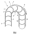
- Figure 1 shows another vane chain 1 of the prior art. This figure illustrates the fact that the maximization of the usable surface is generally obtained with pallets 2 whose front edge 3 and the rear edge 4 are substantially circular with the same radius, one of these edges being convex and the other concave. Various forms of pallets have already been made on this principle.
- edges 3 and 4 fit one into the other so that in both the straight portions such as in the curves such as 6, almost the entire area between the guide walls 7 is covered. by the pallets.
- the pallets depart and leave each other, in particular their lateral edges 7, and the guide walls 8 of the interstices 9.
- an object can be introduced inadvertently, or worse, the finger of an operator.
- the gap closes and may sever the trapped finger.
- the document DE 299 22 101 U also describes a conveyor in which the bearing surface has been increased, via the use of crescent-shaped pallets, the concave face of a pallet cooperating with the convex face of an adjacent pallet.
- US 2 181 659 A1 discloses a conveyor comprising disk-shaped pallets. The pallets overlap each other.
- the overlap of the pallets has the disadvantage of inducing a shearing movement as the pallet chain moves from a straight path to a curved path.
- this overlap uses the pallets.
- An object of the invention is to provide a pallet conveyor which eliminates the risk of jamming an object, and more particularly that does not present a danger to an operator.
- the invention avoids the risk of jamming, especially by providing that the surfaces defined above are not narrowed during the passage of a curved portion to a straight portion or vice versa.
- the links may be bushing links.
- At least one pallet is rotatable about an axis orthogonal to the plane of the pallets, with respect to the link of the chain carrying said pallet.
- At least one pallet is immobilized relative to the link of the chain carrying said pallet.
- each pallet may be carried by two adjacent bushing pins or, alternatively, carried by a single bushing axis, locking means of the rotation of the pallet about said axis being then provided.
- each pallet may be carried by two adjacent socket pins.
- the subject of the invention is a chain conveyor according to claim 8.
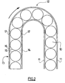
- the conveyor comprises a succession of pallets 10 of substantially identical shapes.
- the pallets 10 have a shape, circular in this way, that both in the curves of maximum radius 12 and in the straight portions 13, the space 14 delimited by the rear edge 15 of a pallet, the front edge 16 of the pallet which follows, the side edges 17 of these pallets and one of the guide walls 11, has a sufficient surface so that a finger of a user can not be pinched.
- the diameter of the pallets 10 is slightly smaller than the distance between the guide walls 11.
- the distance between the centers of two adjacent pallets 10 is slightly greater than the diameter of the pallets so that the front edge 15 of a pallet is the closest possible the rear edge 16 of the pallet that precedes and the driving surface of the conveyor is maximum.
- the pallets 10 are close to each other, but are spaced apart and do not overlap, which notably avoids the risk of wear. In addition, it is not provided between two successive pallets 10 of intermediate element that can cause jamming problems.
- each guide wall 11 is formed of one of the wings of an angle member 18.
- the other wing 19 of each angle 18 is attached to a support profile 20 with bolts 21 cooperating with nuts (not shown) engaged and held in upper grooves 22 of the support profile 20.
- the support profile 20 also includes two pairs of lateral grooves 23 for attaching accessories such as sensors or actuators, and two lower mounting grooves 24 for attaching the profile to any suitable installation support.
- the support profile 20 also forms two substantially horizontal support ribs 25 in the installed operating position, which extend from the outside of the profile towards its vertical plane of symmetry.
- the inner edges of the support ribs 25 define a longitudinal slot 26 and form a clipping profile 27.
- the support profile 20 finally forms a connecting profile 28 connecting transversely the two support ribs 25 below the longitudinal slot 26.
- the two support ribs 25 and the connecting profile 28 thus form a longitudinal box 29 open towards the high along the slit 26.
- Each sliding profile 30 covers the upper surface of one of the support ribs 25 and the corresponding edge of the longitudinal slot 26.
- the conveyor chain 31 is a known type bushing chain whose links 32 are connected by rivets 33 on which the bushes 34 are engaged.
- Each pallet 10 is mounted on the chain by means of two successive rivets 33.
- four successive rivets separate each group of two rivets carrying a pallet 10.
- Each pallet 10 is thus immobilized with respect to the chain and in particular can not pivot about its axis.
- This configuration is advantageous, in particular because it makes it possible to limit the wear of the pallets by the objects transported.
- the pallet 10 can be carried by a single bushing axis, locking means of the rotation of the pallet 10 about its axis being provided.
- the chain 31 is arranged on the support profile 20 so that the face of the pallets 10 located on the side of the chain rests on the sliding profiles 30, the chain extending in the box 28 through the slot 26 which ensures its guidance.
- Lateral drive means of any known type can drive the chain 31.
- the chain is guided by the pallets 10 which are themselves guided by the guide walls 11 of the brackets 18.
- the invention thus provides a chain conveyor having good mechanical qualities and furthermore not presenting any danger for its operators.
Abstract
Description
La présente invention concerne une palette pour chaîne de convoyeur selon le préambule de la revendication 1, une chaîne à palettes selon le préambule de la revendication 2 et un convoyeur à chaîne selon le preambule de la revendication 8.The present invention relates to a pallet for a conveyor chain according to the preamble of claim 1, a pallet chain according to the preamble of
On connaît déjà des convoyeurs utilisant des palettes de ce type. Ces convoyeurs sont par exemple utilisés dans des ateliers de mécanique pour déplacer des pièces d'un poste à un autre. Les palettes servent de support aux pièces transportées.Conveyors using pallets of this type are already known. These conveyors are for example used in mechanical workshops to move parts from one station to another. The pallets serve as support for the transported parts.
Les palettes sont fixées par tout moyen, y compris en en faisant partie intégrante, à des maillons de chaîne, généralement des maillons à douilles, à rouleaux ou à cardans. Dans le cas des chaînes à douilles ou à rouleaux, les axes des douilles ou des rouleaux sont disposés sensiblement verticalement dans le convoyeur et les palettes sont fixées aux axes de liaison entre maillons, de manière à se trouver horizontales.Pallets are fixed by any means, including integral, to chain links, usually bush links, roller or cardan. In the case of bushings or roller chains, the axes of the bushings or rollers are arranged substantially vertically in the conveyor and the pallets are fixed to the linkage axes between links, so as to be horizontal.
Les chaînes à douilles ont une bonne résistance à la traction qui permet de réaliser des trajectoires sinueuses de grande longueur. Elles permettent de plus un entraînement par le côté, particulièrement économique.The bush chains have a good tensile strength which makes it possible to realize sinuous trajectories of great length. They also allow a drive from the side, particularly economical.
Un autre avantage de ces chaînes à douilles réside dans le fait que la trajectoire des palettes peut être entièrement dans un plan horizontal, et donc utilisée sur toute sa longueur, sans brin de retour en dessous du brin utile.Another advantage of these bush chains lies in the fact that the trajectory of the pallets can be entirely in a horizontal plane, and therefore used throughout its length, without return strand below the useful strand.
Le guidage de la chaîne est réalisé par les maillons qui glissent dans un profilé ou un assemblage de profilés.Chain guidance is achieved by the links sliding in a profile or profile assembly.
Les courbes de la trajectoire sont rendues possibles par la forme des palettes qui leur permet de s'orienter les unes par rapport aux autres dans leur plan.The curves of the trajectory are made possible by the shape of the pallets which allows them to orient themselves relative to each other in their plane.
Les palettes se déplacent entre les parois de guidage qui font saillie au-dessus de leur surface supérieure pour guider les objets transportés.The vanes move between the guiding walls that protrude above their upper surface to guide the transported objects.
On s'attache dans la conception des palettes à ce que la plus grande surface utilisable possible soit disponible pour le support des objets à transporter, c'est-à-dire sensiblement toute la surface comprise entre les deux parois de guidage. On augmente ainsi les forces d'entraînement par friction des objets transportés sur les palettes.It is attached in the design of the pallets so that the largest usable surface possible is available for the support of the objects to be transported, that is to say substantially the entire area between the two guide walls. This increases the friction drive forces of the objects transported on the pallets.
Tel est le cas notamment pour le convoyeur décrit dans le document FR 2 297 788, qui prévoit de combler sensiblement totalement l'espace présent entre deux palettes successives par un élément intermédiaire en forme de papillon, afin d'augmenter la surface portante.This is particularly the case for the conveyor described in
Toutefois ce convoyeur présente un certain nombre d'inconvénients.However this conveyor has a number of disadvantages.
Lors du passage d'une portion droite du convoyeur à une portion courbe, l'espace entre deux éléments intermédiaires se rétrécie à l'intérieur de la courbe, pouvant entraîner le coincement d'un objet, en particulier le coincement d'un doigt. En outre, ce problème de coincement se pose également lors du passage d'une portion courbe du convoyeur à une portion droite. En effet, l'espace entre un élément intermédiaire et une palette adjacente, élargi à l'extérieur de la courbe, se rétrécie dans la portion droite.During the passage of a straight portion of the conveyor to a curved portion, the space between two intermediate elements narrows within the curve, which can cause the jamming of an object, in particular the jamming of a finger. In addition, this jamming problem also arises during the passage of a curved portion of the conveyor to a straight portion. Indeed, the space between an intermediate element and an adjacent pallet, widened outside the curve, narrows in the right portion.
Par ailleurs, ce convoyeur nécessite l'emploi de deux types de palettes différents et leur positionnement relatif précis, ce qui est coûteux en termes de fabrication et de montage.Moreover, this conveyor requires the use of two different types of pallets and their precise relative positioning, which is expensive in terms of manufacture and assembly.
La figure 1 montre une autre chaîne à palettes 1 de l'art antérieur. Cette figure illustre le fait que la maximisation de la surface utilisable est généralement obtenue avec des palettes 2 dont le bord avant 3 et le bord arrière 4 sont sensiblement circulaires de même rayon, l'un de ces bords étant convexe et l'autre concave. Diverses formes de palettes ont déjà été réalisées sur ce principe.Figure 1 shows another vane chain 1 of the prior art. This figure illustrates the fact that the maximization of the usable surface is generally obtained with
Ces bords 3 et 4 s'encastrent l'un dans l'autre de sorte que, tant dans les portions droites telles que 5 que dans les courbes telles que 6, à peu près toute la surface comprise entre les parois de guidage 7 est couverte par les palettes.These
On voit toutefois que, dans les zones courbes 6, les palettes s'écartent et laissent entre elles, notamment leurs bords latéraux 7, et les parois de guidage 8 des interstices 9. Dans ces interstices, un objet peut être introduit par inadvertance, ou, pire, le doigt d'un opérateur. Lorsque la palette arrive de nouveau dans une portion droite de sa trajectoire, l'interstice se referme et risque de sectionner le doigt emprisonné.However, it can be seen that, in the curved zones 6, the pallets depart and leave each other, in particular their
Le document DE 299 22 101 U décrit également un convoyeur dans lequel la surface portante a été augmentée, via l'utilisation de palettes en forme de croissant, la face concave d'une palette coopérant avec la face convexe d'une palette adjacente.The document DE 299 22 101 U also describes a conveyor in which the bearing surface has been increased, via the use of crescent-shaped pallets, the concave face of a pallet cooperating with the convex face of an adjacent pallet.
Là encore, dans une portion courbe du convoyeur, le déplacement des palettes les unes par rapport aux autres conduit à une augmentation de l'espace formé entre les palettes et l'enveloppe du bord extérieur des palettes, par rapport à une portion courbe du convoyeur. En conséquence, lors du retour en ligne droite, cet espace est rétréci, pouvant donc entraîner le coincement d'un objet.Again, in a curved portion of the conveyor, the movement of the pallets relative to each other leads to an increase in the space formed between the pallets and the envelope of the outer edge of the pallets, with respect to a curved portion of the conveyor . Consequently, when returning to a straight line, this space is narrowed, which can therefore cause the jamming of an object.
Le document US 2 181 659 A1 décrit un convoyeur comprennant des palettes en forme de disque. Les palettes se chevauchent les uns sur les autres.US 2 181 659 A1 discloses a conveyor comprising disk-shaped pallets. The pallets overlap each other.
Le chevauchement des palettes présente le désavantage d'induire un mouvement de cisaillement lorsque la chaîne de palettes passe d'une trajectoire rectiligne à une trajectoire courbe. De plus ce chevauchement use les palettes.The overlap of the pallets has the disadvantage of inducing a shearing movement as the pallet chain moves from a straight path to a curved path. In addition this overlap uses the pallets.
Un objectif de l'invention est de fournir un convoyeur à palettes qui élimine le risque de coincement d'un objet, et, plus particulièrement qui ne présente pas de danger pour un opérateur.An object of the invention is to provide a pallet conveyor which eliminates the risk of jamming an object, and more particularly that does not present a danger to an operator.
A cet effet, et selon un premier aspect de l'invention, celle-ci a pour objet une palette pour chaîne de convoyeur selon la revendication 1.For this purpose, and according to a first aspect of the invention, it relates to a pallet for a conveyor chain according to claim 1.
Ainsi, l'invention permet d'éviter les risques de coincement, notamment en prévoyant que les surfaces définies ci-dessus ne soient pas rétrécies lors du passage d'une portion courbe à une portion droite ou inversement.Thus, the invention avoids the risk of jamming, especially by providing that the surfaces defined above are not narrowed during the passage of a curved portion to a straight portion or vice versa.
On observera néanmoins que dans tous les cas, il est renoncé au principe usuel de l'art antérieur selon lequel la surface occupée par les palettes entre les parois de guidage doit être maximale, notamment dans les portions droites du convoyeur.It will nevertheless be observed that in all cases, it is waived the usual principle of the prior art that the area occupied by the pallets between the guide walls must be maximum, especially in the straight portions of the conveyor.
Selon un autre aspect de l'invention, celle-ci a pour objet une chaîne à palettes selon la revendication 2.According to another aspect of the invention, it relates to a vane chain according to
Dans un mode de réalisation particulier, les maillons peuvent être des maillons à douilles.In a particular embodiment, the links may be bushing links.
Dans une réalisation, au moins une palette est mobile en rotation autour d'un axe orthogonal au plan des palettes, par rapport au maillon de la chaîne portant ladite palette.In one embodiment, at least one pallet is rotatable about an axis orthogonal to the plane of the pallets, with respect to the link of the chain carrying said pallet.
Dans une autre réalisation, au moins une palette est immobilisée par rapport au maillon de la chaîne portant ladite palette.In another embodiment, at least one pallet is immobilized relative to the link of the chain carrying said pallet.
A cet effet, chaque palette peut être portée par deux axes de douille adjacents ou, en variante, portée par un unique axe de douille, des moyens de blocage de la rotation de la palette autour dudit axe étant alors prévus.For this purpose, each pallet may be carried by two adjacent bushing pins or, alternatively, carried by a single bushing axis, locking means of the rotation of the pallet about said axis being then provided.
Plus particulièrement, chaque palette peut être portée par deux axes de douille adjacents.More particularly, each pallet may be carried by two adjacent socket pins.
Selon encore un autre aspect de l'invention, celle-ci a pour objet un convoyeur à chaîne selon la revendication 8.According to yet another aspect of the invention, the subject of the invention is a chain conveyor according to
On décrira maintenant, à titre d'exemple non limitatif, un mode de réalisation particulier de l'invention, en référence aux dessins schématiques annexés dans lesquels :
- la figure 1 est une vue de dessus d'un convoyeur de l'art antérieur et a déjà été décrite ;
- la figure 2 est une vue similaire à la figure 1 d'un convoyeur selon l'invention ;
- la figure 3 est une vue en perspective d'une portion de ce convoyeur ;
- la figure 4 en est une vue en coupe transversale ; et
- la figure 5 en est une autre vue en perspective.
- Figure 1 is a top view of a conveyor of the prior art and has already been described;
- Figure 2 is a view similar to Figure 1 of a conveyor according to the invention;
- Figure 3 is a perspective view of a portion of this conveyor;
- Figure 4 is a cross-sectional view; and
- Figure 5 is another perspective view.
On voit sur la figure 2 les palettes 10 et les parois de guidage 11 d'un convoyeur selon l'invention. Le convoyeur comprend une succession de palettes 10 de formes sensiblement identiques.We see in Figure 2 the
Les palettes 10 ont une forme telle, ici circulaire, qu'aussi bien dans les courbes de rayon maximal 12 que dans les parties droites 13, l'espace 14 délimité par le bord arrière 15 d'une palette, le bord avant 16 de la palette qui la suit, les bords latéraux 17 de ces palettes et une des parois de guidage 11, ait une surface suffisante pour qu'un doigt d'un utilisateur ne puisse y être pincé.The
Le diamètre des palettes 10 est légèrement inférieur à la distance entre les parois de guidage 11. La distance entre les centres de deux palettes 10 adjacentes est légèrement supérieure au diamètre des palettes de manière que le bord avant 15 d'une palette soit le plus proche possible du bord arrière 16 de la palette qui la précède et que la surface d'entraînement du convoyeur soit maximale.The diameter of the
Les palettes 10 sont proches les unes des autres, mais sont écartées et ne se chevauchent pas, ce qui évite notamment les risques d'usure. En outre, il n'est pas prévu entre deux palettes 10 successives d'élément intermédiaire pouvant engendrer des problèmes de coincement.The
Si l'on se réfère maintenant aux figures 3 à 5, on voit que chaque paroi de guidage 11 est formée d'une des ailes d'une cornière 18. L'autre aile 19 de chaque cornière 18 est fixée à un profilé de support 20 à l'aide de boulons 21 coopérant avec des écrous (non représentés) engagés et maintenus dans des rainures supérieures 22 du profilé de support 20.Referring now to FIGS. 3 to 5, it can be seen that each
Le profilé de support 20 comporte également deux paires de rainures latérales 23 pour la fixation d'accessoires tels que des capteurs ou des actionneurs, et deux rainures inférieures de montage 24 pour la fixation du profilé sur tout support de d'installation adéquat.The
Le profilé de support 20 forme par ailleurs deux nervures de support 25, sensiblement horizontales en position installée de fonctionnement, qui s'étendent depuis l'extérieur du profilé vers son plan vertical de symétrie. Les bords intérieurs des nervures de support 25 délimitent une fente longitudinale 26 et forment un profil de clipsage 27.The
Le profilé de support 20 forme enfin un profil de liaison 28 reliant transversalement les deux nervures de support 25 en-dessous de la fente longitudinale 26. Les deux nervures de support 25 et le profil de liaison 28 forment ainsi un caisson longitudinal 29 ouvert vers le haut le long de la fente 26.The
Un profilé de glissement 30, généralement en forme de U et réalisé en matière synthétique possédant de bonnes propriétés de glissement et de résistance à l'usure, est clipsé sur chaque profil 27. Chaque profilé de glissement 30 recouvre la surface supérieure d'une des nervures de support 25 ainsi que le bord correspondant de la fente longitudinale 26.A sliding
La chaîne de convoyeur 31 est une chaîne à douilles de type connu dont les maillons 32 sont reliés par des rivets 33 sur lesquels sont engagés les douilles 34.The
Chaque palette 10 est montée sur la chaîne à l'aide de deux rivets 33 successifs. Dans le cas présent, compte tenu des valeurs relatives du rayon des palettes 10 et de la distance entre les axes des rivets 33, quatre rivets successifs séparent chaque groupe de deux rivets porteurs d'une palette 10.Each
Chaque palette 10 est ainsi immobilisée par rapport à la chaîne et ne peut notamment pas pivoter autour de son axe. Cette configuration est avantageuse, notamment parce qu'elle permet de limiter l'usure des palettes par les objets transportés.Each
D'autres modes de réalisation permettant de fixer les palettes 10 à la chaîne sans rotation sont possibles. Par exemple, la palette 10 peut être portée par un unique axe de douille, des moyens de blocage de la rotation de la palette 10 autour de son axe étant prévus.Other embodiments for fixing the
On peut également prévoir un unique axe de douille portant la palette 10 sans moyen d'immobilisation de la palette par rapport à l'axe, donc par rapport à la chaîne.It is also possible to provide a single bushing axis carrying the
La chaîne 31 est disposée sur le profilé de support 20 de telle sorte que la face des palettes 10 située du côté de la chaîne repose sur les profilés de glissement 30, la chaîne s'étendant dans le caisson 28 à travers la fente 26 qui assure son guidage.The
Des moyens d'entraînement latéral de tout type connu (non représentés) permettent d'entraîner la chaîne 31. La chaîne est guidée par les palettes 10 qui sont elles-mêmes guidées par les parois de guidage 11 des cornières 18.Lateral drive means of any known type (not shown) can drive the
L'invention fournit ainsi un convoyeur à chaîne présentant de bonnes qualités mécaniques et en outre ne présentant pas de danger pour ses opérateurs.The invention thus provides a chain conveyor having good mechanical qualities and furthermore not presenting any danger for its operators.
Claims (10)
- A plate for a conveyor chain, which plate is arranged to be fastened to a drive chain (31) that is suitable for driving a succession of plates (10) substantially in a plane and in a drive direction along a path that can have straight portions (13) and portions of maximum curvature (12), said plate being characterized by the fact that the edges of the plates are substantially circular and of the same size, the distance between the centers of two adjacent plates (10) being slightly greater than the diameter of the plates.
- A plate chain comprising a succession of links (31), at least some of the links each carrying a respective plate (10), said plate chain being characterized in that said plate is a plate according to claim 1.
- A chain according to claim 2, in which the links are bush roller links.
- A chain according to claim 2 or claim 3, in which at least one plate is mounted to move in rotation about an axis that is orthogonal to the plane of the plates, relative to the link (31) of the chain that carries said plate.
- A chain according to claim 2 or claim 3, in which at least one plate is held stationary relative to the link (31) of the chain that carries said plate.
- A chain according to claims 3 and 5, in which each plate is carried by two adjacent bushing pins (33).
- A chain according to claims 3 and 5, in which each plate is carried by a single bushing pin (33), locking means being provided for preventing the plate from moving in rotation about said pin (33).
- A chain conveyor comprising a plate chain (31) and a support (18, 20) provided with guide walls (11), said chain conveyor being characterized by the fact that said chain is a chain according to claim 2.
- A conveyor according to claim 8, in which the links of the chain are roller bush links (34).
- A conveyor according to claim 9, in which each plate (10) is carried by two adjacent bushing pins (33).
Applications Claiming Priority (3)
| Application Number | Priority Date | Filing Date | Title |
|---|---|---|---|
| FR0215650A FR2848539B1 (en) | 2002-12-11 | 2002-12-11 | PALLET FOR CONVEYOR CHAIN |
| FR0215650 | 2002-12-11 | ||
| PCT/FR2003/003679 WO2004054902A1 (en) | 2002-12-11 | 2003-12-11 | Pallet for conveyor chain |
Publications (3)
| Publication Number | Publication Date |
|---|---|
| EP1590273A1 EP1590273A1 (en) | 2005-11-02 |
| EP1590273B1 true EP1590273B1 (en) | 2007-03-28 |
| EP1590273B8 EP1590273B8 (en) | 2007-08-08 |
Family
ID=32338677
Family Applications (1)
| Application Number | Title | Priority Date | Filing Date |
|---|---|---|---|
| EP03813168A Expired - Lifetime EP1590273B8 (en) | 2002-12-11 | 2003-12-11 | Pallet for conveyor chain |
Country Status (7)
| Country | Link |
|---|---|
| US (1) | US20060151300A1 (en) |
| EP (1) | EP1590273B8 (en) |
| AT (1) | ATE358082T1 (en) |
| AU (1) | AU2003296821A1 (en) |
| DE (1) | DE60312896D1 (en) |
| FR (1) | FR2848539B1 (en) |
| WO (1) | WO2004054902A1 (en) |
Families Citing this family (6)
| Publication number | Priority date | Publication date | Assignee | Title |
|---|---|---|---|---|
| US7355975B2 (en) * | 2004-04-30 | 2008-04-08 | International Business Machines Corporation | Method and apparatus for group communication with end-to-end reliability |
| CH704134A1 (en) | 2010-11-26 | 2012-05-31 | Ferag Ag | Funding system, carrier element and guide channel. |
| JP2014193761A (en) * | 2013-03-29 | 2014-10-09 | Toyota Industries Corp | Transportation device |
| ITUB20152972A1 (en) * | 2015-08-06 | 2015-11-06 | System Plast S R L | CURVILINEAR SUPPORT FOR CHAIN CONVEYORS |
| US10085676B1 (en) * | 2015-11-07 | 2018-10-02 | Bertec Corporation | Force measurement system |
| IT201800020248A1 (en) * | 2018-12-20 | 2020-06-20 | Cusinato Giovanni S R L Soc Unipersonale | CHAIN GUIDE FOR BUCKET CONVEYOR |
Family Cites Families (10)
| Publication number | Priority date | Publication date | Assignee | Title |
|---|---|---|---|---|
| FR723276A (en) * | 1930-10-16 | 1932-04-06 | Conveyor chain | |
| US2181659A (en) * | 1937-02-05 | 1939-11-28 | Joseph A Gage | Conveyer attachment |
| US3554360A (en) * | 1968-08-12 | 1971-01-12 | Seatech Engineering | Conveyor |
| AT336491B (en) * | 1973-08-04 | 1977-05-10 | Interroll Foerdertechnik Gmbh | DETACHABLE JOINT CHAIN |
| FR2297788A1 (en) * | 1975-01-16 | 1976-08-13 | Pelissier Pierre | Conveyor with load support discs between spacers - has pivot connections allowing movement of discs and spacers at conveyor curves |
| GB1529730A (en) * | 1975-12-08 | 1978-10-25 | Cosan Crisplant As | Conveyor systems |
| US5042648A (en) * | 1989-11-27 | 1991-08-27 | Garvey Corporation | Crescent-type chain conveyor |
| DE29922101U1 (en) * | 1999-12-16 | 2001-02-08 | Irmler Ingrid | Closed plate conveyor system for the transport of workpieces with at least one flat support surface |
| DE20114661U1 (en) * | 2001-09-05 | 2002-11-07 | Winklhofer & Soehne Gmbh | Plate conveyor chain |
| JP2004313501A (en) * | 2003-04-17 | 2004-11-11 | System Create:Kk | Circulating conveyor for food and drink |
-
2002
- 2002-12-11 FR FR0215650A patent/FR2848539B1/en not_active Expired - Fee Related
-
2003
- 2003-12-11 WO PCT/FR2003/003679 patent/WO2004054902A1/en active IP Right Grant
- 2003-12-11 DE DE60312896T patent/DE60312896D1/en not_active Expired - Lifetime
- 2003-12-11 AU AU2003296821A patent/AU2003296821A1/en not_active Abandoned
- 2003-12-11 AT AT03813168T patent/ATE358082T1/en not_active IP Right Cessation
- 2003-12-11 EP EP03813168A patent/EP1590273B8/en not_active Expired - Lifetime
-
2005
- 2005-06-10 US US11/150,840 patent/US20060151300A1/en not_active Abandoned
Also Published As
| Publication number | Publication date |
|---|---|
| WO2004054902A1 (en) | 2004-07-01 |
| AU2003296821A1 (en) | 2004-07-09 |
| DE60312896D1 (en) | 2007-05-10 |
| US20060151300A1 (en) | 2006-07-13 |
| FR2848539A1 (en) | 2004-06-18 |
| EP1590273A1 (en) | 2005-11-02 |
| EP1590273B8 (en) | 2007-08-08 |
| ATE358082T1 (en) | 2007-04-15 |
| FR2848539B1 (en) | 2005-10-28 |
Similar Documents
| Publication | Publication Date | Title |
|---|---|---|
| FR3080421A1 (en) | PULLEY DEVICE FOR TILT ROLLER OR ROLLER | |
| FR3082908A1 (en) | PULLEY DEVICE FOR TENSIONER OR ROLLER | |
| EP1590273B1 (en) | Pallet for conveyor chain | |
| FR2701015A1 (en) | Conveying system in translation / rotation of a support element. | |
| EP1900073A1 (en) | Pliers for stripping tubular elements in particular cables or similar | |
| FR2561333A1 (en) | TULIP COVER FOR HOMOCINETIC JOINT TRIPOD, AND JOINT COMPRISING SAME | |
| EP0060748A1 (en) | Holding device, especially for holding a car door in an open position | |
| EP2189397B1 (en) | Storage warehouse with recyclable pallets | |
| EP3251904B1 (en) | Adapter for attaching the free end of a windscreen wiper arm, assembly comprising such an adapter and a windscreen wiper arm | |
| FR2826922A1 (en) | Steering mechanism for vehicle, has tubular rack and pinion housings to hold rack and pinion respectively, where bushings positioned at either ends of housing supports rack to engage with pinion | |
| EP1519885B1 (en) | Conveyor belt | |
| FR2730774A1 (en) | HOMOCINETIC JOINT WITH CENTRAL JOINT | |
| FR2709324A1 (en) | Roller shutter with assembly rod | |
| EP0797718B1 (en) | Temporary door stop for a motor vehicle door hinge, and device for attaching same | |
| EP0568399A1 (en) | Device for positioning and locking in position a vehicle body on a conveyor structure and conveyor structure | |
| EP1347136B1 (en) | Support and guidance assembly for sliding door and corresponding door | |
| FR2539718A1 (en) | Driver for the chain of a scraper conveyor | |
| FR2773839A1 (en) | RETAINING DOOR HINGE, ESPECIALLY FOR A MOTOR VEHICLE | |
| EP3521603B1 (en) | Nacelle of a turbojet engine comprising an exterior thrust reverser door | |
| FR3071821B1 (en) | DOUBLE FLOW TURBOREACTOR FOR AN AIRCRAFT WITH IMPROVED OPENING | |
| EP2053248A2 (en) | Belt drive mechanism and its manufacturing method | |
| EP0845332A1 (en) | Device for placing sealing joints | |
| WO2013034833A1 (en) | Support member intended for fixing to a support structure of a motor vehicle body | |
| EP3789246B1 (en) | Storage device with drawer for a motor vehicle | |
| FR2897004A1 (en) | TOOL HOLDER CHUCK FOR THE EQUIPMENT OF A ROTATING MACHINE |
Legal Events
| Date | Code | Title | Description |
|---|---|---|---|
| PUAI | Public reference made under article 153(3) epc to a published international application that has entered the european phase |
Free format text: ORIGINAL CODE: 0009012 |
|
| 17P | Request for examination filed |
Effective date: 20050624 |
|
| AK | Designated contracting states |
Kind code of ref document: A1 Designated state(s): AT BE BG CH CY CZ DE DK EE ES FI FR GB GR HU IE IT LI LU MC NL PT RO SE SI SK TR |
|
| AX | Request for extension of the european patent |
Extension state: AL LT LV MK |
|
| DAX | Request for extension of the european patent (deleted) | ||
| GRAP | Despatch of communication of intention to grant a patent |
Free format text: ORIGINAL CODE: EPIDOSNIGR1 |
|
| GRAS | Grant fee paid |
Free format text: ORIGINAL CODE: EPIDOSNIGR3 |
|
| GRAA | (expected) grant |
Free format text: ORIGINAL CODE: 0009210 |
|
| AK | Designated contracting states |
Kind code of ref document: B1 Designated state(s): AT BE BG CH CY CZ DE DK EE ES FI FR GB GR HU IE IT LI LU MC NL PT RO SE SI SK TR |
|
| PG25 | Lapsed in a contracting state [announced via postgrant information from national office to epo] |
Ref country code: AT Free format text: LAPSE BECAUSE OF FAILURE TO SUBMIT A TRANSLATION OF THE DESCRIPTION OR TO PAY THE FEE WITHIN THE PRESCRIBED TIME-LIMIT Effective date: 20070328 Ref country code: FI Free format text: LAPSE BECAUSE OF FAILURE TO SUBMIT A TRANSLATION OF THE DESCRIPTION OR TO PAY THE FEE WITHIN THE PRESCRIBED TIME-LIMIT Effective date: 20070328 Ref country code: SI Free format text: LAPSE BECAUSE OF FAILURE TO SUBMIT A TRANSLATION OF THE DESCRIPTION OR TO PAY THE FEE WITHIN THE PRESCRIBED TIME-LIMIT Effective date: 20070328 Ref country code: NL Free format text: LAPSE BECAUSE OF FAILURE TO SUBMIT A TRANSLATION OF THE DESCRIPTION OR TO PAY THE FEE WITHIN THE PRESCRIBED TIME-LIMIT Effective date: 20070328 |
|
| REG | Reference to a national code |
Ref country code: GB Ref legal event code: FG4D Free format text: NOT ENGLISH |
|
| REG | Reference to a national code |
Ref country code: CH Ref legal event code: EP |
|
| REF | Corresponds to: |
Ref document number: 60312896 Country of ref document: DE Date of ref document: 20070510 Kind code of ref document: P |
|
| REG | Reference to a national code |
Ref country code: IE Ref legal event code: FG4D Free format text: LANGUAGE OF EP DOCUMENT: FRENCH |
|
| PG25 | Lapsed in a contracting state [announced via postgrant information from national office to epo] |
Ref country code: SE Free format text: LAPSE BECAUSE OF FAILURE TO SUBMIT A TRANSLATION OF THE DESCRIPTION OR TO PAY THE FEE WITHIN THE PRESCRIBED TIME-LIMIT Effective date: 20070628 |
|
| PG25 | Lapsed in a contracting state [announced via postgrant information from national office to epo] |
Ref country code: ES Free format text: LAPSE BECAUSE OF FAILURE TO SUBMIT A TRANSLATION OF THE DESCRIPTION OR TO PAY THE FEE WITHIN THE PRESCRIBED TIME-LIMIT Effective date: 20070709 |
|
| PG25 | Lapsed in a contracting state [announced via postgrant information from national office to epo] |
Ref country code: PT Free format text: LAPSE BECAUSE OF FAILURE TO SUBMIT A TRANSLATION OF THE DESCRIPTION OR TO PAY THE FEE WITHIN THE PRESCRIBED TIME-LIMIT Effective date: 20070828 |
|
| NLV1 | Nl: lapsed or annulled due to failure to fulfill the requirements of art. 29p and 29m of the patents act | ||
| GBV | Gb: ep patent (uk) treated as always having been void in accordance with gb section 77(7)/1977 [no translation filed] |
Effective date: 20070328 |
|
| PG25 | Lapsed in a contracting state [announced via postgrant information from national office to epo] |
Ref country code: SK Free format text: LAPSE BECAUSE OF FAILURE TO SUBMIT A TRANSLATION OF THE DESCRIPTION OR TO PAY THE FEE WITHIN THE PRESCRIBED TIME-LIMIT Effective date: 20070328 |
|
| REG | Reference to a national code |
Ref country code: IE Ref legal event code: FD4D |
|
| PG25 | Lapsed in a contracting state [announced via postgrant information from national office to epo] |
Ref country code: CZ Free format text: LAPSE BECAUSE OF FAILURE TO SUBMIT A TRANSLATION OF THE DESCRIPTION OR TO PAY THE FEE WITHIN THE PRESCRIBED TIME-LIMIT Effective date: 20070328 Ref country code: RO Free format text: LAPSE BECAUSE OF FAILURE TO SUBMIT A TRANSLATION OF THE DESCRIPTION OR TO PAY THE FEE WITHIN THE PRESCRIBED TIME-LIMIT Effective date: 20070328 |
|
| PG25 | Lapsed in a contracting state [announced via postgrant information from national office to epo] |
Ref country code: DK Free format text: LAPSE BECAUSE OF FAILURE TO SUBMIT A TRANSLATION OF THE DESCRIPTION OR TO PAY THE FEE WITHIN THE PRESCRIBED TIME-LIMIT Effective date: 20070328 Ref country code: IE Free format text: LAPSE BECAUSE OF FAILURE TO SUBMIT A TRANSLATION OF THE DESCRIPTION OR TO PAY THE FEE WITHIN THE PRESCRIBED TIME-LIMIT Effective date: 20070328 |
|
| PLBE | No opposition filed within time limit |
Free format text: ORIGINAL CODE: 0009261 |
|
| STAA | Information on the status of an ep patent application or granted ep patent |
Free format text: STATUS: NO OPPOSITION FILED WITHIN TIME LIMIT |
|
| 26N | No opposition filed |
Effective date: 20080102 |
|
| PG25 | Lapsed in a contracting state [announced via postgrant information from national office to epo] |
Ref country code: GR Free format text: LAPSE BECAUSE OF FAILURE TO SUBMIT A TRANSLATION OF THE DESCRIPTION OR TO PAY THE FEE WITHIN THE PRESCRIBED TIME-LIMIT Effective date: 20070629 Ref country code: DE Free format text: LAPSE BECAUSE OF FAILURE TO SUBMIT A TRANSLATION OF THE DESCRIPTION OR TO PAY THE FEE WITHIN THE PRESCRIBED TIME-LIMIT Effective date: 20070629 Ref country code: GB Free format text: LAPSE BECAUSE OF FAILURE TO SUBMIT A TRANSLATION OF THE DESCRIPTION OR TO PAY THE FEE WITHIN THE PRESCRIBED TIME-LIMIT Effective date: 20070328 Ref country code: IT Free format text: LAPSE BECAUSE OF FAILURE TO SUBMIT A TRANSLATION OF THE DESCRIPTION OR TO PAY THE FEE WITHIN THE PRESCRIBED TIME-LIMIT Effective date: 20070328 |
|
| BERE | Be: lapsed |
Owner name: CINETIC ETFA LINKING Effective date: 20071231 |
|
| PG25 | Lapsed in a contracting state [announced via postgrant information from national office to epo] |
Ref country code: MC Free format text: LAPSE BECAUSE OF NON-PAYMENT OF DUE FEES Effective date: 20071231 |
|
| REG | Reference to a national code |
Ref country code: CH Ref legal event code: PL |
|
| PG25 | Lapsed in a contracting state [announced via postgrant information from national office to epo] |
Ref country code: BE Free format text: LAPSE BECAUSE OF NON-PAYMENT OF DUE FEES Effective date: 20071231 |
|
| PG25 | Lapsed in a contracting state [announced via postgrant information from national office to epo] |
Ref country code: LI Free format text: LAPSE BECAUSE OF NON-PAYMENT OF DUE FEES Effective date: 20071231 Ref country code: CH Free format text: LAPSE BECAUSE OF NON-PAYMENT OF DUE FEES Effective date: 20071231 |
|
| PG25 | Lapsed in a contracting state [announced via postgrant information from national office to epo] |
Ref country code: EE Free format text: LAPSE BECAUSE OF FAILURE TO SUBMIT A TRANSLATION OF THE DESCRIPTION OR TO PAY THE FEE WITHIN THE PRESCRIBED TIME-LIMIT Effective date: 20070328 |
|
| PG25 | Lapsed in a contracting state [announced via postgrant information from national office to epo] |
Ref country code: CY Free format text: LAPSE BECAUSE OF FAILURE TO SUBMIT A TRANSLATION OF THE DESCRIPTION OR TO PAY THE FEE WITHIN THE PRESCRIBED TIME-LIMIT Effective date: 20070328 |
|
| PG25 | Lapsed in a contracting state [announced via postgrant information from national office to epo] |
Ref country code: LU Free format text: LAPSE BECAUSE OF NON-PAYMENT OF DUE FEES Effective date: 20071211 Ref country code: BG Free format text: LAPSE BECAUSE OF FAILURE TO SUBMIT A TRANSLATION OF THE DESCRIPTION OR TO PAY THE FEE WITHIN THE PRESCRIBED TIME-LIMIT Effective date: 20070628 |
|
| PG25 | Lapsed in a contracting state [announced via postgrant information from national office to epo] |
Ref country code: HU Free format text: LAPSE BECAUSE OF FAILURE TO SUBMIT A TRANSLATION OF THE DESCRIPTION OR TO PAY THE FEE WITHIN THE PRESCRIBED TIME-LIMIT Effective date: 20070929 Ref country code: TR Free format text: LAPSE BECAUSE OF FAILURE TO SUBMIT A TRANSLATION OF THE DESCRIPTION OR TO PAY THE FEE WITHIN THE PRESCRIBED TIME-LIMIT Effective date: 20070328 |
|
| REG | Reference to a national code |
Ref country code: FR Ref legal event code: PLFP Year of fee payment: 13 |
|
| REG | Reference to a national code |
Ref country code: FR Ref legal event code: PLFP Year of fee payment: 14 |
|
| REG | Reference to a national code |
Ref country code: FR Ref legal event code: PLFP Year of fee payment: 15 |
|
| PGFP | Annual fee paid to national office [announced via postgrant information from national office to epo] |
Ref country code: FR Payment date: 20221123 Year of fee payment: 20 |