EP2053248A2 - Belt drive mechanism and its manufacturing method - Google Patents
Belt drive mechanism and its manufacturing method Download PDFInfo
- Publication number
- EP2053248A2 EP2053248A2 EP20080291007 EP08291007A EP2053248A2 EP 2053248 A2 EP2053248 A2 EP 2053248A2 EP 20080291007 EP20080291007 EP 20080291007 EP 08291007 A EP08291007 A EP 08291007A EP 2053248 A2 EP2053248 A2 EP 2053248A2
- Authority
- EP
- European Patent Office
- Prior art keywords
- shaft
- plane
- mechanism according
- drum
- bearing
- Prior art date
- Legal status (The legal status is an assumption and is not a legal conclusion. Google has not performed a legal analysis and makes no representation as to the accuracy of the status listed.)
- Withdrawn
Links
Images


Classifications
-
- F—MECHANICAL ENGINEERING; LIGHTING; HEATING; WEAPONS; BLASTING
- F04—POSITIVE - DISPLACEMENT MACHINES FOR LIQUIDS; PUMPS FOR LIQUIDS OR ELASTIC FLUIDS
- F04D—NON-POSITIVE-DISPLACEMENT PUMPS
- F04D13/00—Pumping installations or systems
- F04D13/02—Units comprising pumps and their driving means
-
- F—MECHANICAL ENGINEERING; LIGHTING; HEATING; WEAPONS; BLASTING
- F04—POSITIVE - DISPLACEMENT MACHINES FOR LIQUIDS; PUMPS FOR LIQUIDS OR ELASTIC FLUIDS
- F04D—NON-POSITIVE-DISPLACEMENT PUMPS
- F04D29/00—Details, component parts, or accessories
- F04D29/04—Shafts or bearings, or assemblies thereof
- F04D29/046—Bearings
- F04D29/049—Roller bearings
-
- F—MECHANICAL ENGINEERING; LIGHTING; HEATING; WEAPONS; BLASTING
- F04—POSITIVE - DISPLACEMENT MACHINES FOR LIQUIDS; PUMPS FOR LIQUIDS OR ELASTIC FLUIDS
- F04D—NON-POSITIVE-DISPLACEMENT PUMPS
- F04D29/00—Details, component parts, or accessories
- F04D29/60—Mounting; Assembling; Disassembling
- F04D29/62—Mounting; Assembling; Disassembling of radial or helico-centrifugal pumps
- F04D29/628—Mounting; Assembling; Disassembling of radial or helico-centrifugal pumps especially adapted for liquid pumps
-
- F—MECHANICAL ENGINEERING; LIGHTING; HEATING; WEAPONS; BLASTING
- F01—MACHINES OR ENGINES IN GENERAL; ENGINE PLANTS IN GENERAL; STEAM ENGINES
- F01P—COOLING OF MACHINES OR ENGINES IN GENERAL; COOLING OF INTERNAL-COMBUSTION ENGINES
- F01P5/00—Pumping cooling-air or liquid coolants
- F01P5/10—Pumping liquid coolant; Arrangements of coolant pumps
- F01P5/12—Pump-driving arrangements
-
- F—MECHANICAL ENGINEERING; LIGHTING; HEATING; WEAPONS; BLASTING
- F02—COMBUSTION ENGINES; HOT-GAS OR COMBUSTION-PRODUCT ENGINE PLANTS
- F02B—INTERNAL-COMBUSTION PISTON ENGINES; COMBUSTION ENGINES IN GENERAL
- F02B67/00—Engines characterised by the arrangement of auxiliary apparatus not being otherwise provided for, e.g. the apparatus having different functions; Driving auxiliary apparatus from engines, not otherwise provided for
- F02B67/04—Engines characterised by the arrangement of auxiliary apparatus not being otherwise provided for, e.g. the apparatus having different functions; Driving auxiliary apparatus from engines, not otherwise provided for of mechanically-driven auxiliary apparatus
- F02B67/06—Engines characterised by the arrangement of auxiliary apparatus not being otherwise provided for, e.g. the apparatus having different functions; Driving auxiliary apparatus from engines, not otherwise provided for of mechanically-driven auxiliary apparatus driven by means of chains, belts, or like endless members
Definitions
- the invention relates to a belt drive mechanism, and in particular, although in a non-limiting manner, to a mechanism for driving with a belt a water pump wheel of a motor vehicle.
- a cooling water pump for a motor vehicle engine has a paddle wheel disposed on one side of a housing member forming, on the opposite side of the impeller, an outwardly projecting barrel forming a seat for an inner race ring.
- the impeller is integral with a shaft section which extends from the casing at the barrel and which is connected to a pulley rim via a radial arm.
- On the rim is mounted an outer race, the inner and outer rings forming a bearing located axially between the impeller on the one hand and the radial connecting arm on the other.
- the arm is attached to the shaft by welding.
- the pump forms with the housing element a unitary subassembly.
- a cooling water pump for a motor vehicle engine comprising a paddle wheel mounted on one side of a casing element, at the end of a shaft integral with a pulley rim located other side of the housing element.
- the pulley is guided by a rolling bearing.
- the outer race of the bearing is formed directly inside the pulley rim.
- the inner raceway is formed on an axle section mounted on a flange integral with the pump housing.
- the pulley rim is located between the housing member and the flange, which increases the axial and radial dimensions of the device.
- the alignment of parts is very imperfect, which requires to take precautions at the seals between the shaft and the housing element.
- the invention aims to overcome the disadvantages of the state of the art, so as to provide a mechanism which is easy to mount and increased modularity without sacrificing performance.
- the drum being distinct from the outer ring, it incorporates fewer functions, which simplifies its manufacture.
- the studs allow a very simple attachment of the pulley drum after mounting the shaft on the frame via the bearing.
- the term "dowel” means any type of fixing rod, threaded or not, with or without a head, cooperating or not with an auxiliary fastening member such as a nut.
- the rods can cross the second geometric plane.
- the drum comprises a flange tangent to the second geometric plane and bearing against the connecting means, the threaded rods cooperating with the connecting means and with the flange.
- the outer ring may comprise bores cooperating with the securing rods.
- the connecting means comprise at least one assembly interface with the outer ring, located at a greater distance from the transverse plane than the raceways.
- the positioning of the interface facilitates assembly.
- the distance between the assembly interface and the axis of rotation is greater than the pitch diameter of the bearing.
- the circumference of the interface is therefore important, which further contributes to facilitating the assembly.
- the mounting of the rolling elements, in particular the rolling bodies, but also, where appropriate, the cage and seals, is also facilitated.
- connection of the connecting means to the outer ring can be achieved in different ways, including crimping, hooping, welding, gluing or stapling.
- the connecting means may comprise an assembly interface with the shaft, located at a distance from the axis of rotation less than the inside diameter of the barrel. Because of its small diameter, the assembly interface with the shaft does not hinder the insertion of the shaft into the barrel.
- the connecting means comprise a sleeve assembled to the shaft by fitting.
- the connecting means comprise at least one intermediate piece assembled to the shaft and to the outer ring.
- the connecting means consist of a flange assembled to the shaft and to the outer ring. This flange may advantageously be made of aluminum or stamped steel, provided with punctured for the establishment of the fastening rods.
- the barrel carries an inner ring on which is formed the inner raceway.
- this ring may have a radial plane of symmetry, which allows to mount without worrying about its orientation.
- the inner raceway is formed directly on the shaft. We can then optimize the thicknesses of the drum and drum, and if necessary increase the size of the balls.
- the barrel carries two coaxial inner raceways, the outer race being provided with two outer raceways located facing the two inner raceways, forming with the rolling bodies a rolling bearing with two rows of rolling bodies.
- the load lines of the rolling bodies of the two rows of rolling bodies are inclined with respect to a radial plane, which gives a greater axial stability to the rolling.
- the outer ring is advantageously a single piece with two raceways, as well as the inner ring.
- the rolling bodies are balls, although cylindrical or conical rollers or needles are possible.
- the range of the drum may be provided with a centering relief cooperating for example with the outer ring, with the connecting means or with the shaft for centering the drum relative to the axis of rotation of the subassembly.
- a water pump provided with a mechanism as described above whose rotating member is a paddle wheel.
- the rotating member may, however, be any type of receiving member or motor, the drive mechanism of the invention being able to transmit power both from the belt to the shaft and from the shaft to the belt.
- a frame 10 constituting a coolant circuit casing is provided with a barrel 16 forming a cylindrical bearing surface 18 for an inner ring 20 of a bearing 22.
- the ring 20 is provided with two raceways 24 which define a geometric axis of rotation 26 of the mechanism.
- the drum 16 also defines an axial opening 28 allowing the passage of a shaft 30.
- a dynamic seal 32 provides a seal between the shaft 30 and the frame 10, so as to prevent leakage of liquid through the opening.
- the frame 10 constitutes a fixed element which makes it possible to define a reference radial geometric plane 34 traversed by the shaft 30.
- a paddle wheel 36 (which has not been shown on the Figures 1A to 1C ).
- a massive plate 40 which extends radially outwardly and is provided with an end flange 42.
- the plate is perforated by openings 44 distributed on its surface.
- the edge 42 of the plate is fitted on a cylindrical seat inner 46 of a one-piece outer ring 48 of the bearing 22, so that the flange 40 constitutes a mechanical connecting member between the shaft 30 the outer ring 48.
- the outer ring 48 consisting of a steel piece, is located entirely on the reference plane side 34 opposite to the impeller.
- the outer ring 48 defines an opening in which the barrel 16 is inserted and forms two outer raceways 54 situated opposite the raceways 24 of the inner race 20. These raceways 24, 54 make it possible to house two rows of balls. 56.
- the bearing thus formed is protected from the outside by two annular seals 60, mounted on the outer ring on either side of the raceways 24, 54 and rubbing on the inner ring 20.
- the lines load balls of the two rows are preferably inclined relative to a radial plane, and intersect the axis of rotation at two points in two radial planes that frame the raceways.
- a pulley drum 62 is fixed to the plate 40.
- This drum comprises a tread 64 with a radial sawtooth profile. It is further provided with a cup 66 which bears on the plate 40.
- the attachment is provided by axial threaded studs 68 passing through bores 70, 71 provided in the plate and in the cup.
- the studs 66 are provided with a head received in a recess of the plate and the clamping of the pieces is obtained by means of nuts 72, one of which has been shown on the figure 1D .
- the cup 66 is also provided with a centering hole 76 in which is housed the end of the shaft 30.
- the assembly of the mechanism of Figure 1A to 1D is particularly simple.
- the bearing 22, consisting of the inner ring 20, the outer ring 48, possibly cages (not shown), the two rows of balls 56 and the two seals 60 is mounted in a first step.
- This arrangement is facilitated by the fact that the outer ring 48 is widely open at both ends, the bearing 46 having a larger diameter than the pitch diameter of the two rows of balls, and even larger than the inside diameter of the raceways 54.
- the inner ring 20 is fitted on the barrel 16.
- the subassembly consisting of the shaft 30 and the cup 40 can then be fitted on the interface formed by the inner cylindrical bearing surface 46 of the outer ring 48 and the impeller 36 is fitted to the end of the shaft 30.
- the end of the shaft 30 is inserted into the centering hole 76 before securing the drum 62 by means of the nuts 72.
- the raceways 24, 54 are located between the reference plane 34 and a radial plane 74 tangential to the cup, the tread running axially on either side of the raceways.
- connection between the shaft 30 and the outer ring is constituted by a cup 140 made by stamping a sheet and having a sleeve 142 fitted on the shaft and an outer skirt 144 on which is crimped the outer ring 48.
- the cup is further provided with punctures 146 which allow the insertion of the pulley drum threaded studs, which are here screws screwing directly into a thread provided in the crevices.
- the assembly of the device Figures 2A-2D is similar to that of the first embodiment. Firstly, the bearing 22 is assembled on the one hand and the cup on the other hand is fitted onto the shaft. Then we crimp or fret the cup on the outer ring to form the subset. Finally, this subassembly can be assembled on the frame and the impeller (not shown) and the pulley drum can be fixed.
- FIG. 3A to 3D is shown a third embodiment of the invention, which differs from the previous in that the shaft flares to form a flange 240 which allows a connection by hooping or crimping to the outer ring 48 of the bearing.
- the flange is provided with threaded holes 242 which allow the screwing of bolts 68 for fixing the pulley drum.
- the assembly method is simplified here since the step of mounting the shaft on the connection means is eliminated.
- FIG. 4A to 4D and 5A to 5D is shown a fourth embodiment of the invention, which differs from the previous in that the drum 62 is attached directly to the outer ring 48.
- the outer ring 48 visible in detail on the Figures 5A to 5D is in fact provided with three ears 480 equispaced at its periphery and each pierced with a bore 482.
- the outer ring further comprises a cylindrical centering surface 484.
- the drum 62 is provided with a centering hole 462 cooperating with the bearing 484 to ensure the respective positioning of the parts.
- the bores 482 of the outer ring allow the fixing of the pulley drum 62 which, unlike the previous embodiments, bears axially directly on the lugs 48.
- the outer ring is connected to the shaft 30 by through a cup 440.
- the cup is provided with a central opening 442 for passage of the shaft 30.
- the end of the shaft is deformed in a crimping operation to form a groove 430 for fixing the cup.
- the cup is also provided with an outer skirt 444 which is engaged in the outer ring 48.
- the tread may have any shape suitable for a drive belt, for example a frustoconical shape or with several truncated cones. It may be optionally provided with ridges or other reliefs ensuring better cooperation with the belt.
- the term belt used throughout the application must be understood generically to include any type of endless flexible link, of any section.
- the invention is not limited to water pumps, the impeller may be replaced by any type of receiving member to be secured to a pulley driven by a belt.
- the impeller can also be replaced by a drive member driving the shaft and the pulley drum, and for driving the belt.
- the order of assembly operations can be changed as needed. In certain circumstances, it may be preferable to mount the shaft on the bearing before mounting the bearing to the frame. In other circumstances, these operations may be reversed.
- connection means between the shaft and the drum can be of any type ensuring the transmission of torque, for example spokes or arms. Fixing these means of connection to the drum can be done by any means, including crimping, fitting hot or cold, gluing or welding.
- the interface between the outer ring and the connecting means may be smooth or provided with reliefs, for example flutings.
- the studs can be in one piece with the connecting means or with the drum.
Abstract
Description
L'invention est relative à un mécanisme d'entraînement à courroie, et en particulier, bien que de manière non limitative, à un mécanisme permettant d'entraîner grâce à une courroie une roue à aubes de pompe à eau de véhicule automobile.The invention relates to a belt drive mechanism, and in particular, although in a non-limiting manner, to a mechanism for driving with a belt a water pump wheel of a motor vehicle.
Dans le document
Dans le document
Dans le document
Dans le document
L'invention vise à remédier aux inconvénients de l'état de la technique, de manière à proposer un mécanisme dont le montage soit aisé et la modularité accrue sans sacrifier aux performances.The invention aims to overcome the disadvantages of the state of the art, so as to provide a mechanism which is easy to mount and increased modularity without sacrificing performance.
A cet effet, et suivant un premier aspect de l'invention, celle-ci a pour objet un mécanisme d'entraînement comportant :
- un bâti définissant un plan géométrique de référence et pourvu d'un fût faisant saillie perpendiculairement au plan géométrique de référence ;
- un sous-ensemble comportant:
- un roulement situé entièrement d'un premier côté du plan géométrique de référence, définissant un axe géométrique de rotation perpendiculaire au plan géométrique de référence et comportant: une bague de roulement intérieure fixée au fût et sur laquelle est formé au moins un chemin de roulement intérieur ; une bague extérieure sur laquelle est formé au moins un chemin de roulement extérieur situé en regard du chemin de roulement intérieur ; et des corps roulants disposés sur les chemins de roulement ;
- un arbre traversant le fût et le plan géométrique de référence ; et
- des moyens de liaison de l'arbre à la bague extérieure, s'étendant radialement entre l'arbre et la bague extérieure, et tangents à un deuxième plan géométrique qui est perpendiculaire à l'axe de rotation et est situé à plus grande distance du plan transversal de référence que les chemins de roulement;
- un tambour de poulie pourvu d'une bande de roulement pour coopérer avec une courroie d'entraînement et d'une portée en appui axial contre le sous-ensemble, et
- des goujons de fixation du tambour au sous-ensemble, disposés parallèlement à l'axe géométrique de rotation
- un organe tournant solidaire de l'arbre et situé d'un deuxième côté du plan géométrique de référence.
- a frame defining a geometric reference plane and provided with a barrel projecting perpendicular to the reference geometric plane;
- a subset comprising:
- a bearing located entirely on a first side of the reference geometrical plane, defining a geometric axis of rotation perpendicular to the reference geometrical plane and comprising: an inner race fixed to the shaft and on which at least one inner race is formed ; an outer ring on which is formed at least one outer race located opposite the inner raceway; and rolling bodies arranged on the raceways;
- a tree crossing the barrel and the geometric reference plane; and
- means for connecting the shaft to the outer ring, extending radially between the shaft and the outer ring, and tangential to a second geometrical plane which is perpendicular to the axis of rotation and is located at a greater distance from the transverse plane of reference as the raceways;
- a pulley drum provided with a tread to cooperate with a drive belt and a bearing bearing axially against the subassembly, and
- studs for fixing the drum to the subassembly, arranged parallel to the geometric axis of rotation
- a rotating member secured to the shaft and located on a second side of the reference geometrical plane.
Le tambour étant distinct de la bague extérieure, il intègre moins de fonctions, ce qui simplifie sa fabrication. Les goujons permettent une fixation très simple du tambour de poulie après le montage de l'arbre sur le bâti par l'intermédiaire du roulement. On peut par ailleurs standardiser le sous-ensemble pour différentes tailles de poulie et d'organe tournant. On entend ici par goujon tout type de tige de fixation, filetée ou non, avec ou sans tête, coopérant ou non avec un organe auxiliaire de fixation tel qu'un écrou.The drum being distinct from the outer ring, it incorporates fewer functions, which simplifies its manufacture. The studs allow a very simple attachment of the pulley drum after mounting the shaft on the frame via the bearing. We can also standardize the subassembly for different sizes of pulley and rotating member. The term "dowel" means any type of fixing rod, threaded or not, with or without a head, cooperating or not with an auxiliary fastening member such as a nut.
Avantageusement, les tiges peuvent traverser le deuxième plan géométrique. Suivant un mode de réalisation, le tambour comporte un flasque tangent au deuxième plan géométrique et en appui contre les moyens de liaison, les tiges filetées coopérant avec les moyens de liaison et avec le flasque. Alternativement, la bague extérieure peut comporter des alésages coopérant avec les tiges de solidarisation.Advantageously, the rods can cross the second geometric plane. According to one embodiment, the drum comprises a flange tangent to the second geometric plane and bearing against the connecting means, the threaded rods cooperating with the connecting means and with the flange. Alternatively, the outer ring may comprise bores cooperating with the securing rods.
Selon un mode de réalisation, les moyens de liaison comprennent au moins une interface d'assemblage avec la bague extérieure, située à plus grande distance du plan transversal que les chemins de roulement. Le positionnement de l'interface facilite le montage. Préférentiellement, la distance entre l'interface d'assemblage et l'axe de rotation est supérieure au diamètre primitif du roulement. La circonférence de l'interface est donc importante, ce qui contribue encore à faciliter le montage. Le montage des éléments du roulement, notamment des corps roulants, mais aussi le cas échéant de la cage et de joints d'étanchéité, s'en trouve également facilité.According to one embodiment, the connecting means comprise at least one assembly interface with the outer ring, located at a greater distance from the transverse plane than the raceways. The positioning of the interface facilitates assembly. Preferably, the distance between the assembly interface and the axis of rotation is greater than the pitch diameter of the bearing. The circumference of the interface is therefore important, which further contributes to facilitating the assembly. The mounting of the rolling elements, in particular the rolling bodies, but also, where appropriate, the cage and seals, is also facilitated.
L'assemblage des moyens de liaison à la bague extérieure peut être réalisé de différentes manières, notamment par sertissage, frettage, soudage, collage ou agrafage.The connection of the connecting means to the outer ring can be achieved in different ways, including crimping, hooping, welding, gluing or stapling.
De manière alternative ou complémentaire à l'interface d'assemblage précédemment décrite, les moyens de liaison peuvent comprendre une interface d'assemblage avec l'arbre, située à une distance de l'axe de rotation inférieure au diamètre intérieur du fût. Du fait de son faible diamètre, l'interface d'assemblage avec l'arbre n'entrave pas l'insertion de l'arbre dans le fût. Préférentiellement, les moyens de liaison comprennent un manchon assemblé à l'arbre par emmanchement.Alternatively or complementary to the assembly interface described above, the connecting means may comprise an assembly interface with the shaft, located at a distance from the axis of rotation less than the inside diameter of the barrel. Because of its small diameter, the assembly interface with the shaft does not hinder the insertion of the shaft into the barrel. Preferably, the connecting means comprise a sleeve assembled to the shaft by fitting.
Selon un mode de réalisation, les moyens de liaison comprennent au moins une pièce intermédiaire assemblée à l'arbre et à la bague extérieure. Préférentiellement, les moyens de liaison sont constitués par un flasque assemblé à l'arbre et à la bague extérieure. Ce flasque peut avantageusement être réalisé en aluminium ou en acier embouti, pourvu de crevés pour la mise en place des tiges de solidarisation.According to one embodiment, the connecting means comprise at least one intermediate piece assembled to the shaft and to the outer ring. Preferably, the connecting means consist of a flange assembled to the shaft and to the outer ring. This flange may advantageously be made of aluminum or stamped steel, provided with punctured for the establishment of the fastening rods.
Alternativement, il est possible de prévoir un sous-ensemble formé de l'arbre et des moyens de liaison, sous-ensemble qui vient se fixer sur la bague extérieure. Alternativement, il serait également possible de prévoir un sous-ensemble constitué de la bague extérieure et des moyens de liaison, qui vienne se fixer sur l'arbre.Alternatively, it is possible to provide a subset formed of the shaft and connecting means, subassembly which is fixed on the outer ring. Alternatively, it would also be possible to provide a subset consisting of the outer ring and connecting means, which is fixed on the shaft.
Préférentiellement, le fût porte une bague intérieure sur laquelle est formé le chemin de roulement intérieur. Avantageusement, cette bague peut avoir un plan de symétrie radial, ce qui permet de la monter sans se soucier de son orientation. Alternativement, on peut prévoir que le chemin de roulement intérieur soit formé directement sur le fût. On peut alors optimiser les épaisseurs du tambour et du fût, et le cas échéant augmenter la taille des billes.Preferably, the barrel carries an inner ring on which is formed the inner raceway. Advantageously, this ring may have a radial plane of symmetry, which allows to mount without worrying about its orientation. Alternatively, it can be provided that the inner raceway is formed directly on the shaft. We can then optimize the thicknesses of the drum and drum, and if necessary increase the size of the balls.
Préférentiellement, le fût porte deux chemins de roulement intérieurs coaxiaux, la bague extérieure étant pourvue de deux chemins de roulement extérieurs situés en regard des deux chemins de roulement intérieurs, formant avec les corps roulants un roulement à deux rangées de corps roulants. On augmente ainsi considérablement la charge supportable par le mécanisme et la puissance que celui-ci peut transmettre. Avantageusement, les lignes de charge des corps roulants des deux rangées de corps roulants sont inclinées par rapport à un plan radial, ce qui confère une plus grande stabilité axiale au roulement. La bague extérieure est avantageusement une pièce monobloc à deux chemins de roulement, de même que la bague intérieure.Preferably, the barrel carries two coaxial inner raceways, the outer race being provided with two outer raceways located facing the two inner raceways, forming with the rolling bodies a rolling bearing with two rows of rolling bodies. This considerably increases the load that can be supported by the mechanism and the power that it can transmit. Advantageously, the load lines of the rolling bodies of the two rows of rolling bodies are inclined with respect to a radial plane, which gives a greater axial stability to the rolling. The outer ring is advantageously a single piece with two raceways, as well as the inner ring.
Préférentiellement, les corps roulants sont des billes, bien que des rouleaux cylindriques ou coniques ou des aiguilles soient envisageables.Preferably, the rolling bodies are balls, although cylindrical or conical rollers or needles are possible.
Avantageusement, la portée du tambour peut être pourvue d'un relief de centrage coopérant par exemple avec la bague extérieure, avec les moyens de liaison ou avec l'arbre pour centrer le tambour par rapport à l'axe de rotation du sous-ensemble.Advantageously, the range of the drum may be provided with a centering relief cooperating for example with the outer ring, with the connecting means or with the shaft for centering the drum relative to the axis of rotation of the subassembly.
Selon un autre aspect de l'invention, celle-ci a trait à une pompe à eau pourvue d'un mécanisme tel que décrit précédemment dont l'organe tournant est une roue à aubes.According to another aspect of the invention, it relates to a water pump provided with a mechanism as described above whose rotating member is a paddle wheel.
L'organe tournant peut toutefois être tout type d'organe récepteur ou moteur, le mécanisme d'entraînement de l'invention pouvant transmettre de la puissance aussi bien de la courroie vers l'arbre que de l'arbre vers la courroie.The rotating member may, however, be any type of receiving member or motor, the drive mechanism of the invention being able to transmit power both from the belt to the shaft and from the shaft to the belt.
D'autres avantages et caractéristiques ressortiront plus clairement de la description qui va suivre de modes particuliers de réalisation de l'invention, donnés à titre d'exemples non limitatifs, en référence aux figures annexées qui illustrent respectivement:
- les
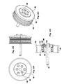
figures 1A à 1D , un mécanisme d'entraînement à poulie selon un premier mode de réalisation de l'invention, de face, de côté, en perspective et en coupe axiale ; - les
figures 2A à 2D , un mécanisme d'entraînement à poulie selon un deuxième mode de réalisation de l'invention, de face, de côté, en perspective et en coupe axiale ; - les
figures 3A à 3D , un mécanisme d'entraînement à poulie selon un troisième mode de réalisation de l'invention, de face, de côté, en perspective et en coupe axiale ; - les
figures 4A à 4D , un mécanisme d'entraînement à poulie selon un quatrième mode de réalisation de l'invention, de face, de côté, en perspective et en coupe axiale; - les
figures 5A à 5D , un sous-ensemble du mécanisme desfigures 4A à 4D , de face, de côté, en perspective et en coupe axiale.
- the
Figures 1A to 1D a pulley drive mechanism according to a first embodiment of the invention, from the front, from the side, in perspective and in axial section; - the
Figures 2A to 2D a pulley drive mechanism according to a second embodiment of the invention, from the front, from the side, in perspective and in axial section; - the
Figures 3A to 3D , a pulley drive mechanism according to a third embodiment of the invention, from the front, from the side, in perspective and in axial section; - the
Figures 4A to 4D , a pulley drive mechanism according to a fourth embodiment of the invention, from the front, from the side, in perspective and in axial section; - the
Figures 5A to 5D , a subset of the mechanism ofFigures 4A to 4D , from the front, from the side, in perspective and in axial section.
Pour alléger la présentation, les éléments communs aux différents modes de réalisation seront désignés par les mêmes signes de référence et leur description ne sera pas systématiquement répétée.To simplify the presentation, the elements common to the different embodiments will be designated by the same reference signs and their description will not be systematically repeated.
En référence aux
La bague extérieure 48, constituée d'une pièce en acier, est située tout entière du côté du plan de référence 34 opposé à la roue à aubes. La bague extérieure 48 délimite une ouverture dans laquelle est inséré le fût 16 et forme deux chemins de roulement extérieurs 54 situés en regard des chemins de roulement 24 de la bague intérieure 20. Ces chemins de roulement 24, 54 permettent de loger deux rangées de billes 56. Le roulement ainsi constitué est protégé de l'extérieur par deux joints d'étanchéité annulaires 60, montés sur la bague extérieure de part et d'autre des chemins de roulement 24, 54 et frottant sur la bague intérieure 20. Les lignes de charge des billes des deux rangées sont de préférence inclinées par rapport à un plan radial, et coupent l'axe de rotation en deux points situés dans deux plans radiaux qui encadrent les chemins de roulement.The
Un tambour de poulie 62 est fixé à la platine 40. Ce tambour comporte une bande de roulement 64 à profil radial en dents de scie. Il est en outre pourvu d'une coupelle 66 qui vient en appui sur la platine 40. La fixation est assurée par des goujons filetés axiaux 68 traversant des alésages 70, 71 prévus dans la platine et dans la coupelle. Les goujons 66 sont pourvus d'une tête reçue dans un chambrage de la platine et le serrage des pièces est obtenu grâce à des écrous 72, dont un a été représenté sur la
Le montage du mécanisme des
Sur les
Le montage du dispositif des
Sur les
Le procédé d'assemblage est ici simplifié puisque l'étape de montage de l'arbre sur les moyens de liaisons est éliminée.The assembly method is simplified here since the step of mounting the shaft on the connection means is eliminated.
Sur les
Le mode d'assemblage du mécanisme des
Naturellement, diverses modifications sont possibles.Naturally, various modifications are possible.
La bande de roulement peut avoir toute forme adaptée à une courroie d'entraînement, par exemple une forme tronconique ou à plusieurs troncs de cônes. Elle peut être le cas échéant pourvue de stries ou autres reliefs assurant une meilleure coopération avec la courroie. Le terme courroie utilisé dans l'ensemble de la demande doit être compris de manière générique comme incluant tout type de liaison souple sans fin, de section quelconque.The tread may have any shape suitable for a drive belt, for example a frustoconical shape or with several truncated cones. It may be optionally provided with ridges or other reliefs ensuring better cooperation with the belt. The term belt used throughout the application must be understood generically to include any type of endless flexible link, of any section.
L'invention n'est pas limitée à des pompes à eau, la roue à aubes pouvant être remplacée par tout type d'organe récepteur destiné à être solidarisé à une poulie entraînée par une courroie. La roue à aubes peut également être remplacée par un organe moteur entraînant l'arbre et le tambour de poulie, et destiné à entraîner la courroie.The invention is not limited to water pumps, the impeller may be replaced by any type of receiving member to be secured to a pulley driven by a belt. The impeller can also be replaced by a drive member driving the shaft and the pulley drum, and for driving the belt.
L'ordre des opérations d'assemblage peut être modifié suivant les besoins. Dans certaines circonstances, il peut être préférable de monter l'arbre sur le roulement avant le montage du roulement sur le bâti. Dans d'autres circonstances, ces opérations peuvent être inversées.The order of assembly operations can be changed as needed. In certain circumstances, it may be preferable to mount the shaft on the bearing before mounting the bearing to the frame. In other circumstances, these operations may be reversed.
Les moyens de liaison entre l'arbre et le tambour peuvent être de tout type assurant la transmission du couple, par exemple des rayons ou des bras. La fixation de ces moyens de liaison au tambour peut se faire par tout moyen, notamment par sertissage, emmanchement à chaud ou à froid, collage ou soudage. L'interface entre la bague extérieure et les moyens de liaison peut être lisse ou pourvue de reliefs, par exemple de cannelures.The connection means between the shaft and the drum can be of any type ensuring the transmission of torque, for example spokes or arms. Fixing these means of connection to the drum can be done by any means, including crimping, fitting hot or cold, gluing or welding. The interface between the outer ring and the connecting means may be smooth or provided with reliefs, for example flutings.
Les goujons peuvent être d'une seule pièce avec les moyens de liaison ou avec le tambour.The studs can be in one piece with the connecting means or with the drum.
L'homme du métier saura en outre combiner entre eux les divers mode de réalisation pour constituer d'autres variantes.Those skilled in the art will furthermore be able to combine the various embodiments with one another in order to constitute other variants.
Claims (15)
Applications Claiming Priority (1)
| Application Number | Priority Date | Filing Date | Title |
|---|---|---|---|
| FR0758554A FR2922974B1 (en) | 2007-10-24 | 2007-10-24 | BELT DRIVE MECHANISM AND METHOD FOR MANUFACTURING THE SAME. |
Publications (1)
| Publication Number | Publication Date |
|---|---|
| EP2053248A2 true EP2053248A2 (en) | 2009-04-29 |
Family
ID=39495670
Family Applications (1)
| Application Number | Title | Priority Date | Filing Date |
|---|---|---|---|
| EP20080291007 Withdrawn EP2053248A2 (en) | 2007-10-24 | 2008-10-24 | Belt drive mechanism and its manufacturing method |
Country Status (2)
| Country | Link |
|---|---|
| EP (1) | EP2053248A2 (en) |
| FR (1) | FR2922974B1 (en) |
Cited By (2)
| Publication number | Priority date | Publication date | Assignee | Title |
|---|---|---|---|---|
| FR2979395A1 (en) * | 2011-08-24 | 2013-03-01 | Skf Ab | Drive system for driving water pump, has revolving external ring and pulley rotatably connected to driving shaft, drive belt mounted on pulley, and support mounted on driving shaft and fixed at revolving ring |
| CN104895669A (en) * | 2015-05-30 | 2015-09-09 | 广西玉柴机器股份有限公司 | Multi-point axial additional belt wheel installation structure |
Families Citing this family (1)
| Publication number | Priority date | Publication date | Assignee | Title |
|---|---|---|---|---|
| DE102017109454B4 (en) * | 2017-05-03 | 2021-03-25 | Schaeffler Technologies AG & Co. KG | Drive unit of a coolant pump |
Citations (4)
| Publication number | Priority date | Publication date | Assignee | Title |
|---|---|---|---|---|
| FR2160201A5 (en) | 1971-11-11 | 1973-06-22 | Skf Ind Trading & Dev | |
| US3934966A (en) | 1971-11-11 | 1976-01-27 | Skf Industrial Trading And Development Company, B.V. | Cooling water pump, preferably of motor car engines |
| EP0289958A2 (en) | 1987-05-01 | 1988-11-09 | Koyo Seiko Co., Ltd. | Water pump |
| US6200089B1 (en) | 1998-03-26 | 2001-03-13 | Tcg Unitech Aktiengesellschaft | Coolant pump |
Family Cites Families (4)
| Publication number | Priority date | Publication date | Assignee | Title |
|---|---|---|---|---|
| DE4100507C1 (en) * | 1991-01-10 | 1992-05-14 | Mercedes-Benz Aktiengesellschaft, 7000 Stuttgart, De | Water pump leakage collector with chamber in belt pulley - which has arresting member on one rim bounding collecting chamber |
| US6960066B2 (en) * | 2002-02-21 | 2005-11-01 | Aisin Seiki Kabushiki Kaisha | Water pump with a hollow shaft, seal, and drain opening therein |
| JP2004162630A (en) * | 2002-11-14 | 2004-06-10 | Koyo Seiko Co Ltd | Rolling bearing unit for water pump |
| JP2006266187A (en) * | 2005-03-24 | 2006-10-05 | Aisin Seiki Co Ltd | Water pump and impeller device for water pump |
-
2007
- 2007-10-24 FR FR0758554A patent/FR2922974B1/en not_active Expired - Fee Related
-
2008
- 2008-10-24 EP EP20080291007 patent/EP2053248A2/en not_active Withdrawn
Patent Citations (4)
| Publication number | Priority date | Publication date | Assignee | Title |
|---|---|---|---|---|
| FR2160201A5 (en) | 1971-11-11 | 1973-06-22 | Skf Ind Trading & Dev | |
| US3934966A (en) | 1971-11-11 | 1976-01-27 | Skf Industrial Trading And Development Company, B.V. | Cooling water pump, preferably of motor car engines |
| EP0289958A2 (en) | 1987-05-01 | 1988-11-09 | Koyo Seiko Co., Ltd. | Water pump |
| US6200089B1 (en) | 1998-03-26 | 2001-03-13 | Tcg Unitech Aktiengesellschaft | Coolant pump |
Cited By (2)
| Publication number | Priority date | Publication date | Assignee | Title |
|---|---|---|---|---|
| FR2979395A1 (en) * | 2011-08-24 | 2013-03-01 | Skf Ab | Drive system for driving water pump, has revolving external ring and pulley rotatably connected to driving shaft, drive belt mounted on pulley, and support mounted on driving shaft and fixed at revolving ring |
| CN104895669A (en) * | 2015-05-30 | 2015-09-09 | 广西玉柴机器股份有限公司 | Multi-point axial additional belt wheel installation structure |
Also Published As
| Publication number | Publication date |
|---|---|
| FR2922974A1 (en) | 2009-05-01 |
| FR2922974B1 (en) | 2010-05-07 |
Similar Documents
| Publication | Publication Date | Title |
|---|---|---|
| EP1865206A2 (en) | Belt transmission mechanism | |
| FR2729440A1 (en) | ROLLING BEARING, IN PARTICULAR REAR BEARING OF A MOTOR VEHICLE ALTERNATOR | |
| WO2012052647A1 (en) | Brake drum, in particular for a motor vehicle, comprising an over-molding | |
| FR3052104A1 (en) | MOTOR VEHICLE WHEEL ASSEMBLY | |
| FR2644860A1 (en) | BEARING MOUNTING, ESPECIALLY FOR VEHICLE WHEELS | |
| EP2053248A2 (en) | Belt drive mechanism and its manufacturing method | |
| FR2908728A1 (en) | DEVICE FOR FASTENING THE WHEEL PIVOT OF A MOTOR VEHICLE. | |
| EP3325842B1 (en) | Assembly of a crankshaft end portion with a flywheel and a guide bearing, and related engine assembly | |
| WO2022161735A1 (en) | Wheel bearing equipped with a sealing device with gutter and chicane | |
| FR2779787A1 (en) | Compensating ring for especially bearing of motor vehicle steering column | |
| FR3068741B1 (en) | DRIVE SHAFT FOR A TURBOMACHINE | |
| FR3052103A1 (en) | MOTOR VEHICLE WHEEL ASSEMBLY | |
| EP4008929B1 (en) | Satellite assembly, epicyclic gearset provided with such an assembly and power transmission unit | |
| EP4204700B1 (en) | Sliding or rolling bearing equipped with a sealing device with a seal seat close to the axis of rotation | |
| EP2865538B1 (en) | Roller bearing with overmoulded flange | |
| EP0836685B1 (en) | Clutch release bearing mounting | |
| WO2021148676A1 (en) | Rotating assembly, in particular for guiding a motor vehicle wheel | |
| FR2668562A1 (en) | BEARING DEVICE, IN PARTICULAR FOR CARDAN JOINT. | |
| FR3112825A1 (en) | rotating assembly, in particular for guiding a motor vehicle wheel | |
| FR2869965A1 (en) | BEARING ASSEMBLY AND CORRESPONDING HOMOCINETIC SEAL | |
| EP4273391A1 (en) | Pre-assembly method for an aircraft turbine engine | |
| FR3106635A1 (en) | Automotive vehicle wheel assembly | |
| EP4055300A1 (en) | Roller gear element | |
| FR3018328A3 (en) | DIFFERENTIAL FOR MOTOR VEHICLE WITH HOLDING DEVICE IN THE POSITION OF THE AXLE SATELLITE | |
| FR3099219A1 (en) | Pulley device |
Legal Events
| Date | Code | Title | Description |
|---|---|---|---|
| PUAI | Public reference made under article 153(3) epc to a published international application that has entered the european phase |
Free format text: ORIGINAL CODE: 0009012 |
|
| AK | Designated contracting states |
Kind code of ref document: A2 Designated state(s): AT BE BG CH CY CZ DE DK EE ES FI FR GB GR HR HU IE IS IT LI LT LU LV MC MT NL NO PL PT RO SE SI SK TR |
|
| AX | Request for extension of the european patent |
Extension state: AL BA MK RS |
|
| STAA | Information on the status of an ep patent application or granted ep patent |
Free format text: STATUS: THE APPLICATION IS DEEMED TO BE WITHDRAWN |
|
| 18D | Application deemed to be withdrawn |
Effective date: 20140501 |