EP1589683A1 - Mehrträgerkommunikaitonssystem und empfangseinrichtung dafür - Google Patents
Mehrträgerkommunikaitonssystem und empfangseinrichtung dafür Download PDFInfo
- Publication number
- EP1589683A1 EP1589683A1 EP03815589A EP03815589A EP1589683A1 EP 1589683 A1 EP1589683 A1 EP 1589683A1 EP 03815589 A EP03815589 A EP 03815589A EP 03815589 A EP03815589 A EP 03815589A EP 1589683 A1 EP1589683 A1 EP 1589683A1
- Authority
- EP
- European Patent Office
- Prior art keywords
- sub
- channel
- soft decision
- channels
- receive
- Prior art date
- Legal status (The legal status is an assumption and is not a legal conclusion. Google has not performed a legal analysis and makes no representation as to the accuracy of the status listed.)
- Withdrawn
Links
Images


Classifications
-
- H—ELECTRICITY
- H04—ELECTRIC COMMUNICATION TECHNIQUE
- H04L—TRANSMISSION OF DIGITAL INFORMATION, e.g. TELEGRAPHIC COMMUNICATION
- H04L25/00—Baseband systems
- H04L25/02—Details ; arrangements for supplying electrical power along data transmission lines
- H04L25/03—Shaping networks in transmitter or receiver, e.g. adaptive shaping networks
- H04L25/03006—Arrangements for removing intersymbol interference
-
- H—ELECTRICITY
- H04—ELECTRIC COMMUNICATION TECHNIQUE
- H04L—TRANSMISSION OF DIGITAL INFORMATION, e.g. TELEGRAPHIC COMMUNICATION
- H04L25/00—Baseband systems
- H04L25/02—Details ; arrangements for supplying electrical power along data transmission lines
- H04L25/0202—Channel estimation
- H04L25/0204—Channel estimation of multiple channels
-
- H—ELECTRICITY
- H04—ELECTRIC COMMUNICATION TECHNIQUE
- H04L—TRANSMISSION OF DIGITAL INFORMATION, e.g. TELEGRAPHIC COMMUNICATION
- H04L25/00—Baseband systems
- H04L25/02—Details ; arrangements for supplying electrical power along data transmission lines
- H04L25/06—DC level restoring means; Bias distortion correction ; Decision circuits providing symbol by symbol detection
- H04L25/067—DC level restoring means; Bias distortion correction ; Decision circuits providing symbol by symbol detection providing soft decisions, i.e. decisions together with an estimate of reliability
-
- H—ELECTRICITY
- H04—ELECTRIC COMMUNICATION TECHNIQUE
- H04L—TRANSMISSION OF DIGITAL INFORMATION, e.g. TELEGRAPHIC COMMUNICATION
- H04L27/00—Modulated-carrier systems
- H04L27/26—Systems using multi-frequency codes
- H04L27/2601—Multicarrier modulation systems
- H04L27/2647—Arrangements specific to the receiver only
-
- H—ELECTRICITY
- H04—ELECTRIC COMMUNICATION TECHNIQUE
- H04L—TRANSMISSION OF DIGITAL INFORMATION, e.g. TELEGRAPHIC COMMUNICATION
- H04L5/00—Arrangements affording multiple use of the transmission path
- H04L5/02—Channels characterised by the type of signal
- H04L5/023—Multiplexing of multicarrier modulation signals, e.g. multi-user orthogonal frequency division multiple access [OFDMA]
- H04L5/026—Multiplexing of multicarrier modulation signals, e.g. multi-user orthogonal frequency division multiple access [OFDMA] using code division
-
- H—ELECTRICITY
- H04—ELECTRIC COMMUNICATION TECHNIQUE
- H04L—TRANSMISSION OF DIGITAL INFORMATION, e.g. TELEGRAPHIC COMMUNICATION
- H04L25/00—Baseband systems
- H04L25/02—Details ; arrangements for supplying electrical power along data transmission lines
- H04L25/03—Shaping networks in transmitter or receiver, e.g. adaptive shaping networks
- H04L25/03006—Arrangements for removing intersymbol interference
- H04L2025/0335—Arrangements for removing intersymbol interference characterised by the type of transmission
- H04L2025/03375—Passband transmission
- H04L2025/03414—Multicarrier
-
- H—ELECTRICITY
- H04—ELECTRIC COMMUNICATION TECHNIQUE
- H04L—TRANSMISSION OF DIGITAL INFORMATION, e.g. TELEGRAPHIC COMMUNICATION
- H04L25/00—Baseband systems
- H04L25/02—Details ; arrangements for supplying electrical power along data transmission lines
- H04L25/03—Shaping networks in transmitter or receiver, e.g. adaptive shaping networks
- H04L25/03006—Arrangements for removing intersymbol interference
- H04L2025/03433—Arrangements for removing intersymbol interference characterised by equaliser structure
- H04L2025/03439—Fixed structures
- H04L2025/03522—Frequency domain
-
- H—ELECTRICITY
- H04—ELECTRIC COMMUNICATION TECHNIQUE
- H04L—TRANSMISSION OF DIGITAL INFORMATION, e.g. TELEGRAPHIC COMMUNICATION
- H04L25/00—Baseband systems
- H04L25/02—Details ; arrangements for supplying electrical power along data transmission lines
- H04L25/0202—Channel estimation
- H04L25/0224—Channel estimation using sounding signals
- H04L25/0228—Channel estimation using sounding signals with direct estimation from sounding signals
- H04L25/023—Channel estimation using sounding signals with direct estimation from sounding signals with extension to other symbols
- H04L25/0232—Channel estimation using sounding signals with direct estimation from sounding signals with extension to other symbols by interpolation between sounding signals
Definitions
- the present invention relates to a multi-carrier communication system and a receiver thereof, and more particularly to a multi-carrier communication system using the interference between a target sub-channel and two or more upper and lower sub-channels (ICI) and a receiver thereof.
- ICI upper and lower sub-channels
- the bit error rate (BER) of the multi-carrier communication system in filter bank modulation, DMT modulation and FMT modulation can be improved by using receive signals that include distortion by inter-channel interference (ICI).
- Inter-channel interference occurs by the malfunction of a system in communication systems, such as OFDM - CDMA, or due to an unavoidable environment such as the loss of orthogonality between sub-channels.
- Inter-channel interference which is called the "leak of spectrum energy", at times the cross-talk between sub-channels, is caused by a leak.
- a major advantage of the turbo receiver of the present invention is that the phenomenon of ICI is handled as a zero mean Gaussian distribution random variable (e.g. Gaussian approximation used in the following document 1 below), for which a finite state discrete Markov process model is used. For such an ICI model, simple Gaussian approximation seems to be more practical because of the nature of ICI.
- the turbo receiver of the present invention is based on a maximum posterior probability estimation algorithm. In this turbo receiver, information derived from one sub-channel after non-linear processing refines the estimated maximum posterior probability of the latter channel, and in the same way, the information derived from the other sub-channel refines the estimated maximum probability of the former sub-channel.
- Document 1 K. Sathanathan and C. Tellambura: "Probability of error calculation of OFDM system with frequency offset", IEEE Trans. Commun., Vol. 49, NO. 11, Nov. 2001, pp. 1884 - 1888.
- the selection of a filter set in a multi-carrier communication system for filter bank modulation DMT (Discrete Multi-tone) modulation and FMT (Filtered Multi-tone) modulation, has been executed under the constraint that inter-symbol interference (ISI) and inter-channel interference (ICI) are completely removed.
- ISI inter-symbol interference
- ICI inter-channel interference
- the only method to relax such deterioration of BER is to minimize the frequency offset, and more particularly, to maintain it to be within 1% of the sub-carrier frequency interval.
- This method requires accurate frequency offset estimation, and also if the noise level is high when multi-carrier signals mixed with noise are received, the accuracy of frequency offset estimation is affected. Also according to this method, the Doppler shift is not consistent with respect to the transmission symbols in a high-speed fading channel, and operation becomes inaccurate in a high-speed fading channel which changes depending on the time.
- a target channel the first adjacent sub-channel located below the target sub-channel and the second adjacent sub-channel located above the target sub-channel, are considered.
- Fig. 1 and Fig. 2 show the frequency response of the three channels in the case when the frequency offset is zero (Fig. 1), and in the case when the frequency offset is not zero (Fig. 2).
- the signals of the central frequencies f 1 , f 2 and f 3 corresponding to the first, second and third sub-channels are indicated by the vertical arrows in Fig.
- the sub-channel number 0 (ch0) indicates the target sub-channel
- the sub-channel number -1 (ch-1) is a sub-channel located below the target sub-channel in the frequency scale
- the sub-channel number +1 (ch+1) indicates the sub-channel located above the target sub-channel in the frequency scale.
- the cycle of the DMT symbol is T
- the frequency scale is normalized with a channel interval equal to 1/T. In other words, one unit of the frequency scale is the channel interval.
- Fig. 1 shows, when the frequency offset (normalized by the channel interval) ⁇ is 0, the transfer function of the lower sub-channel and the upper sub-channel, indicated by the solid line A and the dotted line B in Fig.
- Fig. 2 shows the spectrum characteristics of each sub-channel of the DMT system when the frequency offset ⁇ is not zero.
- the spectrum of adjacent channels cross at -3dB, and the first side-lobe is -13dB, which is high.
- the case when the sub-channels which are distant for a 1 or 2 channel interval interfere with each other will be considered below. It is clear that the spectrum of an adjacent sub-channel has a mutual gain which is not zero, which is indicated as ⁇ 0-1 , ⁇ 1-1 , ⁇ 10 , ⁇ -10 , ⁇ 01 and ⁇ -11 .
- the first index of a indicates the interference source sub-channel
- the second index indicates the interference target sub-channel.
- ⁇ -10 indicates the leak transfer coefficient (amplitude) from the lower sub-channel with the sub-channel number -1 to the target channel with the sub-channel number 0.
- ⁇ -11 indicates the leak transfer coefficient (amplitude) from the lower sub-channel with the sub-channel number -1 to the upper sub-channel with the sub-channel number 1
- ⁇ 01 indicates the leak transfer coefficient from the target sub-channel with the sub-channel number 0 to the higher sub-channel with the sub-channel number 1
- ⁇ 0-1 indicates the leak transfer coefficient from the target sub-channel with the sub-channel number 0 to the lower sub-channel with the sub-channel number -1
- ⁇ 10 indicates the leak transfer coefficient from the higher sub-channel with the sub-channel number +1 to the target sub-channel with the sub-channel number 0.
- Fig. 3 is a general model (four sub-channel model) depicting the mutual ICI of four sub-channels in a DMT system having frequency offset.
- the four sub-channel model can improve the total system BER in more cases because of the low roll off spectrum characteristics of DMT.
- 1 1 , 1 2 , 1 3 and 1 4 are the transmitters of the sub-channels ch-1, ch0, ch+1 and ch+2, 2 1 , 2 2 , 2 3 and 2 4 are the receivers of each sub-channel, 3 1 , 3 2 , 3 3 and 3 4 are the transmission lines of each sub-channel.
- 4 ij is a multiplier to multiply the sub-channel signal D i by the leak transfer coefficient (interference coefficient) ⁇ ij of the sub-channel with the number i to the sub-channel with the number j respectively
- 5 1 , 5 2 , 5 3 and 5 4 are the first synthesizing units for synthesizing the cross-talk (ICI) from the adjacent sub-channel to its own sub-channel signal
- 6 1 , 6 2 , 6 3 and 6 4 are the second synthesizing units for synthesizing the cross-talk (ICI) from the sub-channel which is distant from two channel intervals to its own sub-channel signal
- 7 1 , 7 2 , 7 3 and 7 4 are the noise synthesizing units.
- the signals from the lower sub-channel ch-1 leak into the target sub-channel ch0 via the cross-talk coefficient ⁇ -10
- the signals from the upper sub-channel ch+1 leak into the target sub-channel via the cross-talk coefficient ⁇ 10
- the signals from the upper sub-channel ch+2 leak into the target sub-channel ch0 via the cross-talk coefficient ⁇ 20
- the signals from the lower sub-channel ch-2 leak into the target sub-channel via the cross-talk coefficient ⁇ -20 , but description thereof will be omitted since this can be regarded as the same as the leak from the ch+2.
- the sub-channels that cause mutual interference are limited to the upper and lower sub-channels, but the number of sub-channels in the entire communication system is not limited, so the model in Fig. 3 can also be applied to a multi-carrier communication system that has N number of sub-channels, where N is 4 or a greater number.
- interference to each sub-channel is only from the lower two sub-channels and the upper two sub-channels.
- the interference coefficient indicates a chain of coefficients.
- the noise components denoted as n 1 (t), n 2 (t), n 3 (t) and n 4 (t) in Fig. 3 are statistically independent (no correlation) because of the frequency orthogonality between the sub-channels.
- the sub-channels are located in the frequency domain, but this model can be applied not only to a DMT modulation type or a filter bank modulation type system, but also to other systems.
- the dimensions can be expanded to other domains, such as space (space division multiplex axis) and polarity.
- the model in Fig. 3 is beneficial in terms of understanding the physical process which causes ICI.
- the problem of this model lies in accurately deciding the receive signals of each sub-channel and the value of the transmission information symbols (a sign if a binary number).
- DFE decision feedback equalizer
- the present invention is a multi-carrier communication system for transmitting/receiving signals via at least four sub-channels, comprising a transmitter for transmitting data independently via four channels, a receiver comprising a receive unit disposed for each sub-channel for receiving data from a corresponding sub-channel and performing soft decision of the receive data, and means for inputting soft decision target values in the receive units corresponding to sub-channels other than a target sub-channel to a receive unit of the target sub-channel, wherein the receive unit of the target sub-channel adjusts its own soft decision target value using the soft decision target values that are input from the receive units of the other sub-channels, and decides the receive data based on the adjusted soft decision target value.
- the receive unit of the target sub-channel further comprises means for computing a difference between a probability that the data received from the target sub-channel is one value of a binary and a probability that the data is the other value of a binary as the soft decision target value, considering degree of coupling of cross-talk paths, means for adjusting the soft decision target value of the target sub-channel using the soft decision target values that are input from the receive units of the other sub-channels, and a decision unit for deciding the receive data based on adjusted the soft decision target value.
- Fig. 4 is a general block diagram depicting a communication system that demodulates receive data using the interference between a total of two sub-channels, lower and upper, and is a case when the number of sub-channels is three.
- the intent of the present invention is to provide a communication system having at least four sub-channels (four sub-channel model), but a communication system having three sub-channels (three sub-channel model) will be described first to assist in understanding the present invention.
- the communication system in Fig. 4 comprises three transmitters, 21, 22 and 23, for transmitting data independently via the three sub-channels, ch-1, ch0 and ch+1 respectively, many cross-talk paths 31 ij having a coupling coefficient ⁇ ij to the i-th to the j-th sub-channel, three receivers, 40, 50 and 60, which are installed for each sub-channel for receiving data from the corresponding sub-channel and performing the soft decision of the receive data, and means 71 and 72 for inputting the soft decision target value of each receiver to another receiver.
- 32 - 34 and 35 - 37 are synthesizing units for synthesizing ICI signals and noise.
- the receiver 50 of the sub-channel ch0 adjusts its own soft decision target value using the soft decision target values which were input from the receivers 40 and 60 of the lower and upper sub-channels ch-1 and ch+1, and decides "0" or "1" of the receive data based on the soft decision target value.
- the other respective receivers adjust its own soft decision target value using the soft decision target values which were input from the receivers of the lower and upper sub-channels, and decides "0" or "1” of the receiver data based on the soft bit decision target value.
- the value InD 0 to indicate the difference of the posterior possibility, is derived.
- the binary information is transmitted as the signal S* ij (t) via the two adjacent sub-channels.
- the time dependency of S* ij (t) in expressions is omitted.
- S* ij (t) is denoted as S* ij .
- the transmission information symbol D i is statistically independent (no correlation) and is an equally distributed probability variable.
- the signal of the target sub-channel affected by ICI from the lower and upper sub-channels is expressed as the linear coupling of the signals S* -1j and S* 1J transmitted by the upper and lower sub-channels and the target channel signal S* 0j by the cross-talk coefficient ⁇ .
- the index j of S j in the expressions (2) and (3) indicates the signal number, and is determined by pairing the symbols D -1 , D 1 and D 0 in the lower sub-channel, upper sub-channel and target sub-channel.
- the posterior probability to receive the signal S j that is the posterior probability P (S j /y (t)) of the receive signal becoming S j , is given by the following expression.
- P apr (S j ) is a prior probability of the receive signal S j
- P (y(t)/S j ) is a conditional probability, and is a probability where the transmitted sign signal is S j when the receive signal is y(t).
- D 0 +1
- P apr (S j ) is a prior probability (transmission probability) of the information signal S j with the number j in the target sub-channel being transmitted.
- Prior probability P apr (S* ij ) depends on the statistics of the data generation source, and in practical terms it is assumed to be equal to 1 ⁇ 2.
- Probability P (S* ij ) is the posterior probability of the receive signal S* ij , which is different from the prior probability P apr (S* ij ), and can be estimated at the receive side with high reliability, so P (S* ij ) ⁇ P (S* ij /y(t)).
- the decision information of the adjacent channels is used to decide the sign of the transmission information symbol D of a sub-channel.
- ln D -1 and ln D +1 indicate the logarithmic difference of the posterior probability of the information symbol in the lower sub-channel (ch-1) and the upper sub-channel (ch+1) becoming +1 and the posterior probability of that becoming -1. All calculations are in series, so when processing the data of the target sub-channel, the latest posterior probability from the adjacent channels can be used by repeat calculation.
- the algorithm is created such that InD 0 , which is the soft decision target value, is computed by the expressions (27) - (30), then "0" or "1" of the receive symbol of the target sub-channel is decided depending on the positive/negative of the soft decision target value InD 0 .
- Fig. 5 is a block diagram depicting a receiver of a three sub-channel model, that is, a receiver based on the maximum posterior probability using ICI (called a turbo receiver), and shows the configuration of only the receive unit of the target sub-channel, but the receive units of the other sub-channels also have the same configuration.
- This receive unit also has a configuration to execute the above mentioned algorithm.
- the receiver 50 of the target sub-channel further comprises a correlation unit (can be a match fill) 51, another channel decision result operating unit 52, first and second non-linear units 53 and 54, and symbol decision unit 55.
- a correlation unit can be a match fill
- another channel decision result operating unit 52 another channel decision result operating unit 52
- first and second non-linear units 53 and 54 second non-linear units 53 and 54
- symbol decision unit 55 symbol decision unit 55.
- the multiplier 51a and integrator 51b of the correlation unit 51 is a unit for computing of the decision expressions (28) - (30), the multiplier 51c and integrator 51d are units for computing the multiplier 51e and integrator 51f are units for computing and the multiplier 51g and integrator 51h are units for computing
- the addition unit 51i adds the integration output of the integrators 51b and 51d, subtractor 51j subtracts the integration outputs of the integrators 51b and 51d, the addition unit 51k adds the integration outputs of the integrators 51f and 51h, and the subtractor 51m subtracts the integration outputs of the integrators 51f and 51h.
- the addition unit 51n adds the outputs of the addition units 51i and 51k, and outputs the first term of the right side member of the expression (28), that is
- the subtraction unit 51 p subtracts the outputs of the addition units 51i and 51k, and outputs
- the division units 51q and 51r divide the input signal 1 ⁇ 2, and output the result.
- the other channel decision result operating unit 52 comprises the adders 52a - 52c, which compute the following respectively.
- the first non-linear unit 53 is a unit for computing ln cosh of the second - fifth terms of the right side member of the expression (28), and comprises the first and second non-linear sections 53a and 53b.
- the addition units 71a and 71b of the first non-linear section 53a compute the content of ⁇ ⁇ of the second and third terms of the right side member of the expression (28) respectively.
- the (E 0 - E 1 )/N 0 ⁇ E 1 .
- ln cosh computing units 71c and 71d compute the second and third terms of the right side member of the expression (28) respectively, and the subtractor 71e subtracts the computing result of the ln cosh computing unit 71d from the computing result of the ln cosh computing unit 71c.
- the addition units 71a' and 71b' of the second non-linear unit 53b compute the content of ⁇ ⁇ of the fourth and fifth terms of the right side member of the expression (28) respectively.
- the (E 2 - E 3 )/N 0 ⁇ E 2 ln cosh computing units 71c' and 71d' compute the fourth and fifth terms of the right side member of the expression (28) respectively, and the subtractor 71e' subtracts the computing result of the ln cosh computing unit 71d' from the computing result of the ln cosh computing unit 71c', and outputs the result.
- the addition unit 53c synthesizes the outputs of the adders 71e and 71e' and the division unit 53d divides the synthesized signal by 1 ⁇ 2, and outputs the computing results of the second - fifth terms of the expression (28).
- the second non-linear unit 54 is a unit for computing the first - third terms of the right side member of the expressions (29) and (30).
- the addition units 54a and 54b compute the first term of the right side member of the expressions (29) and (30) respectively
- the addition units 54c and 54d compute the second term and third term of the right side member of the expressions (29) and (30) respectively
- the addition units 54e and 54f compute the right side member of the expressions (29) and (30) respectively
- ln cosh computing units 54g and 54h compute ln cosh A - B / 2 and In cosh C - D / 2 respectively
- the subtraction unit 54i computes the difference between the outputs of the ln cosh computing units 54g and 54h, and outputs In cosh A - B 2 - ln cosh C - D 2 .
- the adder 55a of the symbol decision unit 55 adds the output signal of the division unit 51r of the correlation unit 51 and the output signal of the non-linear unit 53, and outputs A - B / 2 - C - D / 2, and the addition unit 55b generates the InD 0 (soft decision target value) of the expression (27).
- the decision unit 55c decides whether InD 0 is positive or negative, and decides that the receive symbol is "0" if positive, and that it is "1" if negative.
- the symbol decision unit 55 feeds back the computing result (soft decision target value) InD 0 of the expression (27) to the other channel decision result operating units of the receive units 40 and 60 of the lower and upper adjacent sub-channels.
- Fig. 6 is a general block diagram depicting a communication system for demodulating receive data using the interference between lower one sub-channel and upper two sub-channels, comprising four transmitters 121, 122, 123 and 124 for transmitting data independently via four sub-channels, ch-1, ch0, ch+1 and ch+2, many cross-talk paths 131 ij having the coupling coefficient ⁇ ij from the i-th sub-channel to the j-th sub-channel, four receivers 150, 160, 170 and 180 which are installed for each sub-channel for receiving data from the corresponding sub-channel and performing soft decision for the receive data, and means 191 and 192 for inputting the soft decision target value of each receiver to the receiver 160 of the target channel ch0.
- Means for inputting the other receivers is omitted in Fig. 6, but can be regarded as the same for the receiver 160.
- 132 - 139 and 140 - 143 are synthesizing units for synthesizing ICI signals and noises
- the receiver 160 of the sub-channel ch0 adjusts its own soft decision target value using the soft decision target values which were input from the receivers 150, 170 and 180 of the lower and upper sub-channels ch-1, ch+1 and ch+2, and decides "0" or "1" of the receive data based on the soft decision target value.
- the other receivers as well adjust their own soft decision target values using the soft decision target values which were input from the receivers of the lower and upper sub-channels, and decides "0" or "1" of the receive data based on the adjusted soft decision target values.
- the receive information of the target sub-channel can be decided as "0" if ln D 0 > 0, and the receive information of the target sub-channel is "1" if ln D 0 ⁇ 0.
- the signal of the target sub-channel affected by ICI from the lower and upper sub-channels is expressed as the linear coupling of the signals S* -1j , S* 1j and S* 2j transmitted by the upper and lower sub-channels, and the target channel signal S* 0j by the cross-talk coefficient ⁇ .
- the index j of S j in the expressions (32) and (33) indicates the signal number, and is determined by pairing the symbols D -1 , D 1 , D 2 and D 0 in the lower sub-channel, upper sub-channel and target sub-channel.
- ln D 0 a + b 2 - c + d 2 + ln cosh( a - b 2 ) - ln cosh( c - d 2 )
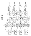
- Fig. 7 and Fig. 8 are block diagrams depicting a receiver of the target sub-channel of the present invention in the case when the cross-talk from upper two sub-channels and lower one sub-channel exist, which are separated in the figures by a dash and dotted line, and implements the computation of the right side member of the expression (41).
- Fig. 7 shows the configuration of the left side of the receiver
- Fig. 8 shows the right side thereof. If the receiver in Fig. 7 and Fig.
- this receiver 8 is the receiver of the target channel ch0, this receiver has a configuration combining the receiver of the three sub-channel model which receives cross-talk from the channels ch+1 and ch+2, and the receiver of the two sub-channel model which receives cross-talk from the channel ch1, and the expression (41) becomes the sum of the values at the points P1, P2 and P3 in Fig. 7 and Fig. 8.
- the receiver 160 of the target sub-channel comprises a correlation unit 161, first - third computing units 162 - 164, synthesizing unit 165 and decision unit 166.
- the first computing unit 162 has a configuration the same as the configuration enclosed by a dash and dotted line in Fig. 5, and computes the second - fifth terms of the right side member of the expression (28) and expressions (29) and (30) for the signals S 0 (t) ,... S 3 (t) out of the signals S 0 (t), S 1 (t),...S 7 (t).
- the second computing unit 163 has the same configuration as the configuration enclosed by the dash and dotted line in Fig. 5, and computes the second to fifth terms of the right side member of the expression (28) and the expressions (29) and (30) for the signals S 4 (t),...S 7 (t) out of the signals S 0 (t), S 1 (t), ... S 7 (t). However in the expressions (28), (29) and (30), S 0 (t) ... S 3 (t) are replaced with S 4 (t) ... S 7 (t).
- the synthesizing unit 165 synthesizes the computing result of the right side member of the expression (27) for the signals S 0 (t) ... S 3 (t), that is A + B 2 - C + D 2 + ln cosh( A - B 2 ) - ln cosh( C - D 2 ) and the computing result of the right side member of the expression (27) for the signals S 4 (t) ...
- the third computing unit 164 corrects the computing result based on the soft decision data ln D -1 of the lower sub-channel ch-1, and performs predetermined computation on the correction result, and inputs it to the synthesizing unit 165.
- the values of the first - fifth terms of the expression (28) for the signals S 0 (t), S 1 (t), S 2 (t) and S 3 (t) are expressed as 1 ⁇ - 5 ⁇
- the values of the first - fifth terms of the expression (28) for the signals S 4 (t), S 5 (t), S 6 (t) and S 7 (t) are expressed as 1 ⁇ ' - 5 ⁇ '
- the output of the soft decision data ln D -1 operating unit 164a is expressed as 6 ⁇
- the value of the point P2 becomes In cosh(1/2) • [ ⁇ ( 2 + 4 - 2 ' - 4 ' )/2 + 6 - ⁇ ⁇ ⁇ + In cosh ⁇ (A - B) /2 ⁇ -ln cosh ⁇ (A' -B')/2 ⁇ ]
- the value of the point P3 becomes ln cosh(1/2) • [ ⁇ ( 3 ' + 5 ' - 3 - 5 )/2 + 6 +
- the symbol decision unit 166 decides the positive/negative of the ln D 0 (soft decision target value), and if positive the receive symbol is decided as "0", and if negative it is decided as "1". Also the symbol decision unit 166 feeds back the ln D 0 (soft decision target value) to the decision result operating unit of the receive units 150, 170 and 180 of the lower and upper sub-channels.
- the receiver of the target sub-channel ch0 adjusts its own bit decision target value ln D 0 using the soft decision target values ln D +1 , ln D +2 and ln D -1 in the sub-channels other than the target sub-channel, and decides the receive data based on this soft decision target value.
- each decoder transfers the information to the other decoders, and refines the estimated posterior probability sequentially using the information derived by the other decoders.
- the information derived from one sub-channel is used to refine the estimated posterior probability of the other channel after non-linear processing, and the information derived from the latter sub-channel is used to refine the estimated posterior probability of the former channel.
- an individual decoder output is hard bit decision (hard decision) format in the turbo decoder, sharing information has few advantages.
- a hard bit decision is similar to the decision feedback equalizer proposed by Viterbo and Fazel in the above mentioned Document 2 for canceling ICI.
- the hard bit decision is executed only at the end of a repeat.
- ln D -1 , ln D 1 and ln D 2 acquired in the previous step are applied to the decision expressions (35) - (36) and (41) to compute the new estimate value of the posterior probability of the target sub-channel.
- the output of one sub-channel receiver is used as the prior probability for the other receivers.
- (A) is QPSK modulated original data
- (B) are signals deteriorated by ICI
- (D) is the receive data after one repeat according to the present invention
- (E) is the constellation of the receive data after the second repeat according to the present invention.
- the dispersion in constellation is small, and the BER is improved to become smaller. As the number of repeats increases, the dispersion in constellation decreases further, and BER is further improved.
- Eb/N 0 is a ratio of the average receive signal energy Eb against the background noise power spectrum intensity N 0 per bit.
- a DMT base communication system As an application of the turbo receiver of the present invention, a DMT base communication system is considered.
- Fig. 11 is a block diagram depicting the DMT base communication system using this turbo receiver, and has a configuration where the turbo receiver of the present invention is disposed in the subsequent stage of the FFT section of the receiver in a known DMT communication system.
- the input beam stream with data rate R (bits/sec: bps) is transferred at the new rate R/N (bps) after the serial-parallel converter (S/P) 201 through N number of parallel sub-channels.
- the N point IFFT 202 combines the N parallel data and converts it into one set of real-time domain sample signals.
- P/S parallel-serial converter
- these N samples are converted into a serial format, and are continuously input into the digital-analog converter (DAC) 204.
- the output signal of the low pass filter (LPF) 205 at the DAC output side is the duration DMT signal.
- the transmission DMT signal is deteriorated by the white Gaussian noise n(t) and is sent to the DMT receiver 300.
- the receiver executes a function the opposite of the transmitter.
- the FFT 301 performs demodulation processing for the signals sent via each sub-channel as N matched filter arrays.
- the turbo 302 1 - 302 N perform sub-channel processing based on the turbo algorithm of the present invention, and by this, BER improves even if a frequency offset exists.
- 303 is the AD converter
- 304 is the serial-parallel converter
- 305 is the parallel-serial converter.
- Fig. 12 shows the BER performance of a conventional DMT base receiver and the BER performance of a DMT receiver which has the turbo processing function of the present invention, and performs three times and six times of turbo repeats.
- N 64
- the BER performance is shown for 2Eb/N 0 using a frequency offset normalized by an inter-channel frequency as a parameter, and "proposed" is indicated by the BER characteristic B and B' (ICI - four model) of the present invention.
- the BER characteristic improves as the frequency offset becomes smaller, and the BER characteristic is better in the "ICI - four model" of the present invention than the conventional device.
- the BER characteristic improves for 2dB.
- the present invention is a receiver based on an estimated posterior probability
- a receiver of each sub-channel is a turbo receiver for transferring information to the receivers of the adjacent sub-channels, and refines the estimated posterior probability using the information derived by the receivers of the adjacent sub-channels repeatedly. Therefore the turbo receiver of the present invention can improve BER performance considerably compared with a conventional matched filter receiver.
- the non-linear signal processing of the turbo algorithm of the present invention uses the information acquired by the adjacent sub-channels so as to maximize the posterior probability.
- the biggest improvement in BER is generated in a high S/N ratio area where ICI dominates Gaussian noise.
- the turbo receiver of the present invention can achieve good performance throughout a considerably wide rage of ICI coupling coefficients.
Landscapes
- Engineering & Computer Science (AREA)
- Signal Processing (AREA)
- Computer Networks & Wireless Communication (AREA)
- Power Engineering (AREA)
- Mobile Radio Communication Systems (AREA)
- Digital Transmission Methods That Use Modulated Carrier Waves (AREA)
- Radio Transmission System (AREA)
- Noise Elimination (AREA)
Applications Claiming Priority (1)
| Application Number | Priority Date | Filing Date | Title |
|---|---|---|---|
| PCT/JP2003/000950 WO2004068756A1 (ja) | 2003-01-31 | 2003-01-31 | マルチキャリア通信システム及びその受信装置 |
Publications (2)
| Publication Number | Publication Date |
|---|---|
| EP1589683A1 true EP1589683A1 (de) | 2005-10-26 |
| EP1589683A4 EP1589683A4 (de) | 2009-04-08 |
Family
ID=32800833
Family Applications (1)
| Application Number | Title | Priority Date | Filing Date |
|---|---|---|---|
| EP03815589A Withdrawn EP1589683A4 (de) | 2003-01-31 | 2003-01-31 | Mehrträgerkommunikaitonssystem und empfangseinrichtung dafür |
Country Status (4)
| Country | Link |
|---|---|
| US (1) | US7317761B2 (de) |
| EP (1) | EP1589683A4 (de) |
| JP (1) | JP3934651B2 (de) |
| WO (1) | WO2004068756A1 (de) |
Families Citing this family (15)
| Publication number | Priority date | Publication date | Assignee | Title |
|---|---|---|---|---|
| US7627056B1 (en) * | 2002-03-29 | 2009-12-01 | Scientific Research Corporation | System and method for orthogonally multiplexed signal transmission and reception on a non-contiguous spectral basis |
| JP3892871B2 (ja) | 2003-03-05 | 2007-03-14 | 富士通株式会社 | 通信システムにおける受信装置 |
| JP4516478B2 (ja) * | 2005-05-20 | 2010-08-04 | 富士通株式会社 | M−ary−QAMMIMO通信システムのための受信装置 |
| JP4887758B2 (ja) * | 2005-11-28 | 2012-02-29 | 富士通株式会社 | 無線受信装置 |
| JP5145766B2 (ja) * | 2007-05-21 | 2013-02-20 | 株式会社Jvcケンウッド | 軟判定装置及び軟判定方法 |
| US7885028B2 (en) * | 2008-04-08 | 2011-02-08 | Samsung Electronics Co., Ltd. | Data error recovery using voting on multiple retrials |
| US8982971B2 (en) | 2012-03-29 | 2015-03-17 | QRC, Inc. | System for spectrum sensing of multi-carrier signals with equidistant sub-carriers |
| US8976906B2 (en) | 2012-03-29 | 2015-03-10 | QRC, Inc. | Method for spectrum sensing of multi-carrier signals with equidistant sub-carriers |
| US9348608B2 (en) | 2013-04-24 | 2016-05-24 | QRC, Inc. | System and method for registering application and application transforms on a radiofrequency digitization and collection device |
| US11605166B2 (en) | 2019-10-16 | 2023-03-14 | Parsons Corporation | GPU accelerated image segmentation |
| US11303306B2 (en) | 2020-01-20 | 2022-04-12 | Parsons Corporation | Narrowband IQ extraction and storage |
| US11619700B2 (en) | 2020-04-07 | 2023-04-04 | Parsons Corporation | Retrospective interferometry direction finding |
| US11569848B2 (en) | 2020-04-17 | 2023-01-31 | Parsons Corporation | Software-defined radio linking systems |
| US11575407B2 (en) | 2020-04-27 | 2023-02-07 | Parsons Corporation | Narrowband IQ signal obfuscation |
| US11849347B2 (en) | 2021-01-05 | 2023-12-19 | Parsons Corporation | Time axis correlation of pulsed electromagnetic transmissions |
Family Cites Families (7)
| Publication number | Priority date | Publication date | Assignee | Title |
|---|---|---|---|---|
| JPH10178458A (ja) | 1996-12-17 | 1998-06-30 | Kokusai Electric Co Ltd | 復調回路 |
| US6317470B1 (en) * | 1998-09-15 | 2001-11-13 | Ibiquity Digital Corporation | Adaptive weighting method for orthogonal frequency division multiplexed soft symbols using channel state information estimates |
| WO2001026264A1 (fr) * | 1999-09-30 | 2001-04-12 | Fujitsu Limited | Emetteur, recepteur et procede d'emission dans un systeme d'emission a ondes porteuses multiples |
| US6879640B1 (en) * | 1999-10-20 | 2005-04-12 | Broadcom Corporation | Method, apparatus and system for high-speed transmission on fiber optic channel |
| JP2001211088A (ja) * | 2000-01-27 | 2001-08-03 | Seiko Epson Corp | データ誤り訂正方法及び装置 |
| JP4342674B2 (ja) * | 2000-01-28 | 2009-10-14 | 三菱電機株式会社 | 通信装置 |
| US6973134B1 (en) * | 2000-05-04 | 2005-12-06 | Cisco Technology, Inc. | OFDM interference cancellation based on training symbol interference |
-
2003
- 2003-01-31 EP EP03815589A patent/EP1589683A4/de not_active Withdrawn
- 2003-01-31 WO PCT/JP2003/000950 patent/WO2004068756A1/ja not_active Ceased
- 2003-01-31 JP JP2004567542A patent/JP3934651B2/ja not_active Expired - Lifetime
-
2005
- 2005-03-23 US US11/086,416 patent/US7317761B2/en not_active Expired - Lifetime
Non-Patent Citations (2)
| Title |
|---|
| See also references of WO2004068756A1 * |
| TOELTSCH M ET AL: "Equalization of OFDM-systems by interference cancellation techniques" ICC 2001. 2001 IEEE INTERNATIONAL CONFERENCE ON COMMUNICATIONS. CONFERENCE RECORD. HELSINKY, FINLAND, JUNE 11 - 14, 2001; [IEEE INTERNATIONAL CONFERENCE ON COMMUNICATIONS], NEW YORK, NY : IEEE, US, vol. 6, 11 June 2001 (2001-06-11), pages 1950-1954, XP010553206 ISBN: 978-0-7803-7097-5 * |
Also Published As
| Publication number | Publication date |
|---|---|
| US7317761B2 (en) | 2008-01-08 |
| JPWO2004068756A1 (ja) | 2006-05-25 |
| EP1589683A4 (de) | 2009-04-08 |
| US20050163241A1 (en) | 2005-07-28 |
| JP3934651B2 (ja) | 2007-06-20 |
| WO2004068756A1 (ja) | 2004-08-12 |
Similar Documents
| Publication | Publication Date | Title |
|---|---|---|
| EP1589683A1 (de) | Mehrträgerkommunikaitonssystem und empfangseinrichtung dafür | |
| CN102246479B (zh) | 带有ici噪声估计的接收机 | |
| US6654340B1 (en) | Differential OFDM using multiple receiver antennas | |
| EP1335518A1 (de) | Empfang Mehrträger-Spreizspekturmsignale | |
| CN112953653A (zh) | 一种单载波多用户水声通信方法 | |
| US7505524B2 (en) | Receiver device and communication system | |
| US7274744B2 (en) | Multicarrier communication system and reception device for same | |
| CN119010945B (zh) | 一种适用于城市信道的多径分集接收扩频通信系统 | |
| EP1536581B1 (de) | System und Vorrichtung unter Verwendung weicher Entscheidungen in einem Mehrträgerübertragungssystem | |
| US10411934B2 (en) | Superposition coded orthogonal frequency division multiplexing (SC-OFDM) system | |
| CN117397215A (zh) | 基于码本线性化的预编码信号的生成和接收 | |
| Makka et al. | Reduction of inter-symbol interference using artifical neural network system in multicarrier OFDM system | |
| Sharma et al. | Channel estimation and equalization using FIM for MIMO-OFDM on doubly selective faded noisy channels | |
| JP3892871B2 (ja) | 通信システムにおける受信装置 | |
| CN101322365A (zh) | 多载波系统中的噪声功率插值 | |
| JP3930511B2 (ja) | 受信装置及び通信システム | |
| JP4091076B2 (ja) | 通信システムにおける受信装置 | |
| Upadhyay et al. | A novel technique Spanding for optical f-OFDM system | |
| KR20060072096A (ko) | 선형 등화기를 사용하는 직교 주파수 분할 다중화 통신시스템에서 엘엘알 산출 방법 및 그 장치 | |
| Arthi | Performance Analysis of Multi Carrier CDMA Transceiver System using a Novel Dynamic Decoding and Scheduling Procedure | |
| CN121126402A (zh) | 一种基于深度神经网络的信号收发处理方法及系统 | |
| CN120342818A (zh) | 一种面向otfs系统的信号检测方法 | |
| Duwarah et al. | Multi Carrier Symbol Recovery in OFDM using ANN in Wireless Channel | |
| Nigam | Mitigation of ICI in OFDM and Its Techniques | |
| Hole et al. | Adaptive coded modulation for wireless OFDM channels: Upper bounds on average spectral efficiency and influence of imperfect channel knowledge |
Legal Events
| Date | Code | Title | Description |
|---|---|---|---|
| PUAI | Public reference made under article 153(3) epc to a published international application that has entered the european phase |
Free format text: ORIGINAL CODE: 0009012 |
|
| 17P | Request for examination filed |
Effective date: 20050322 |
|
| AK | Designated contracting states |
Kind code of ref document: A1 Designated state(s): AT BE BG CH CY CZ DE DK EE ES FI FR GB GR HU IE IT LI LU MC NL PT SE SI SK TR |
|
| RBV | Designated contracting states (corrected) |
Designated state(s): DE FR GB |
|
| A4 | Supplementary search report drawn up and despatched |
Effective date: 20090305 |
|
| 17Q | First examination report despatched |
Effective date: 20110118 |
|
| STAA | Information on the status of an ep patent application or granted ep patent |
Free format text: STATUS: THE APPLICATION IS DEEMED TO BE WITHDRAWN |
|
| 18D | Application deemed to be withdrawn |
Effective date: 20120801 |