EP1589552A1 - Tastschalter - Google Patents
Tastschalter Download PDFInfo
- Publication number
- EP1589552A1 EP1589552A1 EP05103167A EP05103167A EP1589552A1 EP 1589552 A1 EP1589552 A1 EP 1589552A1 EP 05103167 A EP05103167 A EP 05103167A EP 05103167 A EP05103167 A EP 05103167A EP 1589552 A1 EP1589552 A1 EP 1589552A1
- Authority
- EP
- European Patent Office
- Prior art keywords
- movable contact
- contact
- switch
- recess
- contacts
- Prior art date
- Legal status (The legal status is an assumption and is not a legal conclusion. Google has not performed a legal analysis and makes no representation as to the accuracy of the status listed.)
- Granted
Links
Images
Classifications
-
- H—ELECTRICITY
- H01—ELECTRIC ELEMENTS
- H01H—ELECTRIC SWITCHES; RELAYS; SELECTORS; EMERGENCY PROTECTIVE DEVICES
- H01H13/00—Switches having rectilinearly-movable operating part or parts adapted for pushing or pulling in one direction only, e.g. push-button switch
- H01H13/02—Details
- H01H13/26—Snap-action arrangements depending upon deformation of elastic members
- H01H13/48—Snap-action arrangements depending upon deformation of elastic members using buckling of disc springs
-
- H—ELECTRICITY
- H01—ELECTRIC ELEMENTS
- H01H—ELECTRIC SWITCHES; RELAYS; SELECTORS; EMERGENCY PROTECTIVE DEVICES
- H01H13/00—Switches having rectilinearly-movable operating part or parts adapted for pushing or pulling in one direction only, e.g. push-button switch
- H01H13/50—Switches having rectilinearly-movable operating part or parts adapted for pushing or pulling in one direction only, e.g. push-button switch having a single operating member
- H01H13/64—Switches having rectilinearly-movable operating part or parts adapted for pushing or pulling in one direction only, e.g. push-button switch having a single operating member wherein the switch has more than two electrically distinguishable positions, e.g. multi-position push-button switches
-
- H—ELECTRICITY
- H01—ELECTRIC ELEMENTS
- H01H—ELECTRIC SWITCHES; RELAYS; SELECTORS; EMERGENCY PROTECTIVE DEVICES
- H01H2205/00—Movable contacts
- H01H2205/016—Separate bridge contact
- H01H2205/024—Means to facilitate positioning
- H01H2205/026—Adhesive sheet
Definitions
- the present invention relates to a push-on switch in which a dome-like movable contact is inverted as a result of a depressing operation to make electrical conduction, and more particularly to a two-step push-on switch into which two or upper and lower movable contacts are incorporated.
- the proposed switch comprises: a housing having an accommodating portion; a central stationary contact which is disposed on an inner bottom face of the accommodating portion of the housing; a first peripheral stationary contact which is disposed outside the central stationary contact; a second peripheral stationary contact which is disposed outside the first peripheral stationary contact; a dome-like lower movable contact in which a central area of an inflated portion is opposed to the central stationary contact, and a peripheral edge portion is always in contact with the first peripheral stationary contact; and a dome-like upper movable contact which has a diameter larger than the external shape of the lower movable contact, and in which a central area of an inflated portion is opposed to the lower movable contact so as to cover the lower movable contact, and a peripheral edge portion is always in contact with the second peripheral stationary contact.
- a plurality of arms are crosswise elongated from the upper movable contact so as to be continuous to the invertible inflated portion.
- accommodating recesses in which the arms of the upper movable contact are respectively accommodated in a bendable and stretchable manner are formed so as to be continuous to the accommodating portion.
- the second peripheral stationary contact which is always in contact with at least one of the arms is placed in the accommodating recesses.
- a problem which is to be solved by the invention is as follows.
- the dimensions of the switch particularly the width must be reduced.
- a dome-like cross plate spring is used as an upper movable contact as described above, a square accommodating space is required, and hence size reduction of the width of a switch is limited from the viewpoint of a shape.
- the invention is characterized in that, in a two-step push-on switch in which dome-like movable contacts are placed in two or upper and lower stages in an invertible manner in a recess of an insulative body having a plurality of stationary contacts, the upper movable contact is formed into an oval shape.
- the movable contacts are fixed in an invertible manner to the body respectively by adhesive sheets each of which is bonded from a side of an upper face of corresponding one of the movable contacts, a through hole is formed in a central area of the adhesive sheet which fixes the lower movable contact to the body, a downward projection is disposed in a central area of the upper movable contact, and an upper face of a top portion of the lower movable contact is exposed through the through hole of the adhesive sheet, thereby enabling the upper face to be contacted with the projection of the upper movable contact.
- a configuration having: a central stationary contact which is disposed in a central area of a bottom face of the recess to be opposed to the top portion of the lower movable contact; a first peripheral stationary contact which is disposed outside the central stationary contact, and which is always in contact with an outer peripheral edge portion of the lower movable contact; and a second peripheral stationary contact which is disposed outside the first peripheral stationary contact, and which is always in contact with an outer peripheral edge portion of the upper movable contact that is larger than the lower movable contact.
- the invention is characterized also in that, in the upper movable contact, legs are elongated continuously from four corners of an oval portion which is invertible, leg accommodating recesses which accommodate the legs of the upper movable contact are formed in four corners of the body to be continuous to the recess, respectively, and a stationary contact which is always in contact with at least one of the legs is disposed in the leg accommodating recesses.
- the legs elongate from the four corners of the invertible oval portion to be continuous in a longitudinal direction of the oval portion.
- the upper movable contact is formed into an oval dome-like shape which is obtained by cutting away both ends of a circular dome-like movable contact in the conventional art. Therefore, it is possible to obtain a two-step push-on switch in which reduction of the dimensions of the switch, particularly the width can be realized while ensuring the operation stroke of the movable contact, and which has a reduced width that enables the switch to be mounted even in a side face of a thin apparatus such as a portable telephone.
- the upper movable contact having an oval dome-like shape even when the central area is largely displaced as a result of depression, a stress produced in the movable contact is more relaxed as compared with that applied to a circular dome-like movable contact in the conventional art.
- the invention can provide a two-step push-on switch which can attain effects such as that occurrence of failures such as cracks or deflection is suppressed, that the life number of ON/OFF operations is remarkably increased, and that the life period is longer than that of a conventional switch.
- the through hole is formed in the central area of the adhesive sheet which fixes the lower movable contact to the body, the downward projection is disposed in the central area of the upper movable contact, and the upper face of the top portion of the lower movable contact is exposed through the through hole of the adhesive sheet, thereby enabling the upper face to be contacted with the projection of the upper movable contact, the upper movable contact and the lower movable contact can be directly contacted with each other so as to attain electrical conduction, although the lower movable contact is simply bonded and fixed to the body by the adhesive sheet.
- the downward projection disposed in the central area of the upper movable contact plays the role of a support member which, in the conventional art, is disposed as another member in a central area between upper and lower movable contacts in order to definitely obtain senses of two-step operations. Therefore, it is possible to obtain excellent senses without increasing the number of parts. Consequently, this configuration is effective.
- the body has: the central stationary contact which is disposed in the central area of the bottom face of the recess to be opposed to the top portion of the lower movable contact; the first peripheral stationary contact which is disposed outside the central stationary contact, and which is always in contact with the outer peripheral edge portion of the lower movable contact; and the second peripheral stationary contact which is disposed outside the first peripheral stationary contact, and which is always in contact with the outer peripheral edge portion of the upper movable contact that is larger than the lower movable contact, it is possible to obtain a two-step push-on switch in which the upper movable contact is first inverted by a depressing operation, so that the downward projection disposed in the central area of the upper movable contact is in contact with the lower movable contact, whereby the second peripheral stationary contact and the first peripheral stationary contact are electrically connected to each other to obtain an operation sense and electrical conduction of the first step, or the first-step switch enters an ON state while producing an operation sense, and the lower movable contact is then inverted to be in contact
- the legs are elongated continuously from four corners of the oval portion which is invertible, the leg accommodating recesses which accommodate the legs of the upper movable contact are formed in four corners of the body to be continuous to the recess, respectively, and the stationary contact which is always in contact with at least one of the legs is disposed in the leg accommodating recesses, the legs are provided with a spring property, thereby enabling the movable contact to be always in electric contact with the stationary contact (the second peripheral stationary contact) in both a no-load condition (both the first- and second-step switches are turned OFF) and a case where a load causing a large displacement amount is applied (the second-step switch is turned ON).
- the stationary contact is grounded, a sure countermeasure against static electricity can be performed, and hence the invention is effective.
- a two-step push-on switch structure was realized in which the operation sense can be improved while improving the durability of the upper movable contact and reducing the number of parts, and the width of the switch is reduced while ensuring the operation stroke of the movable contact.
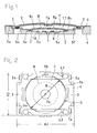
- Fig. 1 is a section view of a push-on switch of the first embodiment
- Fig. 2 is a plan view showing a state where an upper adhesive sheet in the switch shown in Fig. 1 is removed away
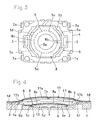
- Fig. 3 is a plan view showing a state where an upper movable contact in the switch shown in Fig. 2 is removed away.
- the push-on switch of the embodiment will be schematically described.
- two dome-like movable contacts 6, 7 having different sizes and shapes are placed in two or upper and lower stages in a recess 5 of a body 4 having a plurality of stationary contacts 1, 2, 3, and the movable contacts 6, 7 are fixed in an invertible manner to the body 4 respectively by adhesive sheets 8, 9 each of which is bonded from the side of the upper face of corresponding one of the movable contacts, thereby configuring a two-step push-on switch.
- the body 4 is made of an insulating material such as a synthetic resin, and formed into a shallow box-like structure (tray-like structure) which has an internally formed recess 5, which has a substantially rectangular external shape, and in which the upper face is opened.
- the recess 5 of the body 4 is configured by: an upper recess 5a which is formed by recessing the upper face of the body 4 by one step into an substantially oval shape while not recessing the outer peripheral edge portion; a middle recess 5b which is formed by recessing the bottom face of the upper recess 5a by one step into an substantially oval shape while not recessing both end portions of the bottom face in the longitudinal direction of the body 4; and a lower recess 5c which is formed by recessing the bottom face of the middle recess 5b by one step into a circular shape while not recessing the outer peripheral edge portion.
- the recesses 5a, 5b, 5c are located concentric with the center of the body 4.
- the upper and middle recesses 5a, 5b having an substantially oval shape are formed in the body 4 so that their both arcuate end portions are opposed to one set of short sides which are opposed to each other in the longitudinal direction of the body 4, and their both linear side edges are parallel to the long sides which are opposed to each other in the lateral direction of the body 4.
- a recess middle bottom face 5d (the bottom face of the lower recess 5c) which is horizontal and circular is formed at the middle of the deepest portion of the recess 5.
- a first recess peripheral bottom face 5e (the outer peripheral edge portion of the bottom face of the middle recess 5b) which is horizontal and substantially annular is formed at a position which is in the periphery of the recess middle bottom face 5d, and which is higher in level by one step than the recess middle bottom face.
- a second recess peripheral bottom face 5f (both end portions of the bottom face of the upper recess 5a in the longitudinal direction of the body 4) which is horizontal and arcuate is formed at two positions which are in both outer sides of the first recess peripheral bottom face 5e in the longitudinal direction of the body 4, opposed to each other across the middle recess 5b in the longitudinal direction of the body 4, and higher in level by one step than the first recess peripheral bottom face 5e.
- the stationary contacts 1, 2, 3 provided on the body 4 are made of a metal material which is electrically conductive, and attached integrally to the body 4 by insert molding or the like during a process of molding the body 4.
- the stationary contacts are configured respectively as: a middle stationary contact 1 which is disposed in a middle portion of the recess middle bottom face 5d serving as the bottom face middle portion of the recess 5, in a state where one end portion is exposed; first peripheral stationary contacts 2 which are disposed at symmetric positions of the outer peripheral edge portion of the recess middle bottom face 5d serving as two positions which are outside the middle stationary contact 1 and opposed to each other across the middle stationary contact in the lateral direction of the body 4, in a state where one end portion is exposed; and second peripheral stationary contacts 3 which are disposed on the center line of the second recess peripheral bottom face 5f in the longitudinal direction of the body 4, and at two positions which are outside the first peripheral stationary contacts 2 and opposed to each other across the middle recess 5b in the longitudinal direction of the body 4, in a state where one end portion is
- the lower movable contact 6 is configured by a metal plate spring which is electrically conductive, and formed into a dome-like shape which is circular, which has a diameter that is slightly smaller than that of the lower recess 5c, and which is upward inflatingly curved.
- the lower movable contact 6 is formed so that the center top portion is higher than the depth of the lower recess 5c, and lower than the total depth of the lower recess 5c and the middle recess 5b.
- the upper movable contact 7 is configured in the same manner as the lower movable contact 6 by a metal plate spring which is electrically conductive, but formed into a dome-like shape which has a size that enables the upper movable contact to cover the lower movable contact 6 from the upper side, which is oval unlike the lower movable contact 6, and which is upward inflatingly curved. More specifically, the upper movable contact 7 is configured in the following manner.
- the upper movable contact has a diameter R which is larger at least than the diameter of the lower movable contact 6, and smaller than the width A1 of the longitudinal side of the body 4 (in the embodiment, the upper movable contact having a diameter R which is larger than the diameter of the lower movable contact 6, and smaller than the width A2 of the lateral side of the body 4 is shown).
- the upper movable contact is formed into an oval shape in which edge portions of a dome-like disc 70 (see the phantom lines in Fig.
- the upper movable contact is formed so as to be placeable in the upper recess 5a of the body 4 in a direction (posture) in which, in a plan view, the linear cut edges of the upper movable contact 7 elongate along the one set of longitudinal sides opposed in the lateral direction of the body 4, and the arcuate uncut edges are opposed to the one set of lateral sides opposed in the longitudinal direction of the body 4.
- the upper movable contact 7 is formed so that the center top portion is higher than the depth of the upper recess 5a, and a circular projection 7a which downward projects is formed integrally in a central area of the upper movable contact 7.
- the lower adhesive sheet 8 which fixes the lower movable contact 6 to the body 4 in an invertible manner is obtained by forming an adhesive layer on one face of a resin-made sheet which is flexible, elastic, and insulative, and formed into a C-like shape.
- the adhesive sheet 8 is an adhesive sheet in which a circular through hole 8a having a diameter that is smaller than that of the lower movable contact 6 and larger than the projection 7a of the upper movable contact 7 is concentrically formed in a central area of a circular adhesive sheet having a diameter enabling the sheet to cover the lower movable contact 6 and the outer peripheral edge portion to be bonded to the first recess peripheral bottom face 5e of the body 4, and one thin cutaway 8b which extends from the outer peripheral edge to reach the through hole 8a is radially formed in a part of the circular annular portion of the adhesive sheet that is annularly formed, whereby the adhesive sheet is formed into a non-annular or C-like shape.
- the adhesive sheet has the through hole 8a in the central area, and a C-like non-annular portion 8c in which the portion surrounding the through hole 8a is interrupted by the cutaway 8b.
- the non-annular portion 8c is bonded to both the outer peripheral edge portion of the lower movable contact 6 and an inner peripheral edge portion of the first recess peripheral bottom face 5e of the body 4 surrounding the outer peripheral edge portion.
- the circumferential bonding range is not the whole peripheries of the outer peripheral edge portion of the lower movable contact 6 and the inner peripheral edge portion of the first recess peripheral bottom face 5e of the body 4 surrounding the outer peripheral edge portion, but is positively interrupted by the cutaway 8b.
- the upper adhesive sheet 9 which fixes the upper movable contact 7 to the body 4 in an invertible manner is obtained by forming an adhesive layer on one face of a resin-made sheet which is flexible, elastic, and insulative.
- the upper adhesive sheet 9 is formed into a substantially rectangular shape having a size enabling the sheet to cover the upper movable contact 7, and an outer peripheral edge portion to be bonded to an outer peripheral edge portion of the upper face of the body 4 which remains in the periphery of the upper recess 5a.
- the lower movable contact 6 having a circular dome-like shape is fitted in an upward inflated posture into the circular lower recess 5c which is the deepest portion of the recess 5 of the body 4, to be placed above the recess middle bottom face 5d.
- the adhesive sheet 8 having a C-like shape is bonded from the side of the upper face of the lower movable contact 6 to the upper face of the outer peripheral edge portion and the inner peripheral edge portion of the first recess peripheral bottom face 5e of the body 4 surrounding the outer peripheral edge portion so that the non-annular portion 8c extends over the upper face of the outer peripheral edge portion of the lower movable contact 6 and the inner peripheral edge portion of the first recess peripheral bottom face 5e of the body 4 surrounding the outer peripheral edge portion, thereby causing the lower movable contact 6 to be fixed to the bottom portion of the recess 5 of the body 4 by the lower adhesive sheet 8 in an invertible manner.
- the upper movable contact 7 having an oval dome-like shape is fitted in an upward inflated posture into the substantially oval upper recess 5a serving as an upper opening (the shallowest portion) of the recess 5 of the body 4, to be placed above the second recess peripheral bottom face 5f.
- the upper adhesive sheet 9 having a substantially rectangular shape is bonded from the side of the upper face of the upper movable contact 7 to the upper face and the upper face outer peripheral edge portion of the body 4 surrounding the upper face so as to integrally cover the upper movable contact 7 and the upper face outer peripheral edge portion of the body 4 surrounding the upper movable contact to close the recess 5, thereby causing the upper movable contact 7 to be fixed to the upper opening of the recess 5 of the body 4 by the upper adhesive sheet 9 in an invertible manner.
- the two-step push-on switch is assembled in a state where the two or upper and lower movable contacts 6, 7 are accommodated and concentrically placed in two or upper and lower stages in the recess 5 of the body 4 with forming a predetermined gap, the top of the central area of the lower movable contact 6 is separated and opposed above the middle stationary contact 1 of the body 4, the outer peripheral edge portion of the lower movable contact 6 is always in contact with the first peripheral stationary contacts 2 of the body 4, the downward projection 7a of the central area of the upper movable contact 7 is separated and opposed above the central area of the lower movable contact 6, and the arcuate uncut edges of the upper movable contact 7 are always in contact with the second peripheral stationary contacts 3 of the body 4.
- the lower adhesive sheet 8 which fixes the lower movable contact 6 to the body 4 in an invertible manner is formed into a C-like shape, the upper face of the top portion of the central area of the lower movable contact 6 is exposed through the through hole 8a of the lower adhesive sheet 8, and the downward projection 7a of the central area of the upper movable contact 7 is separated from and opposed to the exposed portion.
- the top of the central area of the lower movable contact 6 and the downward projection 7a of the central area of the upper movable contact 7 can be directly contacted with each other.
- the opening is closed by the upper adhesive sheet 9.
- the recess is formed as a sealed space, so that dusts which may cause a contact failure in contacts is prevented from entering, and the sealed spaced is partitioned into two or upper and lower layers by the lower adhesive sheet 8 and the lower movable contact 6. Since the lower adhesive sheet 8 which fixes the lower movable contact 6 to the body 4 in an invertible manner is formed into a C-like shape, the small space below the lower adhesive sheet 8 and the lower movable contact 6, i.e., a space 10 between the recess middle bottom face 5d of the body 4 and the lower movable contact 6 communicates with a large space above the lower adhesive sheet 8 and the lower movable contact 6, i.e., a space 11 between the lower movable contact 6 and the upper movable contact 7, through the cutaway 8b by which the lower adhesive sheet 8 is formed into a non-annular shape.
- a body which accommodates a circular dome-like movable contact having a diameter of R must be formed into a square shape having sides of A1.
- the width of the body 4 in the lateral direction of the upper movable contact 7 can be made smaller than the width of the upper movable contact 7 in the longitudinal direction (A1 > A2), while ensuring the same operation stroke as a circular dome-like movable contact having a diameter of R. In the assembled two-step push-on switch, therefore, the dimension in the width direction can be reduced.
- the two-step push-on switch which is assembled as described above is surface-mounted in a state where the external contacts 1a, 2a, 3a protruding from the body 4 are electrically connected by soldering to contacts formed on a circuit board of an apparatus such as an electronic apparatus or communication apparatus, to be mounted on the apparatus. Since the dimensions, particularly the width are reduced, the switch can be mounted even in a side face of a thin apparatus such as a portable telephone.
- the operation of the push-on switch of the embodiment will be described.
- the upper movable contact 7 is returned to an upward inflated dome-like shape as shown in Fig. 1, and the arcuate uncut edges are in contact with the second peripheral stationary contacts 3 to attain electrical conduction.
- the downward projection 7a in the central area is separated from the lower movable contact 6.
- the lower movable contact 6 is returned to an upward inflated dome-like shape, and the outer peripheral edge portion is in contact with the first peripheral stationary contacts 2 to attain electrical conduction.
- the top of the central area is separated from the middle stationary contact 1. Therefore, both the two or upper and lower step switches are in the OFF state.
- the center area of the upper movable contact 7 is downward depressed from the side above the upper adhesive sheet 9 by an operating member such as a key top.
- the upper movable contact 7 is rapidly inverted to a downward inflated state, and the lower face of the downward projection 7a of the central area is directly contacted with the upper face of the top portion of the central area of the lower movable contact 6 which is exposed through the through hole 8a of the lower adhesive sheet 8, so that the upper movable contact 7 and the lower movable contact 6 are electrically connected to each other.
- the second peripheral stationary contacts 3 and the first peripheral stationary contacts 2 are connected to each other through the upper and lower movable contacts 7 and 6 which are in the electrically conductive state, thereby causing the first-step (upper) switch to enter the ON state with producing an operation sense.
- the lower movable contact 6 When the center area of the lower movable contact 6 cannot withstand the depressing force, the lower movable contact 6 is rapidly inverted to a downward inflated state, and the lower face of the center area makes contact with the middle stationary contact 1, and the first peripheral stationary contacts 2 and the middle stationary contact 1 are connected to each other through the lower movable contact 6, thereby causing the second-step (lower) switch to enter the ON state with producing an operation sense.
- the second-step switch When, in the two-step push-on switch, the second-step switch is transferred from the OFF state to the ON state in succession to the first-step switch, or when the central area of the lower movable contact 6 is inverted from the upward inflated dome-like shape to the downward inflated shape, the lower space 10 between the recess middle bottom face 5d of the body 4 and the lower movable contact 6 is reduced so that the pressure of the lower space 10 tries to be raised higher than the atmospheric pressure. However, the lower space 10 communicates with the upper space 11 between the lower movable contact 6 and the upper movable contact 7, through the cutaway 8b by which the lower adhesive sheet 8 is formed into a non-annular shape.
- the air in the lower space 10 escapes to the upper space 11, and hence the pressure of the lower space 10 is hardly raised higher than the atmospheric pressure.
- the second-step switch is transferred from the ON state to the OFF state, or when the central area of the lower movable contact 6 is returned from the downward inflated shape to the initial shape or the upward inflated dome-like shape, the air in the upper space 11 is sucked into the lower space 10 in accordance with the expansion of the lower space 10, and hence the pressure of the lower space 10 is not reduced lower than the atmospheric pressure.
- the air flows into and from the lower space 10 are enabled so as to maintain the pressure of the lower space 10 to the atmospheric pressure, whereby the operation characteristics of the lower movable contact 6 can be sufficiently exerted so that an excellent operation sense can be obtained when the lower movable contact 6 operates.
- the deformation shape (displacement amount) when the first-step switch of the two-step push-on switch is transferred from the ON state to the OFF state, or when the central area of the upper movable contact 7 is inverted from the upward inflated dome-like shape to the downward inflated shape is smaller than the deformation shape (displacement amount) when the second-step switch of the two-step push-on switch is transferred from the OFF state to the ON state, or when the central area of the lower movable contact 6 is inverted from the upward inflated dome-like shape to the downward inflated shape.
- the difference in deformation shape (displacement amount) between the upper movable contact 7 and the lower movable contact 6 can produce a difference between the operation sense of the first-step switch and that of the second-step switch, whereby senses of two-step operations can be definitely obtained.
- the projection 7a which is used for definitely obtaining senses of two-step operations is not disposed as a separate member dedicated to this purpose, but is formed integrally with the central area of the upper movable contact 7. Therefore, the number of parts is not increased.
- the upper movable contact 7 is formed into an oval shape in which edge portions of the circular dome-like disc 70 (see the phantom lines in Fig. 2) are cut away by the two parallel lines L1, L2. Even in the case where, when a depressing operation is applied so as to cause the second-step switch to be turned ON, the central area of the upper movable contact 7 is largely displaced, therefore, a stress produced in the upper movable contact 7 is relaxed (as compared with the case of a circular dome-like movable contact), whereby failures such as cracks or deflection (creep) are prevented from occurring and the life number of ON/OFF operations is remarkably increased.
- the two-step push-on switch of the embodiment has a structure in which the dome-like movable contacts 6, 7 are placed in two or upper and lower stages in the recess 5 of the insulative body 4 having the plural contacts 1, 2, 3, and the movable contacts 6, 7 are fixed in an invertible manner to the body 4 by the adhesive sheets 8, 9 that are bonded respectively to the movable contacts from the upper face side, and comprises air releasing means (the cutaway 8b) for enabling the space 10 between the inner bottom face (the recess middle bottom face 5d) of the body 4 and the lower movable contact 6 to communicate with the space 11 between the lower movable contact 6 and the upper movable contact 7.
- the air releasing means may be a cutaway or an air hole which passes through the lower movable contact 6.
- the means is the cutaway 8b disposed in the outer peripheral edge portion of the adhesive sheet 8 for fixing the lower movable contact 6 to the body 4, the operation characteristics of the lower movable contact 6, and the electrical conduction property based on the contact with the upper movable contact 7 are not impaired.
- the through hole 8a is disposed in the central area of the adhesive sheet 8 for fixing the lower movable contact 6 to the body 4, the upper face of the top portion of the lower movable contact 6 is exposed through the through hole 8a so as to be contactable with the upper movable contact 7, the cutaway 8b which extends from the outer peripheral edge of the adhesive sheet 8 to reach the through hole 8a is disposed, and the cutaway 8b which forms the adhesive sheet 8 into a non-annular shape is used as the air releasing means.
- the lower movable contact 6 is simply bonded and fixed to the body 4 by the adhesive sheet 8, therefore, the upper movable contact 7 and the lower movable contact 6 can be directly contacted with each other to attain electrical conduction. Moreover, the operation characteristics of the lower movable contact 6 are not impaired, and an excellent sense can be obtained.
- the upper movable contact 7 is formed into an oval shape. Since the upper movable contact 7 is formed into an oval dome-like shape which is obtained by cutting away both ends of the circular dome-like disc 70, reduction of the width of the switch is particularly realized while ensuring the operation stroke of the upper movable contact 7. Therefore, it is possible to obtain a two-step push-on switch having a reduced width which enables the switch to be mounted even in a side face of a thin apparatus such as a portable telephone.
- the movable contacts 6, 7 are fixed in an invertible manner to the body 4 by the adhesive sheets 8, 9 that are bonded respectively to the movable contacts from the upper face side, the through hole 8a is disposed in the central area of the adhesive sheet 8 for fixing the lower movable contact 6 to the body 4, the downward projection 7a is disposed in the central area of the upper movable contact 7, and the upper face of the top portion of the lower movable contact 6 is exposed through the through hole 8a of the adhesive sheet 8 to be enabled to be in contact with the projection 7a of the upper movable contact 7, whereby the upper movable contact 7 and the lower movable contact 6 can be directly contacted with each other to attain electrical conduction although the lower movable contact 6 is simply bonded and fixed to the body 4 by the adhesive sheet 8.
- the downward projection 7a disposed in the central area of the upper movable contact 7 plays the role of a support member which, in the conventional art, is disposed as another member in a central area between the upper and lower movable contacts 6, 7 in order to definitely obtain senses of two-step operations. Therefore, it is possible to obtain excellent senses without increasing the number of parts.
- the two-step push-on switch of the embodiment has a structure in which the dome-like movable contacts 6, 7 are placed in an invertible manner in two or upper and lower stages in the recess 5 of the insulative body 4.
- the central stationary contact 1 which is disposed in the central area of the bottom face (the recess middle bottom face 5d) of the body 4 to be opposed to the top of the lower movable contact 6
- the first peripheral stationary contacts 2 which are disposed outside the central stationary contact 1, and which are always in contact with the outer peripheral edge portion of the lower movable contact 6
- the second peripheral stationary contacts 3 which are disposed outside the first peripheral stationary contacts 2, and which are always in contact with the outer peripheral edge portion of the upper movable contact 7 that is larger than the lower movable contact 6.
- the upper movable contact 7 is first inverted by a depressing operation to be in contact with the lower movable contact 6, whereby the second peripheral stationary contacts 3 and the first peripheral stationary contacts 2 are electrically connected to each other to obtain an operation sense and electrical conduction of the first step, or the first-step switch enters the ON state while producing an operation sense.
- the lower movable contact 6 is inverted to be in contact with the central stationary contact 1, whereby the first peripheral stationary contacts 2 and the central stationary contact 1 are electrically connected to each other to obtain an operation sense and electrical conduction of the second step, or the second-step switch enters the ON state while producing an excellent operation sense.
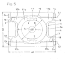
- Fig. 4 is a section view of a push-on switch of the second embodiment
- Fig. 5 is a plan view of the switch showing a state where an upper adhesive sheet shown in Fig. 4 is removed away.
- the components identical with those of the push-on switch of the first embodiment are denoted by the same reference numerals, and their description is omitted.
- an upper movable contact 17 is different from the upper movable contact 7 of the push-on switch of the first embodiment.
- the movable contact 17 of the push-on switch of the second embodiment is configured by continuously elongating legs 17b from four corners of the invertible upper movable contact 7 of the push-on switch of the first embodiment.
- the upper movable contact is configured by: an invertible oval portion 17a which is a body of the upper movable contact that, in the same manner as the upper movable contact 7 of the push-on switch of the first embodiment, has an oval shape and is formed into an upward inflatingly curved dome-like shape; and the four legs 17b which elongate from the four corners of the oval portion 17a to be continuous in the longitudinal direction.
- leg accommodating recesses 18 in which the legs 17b of the upper movable contact 17 are respectively accommodated in a bendable and stretchable manner are formed so as to be continuous to the recess 5 of the body 4, in accordance with the upper movable contact 17.
- the leg accommodating recesses 18 are projectingly formed from the four corners of the upper recess 5a of the body 4 so as to be continuous in the longitudinal direction.
- the upper movable contact 17 having the legs 17b in the four corners is fitted into the upper recess 5a having the leg accommodating recesses 18 in the four corners, to be accommodated in the upper recess 5a in a state where the tip ends of the legs 17b are butted against and supported by the bottom faces of the leg accommodating recesses 18 which are continuous to the four corners of the second recess peripheral bottom face 5f, and fixed in an invertible manner to the upper opening (the upper recess 5a) of the recess 5 of the body 4 by the upper adhesive sheet 9.
- stationary contacts which are always in contact with at least one of the legs 17b i.e., the second peripheral stationary contacts 3 are disposed in the leg accommodating recesses 18.
- the second peripheral stationary contacts 3 are respectively disposed in the bottom surfaces of the leg accommodating recesses 18 in which two legs 17b positioned on a diagonal line of the upper movable contact 17 are respectively accommodated, in a state where one end portion is exposed, and the upper movable contact 17 is always in contact with the second peripheral stationary contacts 3 via two legs 17b.
- the external contact 3a for the second peripheral stationary contacts 3 is connected by soldering to a grounding conductor of the circuit board, so that the upper movable contact 17 is always grounded through the second peripheral stationary contacts 3.
- the legs 17b are elongated in the upper movable contact 17 continuously from the four corners of the oval portion 17a which is invertible
- the leg accommodating recesses 18 which accommodate the legs 17b of the upper movable contact 17 are formed in four corners of the body 4 to be continuous to the recess 5, respectively
- the stationary contacts 3 which are always in contact with at least one of the legs 17b are disposed in the leg accommodating recesses 18,
- the legs 17b are provided with a spring property, whereby the contact following property (contact performance) of the contact portions (the legs 17b) with respect to the stationary contacts 3 when the upper movable contact 17 is inverted or returned is improved, and momentary interruption can be prevented from occurring, so that the upper movable contact 17 is always in electric contact with the stationary contacts (the second peripheral stationary contacts) 3 in both a no-load condition (both the first- and second-step switches are turned OFF) and a case where a load causing a large displacement amount is applied (the
- the two legs 17b which are on a diagonal line of the upper movable contact 17 are caused to be in contact with the stationary contacts 3. Even when a peripheral portion which is deviated from the central area of the upper movable contact 17 is depressed, therefore, contact is attained in at least one set of the leg 17b and the stationary contact 3. Therefore, the embodiment is effective in realizing more ensured conductance.
Landscapes
- Push-Button Switches (AREA)
- Switches With Compound Operations (AREA)
- Eye Examination Apparatus (AREA)
Applications Claiming Priority (4)
| Application Number | Priority Date | Filing Date | Title |
|---|---|---|---|
| JP2004125521 | 2004-04-21 | ||
| JP2004125521 | 2004-04-21 | ||
| JP2004331467 | 2004-11-16 | ||
| JP2004331467A JP4445837B2 (ja) | 2004-04-21 | 2004-11-16 | プッシュオンスイッチ |
Publications (2)
| Publication Number | Publication Date |
|---|---|
| EP1589552A1 true EP1589552A1 (de) | 2005-10-26 |
| EP1589552B1 EP1589552B1 (de) | 2007-07-25 |
Family
ID=34939400
Family Applications (1)
| Application Number | Title | Priority Date | Filing Date |
|---|---|---|---|
| EP05103167A Expired - Lifetime EP1589552B1 (de) | 2004-04-21 | 2005-04-20 | Tastschalter |
Country Status (5)
| Country | Link |
|---|---|
| US (1) | US6995324B2 (de) |
| EP (1) | EP1589552B1 (de) |
| JP (1) | JP4445837B2 (de) |
| AT (1) | ATE368290T1 (de) |
| DE (1) | DE602005001718T2 (de) |
Cited By (4)
| Publication number | Priority date | Publication date | Assignee | Title |
|---|---|---|---|---|
| EP2209131A1 (de) * | 2009-01-14 | 2010-07-21 | Sick Ag | Gerät mit wenigstens einem Bedienelement |
| EP2463882A1 (de) * | 2010-12-10 | 2012-06-13 | Thales | Gesicherter kompakter Doppelkontakt-Druckknopfschalter |
| US20140110237A1 (en) * | 2012-10-18 | 2014-04-24 | Panasonic Corporation | Push switch |
| CN105261506A (zh) * | 2014-07-14 | 2016-01-20 | 富士康(昆山)电脑接插件有限公司 | 按压式开关 |
Families Citing this family (36)
| Publication number | Priority date | Publication date | Assignee | Title |
|---|---|---|---|---|
| TWI236690B (en) * | 2002-09-11 | 2005-07-21 | Fujikura Ltd | Membrane for key switch and the key switch |
| JP2005039037A (ja) * | 2003-07-14 | 2005-02-10 | Tanaka Kikinzoku Kogyo Kk | 摺動子 |
| FR2859567B1 (fr) * | 2003-09-09 | 2006-04-14 | Itt Mfg Enterprises Inc | Dispositif de commutation electrique a actionnement lateral |
| US7252444B2 (en) * | 2004-04-08 | 2007-08-07 | Research In Motion Limited | Switch configuration |
| US20080164133A1 (en) * | 2004-06-15 | 2008-07-10 | Japan Aviation Electronice Industry Limited | Dome-Shaped Contact and Multi-Step Operation Electrical Switch Incorporating the Same |
| JP4503424B2 (ja) * | 2004-11-30 | 2010-07-14 | アルプス電気株式会社 | 多段スイッチ装置 |
| JP4371987B2 (ja) * | 2004-12-07 | 2009-11-25 | ホシデン株式会社 | プッシュオンスイッチ |
| USD533144S1 (en) * | 2005-02-18 | 2006-12-05 | Hosiden Corporation | Push-button switch |
| JP2006286582A (ja) * | 2005-04-05 | 2006-10-19 | Alps Electric Co Ltd | スイッチ装置 |
| JP4729991B2 (ja) * | 2005-06-13 | 2011-07-20 | パナソニック株式会社 | 電子機器 |
| USD537797S1 (en) * | 2005-08-30 | 2007-03-06 | Matsushita Electric Industrial Co., Ltd. | Switch |
| US7402764B2 (en) * | 2006-03-22 | 2008-07-22 | Nokia Corporation | Multi-functional touch actuator in electronic devices |
| JP4703489B2 (ja) * | 2006-05-31 | 2011-06-15 | 株式会社東芝 | メンブレンスイッチ、キーボードおよびキーボードを有する電子機器 |
| JP4802930B2 (ja) * | 2006-08-10 | 2011-10-26 | パナソニック株式会社 | プッシュスイッチ |
| US7493810B2 (en) * | 2006-08-18 | 2009-02-24 | Rensselaer Polytechnic Institute | Device for mechanical weight bearing indication with load range capability |
| TWD121829S1 (zh) * | 2006-10-11 | 2008-03-11 | 星電股份有限公司 | 開關 |
| US7217893B1 (en) * | 2006-10-13 | 2007-05-15 | Altek Corporation | Two-stage button structure |
| JP4788576B2 (ja) * | 2006-11-09 | 2011-10-05 | パナソニック株式会社 | 可動接点 |
| US20080237008A1 (en) * | 2007-03-26 | 2008-10-02 | Ming-Han Lin | Dust-proof switch |
| EP2179456B1 (de) * | 2007-06-21 | 2015-09-23 | Mason Electric Co. | Hall effekt-system |
| JP4894671B2 (ja) * | 2007-08-07 | 2012-03-14 | パナソニック株式会社 | 可動接点 |
| US7557320B1 (en) * | 2008-07-30 | 2009-07-07 | Apple Inc. | Surface-mount dome switch |
| USD598870S1 (en) * | 2008-09-02 | 2009-08-25 | Hosiden Corporation | Push-button switch |
| EP2175463B1 (de) | 2008-10-08 | 2013-04-24 | Research In Motion Limited | Zweistufen-Schalteranordnung |
| EP2184752B1 (de) * | 2008-10-08 | 2011-02-02 | Research In Motion Limited | Zweistufiger Einzeltaster |
| US20100224473A1 (en) * | 2009-03-03 | 2010-09-09 | Coactive Technologies, Inc. | Multi-function switch structure |
| USD627745S1 (en) | 2009-07-30 | 2010-11-23 | Hosiden Corporation | Switch |
| USD639749S1 (en) | 2009-07-30 | 2011-06-14 | Hosiden Corporation | Switch |
| JP5555547B2 (ja) * | 2010-05-31 | 2014-07-23 | ホシデン株式会社 | キースイッチ |
| TWD154407S1 (zh) * | 2011-04-26 | 2013-07-01 | Smk股份有限公司 | 開關 |
| TWD156201S (zh) * | 2011-11-14 | 2013-10-01 | Smk股份有限公司 | 開關 |
| JP1521450S (de) * | 2013-03-26 | 2018-04-02 | ||
| JP1487382S (de) * | 2013-03-26 | 2016-12-19 | ||
| GB2524041A (en) * | 2014-03-12 | 2015-09-16 | Nordic Semiconductor Asa | Frequency synthesizer |
| JP6896097B2 (ja) * | 2017-11-20 | 2021-06-30 | シチズン電子株式会社 | スイッチ用可動接点体及びスイッチ |
| TWI792753B (zh) * | 2021-12-09 | 2023-02-11 | 群光電子股份有限公司 | 按鍵結構 |
Citations (4)
| Publication number | Priority date | Publication date | Assignee | Title |
|---|---|---|---|---|
| WO2000073886A1 (fr) * | 1999-05-26 | 2000-12-07 | Zhuoqin Chen | Clavier ergonomique conçu pour un fonctionnement avec une seule main |
| EP1162521A1 (de) * | 2000-06-07 | 2001-12-12 | Eta SA Fabriques d'Ebauches | Betätigungsvorrichtung mit Schnappeffekt und mit solcher Vorrichtung ausgerüstete Uhr |
| JP2003007168A (ja) * | 2001-06-21 | 2003-01-10 | Alps Electric Co Ltd | 押釦スイッチ |
| EP1524679A1 (de) * | 2003-10-16 | 2005-04-20 | Hosiden Corporation | Beweglicher Kontakt für einen Tastschalter und Tastschalter |
Family Cites Families (8)
| Publication number | Priority date | Publication date | Assignee | Title |
|---|---|---|---|---|
| US4659881A (en) * | 1986-01-27 | 1987-04-21 | Eastman Kodak Company | Multidome multistage switch assembly |
| US4933522A (en) * | 1989-03-07 | 1990-06-12 | Itt Corporation | Flanged snap dome |
| US5898147A (en) * | 1997-10-29 | 1999-04-27 | C & K Components, Inc. | Dual tact switch assembly |
| DE19946020A1 (de) * | 1999-09-25 | 2001-03-29 | Eaton Corp | Wippenschalter für jeweils einen zweistufigen Betätigungshub |
| FR2799570B1 (fr) | 1999-10-08 | 2001-11-16 | Itt Mfg Enterprises Inc | Commutateur electrique perfectionne a effet tactile a plusieurs voies et a organe de declenchement unique |
| US6262383B1 (en) * | 2000-02-25 | 2001-07-17 | Sagami Electric Company, Ltd. | Tact switch and its movable contact piece |
| JP2003187671A (ja) * | 2001-12-14 | 2003-07-04 | Nec Saitama Ltd | キー入力回路、及び、携帯端末の入力装置 |
| JP4180877B2 (ja) * | 2002-10-22 | 2008-11-12 | Smk株式会社 | 2段動作プッシュスイッチ |
-
2004
- 2004-11-16 JP JP2004331467A patent/JP4445837B2/ja not_active Expired - Lifetime
-
2005
- 2005-04-12 US US11/103,543 patent/US6995324B2/en not_active Expired - Lifetime
- 2005-04-20 EP EP05103167A patent/EP1589552B1/de not_active Expired - Lifetime
- 2005-04-20 DE DE602005001718T patent/DE602005001718T2/de not_active Expired - Lifetime
- 2005-04-20 AT AT05103167T patent/ATE368290T1/de not_active IP Right Cessation
Patent Citations (4)
| Publication number | Priority date | Publication date | Assignee | Title |
|---|---|---|---|---|
| WO2000073886A1 (fr) * | 1999-05-26 | 2000-12-07 | Zhuoqin Chen | Clavier ergonomique conçu pour un fonctionnement avec une seule main |
| EP1162521A1 (de) * | 2000-06-07 | 2001-12-12 | Eta SA Fabriques d'Ebauches | Betätigungsvorrichtung mit Schnappeffekt und mit solcher Vorrichtung ausgerüstete Uhr |
| JP2003007168A (ja) * | 2001-06-21 | 2003-01-10 | Alps Electric Co Ltd | 押釦スイッチ |
| EP1524679A1 (de) * | 2003-10-16 | 2005-04-20 | Hosiden Corporation | Beweglicher Kontakt für einen Tastschalter und Tastschalter |
Non-Patent Citations (1)
| Title |
|---|
| PATENT ABSTRACTS OF JAPAN vol. 2003, no. 05 12 May 2003 (2003-05-12) * |
Cited By (10)
| Publication number | Priority date | Publication date | Assignee | Title |
|---|---|---|---|---|
| EP2209131A1 (de) * | 2009-01-14 | 2010-07-21 | Sick Ag | Gerät mit wenigstens einem Bedienelement |
| US8604375B2 (en) | 2009-01-14 | 2013-12-10 | Sick Ag | Device with at least one control element |
| EP2463882A1 (de) * | 2010-12-10 | 2012-06-13 | Thales | Gesicherter kompakter Doppelkontakt-Druckknopfschalter |
| FR2968826A1 (fr) * | 2010-12-10 | 2012-06-15 | Thales Sa | Commutateur a poussoir securise compact a double dome |
| CN102543534A (zh) * | 2010-12-10 | 2012-07-04 | 泰勒斯公司 | 紧凑型双触头安全按钮开关 |
| US8735747B2 (en) | 2010-12-10 | 2014-05-27 | Thales | Compact double-contact secured pushbutton switch |
| CN102543534B (zh) * | 2010-12-10 | 2017-03-01 | 泰勒斯公司 | 紧凑型双触头安全按钮开关 |
| US20140110237A1 (en) * | 2012-10-18 | 2014-04-24 | Panasonic Corporation | Push switch |
| CN105261506A (zh) * | 2014-07-14 | 2016-01-20 | 富士康(昆山)电脑接插件有限公司 | 按压式开关 |
| CN105261506B (zh) * | 2014-07-14 | 2018-03-06 | 富士康(昆山)电脑接插件有限公司 | 按压式开关 |
Also Published As
| Publication number | Publication date |
|---|---|
| DE602005001718D1 (de) | 2007-09-06 |
| US6995324B2 (en) | 2006-02-07 |
| EP1589552B1 (de) | 2007-07-25 |
| US20050236264A1 (en) | 2005-10-27 |
| JP4445837B2 (ja) | 2010-04-07 |
| DE602005001718T2 (de) | 2008-06-05 |
| ATE368290T1 (de) | 2007-08-15 |
| JP2005332799A (ja) | 2005-12-02 |
Similar Documents
| Publication | Publication Date | Title |
|---|---|---|
| US6995324B2 (en) | Push-on switch | |
| EP1670012B1 (de) | Druckschalter | |
| KR100456825B1 (ko) | 패널스위치용가동접점조립체 | |
| EP0948798B1 (de) | Tastaturanordnung | |
| US6518527B2 (en) | Push switch having reduced size | |
| JP2003297175A (ja) | プッシュオンスイッチ | |
| US6951991B2 (en) | Movable contact for a push-on switch, and push-on switch | |
| US20050211536A1 (en) | Push-on switch | |
| US20110011715A1 (en) | Switch mechanism and electronic device | |
| JPS5858771B2 (ja) | マルチコンタクト・プツシユボタンスイツチ | |
| EP1548775B1 (de) | Membran für einen schlüsselschalter und schlüsselschalter | |
| JP3541797B2 (ja) | 電気スイッチ | |
| US20080014777A1 (en) | Multi-directional detect switch | |
| KR20050022347A (ko) | 가동 접점체 및 이것을 사용한 푸시버튼 스위치 | |
| JP2002352664A (ja) | プッシュスイッチ | |
| JPH08148056A (ja) | メンブレンスイッチ | |
| JP2001350581A (ja) | 入力装置 | |
| US6608273B2 (en) | Push switch | |
| KR100846335B1 (ko) | 클릭 스프링 부착 시트 및 이를 사용한 스위치 장치 | |
| JP2008097844A (ja) | スイッチ用接点バネ | |
| JP3860410B2 (ja) | ラバースイッチ | |
| CN100501890C (zh) | 按压接通开关 | |
| JP2005310541A (ja) | プッシュオンスイッチ | |
| KR100357922B1 (ko) | 스위치 | |
| KR200241402Y1 (ko) | 피씨비형 택트 스위치 |
Legal Events
| Date | Code | Title | Description |
|---|---|---|---|
| PUAI | Public reference made under article 153(3) epc to a published international application that has entered the european phase |
Free format text: ORIGINAL CODE: 0009012 |
|
| AK | Designated contracting states |
Kind code of ref document: A1 Designated state(s): AT BE BG CH CY CZ DE DK EE ES FI FR GB GR HU IE IS IT LI LT LU MC NL PL PT RO SE SI SK TR |
|
| AX | Request for extension of the european patent |
Extension state: AL BA HR LV MK YU |
|
| 17P | Request for examination filed |
Effective date: 20050926 |
|
| AKX | Designation fees paid |
Designated state(s): AT BE BG CH CY CZ DE DK EE ES FI FR GB GR HU IE IS IT LI LT LU MC NL PL PT RO SE SI SK TR |
|
| GRAP | Despatch of communication of intention to grant a patent |
Free format text: ORIGINAL CODE: EPIDOSNIGR1 |
|
| GRAS | Grant fee paid |
Free format text: ORIGINAL CODE: EPIDOSNIGR3 |
|
| GRAA | (expected) grant |
Free format text: ORIGINAL CODE: 0009210 |
|
| AK | Designated contracting states |
Kind code of ref document: B1 Designated state(s): AT BE BG CH CY CZ DE DK EE ES FI FR GB GR HU IE IS IT LI LT LU MC NL PL PT RO SE SI SK TR |
|
| REG | Reference to a national code |
Ref country code: GB Ref legal event code: FG4D |
|
| REG | Reference to a national code |
Ref country code: CH Ref legal event code: EP |
|
| REG | Reference to a national code |
Ref country code: IE Ref legal event code: FG4D |
|
| REF | Corresponds to: |
Ref document number: 602005001718 Country of ref document: DE Date of ref document: 20070906 Kind code of ref document: P |
|
| PG25 | Lapsed in a contracting state [announced via postgrant information from national office to epo] |
Ref country code: IS Free format text: LAPSE BECAUSE OF FAILURE TO SUBMIT A TRANSLATION OF THE DESCRIPTION OR TO PAY THE FEE WITHIN THE PRESCRIBED TIME-LIMIT Effective date: 20071125 Ref country code: BG Free format text: LAPSE BECAUSE OF FAILURE TO SUBMIT A TRANSLATION OF THE DESCRIPTION OR TO PAY THE FEE WITHIN THE PRESCRIBED TIME-LIMIT Effective date: 20071025 Ref country code: LT Free format text: LAPSE BECAUSE OF FAILURE TO SUBMIT A TRANSLATION OF THE DESCRIPTION OR TO PAY THE FEE WITHIN THE PRESCRIBED TIME-LIMIT Effective date: 20070725 Ref country code: PT Free format text: LAPSE BECAUSE OF FAILURE TO SUBMIT A TRANSLATION OF THE DESCRIPTION OR TO PAY THE FEE WITHIN THE PRESCRIBED TIME-LIMIT Effective date: 20071226 Ref country code: ES Free format text: LAPSE BECAUSE OF FAILURE TO SUBMIT A TRANSLATION OF THE DESCRIPTION OR TO PAY THE FEE WITHIN THE PRESCRIBED TIME-LIMIT Effective date: 20071105 |
|
| REG | Reference to a national code |
Ref country code: CH Ref legal event code: PL |
|
| ET | Fr: translation filed | ||
| PG25 | Lapsed in a contracting state [announced via postgrant information from national office to epo] |
Ref country code: LI Free format text: LAPSE BECAUSE OF FAILURE TO SUBMIT A TRANSLATION OF THE DESCRIPTION OR TO PAY THE FEE WITHIN THE PRESCRIBED TIME-LIMIT Effective date: 20070725 Ref country code: AT Free format text: LAPSE BECAUSE OF FAILURE TO SUBMIT A TRANSLATION OF THE DESCRIPTION OR TO PAY THE FEE WITHIN THE PRESCRIBED TIME-LIMIT Effective date: 20070725 Ref country code: CH Free format text: LAPSE BECAUSE OF FAILURE TO SUBMIT A TRANSLATION OF THE DESCRIPTION OR TO PAY THE FEE WITHIN THE PRESCRIBED TIME-LIMIT Effective date: 20070725 Ref country code: PL Free format text: LAPSE BECAUSE OF FAILURE TO SUBMIT A TRANSLATION OF THE DESCRIPTION OR TO PAY THE FEE WITHIN THE PRESCRIBED TIME-LIMIT Effective date: 20070725 |
|
| PG25 | Lapsed in a contracting state [announced via postgrant information from national office to epo] |
Ref country code: BE Free format text: LAPSE BECAUSE OF FAILURE TO SUBMIT A TRANSLATION OF THE DESCRIPTION OR TO PAY THE FEE WITHIN THE PRESCRIBED TIME-LIMIT Effective date: 20070725 |
|
| PG25 | Lapsed in a contracting state [announced via postgrant information from national office to epo] |
Ref country code: DK Free format text: LAPSE BECAUSE OF FAILURE TO SUBMIT A TRANSLATION OF THE DESCRIPTION OR TO PAY THE FEE WITHIN THE PRESCRIBED TIME-LIMIT Effective date: 20070725 Ref country code: GR Free format text: LAPSE BECAUSE OF FAILURE TO SUBMIT A TRANSLATION OF THE DESCRIPTION OR TO PAY THE FEE WITHIN THE PRESCRIBED TIME-LIMIT Effective date: 20071026 |
|
| PG25 | Lapsed in a contracting state [announced via postgrant information from national office to epo] |
Ref country code: SK Free format text: LAPSE BECAUSE OF FAILURE TO SUBMIT A TRANSLATION OF THE DESCRIPTION OR TO PAY THE FEE WITHIN THE PRESCRIBED TIME-LIMIT Effective date: 20070725 Ref country code: CZ Free format text: LAPSE BECAUSE OF FAILURE TO SUBMIT A TRANSLATION OF THE DESCRIPTION OR TO PAY THE FEE WITHIN THE PRESCRIBED TIME-LIMIT Effective date: 20070725 |
|
| PLBE | No opposition filed within time limit |
Free format text: ORIGINAL CODE: 0009261 |
|
| STAA | Information on the status of an ep patent application or granted ep patent |
Free format text: STATUS: NO OPPOSITION FILED WITHIN TIME LIMIT |
|
| PG25 | Lapsed in a contracting state [announced via postgrant information from national office to epo] |
Ref country code: SE Free format text: LAPSE BECAUSE OF FAILURE TO SUBMIT A TRANSLATION OF THE DESCRIPTION OR TO PAY THE FEE WITHIN THE PRESCRIBED TIME-LIMIT Effective date: 20071025 Ref country code: RO Free format text: LAPSE BECAUSE OF FAILURE TO SUBMIT A TRANSLATION OF THE DESCRIPTION OR TO PAY THE FEE WITHIN THE PRESCRIBED TIME-LIMIT Effective date: 20070725 |
|
| 26N | No opposition filed |
Effective date: 20080428 |
|
| PG25 | Lapsed in a contracting state [announced via postgrant information from national office to epo] |
Ref country code: MC Free format text: LAPSE BECAUSE OF NON-PAYMENT OF DUE FEES Effective date: 20080430 |
|
| PG25 | Lapsed in a contracting state [announced via postgrant information from national office to epo] |
Ref country code: EE Free format text: LAPSE BECAUSE OF FAILURE TO SUBMIT A TRANSLATION OF THE DESCRIPTION OR TO PAY THE FEE WITHIN THE PRESCRIBED TIME-LIMIT Effective date: 20070725 |
|
| PG25 | Lapsed in a contracting state [announced via postgrant information from national office to epo] |
Ref country code: IE Free format text: LAPSE BECAUSE OF NON-PAYMENT OF DUE FEES Effective date: 20080421 |
|
| PG25 | Lapsed in a contracting state [announced via postgrant information from national office to epo] |
Ref country code: SI Free format text: LAPSE BECAUSE OF FAILURE TO SUBMIT A TRANSLATION OF THE DESCRIPTION OR TO PAY THE FEE WITHIN THE PRESCRIBED TIME-LIMIT Effective date: 20070725 |
|
| PG25 | Lapsed in a contracting state [announced via postgrant information from national office to epo] |
Ref country code: CY Free format text: LAPSE BECAUSE OF FAILURE TO SUBMIT A TRANSLATION OF THE DESCRIPTION OR TO PAY THE FEE WITHIN THE PRESCRIBED TIME-LIMIT Effective date: 20070725 |
|
| PG25 | Lapsed in a contracting state [announced via postgrant information from national office to epo] |
Ref country code: LU Free format text: LAPSE BECAUSE OF NON-PAYMENT OF DUE FEES Effective date: 20080420 Ref country code: HU Free format text: LAPSE BECAUSE OF FAILURE TO SUBMIT A TRANSLATION OF THE DESCRIPTION OR TO PAY THE FEE WITHIN THE PRESCRIBED TIME-LIMIT Effective date: 20080126 |
|
| PG25 | Lapsed in a contracting state [announced via postgrant information from national office to epo] |
Ref country code: TR Free format text: LAPSE BECAUSE OF FAILURE TO SUBMIT A TRANSLATION OF THE DESCRIPTION OR TO PAY THE FEE WITHIN THE PRESCRIBED TIME-LIMIT Effective date: 20070725 |
|
| PG25 | Lapsed in a contracting state [announced via postgrant information from national office to epo] |
Ref country code: IT Free format text: LAPSE BECAUSE OF NON-PAYMENT OF DUE FEES Effective date: 20080430 |
|
| PGFP | Annual fee paid to national office [announced via postgrant information from national office to epo] |
Ref country code: FR Payment date: 20110510 Year of fee payment: 7 |
|
| PGFP | Annual fee paid to national office [announced via postgrant information from national office to epo] |
Ref country code: NL Payment date: 20110426 Year of fee payment: 7 Ref country code: GB Payment date: 20110421 Year of fee payment: 7 |
|
| REG | Reference to a national code |
Ref country code: NL Ref legal event code: V1 Effective date: 20121101 |
|
| GBPC | Gb: european patent ceased through non-payment of renewal fee |
Effective date: 20120420 |
|
| REG | Reference to a national code |
Ref country code: FR Ref legal event code: ST Effective date: 20121228 |
|
| PG25 | Lapsed in a contracting state [announced via postgrant information from national office to epo] |
Ref country code: GB Free format text: LAPSE BECAUSE OF NON-PAYMENT OF DUE FEES Effective date: 20120420 |
|
| PG25 | Lapsed in a contracting state [announced via postgrant information from national office to epo] |
Ref country code: FR Free format text: LAPSE BECAUSE OF NON-PAYMENT OF DUE FEES Effective date: 20120430 |
|
| PG25 | Lapsed in a contracting state [announced via postgrant information from national office to epo] |
Ref country code: NL Free format text: LAPSE BECAUSE OF NON-PAYMENT OF DUE FEES Effective date: 20121101 |
|
| PGFP | Annual fee paid to national office [announced via postgrant information from national office to epo] |
Ref country code: DE Payment date: 20240418 Year of fee payment: 20 |
|
| PGFP | Annual fee paid to national office [announced via postgrant information from national office to epo] |
Ref country code: FI Payment date: 20240418 Year of fee payment: 20 |
|
| REG | Reference to a national code |
Ref country code: DE Ref legal event code: R071 Ref document number: 602005001718 Country of ref document: DE |