EP1589365B1 - Dispositif et procédé de formation d'image - Google Patents
Dispositif et procédé de formation d'image Download PDFInfo
- Publication number
- EP1589365B1 EP1589365B1 EP05008545A EP05008545A EP1589365B1 EP 1589365 B1 EP1589365 B1 EP 1589365B1 EP 05008545 A EP05008545 A EP 05008545A EP 05008545 A EP05008545 A EP 05008545A EP 1589365 B1 EP1589365 B1 EP 1589365B1
- Authority
- EP
- European Patent Office
- Prior art keywords
- printing operation
- color
- frequency
- drive
- oscillation
- Prior art date
- Legal status (The legal status is an assumption and is not a legal conclusion. Google has not performed a legal analysis and makes no representation as to the accuracy of the status listed.)
- Expired - Fee Related
Links
Images


Classifications
-
- G—PHYSICS
- G02—OPTICS
- G02B—OPTICAL ELEMENTS, SYSTEMS OR APPARATUS
- G02B26/00—Optical devices or arrangements for the control of light using movable or deformable optical elements
- G02B26/08—Optical devices or arrangements for the control of light using movable or deformable optical elements for controlling the direction of light
- G02B26/10—Scanning systems
- G02B26/105—Scanning systems with one or more pivoting mirrors or galvano-mirrors
Definitions
- the present invention relates to an image forming apparatus of a so-called tandem system and a method thereof.
- the invention relates to an apparatus wherein exposure units are each provided in correspondence to each latent image carrier, the exposure unit using, as a deflector, an oscillation mirror in resonant oscillations for optical scanning.
- tandem image forming apparatus As the image forming apparatus of this type, a so-called tandem image forming apparatus has conventionally been known wherein photosensitive members, exposure units and developing units are each dedicated to each of mutually different four color components including, for example, yellow, magenta, cyan and black.
- an image of each color component is formed on the photosensitive member in the following manner.
- a light source of one exposure unit for one color component is controlled based on image data indicative of an image of the color component, while a light beam from the light source is scanned by means of the deflector of the exposure unit thereby forming, on the photosensitive member, a latent image corresponding to the image data related to the color component.
- the resultant latent images are developed with toners of mutually different colors to form toner images of plural colors.
- the toner images of the plural colors are superimposed on each other on a transfer medium to form a color image thereon.
- the oscillation mirror As the deflector, the oscillation mirror disclosed in, for example, Japanese Unexamined Patent Publication No. 1-302317 , page 2 and Fig.2 to Fig.4 .
- the oscillation mirror is driven into resonant oscillations by matching a frequency of a drive signal applied to the oscillation mirror with a natural resonant frequency of the oscillation mirror, whereby a relatively great amplitude is attained.
- the light beam from the light source is guided to the oscillation mirror in resonant oscillations so as to scan the light beam.
- the tandem apparatus requires four exposure units, some or all of which may encounter discrepancy between the resonant frequency and the drive frequency due to an external factor of use environment or individual specificities of the oscillation mirrors, thus resulting in a significant decrease of the oscillation amplitude of the oscillation mirror.
- the individual exposure units fail to form desired latent images and hence, the resultant image is lowered in quality.
- Fig. 1 is a diagram showing an image forming apparatus according to a first embodiment.
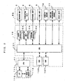
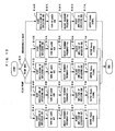
- Fig.2 is a block diagram showing an electrical arrangement of the image forming apparatus of Fig. 1 .
- This image forming apparatus is a so-called tandem color printer wherein photosensitive members 2Y, 2M, 2C, 2K for four colors of yellow Y, magenta M, cyan C and black K, as latent image carriers, are juxtaposed in an apparatus body 5.
- the apparatus is adapted to form a full-color image by superimposing toner images on the individual photosensitive members 2Y, 2M, 2C, 2K, or to form a monochromatic image using only the toner image of black (k).
- the image forming apparatus operates as follows.
- a CPU 111 of the main controller 11 sends a print command, based on which an engine controller 10 controls individual parts of an engine EG so as to form the image corresponding to the print command on a sheet S such as copy sheet, transfer sheet, paper and transparent sheet for OHP.
- charger units, developing units, exposure units and cleaners are provided in correspondence to the four photosensitive members 2Y, 2M, 2C, 2K, respectively. It is noted that these charger units, developing units, exposure units and cleaners for the respective color components are arranged the same ways. Therefore, the arrangement for the yellow color component is described here while individual parts of the arrangements for the other color components are represented by equivalent reference characters, respectively, and the description thereof is dispensed with.
- the exposure unit 6Y emits a light beam Ly toward the outside surface of the photosensitive member 2Y so charged by the charger unit 3Y Thus, an electrostatic latent image corresponding to yellow-image data included in the print command is formed on the photosensitive member 2Y
- the exposure unit 6Y operates based on a control command from an exposure controller 102Y ( Fig.4 ). Arrangements and operations of the exposure unit 6 and the exposure controller 102 will be described in details hereinlater.
- the electrostatic latent image thus formed is developed with toner by means of the developing unit 4Y
- the developing unit 4Y contains therein a yellow toner.
- a developing unit controller 104 applies a developing bias to a developing roller 41 Y
- the toner carried on the developing roller 41 Y is made to locally adhere to surface portions of the photosensitive member 2Y according to the surface potentials thereof.
- the electrostatic latent image on the photosensitive member 2Y is visualized as a yellow toner image.
- a DC voltage or a DC voltage superimposed with an AC voltage may be used as the developing bias to be applied to the developing roller 41 Y
- the developing bias may preferably have a waveform formed by superimposing a sinusoidal, triangular-wave or rectangular-wave AC voltage on the DC voltage for the purpose of efficient toner jumps.
- the yellow toner image developed by the developing unit 4Y is primarily transferred onto an intermediate transfer belt 71 of a transfer unit 7 in a primary transfer region TRy1.
- the other members for the other color components than yellow are arranged absolutely the same way as those for yellow.
- a magenta toner image, a cyan toner image and a black toner image are formed on the respective photosensitive members 2M, 2C, 2K and are primarily transferred onto the intermediate transfer belt 71 in respective primary transfer regions TRm1, TRc1, TRk1.
- the transfer unit 7 includes: the intermediate transfer belt 71 entrained about two rollers 72, 73; and a belt driver (not shown) operative to drive the roller 72 into rotation thereby rotating the intermediate transfer belt 71 in a predetermined rotational direction R2.
- the transfer unit is further provided with a secondary transfer roller 74 which confront the roller 73 with the intermediate transfer belt 71 interposed therebetween and which is adapted to be moved into contact with or away from a surface of the belt 71 by means of an unillustrated electromagnetic clutch.
- primary transfer timings are controlled to superimpose the individual toner images on each other thereby to form the color image on the intermediate transfer belt 71.
- the color image is secondarily transferred onto the sheet S taken out from a cassette 8 and delivered to a secondary transfer region TR2 between the intermediate transfer belt 71 and the secondary transfer roller 74.
- a monochromatic image is transferred onto the sheet S
- only a black toner image is formed on the photosensitive member 2k and the monochromatic image is secondarily transferred onto the sheet S delivered to the secondary transfer region TR2.
- the sheet S thus secondarily transferred with the image is transported to a discharge tray at a top surface of the apparatus body via a fixing unit 9.
- the photosensitive members 2Y, 2M, 2C, 2K After the primary transfer of the toner images to the intermediate transfer belt 71, the photosensitive members 2Y, 2M, 2C, 2K have their the surface potentials reset by unillustrated static eliminators. In addition, the photosensitive members are removed of the toners remaining on their surfaces by means of the cleaners. Then, the photosensitive members are subjected to the subsequent charging by means of the charger units 3Y, 3M, 3C, 3K.
- a transfer belt cleaner 75 Disposed in the vicinity of the roller 72 are a transfer belt cleaner 75, a density sensor 76 ( Fig.2 ) and a vertical synchronous sensor 77 ( Fig.2 ).
- the cleaner 75 is adapted to be moved into contact with or away from the roller 72 by means of an unillustrated electromagnetic clutch. As moved to the roller 72, the cleaner 75 holds its blade against the surface of the intermediate transfer belt 71 entrained about the roller 72 thereby removing the toner remaining on the outside surface of the intermediate transfer belt 71 after the secondary image transfer.
- the density sensor 76 confronts the surface of the intermediate transfer belt 71 for sensing optical densities of patch images formed on the outside surface of the intermediate transfer belt 71.
- the vertical synchronous sensor 77 is a sensor for detecting a reference position of the intermediate transfer belt 71.
- the sensor functions as a vertical synchronous sensor for outputting a synchronous signal or a vertical synchronous signal Vsync in association with a drivable rotation of the intermediate transfer belt 71 in a sub-scan direction.
- operation timings of the individual parts are synchronized while the operations of the individual parts of the apparatus are controlled based on the vertical synchronous signal Vsync such as to superimpose the toner images of the respective colors on each other precisely.
- a reference numeral 113 represents an image memory provided in the main controller 11 for storing image data supplied from the external apparatus such as the host computer via an interface 112.
- a reference numeral 106 represents a ROM for storing operation programs executed by a CPU 101, control data used for controlling the engine EG, resonant frequencies of deflectors to be described hereinlater, and the like.
- a reference numeral 107 represents a RAM for temporarily storing the operation results given by the CPU 101, and other data.
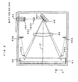
- Fig.3 is a sectional view taken on a main-scan direction for showing an arrangement of the exposure unit provided in the image forming apparatus of Fig.1 .
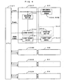
- Fig.4 is a block diagram showing arrangements of the exposure unit and the exposure controller in the image forming apparatus of Fig.1 .
- the exposure unit 6 and the exposure controller 102 for the respective color components are arranged the same ways. Therefore, the arrangement for the yellow color component is described here while the individual parts of the arrangements for the other color components are represented by equivalent reference characters, respectively, and the description thereof is dispensed with.
- the exposure unit 6Y (6M, 6C, 6K) includes an exposure casing 61.
- the exposure casing 61 has a single exposure light source 62Y fixed thereto so as to be capable of emitting the light beam from the laser light source 62Y
- the laser light source 62Y is electrically connected with a light source driver 1021 of the exposure controller 102Y
- the light source driver 1021 provides ON/OFF control of the laser light source 62Y according to an image signal, so that the laser light source 62Y emits the light beam modulated in correspondence to the image data.
- a collimator lens 631 for scanning the light beam from the laser light source 62Y on the surface of the photosensitive member 2Y
- the light beam from the laser light source 62Y is shaped into a collimated beam of a suitable size by means of the collimator lens 631 and then, is made incident on the cylindrical lens 632 powered only in a sub-scan direction Y
- the collimated beam is focused onto place near a deflective mirror 651 of the deflector 65Y with respect to the sub-scan direction Y
- a combination of the collimator lens 631 and the cylindrical lens 632 functions as a beam shaping system 63 for shaping the light beam from the laser light source 62Y
- the deflector 65Y is formed using a micromachining technique which applies a semiconductor fabrication technique in integrally forming micro machines on a semiconductor substrate.
- the deflector comprises an oscillation mirror adapted for resonant oscillations.
- the deflector 65Y is capable of deflecting the light beam in a main-scan direction X by means of the deflective mirror 651 in resonant oscillations.
- the deflective mirror 651 is carried in a manner to be oscillatble about an oscillatory axis (torsion spring) extending substantially perpendicular to the main-scan direction.
- the deflective mirror oscillates about the oscillatory axis according to an external force applied from an operating section 652.
- the operating section 652 applies an electrostatic, electromagnetic or mechanical external force to the deflective mirror 651 based on a mirror drive signal from a mirror driver 1022 of the exposure controller 102Y, thereby causing the deflective mirror 651 to oscillate at a frequency of the mirror drive signal.
- the operating section 652 may adopt any of the drive methods based on electrostatic attraction, electromagnetic force and mechanical force. These drive methods are known in the art and hence, the description thereof is dispensed with.
- the mirror driver 1022 can be reprogrammed to change drive conditions including the frequency, voltage and the like of the mirror drive signal. As will be described hereinlater, the mirror driver can be reprogrammed to change the frequency of the mirror drive signal to an optimum value determined from the resonant frequencies of the deflectors 65Y, 65M, 65C, 65K. The mirror driver is also adapted to adjust an amplitude value by changing the voltage of the mirror drive signal.
- the light beam deflected by the deflective mirror 651 of the deflector 65Y is directed toward the scanning lens 66.
- the scanning lens 66 is arranged to have a substantially constant F-value with respect to the overall effective scan region on the surface of the photosensitive member 2. Therefore, the light beam deflected to the scanning lens 66 passes therethrough to be focused onto the effective scan region on the photosensitive member 2Y in a spot of a substantially constant diameter.
- the light beam is scanned in parallel to the main-scan direction X so as to form, on the photosensitive member 2, a linear latent image extending in the main-scan direction X.
- Scan-beam detection signals from these horizontal synchronous sensors 60A, 60B are transmitted to a measuring section 1024 of the exposure controller 102Y so that the measuring section calculates a scan time during which the light beam is scanned on the effective scan region.
- the scan time calculated by the measuring section 1024 is transmitted to the mirror driver 1022, so that the mirror driver 1022 can reprogram the drive conditions of the mirror drive signal according to the scan time thus supplied, the drive conditions under which the deflective mirror 651 is driven.
- the horizontal synchronous sensors 60A, 60B also function as horizontal synchronous read sensors for providing a synchronous signal or horizontal synchronous signal Hsync for causing the light beam to be scanned on the effective scan region in the main-scan direction X.
- a start-up process is performed at power-on or prior to the start of printing in order to make adjustment to ensure that the light beam may preferably be scanned by the deflector 65 (65Y, 65M, 65C, 65K). More specifically, the following start-up process is performed.
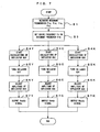
- Fig. 5 is a flow chart showing the start-up process performed by the image forming apparatus of Fig. 1 .
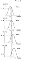
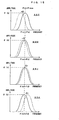
- Fig.6 is a group of diagrams schematically showing the start-up process shown in Fig. 5 .
- the CPU 101 retrieves resonant frequencies Fry, Frm, Frc, Frk of the deflectors 65Y, 65M, 65C, 65K previously stored in the ROM 106 (Step S1).
- the ROM 106 functions as a "storage unit", but the unit to store the resonant frequencies Fry, Frm, Frc, Frk is not limited to this.
- each of the exposure controllers 102Y, 102M, 102C, 102k may be provided with a memory in which the resonant frequency may be stored.
- the CPU 101 calculates an average value Frave of the resonant frequencies Fry, Frm, Frc, Frk as an "optimum value" (Step S2).
- the CPU applies a drive command to the respective mirror drivers 1022 of the exposure units 6Y, 6M, 6C, 6K such that all the deflectors 65Y, 65M, 65C, 65K may oscillate at the average value Frave.
- the mirror driver 1022 sets the frequency of the drive signal or a drive frequency Fd to the average value Frave (Step S3) and drives the deflectors 65Y, 65M, 65C, 65K into oscillations simultaneously.
- the light source driver 1021 outputs a light-source drive signal to the laser light source 62Y so as to turn on the laser light source 62Y (Step S5Y).
- the deflector 65 is already in oscillations.
- the light beam is scanned on the surface of the photosensitive member 2Y so as to be prevented from being intensively irradiated on a part of the photosensitive member 2Y
- the horizontal synchronous sensors 60A, 60B output the horizontal synchronous signal Hsync.
- the drive voltage of the mirror drive signal applied from the mirror driver 1022 to the deflector 65 is controlled based on the sensor outputs so as to adjust the amplitude value of the deflector 65Y, whereby the speed of the light beam Ly is adjusted. This ensures that the light beam Ly is scanned stably.
- the laser light source 62 is turned off.
- the exposure controller outputs a Ready signal to the CPU 101 to complete the start-up process for the yellow exposure unit 6Y
- this embodiment carries out the start-up processes on all the toner colors in parallel.
- the CPU 101 receives the Ready signals for all the toner colors at completion of the start-up processes on all the toner colors, the CPU 101 performs a color print process according to a color print command.
- the embodiment is arranged such that even though the resonant frequencies Fry, Frm, Frc, Frk of the deflectors 65Y, 65M, 65C, 65K for the individual toner colors are different from one another as shown in Fig.6 , for example, the deflectors are driven at the average value Frave of these frequencies. Hence, the amount of deviation of the drive frequency Fd (Frave) from each of the resonant frequencies Fry, Frm, Frc, Frk is decreased.
- the deflective mirrors 651 of the deflectors 65 may be driven into the resonant oscillations at the same drive frequency Fd.
- each of the deflective mirrors 651 may have an adequate amplitude. This results in the formation of images of high quality.
- the average value Frave of the resonant frequencies Fry, Frm, Frc, Frk is defined as the "optimum value" as shown in Fig.6 , so that the drive frequency Fd is set to the average value Frave.
- a frequency range between the maximum value and the minimum value (inclusive) of these resonant frequencies Fry, Frm, Frc, Frk may be defined as an adjustment range, within which the optimum value of the drive frequency may be decided.
- While one of the resonant frequencies Fry, Frm, Frc, Frk may also be defined as the "optimum value", it is preferred to select the closest value to the median (Second Embodiment). Referring to Fig.7 and Fig.8 , a second embodiment is described as below.
- Fig.7 is a flow chart showing the second embodiment of the image forming apparatus.
- Fig.8 is a group of diagrams schematically showing the operations of the second embodiment.
- the resonant frequencies Fry, Frm, Frc, Frk of the deflectors 65Y, 65M, 65C, 65K stored in the ROM 106 are retrieved (Step S1). Out of these resonant frequencies Fry, Frm, Frc, Frk, the resonant frequency Frm of the magenta deflector 65M, which is the closest to the median, is selected as the "optimum value".
- the drive frequency Fd is set to the resonant frequency Frm (Step S3) and the deflectors 65Y, 65M, 65C, 65K are driven into oscillations simultaneously. It is noted here that the magenta deflector attains the adequate amplitude because the drive frequency Fd coincides with the resonant frequency Frm thereof.
- this embodiment carries out the start-up processes on all the toner colors in parallel. Receiving the Ready signals for all the toner colors at completion of the start-up processes on all the toner colors, the CPU 101 performs the color print process according to the color print command.
- the second embodiment also permits, likewise to the first embodiment, all the exposure units 6Y, 6M, 6C, 6K to drive the deflective mirrors 651 of the deflectors 65 into the resonant oscillations at the same drive frequency Fd as well as to attain the adequate amplitudes of the respective deflective mirrors 651.
- the drive frequency Fd coincides with the resonant frequency Frm of the magenta deflector 65M and hence, what is to be done is to subject the deflectors for the remaining three colors to the adjustment of the light beam speed based on the amplitude adjustment.
- the start-up process may be performed efficiently.
- the second embodiment sets the drive frequency Fd to the resonant frequency Frm of the magenta deflector 65M, it goes without saying that the drive frequency may be set to the resonant frequency of the deflector 65 for any other toner color.
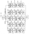
- Fig.9 is a block diagram showing an arrangement of a third embodiment of the exposure unit and the exposure controller of the image forming apparatus of Fig. 1 .
- the arrangements and operations of the exposure unit 6 and of the exposure controller 102 are described in details.
- the exposure unit 6 and the exposure controller 102 for the respective color components are arranged the same ways. Therefore, the arrangement for the yellow color is described here while the individual parts of the arrangements for the other color components are represented by equivalent reference characters, respectively, and the description thereof is dispensed with.
- the deflector 65Y is provided with a resonant-frequency adjusting section 653 as disclosed in Japanese Unexamined Patent Publication No.9-197334 , for example.
- this resonant-frequency adjusting section 653 includes an electrical resistance element formed at the torsion spring (not shown) of the deflector 65.
- the electrical resistance element is electrically connected with a frequency controller 1023 of the exposure controller 102Y
- the frequency controller 1023 controls power supply to the electrical resistance element so as to vary the temperature of the torsion spring.
- the spring constant of the torsion spring so that the resonant frequency of the deflector 65 can be varied.
- the embodiment operates the resonant-frequency adjusting section 653 to vary the resonant frequency of the deflector 65 for substantially matching the resonant frequency with the drive frequency. It is noted that a specific arrangement for varying the resonant frequency of the deflector 65 is not limited to this, and any conventionally known arrangement may be adopted.
- the scan time during which the light beam is scanned on the effective scan region is transmitted to the frequency controller 1023, the scan time calculated by the measuring section 1024 based on the scan-beam detection signals from the aforesaid horizontal synchronous sensors 60A, 60B.
- the frequency controller 1023 adjusts the resonant frequency of the deflector 65.
- the scan time is also transmitted to the mirror driver 1022.
- the mirror driver 1022 can be reprogrammed to change the drive conditions of the mirror drive signal according to the scan time so transmitted, the mirror drive signal used for driving the deflective mirror 651.
- the horizontal synchronous sensors 60A, 60B also function as the horizontal synchronous read sensors for providing the synchronous signal or the horizontal synchronous signal Hsync for causing the light beam to be scanned on the effective scan region in the main-scan direction X.
- the apparatus When the apparatus of the aforementioned arrangement receives a print command in a state where the deflector 65 (65Y, 65M, 65C, 65K) is out of oscillations, the apparatus performs a start-up process before starting a printing operation such as to make adjustment for ensuring that the light beam may preferably be scanned by means of the deflector 65. More specifically, the following start-up process is performed.
- Fig. 10 is a flow chart showing the third embodiment of the image forming apparatus.
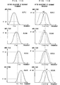
- Figs. 11A and 11B are groups of diagrams schematically showing adjustment processes for the deflector 65 which are performed prior to color printing in a color print mode shown in Fig.10 .
- Step S9 whether the print command indicates the color print mode or a monochromatic print mode is determined in Step S9.
- the adjustment process for the deflector 65 is performed on all the toner colors.
- Step S4Y a series of processings (Steps S4Y, S5Y, S8Y, S6Y, S7Y) are performed on the yellow color in this adjustment process.
- a mirror drive signal having a predetermined drive frequency Fd is applied from the mirror driver 1022 to the deflector 65Y prior to turn-on of the laser light source 62Y, thereby driving the deflective mirror 651 of the deflector 65Y into oscillations (Step S4Y).
- the deflective mirror 651 oscillates at the frequency Fd, as shown in Fig.11A , for example.
- Step S5Y and Step S8Y are performed for substantially matching the resonant frequency Fry with the drive frequency Fd, thereby adjusting the amplitude ⁇ (y) to the maximum amplitude.
- the light source driver 1021 outputs the light-source drive signal to the laser light source 62Y so as to turn on the laser light source 62Y (Step S5Y).
- the deflector 65 is already in oscillations. Hence, the light beam is scanned on the surface of the photosensitive member 2Y so as to be prevented from being intensively irradiated on a part of the photosensitive member 2Y In synchronism with the scanning of the light beam, the horizontal synchronous sensors 60A, 60B output the horizontal synchronous signal Hsync.
- the frequency controller 1023 controls the power supply to the electrical resistance element based on the sensor outputs so as to vary the temperature of the torsion spring of the deflector 65Y, whereby a (pre-adjustment) resonant characteristic of the deflector 65Y, as indicated by a broken line in Fig.11B , is shifted to the drive frequency side.
- the drive voltage of the mirror drive signal applied from the mirror driver 1022 to the deflector 65 is controlled based on the sensor outputs so as to adjust the maximum amplitude of the deflector 65Y, whereby the speed of the light beam Ly is adjusted (Step S6Y). This ensures that the light beam Ly is scanned stably.
- the laser light source 62 is turned off.
- the exposure controller outputs the Ready signal to the CPU 101 to complete the start-up process for the yellow exposure unit 6Y
- Steps S4C, S5C, S8C, S6C, S7C are performed on the cyan color to match the resonant frequency Frc of the deflector 65C substantially with the drive frequency Fd, to adjust the speed of the light beam Lc and thereafter, to output the Ready signal to the CPU 101 to complete the start-up process for the cyan exposure unit 6C.
- Steps S4K, S5K, S8K, S6K, S7K are performed on the black color to match the resonant frequency Frk of the deflector 65K substantially with the drive frequency Fd, to adjust the speed of the light beam Lk and thereafter, to output the Ready signal to the CPU 101 to complete the start-up process for the black exposure unit 6K.
- the CPU 101 receives the Ready signals for all the toner colors at completion of the start-up processes on all the toner colors, the CPU 101 performs the color print process according to the color print command.
- Step S9 determines the print command to indicate the monochromatic print
- a series of processings (Steps S4K, S5K, S8K, S6K, S7K) are performed only on the black color to match the resonant frequency Frk of the deflector 65K substantially with the drive frequency Fd, to adjust the speed of the light beam Lk and thereafter, to output the Ready signal to the CPU 101 to complete the start-up process for the black exposure unit 6K.
- the CPU 101 receives the Ready signal, the CPU 101 performs a monochromatic print process according to the monochromatic print command.
- the embodiment is adapted to adjust the resonant frequencies of the deflectors 65 (65Y, 65M, 65C, 65K) by controlling the resonant-frequency adjusting sections 653 for the respective toner colors by means of the frequency controllers 1023. Since the resonant frequencies Fry, Frm, Frc, Frk of the individual deflectors 65 are so adjusted as to be substantially in coincidence with the drive frequency Fd, all the deflectors 65 are driven into resonant oscillations at the predetermined frequency Fd and besides, in the maximum amplitude. This results in the formation of images of high quality.
- the start-up process may be performed efficiently because when the print command indicates the monochromatic print, the adjustment of the deflector 65 is performed only on the black color which is required for the monochromatic printing.
- the start-up process may be performed at power-on. In such a case, the deflector 65 may be subjected to the adjustment process similar to that performed for color printing.
- the adjustment may be made on the drive frequency, as shown in Fig. 12 , in a manner that the drive frequency Fd is so varied as to coincide with the resonant frequency Frk of the deflector 65K.
- the monochromatic print negates the need for superimposing the toner images on each other on the intermediate transfer belt 71 or for matching the amplitudes of the deflectors 65 for the individual colors with each other.
- some degree of variations of the drive frequency Fd impose a minor influence on the monochromatic image and are negligible in practical terms. What is more, adjusting the frequency Fd of the mirror drive signal is easier than adjusting the resonant frequency Frk via temperature control.
- the former adjustment is more excellent in response than the latter adjustment.
- a drive period of the deflector 65 is also varied. It is therefore preferred to vary the operating speeds of the individual parts of the apparatus according to the varied drive frequency Fd. By providing such controls, it is ensured that the monochromatic images are formed in a stable manner and also in high quality.
- the above first and second embodiments cannot completely eliminate the deviation between the optimum value and the respective resonant frequencies although the drive frequency Fd is set to the optimum value. Hence, these embodiments may encounter a degree of limit in the adjustment of the deflector. On this account, an arrangement may be made such that, as suggested by the above third embodiment, the resonant frequencies of the exposure units 6 for the individual toner colors are so varied as to coincide substantially with the drive frequency Fd. Referring to Fig. 13 to Fig. 15 , a fourth embodiment is described as below.
- Fig. 13 is a block diagram showing an image forming apparatus according to the fourth embodiment.
- the fourth embodiment includes the resonant-frequency adjusting sections 653 for the respective deflectors 6Y, 6M, 6C, 6K, and controls the resonant-frequency adjusting sections 653 via the respective frequency controllers 1023 for varying the respective resonant frequencies substantially to the drive frequency Fd.
- the fourth embodiment significantly differs from the first embodiment. Therefore, the description on the fourth embodiment focuses on the difference from the first embodiment while like components are represented by the same reference characters, respectively, the description of which is dispensed with.
- the yellow exposure unit 6Y is provided with the resonant-frequency adjusting section 653 for varying the resonant frequency of the deflector 65Y
- the resonant-frequency adjusting section 653 may adopt the arrangement disclosed in Japanese Unexamined Patent Publication No.9-197334 , for example.
- the torsion spring (not shown) of the deflector 65 is formed with the electrical resistance element, which is electrically connected with the frequency controller 1023 of the exposure controller 102Y
- the frequency controller 1023 controls the power supply to the electrical resistance element so as to vary the temperature of the torsion spring.
- the spring constant of the torsion spring so that the resonant frequency Fry of the deflector 65Y may be varied.
- the scan time calculated by the measuring section 1024 is transmitted to the frequency controller 1023, which in turn, controls the power supply to the resonant-frequency adjusting section 653 so as to vary the resonant frequency of the deflector 65Y for substantially matching the resonant frequency thereof with the drive frequency Fd.
- a specific arrangement for varying the resonant frequency of the deflector 65Y is not limited to this, and any conventionally known arrangement may be adopted.
- the exposure units for the other toner colors are arranged the same way.
- Fig. 14 is a flow chart showing the start-up process performed by the image forming apparatus of Fig. 13 .
- Fig. 15 is a group of diagrams schematically showing the start-up process of Fig. 14 .
- the start-up process is performed as follows. Just as in the first embodiment, the CPU 101 calculates the average value Frave of the resonant frequencies Fry, Frm, Frc, Frk of the deflectors 65Y, 65M, 65C, 65K previously stored in the ROM 106 and causes the deflectors 65Y, 65M, 65C, 65K to oscillate with the drive frequency Fd set to the average value Frave.
- Steps S4Y to S8Y are performed on the yellow color, as shown in Fig. 14 . That is, after the lapse of a predetermined period of time from the start of oscillations of the deflector 65Y, the light source driver 1021 outputs the light-source drive signal to the laser light source 62Y so as to turn on the laser light source 62Y (Step S5Y). In synchronism with the scanning of the light beam, the horizontal synchronous sensors 60A, 60B output the horizontal synchronous signal Hsync.
- the frequency controller 1023 controls the power supply to the electric resistance element based on the sensor outputs so as to vary the temperature of the torsion spring of the deflector 65Y, whereby the (pre-adjustment) resonant characteristic of the deflector 65Y, as indicated by a broken line in the uppermost diagram of Fig. 15 , is shifted to the drive frequency side.
- Step S6Y the drive voltage of the mirror drive signal applied from the mirror driver 1022 to the deflector 65 is controlled based on the sensor outputs so as to adjust the maximum amplitude value of the deflector 65Y, whereby the speed of the light beam Ly is adjusted.
- Step S6Y the drive voltage of the mirror drive signal applied from the mirror driver 1022 to the deflector 65 is controlled based on the sensor outputs so as to adjust the maximum amplitude value of the deflector 65Y, whereby the speed of the light beam Ly is adjusted.
- the laser light source 62 is turned off.
- step S7Y the exposure controller outputs the Ready signal to the CPU 101 to complete the start-up process for the yellow exposure unit 6Y
- Steps S4M to S8M are performed on the magenta color to match the resonant frequency Frm of the deflector 65M substantially with the drive frequency Fd, to adjust the scan speed of the light beam Lm and thereafter, to output the Ready signal to the CPU 101 to complete the start-up process for the magenta exposure unit 6M.
- Steps S4C to S8C are performed on the cyan color to match the resonant frequency Frc of the deflector 65C substantially with the drive frequency Fd, to adjust the scan speed of the light beam Lc, and thereafter, to output the Ready signal to the CPU 101 to complete the start-up process for the cyan exposure unit 6C.
- a series of processings are performed on the black color to match the resonant frequency Frk of the deflector 65K substantially with the drive frequency Fd, to adjust the scan speed of the light beam Lk and thereafter, to output the Ready signal to the CPU 101 to complete the start-up process for the black exposure unit 6k.
- the fourth embodiment is adapted to set the drive frequency Fd to the optimum value.
- the embodiment controls the resonant-frequency adjusting sections 653 for the respective toner colors by means of the frequency controllers 1023, thereby adjusting the resonant frequencies Fry, Frm, Frc, Frk of the individual deflectors 65 in a manner to match the resonant frequencies Fry, Frm, Frc, Frk substantially with the optimum drive frequency Fd. Therefore, all the deflectors 65 are driven into resonant oscillations at the predetermined frequency Fd and besides, in the maximum amplitude. This results in the formation of images of high quality.
- the third and fourth embodiments for example, adjust the resonant frequencies Fry, Frm, Frc, Frk of the deflectors 65 (65Y, 65M, 65C, 65K) based on the horizontal synchronous signal Hsync from the horizontal synchronous sensors 60A, 60B
- the information usable for the adjustment of the resonant frequency is not limited to the horizontal synchronous signal Hsync but any information related to the resonant frequency may be used.
- a displacement detection sensor such as disclosed in Japanese Unexamined Patent Publication No.7-218857 may be provided at the deflector 65 for detecting the amount of displacement of the deflective mirror 651, while the resonant frequency Fry, Frm, Frc, Frk of the deflector 65 may be adjusted based on the detection value.
- the arrangement of the resonant-frequency adjusting section 653 is not limited to this.
- the resonant frequency may be adjusted by the conventionally known methods.
- the deflector 65 formed using the micromachining technique is employed as the oscillation mirror.
- the invention is applicable to all kinds of image forming apparatuses which use oscillation mirrors adapted for resonant oscillations for deflecting the light beam thereby scanning the light beam on the latent image carrier.
Claims (5)
- Appareil de formation d'images comprenant :une pluralité de supports d'images latentes (2) ;une pluralité d'unités d'exposition (6) chacune prévue en correspondance avec un support d'images latentes (2) respectif, chacune des unités d'exposition (6) comportant une source de lumière (62) et un miroir oscillant (651), et étant adaptée pour former une image latente sur le support d'images latentes (2) respectif en déviant un faisceau lumineux d'une source de lumière (62) en un faisceau lumineux dévié (L0) au moyen du miroir oscillant (651) en oscillations et en balayant le faisceau lumineux dévié (L0) sur le support d'images latentes ;une pluralité d'unités de développement (4, 41), chacune prévue en correspondance avec l'un de la pluralité de supports d'images latentes (2) respectifs, la pluralité d'unités de développement (4, 41) étant adaptées pour former une pluralité d'images constituées de toners de différentes couleurs en développant les images latentes avec des toners de différentes couleurs, respectivement,dans lequel une opération d'impression couleur ou une opération d'impression monochromatique peut être effectuée au choix, l'opération d'impression couleur consistant à former une image couleur en formant les images constituées de toner de différentes couleurs au moyen des unités de développement (41) et en superposant les images constituées de toners de différentes couleurs les unes sur les autres sur un support de transfert (71), l'opération d'impression monochromatique consistant à former une image monochrome en formant une image constituée de toner au moyen de l'une parmi les unités de développement (41) pour une couleur spécifique de la pluralité de couleurs et en transférant l'image constituée de toner à un support de transfert (71),une unité d'entraînement (102, 1022) pour appliquer un signal d'entraînement ayant une fréquence d'entraînement prédéterminée à chaque miroir oscillant (65, 651) pour entraîner le miroir oscillant ; et capable de varier la fréquence d'entraînement du signal d'entraînement ;une unité de réglage (653) pour régler les fréquences de résonnance des miroirs oscillants (65, 651), respectivement ; etun appareil de commande (102, 1023) de telle sorte que lors de l'exécution de l'opération d'impression couleur l'appareil de commande soit adapté pour commander l'unité de réglage (653) de manière à faire sensiblement concorder toutes les fréquences de résonnance des miroirs oscillants (65, 651) avec la fréquence d'entraînement, et de telle sorte que lors de l'exécution de l'opération d'impression monochromatique l'appareil de commande soit adapté pour commander l'unité d'entraînement (102, 1022) de manière à faire sensiblement concorder la fréquence d'entraînement du signal d'entraînement avec la fréquence de résonnance du miroir oscillant (165, 651) correspondant à la couleur spécifique.
- Appareil de formation d'images selon la revendication 1, dans lequel dans le cas où l'on fait varier la fréquence d'entraînement du signal d'entraînement en vue d'exécuter l'opération d'impression monochromatique, l'appareil de commande (102) est adapté pour faire varier des vitesses de fonctionnement des différentes parties de l'appareil en fonction de la variation de la fréquence d'entraînement.
- Appareil de formation d'images selon la revendication 1, dans lequel l'unité d'entrainement (102, 1022) comprend une pluralité de dispositifs d'entraînement (1022) chacun prévu en correspondance aux miroirs oscillants (651) respectifs, chacun des dispositifs d'entraînement (1022) appliquant le signal d'entraînement au miroir oscillant pour entraîner le miroir oscillant.
- Appareil de formation d'images selon la revendication 3, comprenant en outre une pluralité de détecteurs d'amplitude (60A, 60B) chacun prévu en correspondance aux miroirs oscillants (651) respectifs et détectant une amplitude du miroir oscillant (651),
dans lequel les dispositifs d'entraînement (1022) règlent les amplitudes des miroirs oscillants (651) sur la base des sorties délivrées des détecteurs d'amplitude (60A, 60B), respectivement. - Procédé de formation d'images, comprenant :une étape de préparation qui consiste à préparer une pluralité de supports d'images latentes (2) chacun capable de former une image latente sur sa surface ;une étape qui consiste à préparer une pluralité d'unités d'exposition (6) chacune prévue en correspondance avec un support d'images latentes (2) respectif, chacune des unités d'exposition (6) comportant une source de lumière (62) et un miroir oscillant (651) ;une étape de détermination (S9) qui consiste à déterminer si une opération d'impression couleur ou une opération d'impression monochromatique doit être effectuée ;une étape de formation d'images latentes qui consiste à dévier un faisceau lumineux provenant d'une source de lumière (62) au moyen d'un miroir oscillant (651) qui oscille à une fréquence d'entraînement prédéterminée et à balayer le faisceau lumineux dévié (L0), dans l'opération d'impression couleur à partir de chacune desdites unités d'exposition (6) sur chaque support d'images latentes respectif, et dans l'opération d'impression monochromatique à partir d'une desdites unités d'exposition (6) sur le support d'images latentes respectif pour une couleur spécifique ;une étape de développement qui consiste à développer les images latentes, dans l'opération d'impression couleur, en formant des images constituées de toners de différentes couleurs, et dans l'opération d'impression monochromatique, en formant une image monochrome en formant une image constituée de toner pour la couleur spécifique ;une étape de transfert qui consiste, dans l'opération d'impression couleur, à superposer les images constituées de toners de différentes couleurs les unes sur les autres sur un support de transfert (71), et dans l'opération d'impression monochromatique, à transférer l'image constituée de toner à un support de transfert (71) ; etune étape de réglage, effectuée avant l'étape de formation d'images latentes, qui consiste, lors de l'exécution de l'opération d'impression couleur, à faire sensiblement concorder toutes les fréquences de résonnance des miroirs oscillants (65, 651) avec la fréquence d'entraînement, et, lors de l'exécution de l'opération d'impression monochromatique, à faire sensiblement concorder la fréquence d'entraînement du signal d'entraînement avec la fréquence de résonnance du miroir oscillant (165, 651) correspondant à la couleur spécifique.
Applications Claiming Priority (4)
| Application Number | Priority Date | Filing Date | Title |
|---|---|---|---|
| JP2004124574A JP2005305770A (ja) | 2004-04-20 | 2004-04-20 | 画像形成装置および画像形成方法 |
| JP2004124574 | 2004-04-20 | ||
| JP2004124573A JP4457738B2 (ja) | 2004-04-20 | 2004-04-20 | 画像形成装置 |
| JP2004124573 | 2004-04-20 |
Publications (3)
| Publication Number | Publication Date |
|---|---|
| EP1589365A2 EP1589365A2 (fr) | 2005-10-26 |
| EP1589365A3 EP1589365A3 (fr) | 2007-08-29 |
| EP1589365B1 true EP1589365B1 (fr) | 2011-09-14 |
Family
ID=34935398
Family Applications (1)
| Application Number | Title | Priority Date | Filing Date |
|---|---|---|---|
| EP05008545A Expired - Fee Related EP1589365B1 (fr) | 2004-04-20 | 2005-04-19 | Dispositif et procédé de formation d'image |
Country Status (2)
| Country | Link |
|---|---|
| US (2) | US7639274B2 (fr) |
| EP (1) | EP1589365B1 (fr) |
Families Citing this family (5)
| Publication number | Priority date | Publication date | Assignee | Title |
|---|---|---|---|---|
| JP2007086677A (ja) * | 2005-09-26 | 2007-04-05 | Seiko Epson Corp | 画像形成装置および画像形成方法 |
| JP4986479B2 (ja) * | 2006-03-03 | 2012-07-25 | 株式会社リコー | 光走査装置および画像形成装置 |
| JP4511613B2 (ja) | 2008-06-20 | 2010-07-28 | シャープ株式会社 | 光走査装置、画像形成装置 |
| JP2010014871A (ja) * | 2008-07-02 | 2010-01-21 | Canon Inc | 揺動体装置、光偏向装置、光学機器、及び共振周波数検出方法 |
| US11474425B2 (en) * | 2019-08-14 | 2022-10-18 | Stmicroelectronics Ltd | Driving multiple resonance MEMS mirrors with a single frequency |
Family Cites Families (16)
| Publication number | Priority date | Publication date | Assignee | Title |
|---|---|---|---|---|
| US4541061A (en) * | 1982-10-13 | 1985-09-10 | Minnesota Mining And Manufacturing Company | Data clocking circuitry for a scanning apparatus |
| JPH01302317A (ja) | 1988-05-31 | 1989-12-06 | Konica Corp | 画像形成装置 |
| JP2981600B2 (ja) | 1996-01-17 | 1999-11-22 | オムロン株式会社 | 光スキャナおよびそれを用いた光センサ装置 |
| JPH09240060A (ja) | 1996-03-04 | 1997-09-16 | Ricoh Co Ltd | 画像形成方法及び画像形成装置 |
| JP2001013417A (ja) | 1999-07-01 | 2001-01-19 | Keyence Corp | 光走査装置 |
| US7423787B2 (en) * | 2001-03-01 | 2008-09-09 | Ricoh Company, Ltd. | Optical scanning module, device, and method, and imaging apparatus |
| JP2002292933A (ja) * | 2001-03-30 | 2002-10-09 | Canon Inc | カラー画像形成装置およびそのレーザパルス幅調整方法 |
| US7068296B2 (en) * | 2001-09-14 | 2006-06-27 | Ricoh Company, Ltd. | Optical scanning device for reducing a dot position displacement at a joint of scanning lines |
| US6972883B2 (en) * | 2002-02-15 | 2005-12-06 | Ricoh Company, Ltd. | Vibration mirror, optical scanning device, and image forming using the same, method for making the same, and method for scanning image |
| US7532227B2 (en) * | 2002-07-02 | 2009-05-12 | Ricoh Company, Ltd. | Optical scanner and image forming apparatus |
| JP4219631B2 (ja) | 2002-07-19 | 2009-02-04 | 株式会社リコー | 光走査装置および画像形成装置 |
| JP2004191416A (ja) | 2002-12-06 | 2004-07-08 | Ricoh Co Ltd | 光走査装置および画像形成装置 |
| US6956597B2 (en) * | 2002-12-23 | 2005-10-18 | Lexmark International, Inc. | Scanning with multiple oscillating scanners |
| EP2107412A1 (fr) * | 2003-02-17 | 2009-10-07 | Seiko Epson Corporation | Système à balayage |
| JP2005031238A (ja) | 2003-07-09 | 2005-02-03 | Ricoh Co Ltd | 偏向ミラー、光走査装置、および画像形成装置 |
| US7233343B2 (en) * | 2004-11-24 | 2007-06-19 | Texas Instruments Incorporated | Serial printing with multiple torsional hinged MEMS mirrors |
-
2005
- 2005-04-12 US US11/104,289 patent/US7639274B2/en not_active Expired - Fee Related
- 2005-04-19 EP EP05008545A patent/EP1589365B1/fr not_active Expired - Fee Related
-
2009
- 2009-06-12 US US12/483,687 patent/US20090252512A1/en not_active Abandoned
Also Published As
| Publication number | Publication date |
|---|---|
| US20050259143A1 (en) | 2005-11-24 |
| EP1589365A3 (fr) | 2007-08-29 |
| US20090252512A1 (en) | 2009-10-08 |
| EP1589365A2 (fr) | 2005-10-26 |
| US7639274B2 (en) | 2009-12-29 |
Similar Documents
| Publication | Publication Date | Title |
|---|---|---|
| EP1450198B1 (fr) | Système à balayage | |
| US7710625B2 (en) | Light scanning apparatus that stops driving oscillation mirror when change of amplitude of oscillation mirror exceeds predetermine value | |
| EP1622355A2 (fr) | Appareil de formation d'image, procedé de formation d'image et système de commande de données | |
| EP1589365B1 (fr) | Dispositif et procédé de formation d'image | |
| JP4701907B2 (ja) | 光走査装置および該装置の制御方法 | |
| US7557822B2 (en) | Apparatus for and method of forming image using oscillation mirror | |
| JP2007185786A (ja) | 光走査装置及び該装置の制御方法 | |
| US7480087B2 (en) | Apparatus for and method of forming images with oscillation mirror | |
| JP4720368B2 (ja) | 光走査装置および該装置の制御方法 | |
| JP4457738B2 (ja) | 画像形成装置 | |
| JP4701593B2 (ja) | 光走査装置および画像形成装置 | |
| JP2005208460A (ja) | 光走査装置および画像形成装置 | |
| JP4465970B2 (ja) | 画像形成装置 | |
| JP4830319B2 (ja) | 画像形成方法 | |
| JP2007185856A (ja) | 光走査装置及び該装置の制御方法 | |
| JP2010006068A (ja) | 画像形成装置および画像形成方法 | |
| JP4831228B2 (ja) | 画像形成装置および画像形成方法 | |
| JP2005305770A (ja) | 画像形成装置および画像形成方法 | |
| JP2007098737A (ja) | 画像形成方法 | |
| JP2011123511A (ja) | 光走査装置、画像形成装置および画像形成方法 | |
| JP4830320B2 (ja) | 画像形成装置および画像形成方法 | |
| JP4453317B2 (ja) | 光走査装置および画像形成装置 | |
| JP2007187731A (ja) | 光走査装置の制御方法 | |
| JP2007038555A (ja) | 光走査装置および該装置の制御方法 | |
| JP2007098872A (ja) | 画像形成方法 |
Legal Events
| Date | Code | Title | Description |
|---|---|---|---|
| PUAI | Public reference made under article 153(3) epc to a published international application that has entered the european phase |
Free format text: ORIGINAL CODE: 0009012 |
|
| AK | Designated contracting states |
Kind code of ref document: A2 Designated state(s): AT BE BG CH CY CZ DE DK EE ES FI FR GB GR HU IE IS IT LI LT LU MC NL PL PT RO SE SI SK TR |
|
| AX | Request for extension of the european patent |
Extension state: AL BA HR LV MK YU |
|
| RIC1 | Information provided on ipc code assigned before grant |
Ipc: G03G 15/043 20060101ALI20070323BHEP Ipc: G02B 26/12 20060101AFI20050729BHEP Ipc: B41J 2/47 20060101ALI20070323BHEP Ipc: G06K 15/12 20060101ALI20070323BHEP Ipc: H04N 1/113 20060101ALI20070323BHEP |
|
| PUAL | Search report despatched |
Free format text: ORIGINAL CODE: 0009013 |
|
| AK | Designated contracting states |
Kind code of ref document: A3 Designated state(s): AT BE BG CH CY CZ DE DK EE ES FI FR GB GR HU IE IS IT LI LT LU MC NL PL PT RO SE SI SK TR |
|
| AX | Request for extension of the european patent |
Extension state: AL BA HR LV MK YU |
|
| 17P | Request for examination filed |
Effective date: 20080226 |
|
| AKX | Designation fees paid |
Designated state(s): DE FR GB |
|
| 17Q | First examination report despatched |
Effective date: 20090916 |
|
| GRAP | Despatch of communication of intention to grant a patent |
Free format text: ORIGINAL CODE: EPIDOSNIGR1 |
|
| RIN1 | Information on inventor provided before grant (corrected) |
Inventor name: IKUMA, KEN,SEIKO EPSON CORP. Inventor name: NOMURA, YUJIRO,SEIKO EPSON CORP. |
|
| GRAS | Grant fee paid |
Free format text: ORIGINAL CODE: EPIDOSNIGR3 |
|
| GRAA | (expected) grant |
Free format text: ORIGINAL CODE: 0009210 |
|
| AK | Designated contracting states |
Kind code of ref document: B1 Designated state(s): DE FR GB |
|
| REG | Reference to a national code |
Ref country code: GB Ref legal event code: FG4D |
|
| REG | Reference to a national code |
Ref country code: DE Ref legal event code: R096 Ref document number: 602005029972 Country of ref document: DE Effective date: 20111110 |
|
| PLBE | No opposition filed within time limit |
Free format text: ORIGINAL CODE: 0009261 |
|
| STAA | Information on the status of an ep patent application or granted ep patent |
Free format text: STATUS: NO OPPOSITION FILED WITHIN TIME LIMIT |
|
| 26N | No opposition filed |
Effective date: 20120615 |
|
| REG | Reference to a national code |
Ref country code: DE Ref legal event code: R097 Ref document number: 602005029972 Country of ref document: DE Effective date: 20120615 |
|
| PGFP | Annual fee paid to national office [announced via postgrant information from national office to epo] |
Ref country code: GB Payment date: 20140416 Year of fee payment: 10 |
|
| PGFP | Annual fee paid to national office [announced via postgrant information from national office to epo] |
Ref country code: DE Payment date: 20140430 Year of fee payment: 10 Ref country code: FR Payment date: 20140409 Year of fee payment: 10 |
|
| REG | Reference to a national code |
Ref country code: DE Ref legal event code: R119 Ref document number: 602005029972 Country of ref document: DE |
|
| GBPC | Gb: european patent ceased through non-payment of renewal fee |
Effective date: 20150419 |
|
| PG25 | Lapsed in a contracting state [announced via postgrant information from national office to epo] |
Ref country code: GB Free format text: LAPSE BECAUSE OF NON-PAYMENT OF DUE FEES Effective date: 20150419 Ref country code: DE Free format text: LAPSE BECAUSE OF NON-PAYMENT OF DUE FEES Effective date: 20151103 |
|
| REG | Reference to a national code |
Ref country code: FR Ref legal event code: ST Effective date: 20151231 |
|
| PG25 | Lapsed in a contracting state [announced via postgrant information from national office to epo] |
Ref country code: FR Free format text: LAPSE BECAUSE OF NON-PAYMENT OF DUE FEES Effective date: 20150430 |