EP1589279A2 - Verfahren zur Sicherung einer Werkzeugmaschine und optoelektronischer Sensor zur Durchführung eines solchen Verfahrens - Google Patents
Verfahren zur Sicherung einer Werkzeugmaschine und optoelektronischer Sensor zur Durchführung eines solchen Verfahrens Download PDFInfo
- Publication number
- EP1589279A2 EP1589279A2 EP20050005261 EP05005261A EP1589279A2 EP 1589279 A2 EP1589279 A2 EP 1589279A2 EP 20050005261 EP20050005261 EP 20050005261 EP 05005261 A EP05005261 A EP 05005261A EP 1589279 A2 EP1589279 A2 EP 1589279A2
- Authority
- EP
- European Patent Office
- Prior art keywords
- tool
- workpiece
- optoelectronic sensor
- relative positions
- areas
- Prior art date
- Legal status (The legal status is an assumption and is not a legal conclusion. Google has not performed a legal analysis and makes no representation as to the accuracy of the status listed.)
- Granted
Links
- 238000000034 method Methods 0.000 title claims abstract description 32
- 230000005693 optoelectronics Effects 0.000 title claims abstract description 29
- 238000005452 bending Methods 0.000 claims description 24
- 238000003754 machining Methods 0.000 claims description 19
- 230000001681 protective effect Effects 0.000 claims description 13
- 238000011156 evaluation Methods 0.000 claims description 12
- 239000011159 matrix material Substances 0.000 claims description 11
- 238000012545 processing Methods 0.000 claims description 8
- 230000008859 change Effects 0.000 claims description 3
- 238000005520 cutting process Methods 0.000 claims description 3
- 238000012544 monitoring process Methods 0.000 claims description 3
- 238000004080 punching Methods 0.000 claims description 2
- 230000011664 signaling Effects 0.000 claims description 2
- 230000001012 protector Effects 0.000 abstract 1
- 238000005259 measurement Methods 0.000 description 18
- 230000008569 process Effects 0.000 description 12
- 238000012552 review Methods 0.000 description 3
- 208000027418 Wounds and injury Diseases 0.000 description 2
- 230000006378 damage Effects 0.000 description 2
- 208000014674 injury Diseases 0.000 description 2
- 230000000284 resting effect Effects 0.000 description 2
- 238000012360 testing method Methods 0.000 description 2
- 230000008901 benefit Effects 0.000 description 1
- 230000005540 biological transmission Effects 0.000 description 1
- 230000009977 dual effect Effects 0.000 description 1
- 230000005283 ground state Effects 0.000 description 1
- 230000006872 improvement Effects 0.000 description 1
- 239000002184 metal Substances 0.000 description 1
- 230000000750 progressive effect Effects 0.000 description 1
- 230000001960 triggered effect Effects 0.000 description 1
Images

Classifications
-
- F—MECHANICAL ENGINEERING; LIGHTING; HEATING; WEAPONS; BLASTING
- F16—ENGINEERING ELEMENTS AND UNITS; GENERAL MEASURES FOR PRODUCING AND MAINTAINING EFFECTIVE FUNCTIONING OF MACHINES OR INSTALLATIONS; THERMAL INSULATION IN GENERAL
- F16P—SAFETY DEVICES IN GENERAL; SAFETY DEVICES FOR PRESSES
- F16P3/00—Safety devices acting in conjunction with the control or operation of a machine; Control arrangements requiring the simultaneous use of two or more parts of the body
- F16P3/12—Safety devices acting in conjunction with the control or operation of a machine; Control arrangements requiring the simultaneous use of two or more parts of the body with means, e.g. feelers, which in case of the presence of a body part of a person in or near the danger zone influence the control or operation of the machine
- F16P3/14—Safety devices acting in conjunction with the control or operation of a machine; Control arrangements requiring the simultaneous use of two or more parts of the body with means, e.g. feelers, which in case of the presence of a body part of a person in or near the danger zone influence the control or operation of the machine the means being photocells or other devices sensitive without mechanical contact
- F16P3/144—Safety devices acting in conjunction with the control or operation of a machine; Control arrangements requiring the simultaneous use of two or more parts of the body with means, e.g. feelers, which in case of the presence of a body part of a person in or near the danger zone influence the control or operation of the machine the means being photocells or other devices sensitive without mechanical contact using light grids
-
- B—PERFORMING OPERATIONS; TRANSPORTING
- B21—MECHANICAL METAL-WORKING WITHOUT ESSENTIALLY REMOVING MATERIAL; PUNCHING METAL
- B21D—WORKING OR PROCESSING OF SHEET METAL OR METAL TUBES, RODS OR PROFILES WITHOUT ESSENTIALLY REMOVING MATERIAL; PUNCHING METAL
- B21D5/00—Bending sheet metal along straight lines, e.g. to form simple curves
- B21D5/02—Bending sheet metal along straight lines, e.g. to form simple curves on press brakes without making use of clamping means
-
- B—PERFORMING OPERATIONS; TRANSPORTING
- B21—MECHANICAL METAL-WORKING WITHOUT ESSENTIALLY REMOVING MATERIAL; PUNCHING METAL
- B21D—WORKING OR PROCESSING OF SHEET METAL OR METAL TUBES, RODS OR PROFILES WITHOUT ESSENTIALLY REMOVING MATERIAL; PUNCHING METAL
- B21D55/00—Safety devices protecting the machine or the operator, specially adapted for apparatus or machines dealt with in this subclass
-
- B—PERFORMING OPERATIONS; TRANSPORTING
- B30—PRESSES
- B30B—PRESSES IN GENERAL
- B30B15/00—Details of, or accessories for, presses; Auxiliary measures in connection with pressing
- B30B15/28—Arrangements for preventing distortion of, or damage to, presses or parts thereof
- B30B15/285—Arrangements for preventing distortion of, or damage to, presses or parts thereof preventing a full press stroke if there is an obstruction in the working area
-
- F—MECHANICAL ENGINEERING; LIGHTING; HEATING; WEAPONS; BLASTING
- F16—ENGINEERING ELEMENTS AND UNITS; GENERAL MEASURES FOR PRODUCING AND MAINTAINING EFFECTIVE FUNCTIONING OF MACHINES OR INSTALLATIONS; THERMAL INSULATION IN GENERAL
- F16P—SAFETY DEVICES IN GENERAL; SAFETY DEVICES FOR PRESSES
- F16P3/00—Safety devices acting in conjunction with the control or operation of a machine; Control arrangements requiring the simultaneous use of two or more parts of the body
- F16P3/02—Screens or other safety members moving in synchronism with members which move to and fro
- F16P3/04—Screens or other safety members moving in synchronism with members which move to and fro for machines with parts which approach one another during operation, e.g. for stamping presses
-
- Y—GENERAL TAGGING OF NEW TECHNOLOGICAL DEVELOPMENTS; GENERAL TAGGING OF CROSS-SECTIONAL TECHNOLOGIES SPANNING OVER SEVERAL SECTIONS OF THE IPC; TECHNICAL SUBJECTS COVERED BY FORMER USPC CROSS-REFERENCE ART COLLECTIONS [XRACs] AND DIGESTS
- Y10—TECHNICAL SUBJECTS COVERED BY FORMER USPC
- Y10T—TECHNICAL SUBJECTS COVERED BY FORMER US CLASSIFICATION
- Y10T83/00—Cutting
- Y10T83/141—With means to monitor and control operation [e.g., self-regulating means]
Definitions
- the invention relates to a method for securing a machine tool with a first tool part, the working movements in the direction performs a second tool part to thereby a machining operation to perform on a workpiece in which an opto-electronic Sensor a volume-shaped protective field between the tool parts monitored by transmitting light by means of a transmitting device along a emitted between the tool parts formed opening gap and detected by a receiving device which is a matrix of photosensitive elements, wherein stopping the first Tool part occurs when individual or specific groups of photosensitive Elements receive no light.
- an optoelectronic sensor for performing a such process.
- the named machine tool is typically at a stamping press for bending, bending, cutting or punching of Workpieces, such as e.g. Sheet metal parts.
- the mentioned first tool part is in This case is formed by an upper tool, which is an elongated bending line or cutting edge owns. This top tool will be during his Working movement moved vertically downwards against a lower tool, which serves as a second tool part and on which the workpiece on or rests.
- the previously edited Removed workpiece and the newly machined workpiece in the Opening gap between the tool parts are introduced. This is usually done manually by an operator.
- an injury especially the hands the operator, by a dangerous movement of a part of the
- monitors the optoelectronic sensor a protective field, typically below the moving upper tool extends.
- This protective field is voluminous, i. at least its outline extends along a two-dimensional cross section, allowing the sensor to engage in dangerous interventions from different directions react quickly and reliably and stop the dangerous Can trigger movement.
- An object of the invention is a method of the beginning mentioned type and an optoelectronic sensor for implementation to provide such a method, which with as low as possible economic effort in addition to securing the danger area a machine tool can also fulfill additional functions.
- This object is achieved by a method according to the invention 1 and in particular solved in that from the light-sensitive Elements supplied signals relative positions between individual workpiece or tool areas or on individual workpiece or tool area related measured values are determined. Furthermore, the object is achieved by an inventive Optoelectronic sensor according to claim 10, whose evaluation and Control unit not only for stopping the machine tool Occurrence of dangers, but also for the determination of Relative positions between individual workpiece or tool areas or from to individual workpiece or tool areas related Measurements, depending on the light-sensitive Elements supplied signals, is designed.
- a single, a transmitting and a receiving device comprehensive optoelectronic sensor for both Securing a danger zone on a machine tool as well used for a measurement of the workpiece, so that according to Stand the technique required provision of a separate, with additional Cost associated measuring device can be saved.
- the called dual function of the optoelectronic sensor results thus an increased efficiency in the implementation of the input mentioned method.
- the silhouette of workpiece or tool areas done can be obtained by the evaluation of the photosensitive Signals supplied to a relatively accurate measurement of workpiece or tool areas or a comparatively exact determination.
- the optoelectronic sensor can thus not only be determined whether the shape of the machined workpiece within given, comparatively rough tolerances moved, but it can rather, an exact determination of the shape of the measuring workpiece or the measured workpiece or tool areas. This makes it possible, for example, in bending presses for bending of workpieces after completion of the bending process to check whether the generated bending angle corresponds to a predetermined desired value.
- optoelectronic sensor can next a hedge of the machine tool and a check of the each tool used also an accurate review of a carried out processing operation.
- a signaling device to indicate which indicates whether a processing operation a workpiece was performed correctly.
- a classification a machined workpiece, e.g. regarding the quality of done processing.
- the relative positions or measured values according to the invention can be determined during and / or after the machining process.
- the optoelectronic used in the invention Sensor the ground state of the workpiece to be machined before Machining process, the shape of the workpiece during various Phases of the machining process and finally the shape of the workpiece after completion of the editing process. This allows complete monitoring of the entire machining process, while at the same time ensuring that each desired machining result is actually achieved.
- the called shift or change the measurement window in dependence from the already determined measured values or relative positions, from Operating conditions of the machine tool and / or inputs of a Operator. It is particularly possible in a bending press a shift or change the measurement window by the Specify the program controlling the bending operations.
- areas of the workpiece with a straight contour are determined from the signals supplied by the photosensitive elements and the measuring windows are placed in these areas.
- the measuring windows are placed in these areas and then the bending angle between the two workpiece areas is determined with a straight contour.
- the measuring windows can be positioned in a fixed, predetermined relative position to the movable tool part so as to ensure that the measuring windows are stationary despite the stationary ones Move the arrangement of the optoelectronic sensor with the movable tool part.
- a monitoring of the quality of the machining process during the entire processing time can be ensured.
- the transmitting device of an optoelectronic sensor according to the invention is preferably designed to emit a parallel light beam, which the entire matrix of photosensitive elements of Reception device acted upon.
- a parallel light beam which preferably perpendicular to the matrix of the light-sensitive elements impinges, the silhouette of workpiece areas be determined exactly.
- the optoelectronic sensor in a fixed Relative position to the first or the second tool part on the machine tool itself attached. Especially when mounting on Moving tool part can be ensured that in addition to the invention Measurement function also always a sufficient hedge the danger area, which directly to the moving tool part adjacent, is given.
- the evaluation and control unit of the optoelectronic Sensors and its receiving device can each other coupled and housed in particular in a common housing be.
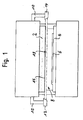
- the press brake shown in Fig. 1 has an upper tool or a press beam 2, the or to a working movement vertically after down against a lower tool 4 can be driven to a on to bend the workpiece 4 resting on the lower tool 4. While This working movement is an opening gap 8 between the upper tool 2 and the workpiece 6 is gradually closed.
- the support arms 10 carry a transmitting device 12 and a Spatial receiving device 14, the parts of an optoelectronic Sensors and the upper tool 2 are aligned.
- the transmitting device 12 has a e.g. formed as an LED or laser diode light source with a transmission optics (not shown in the figures), which transmits the transmitted light the light source to a light beam 16 expands. In most cases of the invention, it is useful to expand the light beam 16 in such a way, that e.g. also parts of the upper tool 2 from the light beam 16 be detected (see also Fig. 2a, b).
- the receiving device 14 has a rectangular, e.g. in CMOS, CID, CCD or the like formed matrix receiver, which is acted upon by the light beam 16 and is sized so that the light beam with its full Cross section hits the receiver.
- the light beam 16 passes through the opening gap 8 below the upper tool 2.
- the outline of a correspondingly activated part of the receiving device 14 defines within the light beam 16 a voluminous Protective field 18 between the upper tool 2 and the lower tool 4, as described below in connection with FIGS. 2a and 2b is explained.
- 2a and 2b respectively show the upper tool 2, the lower tool 4, the workpiece resting thereon 6 and the circular in cross-section Light beam 16 in a schematic side view.
- the receiving device 14 with its reception matrix is dimensioned such that that the light beam 16 shown in Figures 2a and 2b with its full cross section impinges on the receiving device 14, so that by means of the reception matrix it can be detected whether the light path between light emitter 12 and light receiver 14 at any location the light beam 16 is interrupted.
- This information provided by the individual receiving elements of the receiving matrix are delivered, reach according to the invention to an evaluation control unit, which this Information processed in different ways:
- Those receiving elements which correspond to the one shown in FIGS. 2a and 2b, rectangular, arranged below the upper tool 2 Protective field 20 are assigned, provide signals that always to a Turn off the press brake lead when the light beam 16 in a partial area corresponding to the protective field 20 is interrupted.
- the protective field 20 is arranged stationary within the light beam 16, so that it is guaranteed that he is always directly below the Upper tool 2 is located, on which the optoelectronic sensor 12, 14 is attached.
- a measuring window 22 of which in the Figures 2a and 2b are shown in each case two pieces by way of example.
- the Signals supplied by the measurement windows 22 have been explained with reference to FIG Shutdown function no meaning and become exclusive a measurement of the machined workpiece 6 used.
- the shape of the silhouette of the Workpiece 6 are determined. It is also possible, for example, the Course of the underside of the workpiece 6 (see arrows A according to FIG. 2a) or the course of the top of the workpiece 6 (see arrows B in FIG 2b) within the measurement window 22 to determine.
- a measurement of the workpiece 6 via the measuring window 22 as well as the shutdown via the protective field 20 both be carried out simultaneously and alternately.
Landscapes
- Engineering & Computer Science (AREA)
- Mechanical Engineering (AREA)
- General Engineering & Computer Science (AREA)
- Bending Of Plates, Rods, And Pipes (AREA)
- Length Measuring Devices By Optical Means (AREA)
- Machine Tool Sensing Apparatuses (AREA)
- Presses And Accessory Devices Thereof (AREA)
Abstract
Description
Bei bestimmten Anwendungsfällen, insbesondere wenn der optoelektronische Sensor fest mit einem unbeweglichen Werkzeugteil, beispielsweise dem Gesenk einer Biegemaschine verbunden ist, können die Messfenster in einer festen vorgegebenen Relativposition zum beweglichen Werkzeugteil positioniert sein oder werden, um so sicherzustellen, dass sich die Messfenster trotz der stationären Anordnung des optoelektronischen Sensors mit dem beweglichen Werkzeugteil mitbewegen. So kann auch in diesen Fällen eine Überwachung der Qualität des Bearbeitungsvorgangs während der gesamten Bearbeitungszeit sichergestellt werden.
- Fig. 1
- eine schematische Frontansicht einer Gesenkbiegepresse, und
- Fig. 2a,b
- jeweils eine schematische Seitenansicht von Teilen dieser Gesenkbiegepresse in unterschiedlichen Phasen eines normalen Bearbeitungsvorgangs.
- 2
- Oberwerkzeug
- 4
- Unterwerkzeug
- 6
- Werkstück
- 8
- Öffnungsspalt
- 10
- Haltearme
- 12
- Sendeeinrichtung
- 14
- Empfangseinrichtung
- 16
- Lichtstrahl
- 18
- Schutzfeld
- 20
- Schutzfeld
- 22
- Messfenster
Claims (16)
- Verfahren zur Sicherung einer Werkzeugmaschine mit einem ersten Werkzeugteil (2), das Arbeitsbewegungen in Richtung eines zweiten Werkzeugteils (4) ausführt, um hierdurch einen Bearbeitungsvorgang an einem Werkstück (6) durchzuführen, bei dem ein optoelektronischer Sensor (12, 14) ein volumenförmiges Schutzfeld (18, 20) zwischen den Werkzeugteilen (2, 4) überwacht, indem Licht mittels einer Sendeeinrichtung (12) entlang eines zwischen den Werkzeugteilen (2, 4) ausgebildeten Öffnungsspalts (8) ausgesandt und mittels einer Empfangseinrichtung (14) detektiert wird, welche eine Matrix von lichtempfindlichen Elementen umfasst, wobei ein Anhalten des ersten Werkzeugteils (2) erfolgt, wenn einzelne oder bestimmte Gruppen der lichtempfindlichen Elemente kein Licht empfangen,
dadurch gekennzeichnet , dass aus den von den lichtempfindlichen Elementen gelieferten Signalen Relativpositionen zwischen einzelnen Werkstück- oder Werkzeugbereichen oder auf einzelne Werkstück- oder Werkzeugbereiche bezogene Messwerte ermittelt werden. - Verfahren nach Anspruch 1,
dadurch gekennzeichnet , dass durch die Auswertung der von den lichtempfindlichen Elementen gelieferten Signale eine Bestimmung des Schattenrisses von Werkstücken (6) oder Werkzeugen erfolgt. - Verfahren nach einem der vorhergehenden Ansprüche,
dadurch gekennzeichnet , dass in Abhängigkeit von den ermittelten Relativpositionen oder Messwertenein Bearbeitungsvorgang an einem Werkstück (6) bzw. eine Ansteuerung der Werkzeugmaschine,eine Beaufschlagung einer Signaleinrichtung,eine Klassifizierung des bearbeiteten Werkstücks (6), odereine Klassifizierung eines Werkzeugs erfolgt. - Verfahren nach einem der vorhergehenden Ansprüche,
dadurch gekennzeichnet , dass die Relativpositionen vor, während und/oder nach dem Bearbeitungsvorgang ermittelt werden. - Verfahren nach einem der vorhergehenden Ansprüche,
dadurch gekennzeichnet , dass Gruppen benachbarter lichtempfindlicher Elemente als Messfenster (22) definiert und nur die von diesen Messfenstern (22) gelieferten Signale zur Ermittlung der Relativpositionen herangezogen werden. - Verfahren nach Anspruch 5,
dadurch gekennzeichnet , dass die Messfenster (22) während eines Bearbeitungsvorgangs innerhalb der Matrix verschoben oder in ihrer Größe und/oder Form verändert werden. - Verfahren nach Anspruch 6,
dadurch gekennzeichnet , dass die Veränderung in Abhängigkeit von den ermittelten Relativpositionen oder Messwerten, von Betriebszuständen der Werkzeugmaschine und/oder von Eingaben einer Bedienperson erfolgt. - Verfahren nach einem der vorhergehenden Ansprüche,
dadurch gekennzeichnet , dass mittels Bildverarbeitungsalgorithmen Bereiche des Werkstücks (6) mit geradem Konturverlauf bestimmt und die Messfenster (22) in diese Bereiche gelegt werden. - Verfahren nach einem der Ansprüche 5 bis 8,
dadurch gekennzeichnet , dass die Messfenster (22) in einer festen Relativposition zum ersten Werkzeugteil (2) positioniert sind oder positioniert werden. - Optoelektronischer Sensor als Schutzeinrichtung zur Sicherung einer Werkzeugmaschine mit einem ersten Werkzeugteil (2) zur Ausführung von Arbeitsbewegungen in Richtung eines zweiten Werkzeugteils (4), um einen Bearbeitungsvorgang an einem Werkstück (6) durchzuführen, wobei der Sensor (12, 14) zum Überwachen eines volumenförmigen Schutzfeldes (18, 20 zwischen den Werkzeugteilen (2, 4) eine Sendeeinrichtung (12) zur Aussendung von Licht entlang eines zwischen den Werkzeugteilen (2, 4) ausgebildeten Öffnungsspalts (8) und eine eine Matrix von lichtempfindlichen Elementen umfassende Empfangseinrichtung (14) zur Detektion des ausgesandten Lichts aufweist, wobei der Sensor (12, 14) ferner eine Auswerte- und Steuereinheit zum Anhalten des ersten Werkzeugteils (2) besitzt, wenn einzelne oder bestimmte Gruppen der lichtempfindlichen Elemente kein Licht empfangen,
dadurch gekennzeichnet , dass die Auswerte- und Steuereinheit zusätzlich zur Ermittlung von Relativpositionen zwischen einzelnen Werkstück- oder Werkzeugbereichen oder von auf einzelne Werkstück- oder Werkzeugbereiche bezogenen Messwerten in Abhängigkeit von den durch die lichtempfindlichen Elemente gelieferten Signalen ausgelegt ist. - Optoelektronischer Sensor nach Anspruch 10,
dadurch gekennzeichnet , dass er zur Durchführung des Verfahrens nach einem der Ansprüche 1 bis 9 ausgebildet ist. - Optoelektronischer Sensor nach einem der Ansprüche 10 oder 11,
dadurch gekennzeichnet , dass die Sendeeinrichtung (12) zur Aussendung eines parallelen Lichtbündels (16) ausgelegt ist. - Optoelektronischer Sensor nach einem der Ansprüche 10 bis 12,
dadurch gekennzeichnet , dass er in einer festen Relativposition zum ersten (2) oder zum zweiten (4) Werkzeugteil an der Werkzeugmaschine angebracht ist. - Optoelektronischer Sensor nach einem der Ansprüche 10 bis 13,
dadurch gekennzeichnet , dass die Auswerte- und Steuereinheit und die Empfangseinrichtung (14) miteinander gekoppelt und insbesondere in einem gemeinsamen Gehäuse untergebracht sind. - Optoelektronischer Sensor nach einem der Ansprüche 10 bis 14,
dadurch gekennzeichnet , dass die Auswerte- und Steuereinheit Datenausgänge zur Abgabe von Abschaltsignalen und von die ermittelten Relativpositionen oder Messwerte beschreibenden Daten aufweist. - Optoelektronischer Sensor nach einem der Ansprüche 10 bis 15,
dadurch gekennzeichnet , dass die Werkzeugmaschine als Gesenk- oder Abkantpresse, Biege-, Schneid- oder Stanzmaschine ausgebildet ist.
Applications Claiming Priority (2)
| Application Number | Priority Date | Filing Date | Title |
|---|---|---|---|
| DE200410020024 DE102004020024A1 (de) | 2004-04-23 | 2004-04-23 | Verfahren zur Sicherung einer Werkzeugmaschine und optoelektronischer Sensor zur Durchführung eines solchen Verfahrens |
| DE102004020024 | 2004-04-23 |
Publications (5)
| Publication Number | Publication Date |
|---|---|
| EP1589279A2 true EP1589279A2 (de) | 2005-10-26 |
| EP1589279A3 EP1589279A3 (de) | 2005-11-30 |
| EP1589279B1 EP1589279B1 (de) | 2007-01-10 |
| EP1589279B2 EP1589279B2 (de) | 2013-10-23 |
| EP1589279B9 EP1589279B9 (de) | 2014-02-26 |
Family
ID=34934182
Family Applications (1)
| Application Number | Title | Priority Date | Filing Date |
|---|---|---|---|
| EP20050005261 Expired - Lifetime EP1589279B9 (de) | 2004-04-23 | 2005-03-10 | Verfahren zur Sicherung einer Werkzeugmaschine und optoelektronischer Sensor zur Durchführung eines solchen Verfahrens |
Country Status (4)
| Country | Link |
|---|---|
| US (1) | US7448242B2 (de) |
| EP (1) | EP1589279B9 (de) |
| JP (1) | JP2005319517A (de) |
| DE (2) | DE102004020024A1 (de) |
Cited By (9)
| Publication number | Priority date | Publication date | Assignee | Title |
|---|---|---|---|---|
| EP1914019A1 (de) * | 2006-10-18 | 2008-04-23 | Warcom S.p.A. | Abkantpresse und zugehöriges Verfahren zum Biegen von Werkstücken |
| WO2008002555A3 (en) * | 2006-06-26 | 2008-06-05 | Qualex Mfg Lc | Method and apparatus for detecting unsafe conditions |
| EP2053538A1 (de) | 2007-10-25 | 2009-04-29 | Sick Ag | Absicherung eines Überwachungsbereichs und visuelle Unterstützung einer automatisierten Bearbeitung |
| DE102009050850A1 (de) | 2009-10-19 | 2011-04-21 | Daimler Ag | Verfahren und Vorrichtung zum Überwachen von Schutz- und Standardbereichen |
| US8101917B2 (en) | 2006-06-26 | 2012-01-24 | Qualex Manufacturing Llc | Method and apparatus for detecting unsafe conditions |
| US8314393B2 (en) | 2008-12-23 | 2012-11-20 | Qualex Manufacturing, Lc | Method and apparatus for detecting unsafe conditions |
| EP2633925A1 (de) * | 2012-03-02 | 2013-09-04 | Fiessler Elektronik GmbH & Co. KG | Schwenkbiegemaschine mit einer Überwachungseinrichtung und Verfahren zum Betreiben einer sochen Schwenkbiegemaschine |
| CN104019746A (zh) * | 2014-06-20 | 2014-09-03 | 中国石油大学(北京) | 对物模试样压裂后裂缝形态的测量装置及方法 |
| DE202018103290U1 (de) | 2018-06-12 | 2019-09-16 | Pilz Gmbh & Co. Kg | Sicherheitseinrichtung für eine Maschine, insbesondere für eine Biegepresse |
Families Citing this family (26)
| Publication number | Priority date | Publication date | Assignee | Title |
|---|---|---|---|---|
| US8692877B2 (en) * | 2005-06-20 | 2014-04-08 | Lazer Safe Pty Ltd | Imaging and safety system and method for an industrial machine |
| EP1896203B1 (de) * | 2005-06-20 | 2020-08-19 | Lazer Safe Pty Ltd | Abbildungs- und sicherheitssystem und -verfahren für eine industriemaschine |
| AT502038B1 (de) * | 2005-07-06 | 2007-01-15 | Trumpf Maschinen Austria Gmbh | Sicherheitseinrichtung für eine abkantpresse und ein lamellenwerkzeug |
| JP4798770B2 (ja) * | 2005-12-27 | 2011-10-19 | 株式会社アマダ | 曲げ加工装置 |
| JP4877734B2 (ja) * | 2006-01-10 | 2012-02-15 | 株式会社アマダ | 曲げ加工装置 |
| JP4993556B2 (ja) * | 2006-01-18 | 2012-08-08 | 株式会社アマダ | 曲げ加工装置 |
| JP5044994B2 (ja) * | 2006-05-30 | 2012-10-10 | 株式会社日立製作所 | 挟まれ防止安全装置を具備した加工機 |
| CN100582680C (zh) * | 2006-12-05 | 2010-01-20 | 鸿富锦精密工业(深圳)有限公司 | 检测仪 |
| DE102007006306A1 (de) | 2007-01-30 | 2008-07-31 | Pilz Gmbh & Co. Kg | Sicherheitseinrichtung für eine Maschine |
| DE202008003444U1 (de) | 2007-03-05 | 2008-07-10 | Pilz Gmbh & Co. Kg | Sicherheitseinrichtung zum Absichern einer Maschine |
| DE502008002818D1 (de) | 2008-07-25 | 2011-04-21 | Fiessler Elektronik Gmbh & Co Kg | Umformeinrichtung |
| DE202010004438U1 (de) | 2010-03-29 | 2011-08-11 | Pilz Gmbh & Co. Kg | Sicherheitseinrichtung für eine Maschine, bei der ein erstes Maschinenteil eine Arbeitsbewegung gegen ein zweites Maschinenteil ausführt |
| DE202010017960U1 (de) | 2010-09-20 | 2013-04-17 | Bystronic Laser Ag | Schutzsystem für Bediensicherheit an Maschinen, insbesondere Gesenkbiegepressen |
| CN102284885A (zh) * | 2011-07-28 | 2011-12-21 | 常州昌隆机床制造有限公司 | 数控龙门机床全封闭式防护结构 |
| CN103084512A (zh) * | 2013-01-25 | 2013-05-08 | 丁松炎 | 折弯机光电保护安全装置 |
| KR102138512B1 (ko) * | 2013-03-26 | 2020-07-28 | 엘지전자 주식회사 | 디스플레이 디바이스 및 그의 제어 방법 |
| CN103691840B (zh) * | 2014-01-10 | 2016-05-11 | 中山广都机电有限公司 | 一种折弯机的安全保护装置 |
| JP6243954B2 (ja) * | 2016-04-14 | 2017-12-06 | 株式会社アマダホールディングス | プレスブレーキの安全装置 |
| AT518993B1 (de) * | 2016-11-18 | 2018-03-15 | Trumpf Maschinen Austria Gmbh & Co Kg | Verfahren zum Betrieb einer Biegemaschine |
| CN106975691A (zh) * | 2017-05-31 | 2017-07-25 | 成都亨通兆业精密机械有限公司 | 用于电气柜型材的生产加工装置 |
| CN107081373A (zh) * | 2017-05-31 | 2017-08-22 | 成都亨通兆业精密机械有限公司 | 用于铝材钻孔工序的快速固定方法 |
| US10197219B1 (en) | 2017-08-04 | 2019-02-05 | Jason Boyer | Secondary light curtain for detecting crush zone intrusion in a secondary process and associated method for use |
| CN107900139A (zh) * | 2017-12-29 | 2018-04-13 | 北京简易科技有限公司 | 一种冲压机及带料弯曲检测方法 |
| CN110456423B (zh) * | 2018-05-07 | 2024-03-19 | 特鲁普机械奥地利有限公司及两合公司 | 用于弯曲单元的切削碎屑识别 |
| CN111570660B (zh) * | 2020-06-05 | 2021-09-17 | 山东穆柯传感器有限公司 | 一种智能硅光矩阵折弯机保护装置及保护方法 |
| CN115780568B (zh) * | 2023-02-13 | 2023-04-18 | 山东新合源热传输科技有限公司 | 一种用于五金件冲压的应急报警装置 |
Family Cites Families (29)
| Publication number | Priority date | Publication date | Assignee | Title |
|---|---|---|---|---|
| US4166369A (en) † | 1978-04-06 | 1979-09-04 | Kabushiki Kaisha Komatsu Seisakusho | Safety device for press brake |
| US4249074A (en) * | 1978-06-06 | 1981-02-03 | Xenex Corporation | Intrusion detector for press brake |
| US4430879A (en) † | 1981-06-12 | 1984-02-14 | Hurco Manufacturing Company, Inc. | Apparatus for controlling a press brake |
| US4660703A (en) * | 1983-11-07 | 1987-04-28 | Nevio Filcich | Method and apparatus for machine safety |
| EP0166351A3 (de) † | 1984-06-27 | 1986-09-17 | Arnold Stucki | Vorrichtung an einer Maschine für Umformarbeiten an blechförmigen Materialien |
| US4709432A (en) * | 1984-10-01 | 1987-12-01 | Barrick Fred A | Combination device for applying tire chains and mounting a jack |
| CH665364A5 (fr) * | 1985-10-30 | 1988-05-13 | Cybelec Sa | Dispositif pour le controle automatique de l'operation de pliage lors du pliage avec une presse-plieuse. |
| CH669131A5 (fr) † | 1986-10-14 | 1989-02-28 | Cybelec Sa | Dispositif de securite d'une machine-outil. |
| JP2818441B2 (ja) * | 1989-07-20 | 1998-10-30 | 株式会社アマダ | 折曲加工装置 |
| JPH0792193B2 (ja) * | 1989-10-26 | 1995-10-09 | 国際制御株式会社 | プレス機械の光線式安全装置 |
| AU667057B2 (en) * | 1991-10-18 | 1996-03-07 | Thomas John Appleyard | Brake press safety apparatus |
| DE4422497C2 (de) * | 1994-06-28 | 1996-06-05 | Leuze Electronic Gmbh & Co | Vorrichtung und Verfahren zum optoelektronischen Erfassen von Gegenständen |
| JP3093671B2 (ja) * | 1997-02-14 | 2000-10-03 | 国際制御株式会社 | 光線式安全装置 |
| DE19825829C2 (de) † | 1998-06-10 | 2000-07-27 | Leica Microsystems | Verfahren zur Bestimmung des Abstandes P einer Kante eines Strukturelementes auf einem Substrat |
| DE19828000C2 (de) * | 1998-06-24 | 2000-06-21 | Schmersal Eot Gmbh & Co Kg | Verfahren zur optoelektronischen Überwachung eines Schutzbereichs |
| DE19835033C1 (de) * | 1998-07-23 | 1999-11-04 | Bellheimer Metallwerk Gmbh | Lagerlift |
| US6660993B2 (en) * | 1999-04-16 | 2003-12-09 | Tirops Safety-Technology Inc. | Safety apparatus and protection method for machines |
| DE19938639B4 (de) † | 1999-08-14 | 2006-08-24 | Pilz Gmbh & Co. Kg | Vorrichtung zur Absicherung eines Gefahrenbereichs, insbesondere des Gefahrenbereichs einer automatisiert arbeitenden Maschine |
| DE10000287B4 (de) * | 2000-01-07 | 2004-02-12 | Leuze Lumiflex Gmbh + Co. Kg | Vorrichtung und Verfahren zur Überwachung eines Erfassungsbereichs an einem Arbeitsmittel |
| DE10027156A1 (de) * | 2000-05-31 | 2001-12-06 | Fiessler Elektronik Ohg | Schutzeinrichtung für Maschinen, wie Abkantpressen, Schneidmaschinen, Stanzmaschinen oder dergleichen |
| US6389860B1 (en) * | 2000-08-11 | 2002-05-21 | Lion Machinery, Inc. | Control system for a press brake |
| DE20102192U1 (de) * | 2001-02-08 | 2001-06-21 | Argast, Martin, 72584 Hülben | Winkelgeber |
| DE10114784A1 (de) * | 2001-03-26 | 2002-10-10 | Sick Ag | Vorrichtung zur Überwachung eines Schutzfeldes |
| DE10123562A1 (de) * | 2001-05-15 | 2002-11-21 | Fiessler Elektronik Ohg | Schutzeinrichtung für Maschinen, wie Abkantpressen, Schneidemaschinen, Stanzmaschinen oder dergleichen |
| DE10143505B4 (de) * | 2001-09-05 | 2010-07-08 | Sick Ag | Sicherungsverfahren und optoelektronischer Sensor |
| DE10152543A1 (de) * | 2001-10-24 | 2003-05-08 | Sick Ag | Verfahren und Vorrichtung zum Steuern einer sicherheitsrelevanten Funktion einer Maschine |
| EP1319886B1 (de) * | 2001-12-13 | 2005-12-28 | Fiessler Elektronik GmbH & Co. KG | Schutzeinrichtung für Maschinen, wie Biegepressen, Schneidemaschinen, Stanzmaschinen oder dergleichen |
| EP1552214B1 (de) * | 2002-06-11 | 2011-10-26 | Kevin Stephen Davies | Sicherheitssystem |
| DE20217426U1 (de) * | 2002-11-05 | 2003-01-16 | Pilz GmbH & Co., 73760 Ostfildern | Sicherheitseinrichtung für eine Maschine, insbesondere für eine Biegepresse |
-
2004
- 2004-04-23 DE DE200410020024 patent/DE102004020024A1/de not_active Withdrawn
-
2005
- 2005-03-10 DE DE200550000296 patent/DE502005000296D1/de not_active Expired - Lifetime
- 2005-03-10 EP EP20050005261 patent/EP1589279B9/de not_active Expired - Lifetime
- 2005-04-20 JP JP2005121861A patent/JP2005319517A/ja active Pending
- 2005-04-21 US US11/111,214 patent/US7448242B2/en not_active Expired - Fee Related
Non-Patent Citations (1)
| Title |
|---|
| None |
Cited By (13)
| Publication number | Priority date | Publication date | Assignee | Title |
|---|---|---|---|---|
| US8101917B2 (en) | 2006-06-26 | 2012-01-24 | Qualex Manufacturing Llc | Method and apparatus for detecting unsafe conditions |
| WO2008002555A3 (en) * | 2006-06-26 | 2008-06-05 | Qualex Mfg Lc | Method and apparatus for detecting unsafe conditions |
| US7439512B2 (en) | 2006-06-26 | 2008-10-21 | Qualex Manufacturing Llc | Method and apparatus for detecting unsafe conditions |
| CN101528382B (zh) * | 2006-06-26 | 2012-10-03 | 夸里科斯制造有限公司 | 用于检测不安全情况的方法和装置 |
| EP1914019A1 (de) * | 2006-10-18 | 2008-04-23 | Warcom S.p.A. | Abkantpresse und zugehöriges Verfahren zum Biegen von Werkstücken |
| EP2053538A1 (de) | 2007-10-25 | 2009-04-29 | Sick Ag | Absicherung eines Überwachungsbereichs und visuelle Unterstützung einer automatisierten Bearbeitung |
| US8314393B2 (en) | 2008-12-23 | 2012-11-20 | Qualex Manufacturing, Lc | Method and apparatus for detecting unsafe conditions |
| DE102009050850A1 (de) | 2009-10-19 | 2011-04-21 | Daimler Ag | Verfahren und Vorrichtung zum Überwachen von Schutz- und Standardbereichen |
| DE102009050850B4 (de) | 2009-10-19 | 2019-01-03 | Pilz Gmbh & Co. Kg | Verfahren und Vorrichtung zum Überwachen von Schutz- und Standardbereichen |
| EP2633925A1 (de) * | 2012-03-02 | 2013-09-04 | Fiessler Elektronik GmbH & Co. KG | Schwenkbiegemaschine mit einer Überwachungseinrichtung und Verfahren zum Betreiben einer sochen Schwenkbiegemaschine |
| CN104019746A (zh) * | 2014-06-20 | 2014-09-03 | 中国石油大学(北京) | 对物模试样压裂后裂缝形态的测量装置及方法 |
| CN104019746B (zh) * | 2014-06-20 | 2017-01-25 | 中国石油大学(北京) | 对物模试样压裂后裂缝形态的测量装置及方法 |
| DE202018103290U1 (de) | 2018-06-12 | 2019-09-16 | Pilz Gmbh & Co. Kg | Sicherheitseinrichtung für eine Maschine, insbesondere für eine Biegepresse |
Also Published As
| Publication number | Publication date |
|---|---|
| DE102004020024A1 (de) | 2005-11-10 |
| DE502005000296D1 (de) | 2007-02-22 |
| JP2005319517A (ja) | 2005-11-17 |
| EP1589279A3 (de) | 2005-11-30 |
| EP1589279B2 (de) | 2013-10-23 |
| EP1589279B9 (de) | 2014-02-26 |
| US7448242B2 (en) | 2008-11-11 |
| EP1589279B1 (de) | 2007-01-10 |
| US20050235790A1 (en) | 2005-10-27 |
Similar Documents
| Publication | Publication Date | Title |
|---|---|---|
| EP1589279B2 (de) | Verfahren zur Sicherung einer Werkzeugmaschine und optoelektronischer Sensor zur Durchführung eines solchen Verfahrens | |
| EP2076357B1 (de) | Werkzeugmaschinenüberwachungsvorrichtung | |
| EP3038786B1 (de) | Verfahren zum feststellen von abweichungen einer ist-lage eines laserbearbeitungskopfes von seiner soll-lage sowie laserbearbeitungsmaschine zur durchführung des verfahrens | |
| EP3321557B1 (de) | Deformationseinrichtung und verfahren zum betreiben einer deformationseinrichtung | |
| EP1970667B1 (de) | Maschnielle Anordung für die Blechfertigung mit einer Vorrichtung zur Überprüfung einer Werkstücköffnung als Ergebnis einer Werkstückbearbeitung | |
| AT518993B1 (de) | Verfahren zum Betrieb einer Biegemaschine | |
| DE10143505B4 (de) | Sicherungsverfahren und optoelektronischer Sensor | |
| DE10327388B4 (de) | Schutzeinrichtung | |
| EP1437542B1 (de) | Lichtgitter und Verfahren zu dessen Justierung | |
| DE2734804C2 (de) | Verfahren zum Einstellen einer Ausgangslinie innerhalb einer automatischen Steuerung für eine Werkzeugmaschine und Positioniervorrichtung für eine Werkzeugmaschine zum Durchführen des Verfahrens | |
| DE10309399A1 (de) | Sicherungsverfahren und optoelektronischer Sensor | |
| AT522419B1 (de) | Messvorrichtung zur Bestimmung des Biegewinkels | |
| EP3566793B1 (de) | Schneidbutzenerkennung für biegezellen | |
| AT520726B1 (de) | Verfahren zur Überwachung einer Fertigungsanlage sowie Fertigungsanlage mit einem Sicherheitssystem | |
| AT518894A4 (de) | Biegemaschine mit einer Biegeinformations-Anzeigevorrichtung | |
| EP2227348B1 (de) | Überwachungseinheit für einen überwachungsbereich in einer werkzeugmaschine | |
| EP1746335B1 (de) | Verfahren zur Sicherung einer Biegepresse und optoelektronischer Sensor zur Durchführung eines solchen Verfahrens | |
| DE202010017960U1 (de) | Schutzsystem für Bediensicherheit an Maschinen, insbesondere Gesenkbiegepressen | |
| EP2431650A1 (de) | Schutzsystem für Bediensicherheit an Maschinen, insbesondere Gesenkbiegepressen | |
| WO2020023988A1 (de) | Verfahren zum betreiben einer biegepresse | |
| EP1589355B1 (de) | Verfahren zur Justage einer Sicherheitseinrichtung und optoelektronische Sicherheitseinrichtung | |
| DE3940246C2 (de) | ||
| DE2817787C2 (de) | ||
| EP0950938B1 (de) | Verfahren und Vorrichtung zur Qualitätsüberwachung | |
| EP0607498A1 (de) | Verfahren zum Betrieb einer Schneidpresse und Schneidpresse |
Legal Events
| Date | Code | Title | Description |
|---|---|---|---|
| PUAI | Public reference made under article 153(3) epc to a published international application that has entered the european phase |
Free format text: ORIGINAL CODE: 0009012 |
|
| PUAL | Search report despatched |
Free format text: ORIGINAL CODE: 0009013 |
|
| AK | Designated contracting states |
Kind code of ref document: A2 Designated state(s): AT BE BG CH CY CZ DE DK EE ES FI FR GB GR HU IE IS IT LI LT LU MC NL PL PT RO SE SI SK TR |
|
| AX | Request for extension of the european patent |
Extension state: AL BA HR LV MK YU |
|
| AK | Designated contracting states |
Kind code of ref document: A3 Designated state(s): AT BE BG CH CY CZ DE DK EE ES FI FR GB GR HU IE IS IT LI LT LU MC NL PL PT RO SE SI SK TR |
|
| AX | Request for extension of the european patent |
Extension state: AL BA HR LV MK YU |
|
| RIC1 | Information provided on ipc code assigned before grant |
Ipc: 7B 21D 55/00 B Ipc: 7F 16P 3/04 B Ipc: 7B 30B 15/28 B Ipc: 7F 16P 3/14 A |
|
| 17P | Request for examination filed |
Effective date: 20060420 |
|
| GRAP | Despatch of communication of intention to grant a patent |
Free format text: ORIGINAL CODE: EPIDOSNIGR1 |
|
| AKX | Designation fees paid |
Designated state(s): AT BE BG CH CY CZ DE DK EE ES FI FR GB GR HU IE IS IT LI LT LU MC NL PL PT RO SE SI SK TR |
|
| GRAS | Grant fee paid |
Free format text: ORIGINAL CODE: EPIDOSNIGR3 |
|
| GRAA | (expected) grant |
Free format text: ORIGINAL CODE: 0009210 |
|
| AK | Designated contracting states |
Kind code of ref document: B1 Designated state(s): AT BE BG CH CY CZ DE DK EE ES FI FR GB GR HU IE IS IT LI LT LU MC NL PL PT RO SE SI SK TR |
|
| PG25 | Lapsed in a contracting state [announced via postgrant information from national office to epo] |
Ref country code: DK Free format text: LAPSE BECAUSE OF FAILURE TO SUBMIT A TRANSLATION OF THE DESCRIPTION OR TO PAY THE FEE WITHIN THE PRESCRIBED TIME-LIMIT Effective date: 20070110 Ref country code: SI Free format text: LAPSE BECAUSE OF FAILURE TO SUBMIT A TRANSLATION OF THE DESCRIPTION OR TO PAY THE FEE WITHIN THE PRESCRIBED TIME-LIMIT Effective date: 20070110 Ref country code: NL Free format text: LAPSE BECAUSE OF FAILURE TO SUBMIT A TRANSLATION OF THE DESCRIPTION OR TO PAY THE FEE WITHIN THE PRESCRIBED TIME-LIMIT Effective date: 20070110 Ref country code: IE Free format text: LAPSE BECAUSE OF FAILURE TO SUBMIT A TRANSLATION OF THE DESCRIPTION OR TO PAY THE FEE WITHIN THE PRESCRIBED TIME-LIMIT Effective date: 20070110 Ref country code: PL Free format text: LAPSE BECAUSE OF FAILURE TO SUBMIT A TRANSLATION OF THE DESCRIPTION OR TO PAY THE FEE WITHIN THE PRESCRIBED TIME-LIMIT Effective date: 20070110 Ref country code: FI Free format text: LAPSE BECAUSE OF FAILURE TO SUBMIT A TRANSLATION OF THE DESCRIPTION OR TO PAY THE FEE WITHIN THE PRESCRIBED TIME-LIMIT Effective date: 20070110 |
|
| REG | Reference to a national code |
Ref country code: GB Ref legal event code: FG4D Free format text: NOT ENGLISH |
|
| RAP2 | Party data changed (patent owner data changed or rights of a patent transferred) |
Owner name: SICK AG |
|
| REG | Reference to a national code |
Ref country code: IE Ref legal event code: FG4D Free format text: LANGUAGE OF EP DOCUMENT: GERMAN |
|
| REF | Corresponds to: |
Ref document number: 502005000296 Country of ref document: DE Date of ref document: 20070222 Kind code of ref document: P |
|
| GBT | Gb: translation of ep patent filed (gb section 77(6)(a)/1977) |
Effective date: 20070222 |
|
| NLT2 | Nl: modifications (of names), taken from the european patent patent bulletin |
Owner name: SICK AG Effective date: 20070214 |
|
| PG25 | Lapsed in a contracting state [announced via postgrant information from national office to epo] |
Ref country code: BG Free format text: LAPSE BECAUSE OF FAILURE TO SUBMIT A TRANSLATION OF THE DESCRIPTION OR TO PAY THE FEE WITHIN THE PRESCRIBED TIME-LIMIT Effective date: 20070410 Ref country code: SE Free format text: LAPSE BECAUSE OF FAILURE TO SUBMIT A TRANSLATION OF THE DESCRIPTION OR TO PAY THE FEE WITHIN THE PRESCRIBED TIME-LIMIT Effective date: 20070410 |
|
| PG25 | Lapsed in a contracting state [announced via postgrant information from national office to epo] |
Ref country code: ES Free format text: LAPSE BECAUSE OF FAILURE TO SUBMIT A TRANSLATION OF THE DESCRIPTION OR TO PAY THE FEE WITHIN THE PRESCRIBED TIME-LIMIT Effective date: 20070421 |
|
| PG25 | Lapsed in a contracting state [announced via postgrant information from national office to epo] |
Ref country code: IS Free format text: LAPSE BECAUSE OF FAILURE TO SUBMIT A TRANSLATION OF THE DESCRIPTION OR TO PAY THE FEE WITHIN THE PRESCRIBED TIME-LIMIT Effective date: 20070510 |
|
| PG25 | Lapsed in a contracting state [announced via postgrant information from national office to epo] |
Ref country code: PT Free format text: LAPSE BECAUSE OF FAILURE TO SUBMIT A TRANSLATION OF THE DESCRIPTION OR TO PAY THE FEE WITHIN THE PRESCRIBED TIME-LIMIT Effective date: 20070611 |
|
| NLV1 | Nl: lapsed or annulled due to failure to fulfill the requirements of art. 29p and 29m of the patents act | ||
| ET | Fr: translation filed | ||
| REG | Reference to a national code |
Ref country code: IE Ref legal event code: FD4D |
|
| PLBI | Opposition filed |
Free format text: ORIGINAL CODE: 0009260 |
|
| PLAX | Notice of opposition and request to file observation + time limit sent |
Free format text: ORIGINAL CODE: EPIDOSNOBS2 |
|
| 26 | Opposition filed |
Opponent name: PILZ GMBH & CO. KG Effective date: 20071009 |
|
| PG25 | Lapsed in a contracting state [announced via postgrant information from national office to epo] |
Ref country code: SK Free format text: LAPSE BECAUSE OF FAILURE TO SUBMIT A TRANSLATION OF THE DESCRIPTION OR TO PAY THE FEE WITHIN THE PRESCRIBED TIME-LIMIT Effective date: 20070110 |
|
| BERE | Be: lapsed |
Owner name: SICK A.G. Effective date: 20070331 |
|
| PG25 | Lapsed in a contracting state [announced via postgrant information from national office to epo] |
Ref country code: RO Free format text: LAPSE BECAUSE OF FAILURE TO SUBMIT A TRANSLATION OF THE DESCRIPTION OR TO PAY THE FEE WITHIN THE PRESCRIBED TIME-LIMIT Effective date: 20070110 Ref country code: BE Free format text: LAPSE BECAUSE OF NON-PAYMENT OF DUE FEES Effective date: 20070331 Ref country code: CZ Free format text: LAPSE BECAUSE OF FAILURE TO SUBMIT A TRANSLATION OF THE DESCRIPTION OR TO PAY THE FEE WITHIN THE PRESCRIBED TIME-LIMIT Effective date: 20070110 |
|
| PG25 | Lapsed in a contracting state [announced via postgrant information from national office to epo] |
Ref country code: MC Free format text: LAPSE BECAUSE OF NON-PAYMENT OF DUE FEES Effective date: 20070331 |
|
| PG25 | Lapsed in a contracting state [announced via postgrant information from national office to epo] |
Ref country code: LT Free format text: LAPSE BECAUSE OF FAILURE TO SUBMIT A TRANSLATION OF THE DESCRIPTION OR TO PAY THE FEE WITHIN THE PRESCRIBED TIME-LIMIT Effective date: 20070110 |
|
| PLBB | Reply of patent proprietor to notice(s) of opposition received |
Free format text: ORIGINAL CODE: EPIDOSNOBS3 |
|
| PG25 | Lapsed in a contracting state [announced via postgrant information from national office to epo] |
Ref country code: GR Free format text: LAPSE BECAUSE OF FAILURE TO SUBMIT A TRANSLATION OF THE DESCRIPTION OR TO PAY THE FEE WITHIN THE PRESCRIBED TIME-LIMIT Effective date: 20070411 |
|
| PG25 | Lapsed in a contracting state [announced via postgrant information from national office to epo] |
Ref country code: AT Free format text: LAPSE BECAUSE OF NON-PAYMENT OF DUE FEES Effective date: 20070310 |
|
| PLAB | Opposition data, opponent's data or that of the opponent's representative modified |
Free format text: ORIGINAL CODE: 0009299OPPO |
|
| PG25 | Lapsed in a contracting state [announced via postgrant information from national office to epo] |
Ref country code: EE Free format text: LAPSE BECAUSE OF FAILURE TO SUBMIT A TRANSLATION OF THE DESCRIPTION OR TO PAY THE FEE WITHIN THE PRESCRIBED TIME-LIMIT Effective date: 20070110 |
|
| APBM | Appeal reference recorded |
Free format text: ORIGINAL CODE: EPIDOSNREFNO |
|
| APBP | Date of receipt of notice of appeal recorded |
Free format text: ORIGINAL CODE: EPIDOSNNOA2O |
|
| APAH | Appeal reference modified |
Free format text: ORIGINAL CODE: EPIDOSCREFNO |
|
| APAW | Appeal reference deleted |
Free format text: ORIGINAL CODE: EPIDOSDREFNO |
|
| APBM | Appeal reference recorded |
Free format text: ORIGINAL CODE: EPIDOSNREFNO |
|
| APBP | Date of receipt of notice of appeal recorded |
Free format text: ORIGINAL CODE: EPIDOSNNOA2O |
|
| PG25 | Lapsed in a contracting state [announced via postgrant information from national office to epo] |
Ref country code: CY Free format text: LAPSE BECAUSE OF FAILURE TO SUBMIT A TRANSLATION OF THE DESCRIPTION OR TO PAY THE FEE WITHIN THE PRESCRIBED TIME-LIMIT Effective date: 20070110 |
|
| APBQ | Date of receipt of statement of grounds of appeal recorded |
Free format text: ORIGINAL CODE: EPIDOSNNOA3O |
|
| PG25 | Lapsed in a contracting state [announced via postgrant information from national office to epo] |
Ref country code: LU Free format text: LAPSE BECAUSE OF NON-PAYMENT OF DUE FEES Effective date: 20070310 |
|
| PG25 | Lapsed in a contracting state [announced via postgrant information from national office to epo] |
Ref country code: HU Free format text: LAPSE BECAUSE OF FAILURE TO SUBMIT A TRANSLATION OF THE DESCRIPTION OR TO PAY THE FEE WITHIN THE PRESCRIBED TIME-LIMIT Effective date: 20070711 |
|
| PGFP | Annual fee paid to national office [announced via postgrant information from national office to epo] |
Ref country code: TR Payment date: 20120305 Year of fee payment: 8 |
|
| PGFP | Annual fee paid to national office [announced via postgrant information from national office to epo] |
Ref country code: IT Payment date: 20120324 Year of fee payment: 8 |
|
| APBU | Appeal procedure closed |
Free format text: ORIGINAL CODE: EPIDOSNNOA9O |
|
| PGFP | Annual fee paid to national office [announced via postgrant information from national office to epo] |
Ref country code: CH Payment date: 20130319 Year of fee payment: 9 Ref country code: GB Payment date: 20130318 Year of fee payment: 9 Ref country code: FR Payment date: 20130329 Year of fee payment: 9 |
|
| PUAH | Patent maintained in amended form |
Free format text: ORIGINAL CODE: 0009272 |
|
| STAA | Information on the status of an ep patent application or granted ep patent |
Free format text: STATUS: PATENT MAINTAINED AS AMENDED |
|
| 27A | Patent maintained in amended form |
Effective date: 20131023 |
|
| AK | Designated contracting states |
Kind code of ref document: B2 Designated state(s): AT BE BG CH CY CZ DE DK EE ES FI FR GB GR HU IE IS IT LI LT LU MC NL PL PT RO SE SI SK TR |
|
| REG | Reference to a national code |
Ref country code: CH Ref legal event code: AELC |
|
| REG | Reference to a national code |
Ref country code: DE Ref legal event code: R102 Ref document number: 502005000296 Country of ref document: DE Effective date: 20131023 |
|
| REG | Reference to a national code |
Ref country code: CH Ref legal event code: PL |
|
| GBPC | Gb: european patent ceased through non-payment of renewal fee |
Effective date: 20140310 |
|
| REG | Reference to a national code |
Ref country code: FR Ref legal event code: ST Effective date: 20141128 |
|
| PG25 | Lapsed in a contracting state [announced via postgrant information from national office to epo] |
Ref country code: CH Free format text: LAPSE BECAUSE OF NON-PAYMENT OF DUE FEES Effective date: 20140331 Ref country code: LI Free format text: LAPSE BECAUSE OF NON-PAYMENT OF DUE FEES Effective date: 20140331 Ref country code: GB Free format text: LAPSE BECAUSE OF NON-PAYMENT OF DUE FEES Effective date: 20140310 Ref country code: FR Free format text: LAPSE BECAUSE OF NON-PAYMENT OF DUE FEES Effective date: 20140331 |
|
| PG25 | Lapsed in a contracting state [announced via postgrant information from national office to epo] |
Ref country code: IT Free format text: LAPSE BECAUSE OF NON-PAYMENT OF DUE FEES Effective date: 20140310 |
|
| PGFP | Annual fee paid to national office [announced via postgrant information from national office to epo] |
Ref country code: DE Payment date: 20150324 Year of fee payment: 11 |
|
| REG | Reference to a national code |
Ref country code: DE Ref legal event code: R119 Ref document number: 502005000296 Country of ref document: DE |
|
| PG25 | Lapsed in a contracting state [announced via postgrant information from national office to epo] |
Ref country code: DE Free format text: LAPSE BECAUSE OF NON-PAYMENT OF DUE FEES Effective date: 20161001 |
|
| PG25 | Lapsed in a contracting state [announced via postgrant information from national office to epo] |
Ref country code: TR Free format text: LAPSE BECAUSE OF NON-PAYMENT OF DUE FEES Effective date: 20140310 |